EP2987213B1 - Subsea power distribution device and system - Google Patents
Subsea power distribution device and system Download PDFInfo
- Publication number
- EP2987213B1 EP2987213B1 EP14717776.0A EP14717776A EP2987213B1 EP 2987213 B1 EP2987213 B1 EP 2987213B1 EP 14717776 A EP14717776 A EP 14717776A EP 2987213 B1 EP2987213 B1 EP 2987213B1
- Authority
- EP
- European Patent Office
- Prior art keywords
- subsea
- power distribution
- distribution device
- switch
- power
- Prior art date
- Legal status (The legal status is an assumption and is not a legal conclusion. Google has not performed a legal analysis and makes no representation as to the accuracy of the status listed.)
- Active
Links
Images

Classifications
-
- H—ELECTRICITY
- H02—GENERATION; CONVERSION OR DISTRIBUTION OF ELECTRIC POWER
- H02B—BOARDS, SUBSTATIONS OR SWITCHING ARRANGEMENTS FOR THE SUPPLY OR DISTRIBUTION OF ELECTRIC POWER
- H02B7/00—Enclosed substations, e.g. compact substations
-
- E—FIXED CONSTRUCTIONS
- E21—EARTH OR ROCK DRILLING; MINING
- E21B—EARTH OR ROCK DRILLING; OBTAINING OIL, GAS, WATER, SOLUBLE OR MELTABLE MATERIALS OR A SLURRY OF MINERALS FROM WELLS
- E21B33/00—Sealing or packing boreholes or wells
- E21B33/02—Surface sealing or packing
- E21B33/03—Well heads; Setting-up thereof
- E21B33/035—Well heads; Setting-up thereof specially adapted for underwater installations
-
- H—ELECTRICITY
- H01—ELECTRIC ELEMENTS
- H01F—MAGNETS; INDUCTANCES; TRANSFORMERS; SELECTION OF MATERIALS FOR THEIR MAGNETIC PROPERTIES
- H01F27/00—Details of transformers or inductances, in general
- H01F27/02—Casings
-
- H—ELECTRICITY
- H01—ELECTRIC ELEMENTS
- H01F—MAGNETS; INDUCTANCES; TRANSFORMERS; SELECTION OF MATERIALS FOR THEIR MAGNETIC PROPERTIES
- H01F27/00—Details of transformers or inductances, in general
- H01F27/08—Cooling; Ventilating
- H01F27/10—Liquid cooling
- H01F27/12—Oil cooling
-
- H—ELECTRICITY
- H02—GENERATION; CONVERSION OR DISTRIBUTION OF ELECTRIC POWER
- H02G—INSTALLATION OF ELECTRIC CABLES OR LINES, OR OF COMBINED OPTICAL AND ELECTRIC CABLES OR LINES
- H02G9/00—Installations of electric cables or lines in or on the ground or water
- H02G9/02—Installations of electric cables or lines in or on the ground or water laid directly in or on the ground, river-bed or sea-bottom; Coverings therefor, e.g. tile
-
- H—ELECTRICITY
- H02—GENERATION; CONVERSION OR DISTRIBUTION OF ELECTRIC POWER
- H02H—EMERGENCY PROTECTIVE CIRCUIT ARRANGEMENTS
- H02H7/00—Emergency protective circuit arrangements specially adapted for specific types of electric machines or apparatus or for sectionalised protection of cable or line systems, and effecting automatic switching in the event of an undesired change from normal working conditions
- H02H7/04—Emergency protective circuit arrangements specially adapted for specific types of electric machines or apparatus or for sectionalised protection of cable or line systems, and effecting automatic switching in the event of an undesired change from normal working conditions for transformers
-
- H—ELECTRICITY
- H02—GENERATION; CONVERSION OR DISTRIBUTION OF ELECTRIC POWER
- H02J—ELECTRIC POWER NETWORKS; CIRCUIT ARRANGEMENTS OR SYSTEMS FOR SUPPLYING OR DISTRIBUTING ELECTRIC POWER; SYSTEMS FOR STORING ELECTRIC ENERGY
- H02J13/00—Circuit arrangements for providing remote monitoring or remote control of equipment in a power distribution network
-
- H—ELECTRICITY
- H02—GENERATION; CONVERSION OR DISTRIBUTION OF ELECTRIC POWER
- H02J—ELECTRIC POWER NETWORKS; CIRCUIT ARRANGEMENTS OR SYSTEMS FOR SUPPLYING OR DISTRIBUTING ELECTRIC POWER; SYSTEMS FOR STORING ELECTRIC ENERGY
- H02J3/00—Circuit arrangements for AC mains or AC distribution networks
-
- H—ELECTRICITY
- H01—ELECTRIC ELEMENTS
- H01F—MAGNETS; INDUCTANCES; TRANSFORMERS; SELECTION OF MATERIALS FOR THEIR MAGNETIC PROPERTIES
- H01F27/00—Details of transformers or inductances, in general
- H01F27/28—Coils; Windings; Conductive connections
-
- H—ELECTRICITY
- H02—GENERATION; CONVERSION OR DISTRIBUTION OF ELECTRIC POWER
- H02H—EMERGENCY PROTECTIVE CIRCUIT ARRANGEMENTS
- H02H7/00—Emergency protective circuit arrangements specially adapted for specific types of electric machines or apparatus or for sectionalised protection of cable or line systems, and effecting automatic switching in the event of an undesired change from normal working conditions
- H02H7/26—Sectionalised protection of cable or line systems, e.g. for disconnecting a section on which a short-circuit, earth fault, or arc discharge has occured
-
- Y—GENERAL TAGGING OF NEW TECHNOLOGICAL DEVELOPMENTS; GENERAL TAGGING OF CROSS-SECTIONAL TECHNOLOGIES SPANNING OVER SEVERAL SECTIONS OF THE IPC; TECHNICAL SUBJECTS COVERED BY FORMER USPC CROSS-REFERENCE ART COLLECTIONS [XRACs] AND DIGESTS
- Y02—TECHNOLOGIES OR APPLICATIONS FOR MITIGATION OR ADAPTATION AGAINST CLIMATE CHANGE
- Y02E—REDUCTION OF GREENHOUSE GAS [GHG] EMISSIONS, RELATED TO ENERGY GENERATION, TRANSMISSION OR DISTRIBUTION
- Y02E60/00—Enabling technologies; Technologies with a potential or indirect contribution to GHG emissions mitigation
-
- Y—GENERAL TAGGING OF NEW TECHNOLOGICAL DEVELOPMENTS; GENERAL TAGGING OF CROSS-SECTIONAL TECHNOLOGIES SPANNING OVER SEVERAL SECTIONS OF THE IPC; TECHNICAL SUBJECTS COVERED BY FORMER USPC CROSS-REFERENCE ART COLLECTIONS [XRACs] AND DIGESTS
- Y04—INFORMATION OR COMMUNICATION TECHNOLOGIES HAVING AN IMPACT ON OTHER TECHNOLOGY AREAS
- Y04S—SYSTEMS INTEGRATING TECHNOLOGIES RELATED TO POWER NETWORK OPERATION, COMMUNICATION OR INFORMATION TECHNOLOGIES FOR IMPROVING THE ELECTRICAL POWER GENERATION, TRANSMISSION, DISTRIBUTION, MANAGEMENT OR USAGE, i.e. SMART GRIDS
- Y04S10/00—Systems supporting electrical power generation, transmission or distribution
- Y04S10/16—Electric power substations
-
- Y—GENERAL TAGGING OF NEW TECHNOLOGICAL DEVELOPMENTS; GENERAL TAGGING OF CROSS-SECTIONAL TECHNOLOGIES SPANNING OVER SEVERAL SECTIONS OF THE IPC; TECHNICAL SUBJECTS COVERED BY FORMER USPC CROSS-REFERENCE ART COLLECTIONS [XRACs] AND DIGESTS
- Y04—INFORMATION OR COMMUNICATION TECHNOLOGIES HAVING AN IMPACT ON OTHER TECHNOLOGY AREAS
- Y04S—SYSTEMS INTEGRATING TECHNOLOGIES RELATED TO POWER NETWORK OPERATION, COMMUNICATION OR INFORMATION TECHNOLOGIES FOR IMPROVING THE ELECTRICAL POWER GENERATION, TRANSMISSION, DISTRIBUTION, MANAGEMENT OR USAGE, i.e. SMART GRIDS
- Y04S10/00—Systems supporting electrical power generation, transmission or distribution
- Y04S10/20—Systems supporting electrical power generation, transmission or distribution using protection elements, arrangements or systems
Definitions
- the present invention relates to distribution of electric power to subsea equipment.
- the invention relates to a subsea power distribution device, comprising a watertight housing accommodating a transformer, the transformer having a primary winding and a plurality of secondary windings; input terminals, electrically connected to the primary winding, arranged to be connected to a remote power supply; and output terminals, electrically connected to the secondary windings, arranged to be connected to subsea power consuming devices.
- the invention also relates to a corresponding subsea power distribution system and method.
- subsea equipment such as subsea production installations.
- subsea equipment may include, i.a., compressors, pumps, and any other electrically powered subsea equipment.
- the electrical power to be distributed to such subsea equipment may be supplied from land, e.g. an onshore power plant, or from an offshore power generating facility, e.g. on a ship or platform.
- Such subsea equipment may have high power requirements, and electric power must usually be transferred across long distances.
- a high voltage is used for the remote power supply.
- the high voltage power supply is connected to a subsea power distribution device which includes a transformer that provides a lower voltage power supply which is connected to subsea power consuming devices.
- the transformer may be accommodated in a watertight housing.
- the transformer may be a multi-winding transformer, having a primary winding and a plurality of secondary windings.
- the primary winding is electrically connected to input terminals which arranged to be connected to the remote, high voltage power supply.
- the secondary windings are electrically connected to output terminals which are further arranged to be connected to the subsea power consuming devices.
- a disadvantage of such an arrangement is that the secondary transformer windings have no protection against a failure in one of the circuits connected to a secondary winding, e.g. a ground fault, an overload or a short circuit in one of the subsea power consuming devices.
- a hydrocarbon production system comprising a topside installation connected to an underwater distribution unit.
- the underwater distribution unit comprises an underwater transformer and protection means having associated switching devices contained each in separate housings. The switches being positioned far from the transformer, the risk of fault in the circuit between the transformer and the switches is increased.
- Other examples of submarine systems for distribution of electric power can be found in documents WO02/41336A1 , US2009/226262A1 , US2003/025584A1 and WO2007/055594A1 .
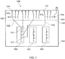
- Figure 1 is a schematic block diagram illustrating aspects of a subsea power distribution device.
- the subsea power distribution device comprises a watertight housing 101 which accommodates at least one transformer 102. Also shown are additional transformers 103, 104, which may also be included in the watertight housing 101. As will be appreciated, any suitable number of transformers, for instance 1, 2, 3 or 4 transformers, may be included in the power distribution device. Each additional transformer 103, 104 may e.g. be equal to, similar to, or different from the transformer 102.
- the transformer 102 has a primary winding and a plurality of secondary windings, i.e., a multiwinding transformer.
- the primary winding has not been shown, for simplicity of illustration.
- the plurality of secondary windings which in this example includes 4 secondary windings, has been illustrated within the transformer 102.
- Each secondary winding is feeding one power consuming device.
- the term power consuming device should be understood to mean either one single power consuming unit or a power distribution circuit segment which may include a plurality of power consuming units.
- the subsea power distribution device 100 includes input terminals that are electrically connected to the primary winding. These input terminals are also arranged to be connected to a remote power supply.
- the remote power supply may have high supply voltage of typically 50-150 kV, for instance 90kV.
- the high voltage power may be transferred over a long distance, such as from land, e.g. an onshore power plant, or from an offshore power generating facility, e.g. on a ship or platform, to the subsea site.
- the power distribution device 100 further includes output terminals which are electrically connected to the secondary windings and arranged to be connected to subsea power consuming devices.
- the secondary windings may typically supply a operating voltage in the range of 10 to 40 kV, or more particularly, in the range of 20 to 36 kV, e.g., 24kV.
- switches are arranged to break the connections between each secondary winding and a corresponding output terminal.
- the switches including the illustrated switches 113 and 123, are arranged within the watertight housing.
- the arrangement of the switches arranged to break the connections between each secondary winding and a corresponding output terminal avoids complete production stop in the event of an electrical fault in a secondary circuit, e.g., a overload, short-circuit or earth fault in a subsea power consuming device.
- a secondary circuit e.g., a overload, short-circuit or earth fault in a subsea power consuming device.
- Each switch makes it possible to isolate each separate secondary circuit in order to disconnect only the circuit which has a fault. When a secondary circuit is to be connected or disconnected, such isolating switches will give the opportunity of performing such a circuit isolation operation without the disconnecting the complete subsea transformer.
- the switches used in the power distribution device may e.g. be designed for operating in a voltage range of 10 to 40 kV, or more particularly, in the range of 20 to 36 kV, e.g., 24 kV.
- dielectric insulating fluid (oil) is used to fill the switch gap, which implies that a switch rated for a particular voltage when operated in air, may operate at a substantially higher (such as approx. three times higher) voltage when insulating fluid (oil) is used.
- one secondary winding 111 in the transformer 102 is connected through a conductor 112 to a switch 113.
- a further connector is connected between the switch 113 and the output terminal 114, which is arranged to be connected to a subsea power consuming device.
- another secondary winding 121 in the transformer 102 is connected through a conductor 122 to a switch 123.
- a further connector is connected between the switch 123 and the output terminal 124, which is also arranged to be connected to a subsea power consuming device.
- each switch e.g. the switch 123
- the switch 123 is placed as close as possible to the secondary winding of the transformer, so as to minimize the risk of a fault between the secondary winding and the switch, since such a fault cannot be isolated by means of the switch.
- each secondary winding of the transformer is provided with a corresponding switch, connected to the secondary winding through a conductor.
- Each switch includes a switch actuator, which actuates the switching function of the switch.
- the switch 113 is actuated by the switch actuator 115.
- two other, correspondingly operated switches are actuated by the same switch actuator 115.
- the switch 123 is actuated by another switch actuator 125.
- the switch actuator 125 Preferably, as shown, two other, correspondingly operated switches are actuated by the same switch actuator 125.
- the watertight housing 101 is configured with a first compartment 131 and a second compartment 141.
- the second compartment 141 is separate from the first compartment 131.
- the transformer is arranged within the first compartment 131 while the switches are arranged in the second compartment 141.
- the first compartment 131 and the second compartment 141 are advantageously oil-filled.
- the oil used is a dielectric isolating oil of a type known as transformer fluid.
- An example is known as MIDEL 7131.
- the first 131 and second 141 compartments may be configured as separate parts or as portions of a divided enclosure.
- the compartments, including the divided enclosure, should be designed and arranged to withstand subsea environment conditions, i.e. water pressure, salt, temperature variations, etc.
- the compartments may be made of a strong steel casing with cooling fins for heat exchange.
- the enclosure may advantageously include a top cover and suitable bushing boxes. Appropriate seals, closures, penetrators and connectors to sea-water for subsea environment may be chosen as appropriate by the skilled person.
- the switch actuator is (or the switch actuators are) contained within the watertight housing. Hence, as shown, the switch actuators 115 and 125 are contained within the watertight housing 101.
- the switch actuator is advantageously contained within the second compartment 141.
- electric penetrators are needed between the first and second compartments.
- the switch actuator is arranged external to the watertight housing.
- This problem has been solved by arranging a magnetic coupling between the actuator's electric motor, arranged outside the watertight housing, and a movable mechanism of the switch.
- the switch actuator may be connected to and arranged to be controlled by a control unit which is arranged separately from the watertight housing.
- the switch actuator may advantageously be an electrical switch actuator, e.g. including a motor, mechanical drive gear, a power supply such as a battery, and a control unit.
- the electric switch actuator may be configured to be fail safe.
- the battery may include an internal battery, an external battery, or a combination.
- the switch actuator may be a hydraulic or electro-hydraulic switch actuator.
- Figures 2 and 3 are schematic block diagrams illustrating certain further aspects of a subsea power distribution device.
- the subsea power distribution device 200 comprises a watertight housing in the same way as the device 100 described above with reference to figure 1 , although this housing has not been illustrated in figures 2 and 3 .
- the watertight housing accommodates a transformer which has a primary winding, schematically illustrated at 210 and a plurality of secondary windings; namely; the four secondary windings 211, 221, 231 and 241.
- Input terminals (schematically illustrated as one line) are electrically connected to the primary winding 210 and arranged to be connected to a remote power supply.
- a switch 250 has been shown to be interconnected in the supply line between the remote power supply and the primary winding 250.
- the subsea power distribution device 200 further comprises output terminals, which are electrically connected to the secondary windings and arranged to be connected to subsea power consuming devices, illustrated at 216, 226, 236 and 246.
- Switches illustrated in figure 2 at 211, 221, 231 and 241 respectively, are arranged to break the connections between each secondary winding and a corresponding output terminal which leads to a corresponding subsea power consuming device.
- the switches are arranged within the watertight housing, in a corresponding way as disclosed and illustrated for the power distribution device 100 illustrated in figure 1 .
- subsea power distribution device 200 may include any of the optional features, or any combination of the optional features, which have already been described above for the power distribution device 100 illustrated in figure 1 .
- FIG 3 illustrates a similar configuration as that shown in figure 2 .
- Each subsea power consuming device may include an additional power switch within the device itself, or more specifically, as suggested in figure 3 , in a separate switch unit attached to or included in the same housing as the corresponding subsea power consuming device.
- the power switches included in the power consuming device may e.g. be a power switch in a Variable Speed Device (VSD).
- VSD Variable Speed Device
- the subsea power distribution device disclosed above may be included in a subsea power distribution system.
- the subsea power distribution system comprises a remote power supply, with a high voltage of typically 50-150 kV, for instance 90kV.
- the high voltage power may be transferred over a long distance, such as from land, e.g. an onshore power plant, or from an offshore power generating facility, e.g. on a ship or platform, to the subsea site.
- the subsea power distribution system further comprises a subsea power distribution device as disclosed above, e.g. as shown and described with reference to figures 1 , 2, 3 and 4, and a plurality of subsea power consuming devices, such as compressors, pumps, etc.
- the subsea power distribution system also includes primary electrical connections which interconnect the remote power supply and the input terminals of the subsea power distribution device.
- the subsea power distribution system also includes secondary electrical connections which interconnect the output terminals of the subsea power distribution device and the subsea power consuming devices.
- subsea power distribution device and subsea power distribution system may employ three-phase AC or one-phase AC supply voltage/current, circuits and elements.
- a ground fault, or another electrical fault, in one secondary circuit may have no impact on the other secondary circuits.
Landscapes
- Engineering & Computer Science (AREA)
- Power Engineering (AREA)
- Geology (AREA)
- Life Sciences & Earth Sciences (AREA)
- Mining & Mineral Resources (AREA)
- General Life Sciences & Earth Sciences (AREA)
- Fluid Mechanics (AREA)
- Environmental & Geological Engineering (AREA)
- Physics & Mathematics (AREA)
- Geochemistry & Mineralogy (AREA)
- Gas-Insulated Switchgears (AREA)
- Fire-Extinguishing Compositions (AREA)
- Investigating Materials By The Use Of Optical Means Adapted For Particular Applications (AREA)
- Emergency Protection Circuit Devices (AREA)
- Cable Transmission Systems, Equalization Of Radio And Reduction Of Echo (AREA)
- Remote Monitoring And Control Of Power-Distribution Networks (AREA)
- Coils Of Transformers For General Uses (AREA)
Description
- The present invention relates to distribution of electric power to subsea equipment.
- More particularly, the invention relates to a subsea power distribution device, comprising a watertight housing accommodating a transformer, the transformer having a primary winding and a plurality of secondary windings; input terminals, electrically connected to the primary winding, arranged to be connected to a remote power supply; and output terminals, electrically connected to the secondary windings, arranged to be connected to subsea power consuming devices.
- The invention also relates to a corresponding subsea power distribution system and method.
- In offshore installations there is an increasing use of electrically powered subsea equipment, such as subsea production installations. Such subsea equipment may include, i.a., compressors, pumps, and any other electrically powered subsea equipment.
- The electrical power to be distributed to such subsea equipment may be supplied from land, e.g. an onshore power plant, or from an offshore power generating facility, e.g. on a ship or platform.
- Such subsea equipment may have high power requirements, and electric power must usually be transferred across long distances. In order to provide an efficient power transfer across long distances, a high voltage is used for the remote power supply.
- The high voltage power supply is connected to a subsea power distribution device which includes a transformer that provides a lower voltage power supply which is connected to subsea power consuming devices. The transformer may be accommodated in a watertight housing. The transformer may be a multi-winding transformer, having a primary winding and a plurality of secondary windings. The primary winding is electrically connected to input terminals which arranged to be connected to the remote, high voltage power supply. The secondary windings are electrically connected to output terminals which are further arranged to be connected to the subsea power consuming devices.
- A disadvantage of such an arrangement is that the secondary transformer windings have no protection against a failure in one of the circuits connected to a secondary winding, e.g. a ground fault, an overload or a short circuit in one of the subsea power consuming devices.
- Such a failure may therefore result in the shutdown or disconnection of the entire transformer. This has substantial operational consequences, e.g. loss of operational time and costs, and should be avoided when possible.
- It is also known, for example in document
US 6 420 976 , a hydrocarbon production system comprising a topside installation connected to an underwater distribution unit. The underwater distribution unit comprises an underwater transformer and protection means having associated switching devices contained each in separate housings. The switches being positioned far from the transformer, the risk of fault in the circuit between the transformer and the switches is increased. Other examples of submarine systems for distribution of electric power can be found in documentsWO02/41336A1 US2009/226262A1 ,US2003/025584A1 andWO2007/055594A1 . - Disadvantages and/or shortcomings of background art have been overcome by a device and a system as have been set forth in the appended claims.
- The present invention will be discussed in closer detail in the following with reference to the drawings, wherein
-
Figure 1 is a schematic block diagram illustrating aspects of a subsea power distribution device. -
Figure 2 is a schematic block diagram illustrating certain further aspects of a subsea power distribution device. -
Figure 3 is a schematic block diagram illustrating certain further aspects of a subsea power distribution device. -
Figure 1 is a schematic block diagram illustrating aspects of a subsea power distribution device. - The subsea power distribution device comprises a
watertight housing 101 which accommodates at least onetransformer 102. Also shown areadditional transformers watertight housing 101. As will be appreciated, any suitable number of transformers, for instance 1, 2, 3 or 4 transformers, may be included in the power distribution device. Eachadditional transformer transformer 102. - The
transformer 102 has a primary winding and a plurality of secondary windings, i.e., a multiwinding transformer. Infigure 1 the primary winding has not been shown, for simplicity of illustration. The plurality of secondary windings, which in this example includes 4 secondary windings, has been illustrated within thetransformer 102. - Each secondary winding is feeding one power consuming device. As used herein, the term power consuming device should be understood to mean either one single power consuming unit or a power distribution circuit segment which may include a plurality of power consuming units.
- Although not illustrated in
figure 1 , the subseapower distribution device 100 includes input terminals that are electrically connected to the primary winding. These input terminals are also arranged to be connected to a remote power supply. - The remote power supply may have high supply voltage of typically 50-150 kV, for instance 90kV. The high voltage power may be transferred over a long distance, such as from land, e.g. an onshore power plant, or from an offshore power generating facility, e.g. on a ship or platform, to the subsea site.
- The
power distribution device 100 further includes output terminals which are electrically connected to the secondary windings and arranged to be connected to subsea power consuming devices. - The secondary windings may typically supply a operating voltage in the range of 10 to 40 kV, or more particularly, in the range of 20 to 36 kV, e.g., 24kV.
- Further, switches are arranged to break the connections between each secondary winding and a corresponding output terminal. The switches, including the illustrated
switches 113 and 123, are arranged within the watertight housing. - The arrangement of the switches arranged to break the connections between each secondary winding and a corresponding output terminal avoids complete production stop in the event of an electrical fault in a secondary circuit, e.g., a overload, short-circuit or earth fault in a subsea power consuming device. Each switch makes it possible to isolate each separate secondary circuit in order to disconnect only the circuit which has a fault. When a secondary circuit is to be connected or disconnected, such isolating switches will give the opportunity of performing such a circuit isolation operation without the disconnecting the complete subsea transformer.
- The switches used in the power distribution device may e.g. be designed for operating in a voltage range of 10 to 40 kV, or more particularly, in the range of 20 to 36 kV, e.g., 24 kV. Advantageously, dielectric insulating fluid (oil) is used to fill the switch gap, which implies that a switch rated for a particular voltage when operated in air, may operate at a substantially higher (such as approx. three times higher) voltage when insulating fluid (oil) is used.
- As a simplified, illustrative example, shown in
figure 1 , onesecondary winding 111 in thetransformer 102 is connected through aconductor 112 to a switch 113. A further connector is connected between the switch 113 and theoutput terminal 114, which is arranged to be connected to a subsea power consuming device. Likewise, anothersecondary winding 121 in thetransformer 102 is connected through aconductor 122 to aswitch 123. A further connector is connected between theswitch 123 and theoutput terminal 124, which is also arranged to be connected to a subsea power consuming device. - Advantageously, each switch, e.g. the
switch 123, is placed as close as possible to the secondary winding of the transformer, so as to minimize the risk of a fault between the secondary winding and the switch, since such a fault cannot be isolated by means of the switch. - Preferably, each secondary winding of the transformer, such as the
transformer 102, is provided with a corresponding switch, connected to the secondary winding through a conductor. - Each switch includes a switch actuator, which actuates the switching function of the switch. For instance, the switch 113 is actuated by the
switch actuator 115. Preferably, as shown, two other, correspondingly operated switches are actuated by thesame switch actuator 115. - Likewise, the
switch 123 is actuated by anotherswitch actuator 125. Preferably, as shown, two other, correspondingly operated switches are actuated by thesame switch actuator 125. - According to the invention, the
watertight housing 101 is configured with afirst compartment 131 and asecond compartment 141. Thesecond compartment 141 is separate from thefirst compartment 131. Further, in this configuration, the transformer is arranged within thefirst compartment 131 while the switches are arranged in thesecond compartment 141. - The
first compartment 131 and thesecond compartment 141 are advantageously oil-filled. Advantageously, the oil used is a dielectric isolating oil of a type known as transformer fluid. An example is known as MIDEL 7131. - The first 131 and second 141 compartments may be configured as separate parts or as portions of a divided enclosure. The compartments, including the divided enclosure, should be designed and arranged to withstand subsea environment conditions, i.e. water pressure, salt, temperature variations, etc. To this end, the compartments may be made of a strong steel casing with cooling fins for heat exchange. The enclosure may advantageously include a top cover and suitable bushing boxes. Appropriate seals, closures, penetrators and connectors to sea-water for subsea environment may be chosen as appropriate by the skilled person.
- In one aspect, the switch actuator is (or the switch actuators are) contained within the watertight housing. Hence, as shown, the
switch actuators watertight housing 101. - More specifically, in the configuration wherein the
watertight housing 101 has afirst compartment 131 and asecond compartment 141, the switch actuator is advantageously contained within thesecond compartment 141. In this configuration, electric penetrators are needed between the first and second compartments. - In an alternative aspect, the switch actuator is arranged external to the watertight housing. In this case, it may be necessary to arrange a mechanical shaft through the shell of the watertight housing. This leads however to certain disadvantages with respect to obtaining a durable and reliable seal between the shaft and the shell of the watertight housing. This problem has been solved by arranging a magnetic coupling between the actuator's electric motor, arranged outside the watertight housing, and a movable mechanism of the switch.
- In any of the above aspects, the switch actuator may be connected to and arranged to be controlled by a control unit which is arranged separately from the watertight housing.
- The switch actuator may advantageously be an electrical switch actuator, e.g. including a motor, mechanical drive gear, a power supply such as a battery, and a control unit. The electric switch actuator may be configured to be fail safe. The battery may include an internal battery, an external battery, or a combination.
- Alternatively, the switch actuator may be a hydraulic or electro-hydraulic switch actuator.
-
Figures 2 and 3 are schematic block diagrams illustrating certain further aspects of a subsea power distribution device. - The subsea
power distribution device 200 comprises a watertight housing in the same way as thedevice 100 described above with reference tofigure 1 , although this housing has not been illustrated infigures 2 and 3 . The watertight housing accommodates a transformer which has a primary winding, schematically illustrated at 210 and a plurality of secondary windings; namely; the foursecondary windings figure 2 , aswitch 250 has been shown to be interconnected in the supply line between the remote power supply and the primary winding 250. - The subsea
power distribution device 200 further comprises output terminals, which are electrically connected to the secondary windings and arranged to be connected to subsea power consuming devices, illustrated at 216, 226, 236 and 246. Switches, illustrated infigure 2 at 211, 221, 231 and 241 respectively, are arranged to break the connections between each secondary winding and a corresponding output terminal which leads to a corresponding subsea power consuming device. The switches are arranged within the watertight housing, in a corresponding way as disclosed and illustrated for thepower distribution device 100 illustrated infigure 1 . - Additionally, the subsea
power distribution device 200 may include any of the optional features, or any combination of the optional features, which have already been described above for thepower distribution device 100 illustrated infigure 1 . -
Figure 3 illustrates a similar configuration as that shown infigure 2 . Each subsea power consuming device may include an additional power switch within the device itself, or more specifically, as suggested infigure 3 , in a separate switch unit attached to or included in the same housing as the corresponding subsea power consuming device. The power switches included in the power consuming device may e.g. be a power switch in a Variable Speed Device (VSD). - The subsea power distribution device disclosed above, with any combination of aspects and possible or optional features, may be included in a subsea power distribution system. The subsea power distribution system comprises a remote power supply, with a high voltage of typically 50-150 kV, for instance 90kV. The high voltage power may be transferred over a long distance, such as from land, e.g. an onshore power plant, or from an offshore power generating facility, e.g. on a ship or platform, to the subsea site.
- The subsea power distribution system further comprises a subsea power distribution device as disclosed above, e.g. as shown and described with reference to
figures 1 ,2, 3 and 4, and a plurality of subsea power consuming devices, such as compressors, pumps, etc. - The subsea power distribution system also includes primary electrical connections which interconnect the remote power supply and the input terminals of the subsea power distribution device.
- The subsea power distribution system also includes secondary electrical connections which interconnect the output terminals of the subsea power distribution device and the subsea power consuming devices.
- It should be appreciated by the skilled person that the disclosed subsea power distribution device and subsea power distribution system may employ three-phase AC or one-phase AC supply voltage/current, circuits and elements.
- The disclosed subsea power distribution device and subsea power distribution system may have at least some of the following advantages:
A ground fault, or another electrical fault, in one secondary circuit may have no impact on the other secondary circuits. - The possibility of isolating one faulty circuit so this fault does not influence the transformer operation, and
Installation or removal of subsea power consuming devices can be done with the remaining parts of the subsea power distribution system in operation, e.g. during maintanence and/or repair. - Shutdown or disconnection of the entire transformer would have substantial operational concerns, e.g. loss of operational time and costs. The disclosed disclosed subsea power distribution device and system overcomes such shortcomings of related background solutions.
Claims (12)
- Subsea AC power distribution device (100, 200), comprisinga watertight housing (101) accommodating at least one transformer (102), the transformer (102) having a primary winding (210) and a plurality of secondary windings (111, 121, 211, 221, 231, 241);input terminals, electrically connected to the primary winding (210) and arranged to be connected to a remote power supply;output terminals (114, 124) , electrically connected to the secondary windings (111, 121, 211, 221, 231, 241) and arranged to be connected to subsea power consuming devices (216, 226, 236, 246); andswitches (113, 123, 211, 221, 231, 241) being arranged within the watertight housing (101), the watertight housing (101) being configured with a first compartment (131) and a second compartment (141) separate from the first compartment (131), the transformer being arranged in the first compartment (131), characterized in that each secondary winding (111, 121, 211, 221 231, 241) is feeding one power consuming device (216, 226, 236, 246) and is provided with a corresponding switch (113, 123) arranged to break the connections between each secondary winding (111, 121, 211, 221, 231, 241) and a corresponding output terminal (114, 124) and the switches (113, 123) are arranged in the second compartment (141).
- Subsea AC power distribution device (100, 200) according to claim 1, wherein the first compartment and the second compartment (131, 141) are oil-filled.
- Subsea AC power distribution device (100, 200) according to claim 2, wherein a switch actuator (115, 125) is contained within the watertight housing (101).
- Subsea AC power distribution device (100, 200) according to claim 3, wherein the switch actuator (115, 125) is contained within the second compartment (141).
- Subsea AC power distribution device according to claim 2,
wherein the switch actuator is arranged external to the watertight housing. - Subsea AC power distribution device according to claim 5,
wherein the switch actuator actuates the switch by means of a mechanical shaft extending through a portion of the watertight housing. - Subsea AC power distribution device according to claim 5,
wherein the switch actuator actuates the switch by means of a magnetic coupling over a portion of the watertight housing. - Subsea AC power distribution device (100, 200) according to any one of the preceding claims, wherein the switch actuator (115, 125) is connected to and arranged to be controlled by a control unit which is arranged separately from the watertight housing (101).
- Subsea AC power distribution device (100, 200) according to any one of the claims 1-8,
wherein the switch actuator (115, 125) is an electrical switch actuator. - Subsea AC power distribution device (100, 200) according to any one of the claims 1-8,
wherein the switch actuator (115, 125) is a hydraulic switch actuator. - Subsea AC power distribution device (100, 200) according to any one of the preceding claims, wherein each power consuming subsea device (216, 226, 236, 246) comprises a further power switch (113, 123) in a separate switch unit attached to or included in the same housing as the corresponding power consuming subsea device.
- AC Subsea power distribution system (100, 200), comprising a remote AC power supply,a subsea AC power distribution device according to one of the claims 1- 11,a plurality of subsea power consuming devices (216, 226, 236, 246), and primary electrical connections which interconnect the remote power supply and the input terminals of the subsea power distribution device, andsecondary electrical connections which interconnect the output terminals of the subsea power distribution device and the subsea power consuming devices (216, 226, 236, 246).
Applications Claiming Priority (2)
| Application Number | Priority Date | Filing Date | Title |
|---|---|---|---|
| NO20130522A NO337300B1 (en) | 2013-04-17 | 2013-04-17 | Subsea høyspenningsdistribusjonssystem |
| PCT/EP2014/057609 WO2014170320A1 (en) | 2013-04-17 | 2014-04-15 | Subsea power distribution device and system |
Publications (2)
| Publication Number | Publication Date |
|---|---|
| EP2987213A1 EP2987213A1 (en) | 2016-02-24 |
| EP2987213B1 true EP2987213B1 (en) | 2022-04-27 |
Family
ID=50489105
Family Applications (1)
| Application Number | Title | Priority Date | Filing Date |
|---|---|---|---|
| EP14717776.0A Active EP2987213B1 (en) | 2013-04-17 | 2014-04-15 | Subsea power distribution device and system |
Country Status (9)
| Country | Link |
|---|---|
| US (1) | US10164430B2 (en) |
| EP (1) | EP2987213B1 (en) |
| AU (3) | AU2014255838A1 (en) |
| BR (1) | BR112015026264B1 (en) |
| CA (1) | CA2902847C (en) |
| NO (1) | NO337300B1 (en) |
| RU (1) | RU2664507C2 (en) |
| SG (1) | SG11201508503SA (en) |
| WO (1) | WO2014170320A1 (en) |
Families Citing this family (11)
| Publication number | Priority date | Publication date | Assignee | Title |
|---|---|---|---|---|
| NO337678B1 (en) | 2014-05-26 | 2016-06-06 | Fmc Kongsberg Subsea As | Subsea power distribution device and system. |
| NO343424B1 (en) | 2015-08-26 | 2019-03-04 | Fmc Kongsberg Subsea As | Combined Subsea Transformer and compensating HV Reactor |
| WO2017108214A1 (en) * | 2015-12-22 | 2017-06-29 | Siemens Aktiengesellschaft | Data switch for underwater use |
| NO342871B1 (en) | 2016-07-11 | 2018-08-20 | Vetco Gray Scandinavia As | Control system and method for an electric actuator with fail-safe functionality |
| EP3339084B1 (en) * | 2016-12-23 | 2021-08-18 | ABB Schweiz AG | Electric vehicle charging station with transformer comprising multiple secondary windings |
| EP3352320A1 (en) * | 2017-01-18 | 2018-07-25 | ABB Schweiz AG | Mechanical arrangement of subsea switchgear |
| NO344304B1 (en) * | 2017-12-12 | 2019-10-28 | Fmc Kongsberg Subsea As | Subsea actuator for actuating a subsea rotating component, as well as a method of operating an actuator |
| NO349222B1 (en) * | 2019-06-26 | 2025-11-10 | Fsubsea As | System for subsea pressure booster power supply and distribution |
| GB2616308B (en) * | 2022-03-04 | 2024-05-01 | Baker Hughes Energy Technology UK Ltd | Subsea pumping and booster system |
| GB2621368A (en) * | 2022-08-10 | 2024-02-14 | Siemens Energy AS | Subsea power switching unit |
| US12381756B2 (en) | 2023-03-08 | 2025-08-05 | Caterpillar Inc. | Reduced power source operation in a power system of a vessel |
Citations (6)
| Publication number | Priority date | Publication date | Assignee | Title |
|---|---|---|---|---|
| WO2002041336A1 (en) * | 2000-11-14 | 2002-05-23 | Abb As | A system for distribution of electric power |
| US6420976B1 (en) * | 1997-12-10 | 2002-07-16 | Abb Seatec Limited | Underwater hydrocarbon production systems |
| US20030025584A1 (en) * | 2000-02-05 | 2003-02-06 | Lothar Heinemann | Inherently short-circuit resistant power distribution system |
| WO2003106813A1 (en) * | 2002-06-17 | 2003-12-24 | Kværner Oilfield Products As | Integrated communications and power system |
| US20090226262A1 (en) * | 2005-12-19 | 2009-09-10 | Vemund Karstad | Electrical Power System for a Subsea System |
| WO2012034984A2 (en) * | 2010-09-13 | 2012-03-22 | Aker Subsea As | Stable subsea electric power transmission to run subsea high speed motors |
Family Cites Families (8)
| Publication number | Priority date | Publication date | Assignee | Title |
|---|---|---|---|---|
| US1815842A (en) * | 1927-11-01 | 1931-07-21 | Gen Electric | Electric transformer and system of distribution |
| US4240122A (en) * | 1979-03-26 | 1980-12-16 | Mcgraw-Edison Company | Protective device |
| GB2335215B (en) | 1998-03-13 | 2002-07-24 | Abb Seatec Ltd | Extraction of fluids from wells |
| US7615893B2 (en) * | 2000-05-11 | 2009-11-10 | Cameron International Corporation | Electric control and supply system |
| GB0105856D0 (en) | 2001-03-09 | 2001-04-25 | Alpha Thames Ltd | Power connection to and/or control of wellhead trees |
| NO325437B1 (en) * | 2005-11-11 | 2008-05-05 | Norsk Hydro Produksjon As | Arrangement for external launch of submarine power system |
| NO327370B1 (en) | 2007-07-03 | 2009-06-15 | Vetco Gray Scandinavia As | Device adapted for a submarine application |
| EP2293407A1 (en) * | 2009-09-08 | 2011-03-09 | Converteam Technology Ltd | Power transmission and distribution systems |
-
2013
- 2013-04-17 NO NO20130522A patent/NO337300B1/en active IP Right Review Request
-
2014
- 2014-04-15 BR BR112015026264-3A patent/BR112015026264B1/en active IP Right Grant
- 2014-04-15 US US14/785,311 patent/US10164430B2/en active Active
- 2014-04-15 CA CA2902847A patent/CA2902847C/en active Active
- 2014-04-15 SG SG11201508503SA patent/SG11201508503SA/en unknown
- 2014-04-15 RU RU2015146205A patent/RU2664507C2/en active
- 2014-04-15 EP EP14717776.0A patent/EP2987213B1/en active Active
- 2014-04-15 WO PCT/EP2014/057609 patent/WO2014170320A1/en not_active Ceased
- 2014-04-15 AU AU2014255838A patent/AU2014255838A1/en not_active Abandoned
-
2018
- 2018-08-02 AU AU2018211290A patent/AU2018211290A1/en not_active Abandoned
-
2020
- 2020-09-23 AU AU2020239685A patent/AU2020239685A1/en not_active Abandoned
Patent Citations (6)
| Publication number | Priority date | Publication date | Assignee | Title |
|---|---|---|---|---|
| US6420976B1 (en) * | 1997-12-10 | 2002-07-16 | Abb Seatec Limited | Underwater hydrocarbon production systems |
| US20030025584A1 (en) * | 2000-02-05 | 2003-02-06 | Lothar Heinemann | Inherently short-circuit resistant power distribution system |
| WO2002041336A1 (en) * | 2000-11-14 | 2002-05-23 | Abb As | A system for distribution of electric power |
| WO2003106813A1 (en) * | 2002-06-17 | 2003-12-24 | Kværner Oilfield Products As | Integrated communications and power system |
| US20090226262A1 (en) * | 2005-12-19 | 2009-09-10 | Vemund Karstad | Electrical Power System for a Subsea System |
| WO2012034984A2 (en) * | 2010-09-13 | 2012-03-22 | Aker Subsea As | Stable subsea electric power transmission to run subsea high speed motors |
Also Published As
| Publication number | Publication date |
|---|---|
| EP2987213A1 (en) | 2016-02-24 |
| WO2014170320A1 (en) | 2014-10-23 |
| CA2902847C (en) | 2020-12-15 |
| RU2015146205A (en) | 2017-05-22 |
| US20160072284A1 (en) | 2016-03-10 |
| AU2020239685A1 (en) | 2020-10-15 |
| BR112015026264A2 (en) | 2017-07-25 |
| CA2902847A1 (en) | 2014-10-23 |
| AU2018211290A1 (en) | 2018-08-23 |
| BR112015026264B1 (en) | 2022-03-29 |
| RU2664507C2 (en) | 2018-08-20 |
| NO20130522A1 (en) | 2014-10-20 |
| SG11201508503SA (en) | 2015-11-27 |
| NO337300B1 (en) | 2016-03-07 |
| AU2014255838A1 (en) | 2015-10-08 |
| US10164430B2 (en) | 2018-12-25 |
Similar Documents
| Publication | Publication Date | Title |
|---|---|---|
| CA2902847C (en) | Subsea power distribution device and system | |
| US10374398B2 (en) | Subsea power distribution device and system | |
| EP2989701B1 (en) | Subsea switchgear | |
| US9281666B2 (en) | Subsea electrical distribution system having redundant circuit breaker control and method for providing same | |
| EP3132462B1 (en) | Subsea switchgear | |
| EP3087649B1 (en) | Subsea power distribution system and method | |
| US9379544B2 (en) | Subsea electrical distribution system operable to supply power to subsea load from plurality of sources | |
| EP2824822B1 (en) | A power transmission and distribution system supplying a plurality of subsea loads | |
| AU2016311297B2 (en) | Combined subsea transformer and compensating HV reactor | |
| Rasch | An Integrated Power Solution for Enabling Large-Scale Subsea Processing | |
| Legeay et al. | Powering subsea processing facilities of the future |
Legal Events
| Date | Code | Title | Description |
|---|---|---|---|
| PUAI | Public reference made under article 153(3) epc to a published international application that has entered the european phase |
Free format text: ORIGINAL CODE: 0009012 |
|
| 17P | Request for examination filed |
Effective date: 20151116 |
|
| AK | Designated contracting states |
Kind code of ref document: A1 Designated state(s): AL AT BE BG CH CY CZ DE DK EE ES FI FR GB GR HR HU IE IS IT LI LT LU LV MC MK MT NL NO PL PT RO RS SE SI SK SM TR |
|
| AX | Request for extension of the european patent |
Extension state: BA ME |
|
| RIN1 | Information on inventor provided before grant (corrected) |
Inventor name: STROEMSVIK, TORBJOERN Inventor name: ERETVEIT, RAGNAR Inventor name: JEMTLAND, OLA |
|
| DAX | Request for extension of the european patent (deleted) | ||
| STAA | Information on the status of an ep patent application or granted ep patent |
Free format text: STATUS: EXAMINATION IS IN PROGRESS |
|
| 17Q | First examination report despatched |
Effective date: 20170406 |
|
| GRAP | Despatch of communication of intention to grant a patent |
Free format text: ORIGINAL CODE: EPIDOSNIGR1 |
|
| STAA | Information on the status of an ep patent application or granted ep patent |
Free format text: STATUS: GRANT OF PATENT IS INTENDED |
|
| INTG | Intention to grant announced |
Effective date: 20210705 |
|
| RIN1 | Information on inventor provided before grant (corrected) |
Inventor name: STROEMSVIK, TORBJOERN Inventor name: ERETVEIT, RAGNAR Inventor name: JEMTLAND, OLA |
|
| GRAJ | Information related to disapproval of communication of intention to grant by the applicant or resumption of examination proceedings by the epo deleted |
Free format text: ORIGINAL CODE: EPIDOSDIGR1 |
|
| STAA | Information on the status of an ep patent application or granted ep patent |
Free format text: STATUS: EXAMINATION IS IN PROGRESS |
|
| GRAP | Despatch of communication of intention to grant a patent |
Free format text: ORIGINAL CODE: EPIDOSNIGR1 |
|
| STAA | Information on the status of an ep patent application or granted ep patent |
Free format text: STATUS: GRANT OF PATENT IS INTENDED |
|
| INTC | Intention to grant announced (deleted) | ||
| INTG | Intention to grant announced |
Effective date: 20211130 |
|
| GRAS | Grant fee paid |
Free format text: ORIGINAL CODE: EPIDOSNIGR3 |
|
| GRAA | (expected) grant |
Free format text: ORIGINAL CODE: 0009210 |
|
| STAA | Information on the status of an ep patent application or granted ep patent |
Free format text: STATUS: THE PATENT HAS BEEN GRANTED |
|
| AK | Designated contracting states |
Kind code of ref document: B1 Designated state(s): AL AT BE BG CH CY CZ DE DK EE ES FI FR GB GR HR HU IE IS IT LI LT LU LV MC MK MT NL NO PL PT RO RS SE SI SK SM TR |
|
| REG | Reference to a national code |
Ref country code: GB Ref legal event code: FG4D |
|
| REG | Reference to a national code |
Ref country code: CH Ref legal event code: EP |
|
| REG | Reference to a national code |
Ref country code: AT Ref legal event code: REF Ref document number: 1487703 Country of ref document: AT Kind code of ref document: T Effective date: 20220515 |
|
| REG | Reference to a national code |
Ref country code: DE Ref legal event code: R096 Ref document number: 602014083405 Country of ref document: DE |
|
| REG | Reference to a national code |
Ref country code: IE Ref legal event code: FG4D |
|
| REG | Reference to a national code |
Ref country code: LT Ref legal event code: MG9D |
|
| REG | Reference to a national code |
Ref country code: NL Ref legal event code: MP Effective date: 20220427 |
|
| REG | Reference to a national code |
Ref country code: AT Ref legal event code: MK05 Ref document number: 1487703 Country of ref document: AT Kind code of ref document: T Effective date: 20220427 |
|
| PG25 | Lapsed in a contracting state [announced via postgrant information from national office to epo] |
Ref country code: NL Free format text: LAPSE BECAUSE OF FAILURE TO SUBMIT A TRANSLATION OF THE DESCRIPTION OR TO PAY THE FEE WITHIN THE PRESCRIBED TIME-LIMIT Effective date: 20220427 |
|
| PG25 | Lapsed in a contracting state [announced via postgrant information from national office to epo] |
Ref country code: SE Free format text: LAPSE BECAUSE OF FAILURE TO SUBMIT A TRANSLATION OF THE DESCRIPTION OR TO PAY THE FEE WITHIN THE PRESCRIBED TIME-LIMIT Effective date: 20220427 Ref country code: PT Free format text: LAPSE BECAUSE OF FAILURE TO SUBMIT A TRANSLATION OF THE DESCRIPTION OR TO PAY THE FEE WITHIN THE PRESCRIBED TIME-LIMIT Effective date: 20220829 Ref country code: NO Free format text: LAPSE BECAUSE OF FAILURE TO SUBMIT A TRANSLATION OF THE DESCRIPTION OR TO PAY THE FEE WITHIN THE PRESCRIBED TIME-LIMIT Effective date: 20220727 Ref country code: LT Free format text: LAPSE BECAUSE OF FAILURE TO SUBMIT A TRANSLATION OF THE DESCRIPTION OR TO PAY THE FEE WITHIN THE PRESCRIBED TIME-LIMIT Effective date: 20220427 Ref country code: HR Free format text: LAPSE BECAUSE OF FAILURE TO SUBMIT A TRANSLATION OF THE DESCRIPTION OR TO PAY THE FEE WITHIN THE PRESCRIBED TIME-LIMIT Effective date: 20220427 Ref country code: GR Free format text: LAPSE BECAUSE OF FAILURE TO SUBMIT A TRANSLATION OF THE DESCRIPTION OR TO PAY THE FEE WITHIN THE PRESCRIBED TIME-LIMIT Effective date: 20220728 Ref country code: FI Free format text: LAPSE BECAUSE OF FAILURE TO SUBMIT A TRANSLATION OF THE DESCRIPTION OR TO PAY THE FEE WITHIN THE PRESCRIBED TIME-LIMIT Effective date: 20220427 Ref country code: ES Free format text: LAPSE BECAUSE OF FAILURE TO SUBMIT A TRANSLATION OF THE DESCRIPTION OR TO PAY THE FEE WITHIN THE PRESCRIBED TIME-LIMIT Effective date: 20220427 Ref country code: BG Free format text: LAPSE BECAUSE OF FAILURE TO SUBMIT A TRANSLATION OF THE DESCRIPTION OR TO PAY THE FEE WITHIN THE PRESCRIBED TIME-LIMIT Effective date: 20220727 Ref country code: AT Free format text: LAPSE BECAUSE OF FAILURE TO SUBMIT A TRANSLATION OF THE DESCRIPTION OR TO PAY THE FEE WITHIN THE PRESCRIBED TIME-LIMIT Effective date: 20220427 |
|
| PG25 | Lapsed in a contracting state [announced via postgrant information from national office to epo] |
Ref country code: RS Free format text: LAPSE BECAUSE OF FAILURE TO SUBMIT A TRANSLATION OF THE DESCRIPTION OR TO PAY THE FEE WITHIN THE PRESCRIBED TIME-LIMIT Effective date: 20220427 Ref country code: PL Free format text: LAPSE BECAUSE OF FAILURE TO SUBMIT A TRANSLATION OF THE DESCRIPTION OR TO PAY THE FEE WITHIN THE PRESCRIBED TIME-LIMIT Effective date: 20220427 Ref country code: LV Free format text: LAPSE BECAUSE OF FAILURE TO SUBMIT A TRANSLATION OF THE DESCRIPTION OR TO PAY THE FEE WITHIN THE PRESCRIBED TIME-LIMIT Effective date: 20220427 Ref country code: IS Free format text: LAPSE BECAUSE OF FAILURE TO SUBMIT A TRANSLATION OF THE DESCRIPTION OR TO PAY THE FEE WITHIN THE PRESCRIBED TIME-LIMIT Effective date: 20220827 |
|
| REG | Reference to a national code |
Ref country code: DE Ref legal event code: R097 Ref document number: 602014083405 Country of ref document: DE |
|
| PG25 | Lapsed in a contracting state [announced via postgrant information from national office to epo] |
Ref country code: SM Free format text: LAPSE BECAUSE OF FAILURE TO SUBMIT A TRANSLATION OF THE DESCRIPTION OR TO PAY THE FEE WITHIN THE PRESCRIBED TIME-LIMIT Effective date: 20220427 Ref country code: SK Free format text: LAPSE BECAUSE OF FAILURE TO SUBMIT A TRANSLATION OF THE DESCRIPTION OR TO PAY THE FEE WITHIN THE PRESCRIBED TIME-LIMIT Effective date: 20220427 Ref country code: RO Free format text: LAPSE BECAUSE OF FAILURE TO SUBMIT A TRANSLATION OF THE DESCRIPTION OR TO PAY THE FEE WITHIN THE PRESCRIBED TIME-LIMIT Effective date: 20220427 Ref country code: EE Free format text: LAPSE BECAUSE OF FAILURE TO SUBMIT A TRANSLATION OF THE DESCRIPTION OR TO PAY THE FEE WITHIN THE PRESCRIBED TIME-LIMIT Effective date: 20220427 Ref country code: DK Free format text: LAPSE BECAUSE OF FAILURE TO SUBMIT A TRANSLATION OF THE DESCRIPTION OR TO PAY THE FEE WITHIN THE PRESCRIBED TIME-LIMIT Effective date: 20220427 Ref country code: CZ Free format text: LAPSE BECAUSE OF FAILURE TO SUBMIT A TRANSLATION OF THE DESCRIPTION OR TO PAY THE FEE WITHIN THE PRESCRIBED TIME-LIMIT Effective date: 20220427 |
|
| PLBE | No opposition filed within time limit |
Free format text: ORIGINAL CODE: 0009261 |
|
| STAA | Information on the status of an ep patent application or granted ep patent |
Free format text: STATUS: NO OPPOSITION FILED WITHIN TIME LIMIT |
|
| PG25 | Lapsed in a contracting state [announced via postgrant information from national office to epo] |
Ref country code: AL Free format text: LAPSE BECAUSE OF FAILURE TO SUBMIT A TRANSLATION OF THE DESCRIPTION OR TO PAY THE FEE WITHIN THE PRESCRIBED TIME-LIMIT Effective date: 20220427 |
|
| 26N | No opposition filed |
Effective date: 20230130 |
|
| PG25 | Lapsed in a contracting state [announced via postgrant information from national office to epo] |
Ref country code: SI Free format text: LAPSE BECAUSE OF FAILURE TO SUBMIT A TRANSLATION OF THE DESCRIPTION OR TO PAY THE FEE WITHIN THE PRESCRIBED TIME-LIMIT Effective date: 20220427 |
|
| P01 | Opt-out of the competence of the unified patent court (upc) registered |
Effective date: 20230523 |
|
| REG | Reference to a national code |
Ref country code: DE Ref legal event code: R119 Ref document number: 602014083405 Country of ref document: DE |
|
| REG | Reference to a national code |
Ref country code: CH Ref legal event code: PL |
|
| PG25 | Lapsed in a contracting state [announced via postgrant information from national office to epo] |
Ref country code: LU Free format text: LAPSE BECAUSE OF NON-PAYMENT OF DUE FEES Effective date: 20230415 |
|
| REG | Reference to a national code |
Ref country code: BE Ref legal event code: MM Effective date: 20230430 |
|
| PG25 | Lapsed in a contracting state [announced via postgrant information from national office to epo] |
Ref country code: MC Free format text: LAPSE BECAUSE OF FAILURE TO SUBMIT A TRANSLATION OF THE DESCRIPTION OR TO PAY THE FEE WITHIN THE PRESCRIBED TIME-LIMIT Effective date: 20220427 |
|
| PG25 | Lapsed in a contracting state [announced via postgrant information from national office to epo] |
Ref country code: MC Free format text: LAPSE BECAUSE OF FAILURE TO SUBMIT A TRANSLATION OF THE DESCRIPTION OR TO PAY THE FEE WITHIN THE PRESCRIBED TIME-LIMIT Effective date: 20220427 Ref country code: LI Free format text: LAPSE BECAUSE OF NON-PAYMENT OF DUE FEES Effective date: 20230430 Ref country code: DE Free format text: LAPSE BECAUSE OF NON-PAYMENT OF DUE FEES Effective date: 20231103 Ref country code: CH Free format text: LAPSE BECAUSE OF NON-PAYMENT OF DUE FEES Effective date: 20230430 |
|
| REG | Reference to a national code |
Ref country code: IE Ref legal event code: MM4A |
|
| PG25 | Lapsed in a contracting state [announced via postgrant information from national office to epo] |
Ref country code: BE Free format text: LAPSE BECAUSE OF NON-PAYMENT OF DUE FEES Effective date: 20230430 |
|
| PG25 | Lapsed in a contracting state [announced via postgrant information from national office to epo] |
Ref country code: IE Free format text: LAPSE BECAUSE OF NON-PAYMENT OF DUE FEES Effective date: 20230415 |
|
| PG25 | Lapsed in a contracting state [announced via postgrant information from national office to epo] |
Ref country code: IE Free format text: LAPSE BECAUSE OF NON-PAYMENT OF DUE FEES Effective date: 20230415 |
|
| PG25 | Lapsed in a contracting state [announced via postgrant information from national office to epo] |
Ref country code: BG Free format text: LAPSE BECAUSE OF FAILURE TO SUBMIT A TRANSLATION OF THE DESCRIPTION OR TO PAY THE FEE WITHIN THE PRESCRIBED TIME-LIMIT Effective date: 20220427 |
|
| PG25 | Lapsed in a contracting state [announced via postgrant information from national office to epo] |
Ref country code: BG Free format text: LAPSE BECAUSE OF FAILURE TO SUBMIT A TRANSLATION OF THE DESCRIPTION OR TO PAY THE FEE WITHIN THE PRESCRIBED TIME-LIMIT Effective date: 20220427 |
|
| PGFP | Annual fee paid to national office [announced via postgrant information from national office to epo] |
Ref country code: FR Payment date: 20250310 Year of fee payment: 12 |
|
| PGFP | Annual fee paid to national office [announced via postgrant information from national office to epo] |
Ref country code: IT Payment date: 20250320 Year of fee payment: 12 Ref country code: GB Payment date: 20250306 Year of fee payment: 12 |
|
| PG25 | Lapsed in a contracting state [announced via postgrant information from national office to epo] |
Ref country code: CY Free format text: LAPSE BECAUSE OF FAILURE TO SUBMIT A TRANSLATION OF THE DESCRIPTION OR TO PAY THE FEE WITHIN THE PRESCRIBED TIME-LIMIT; INVALID AB INITIO Effective date: 20140415 |
|
| PG25 | Lapsed in a contracting state [announced via postgrant information from national office to epo] |
Ref country code: HU Free format text: LAPSE BECAUSE OF FAILURE TO SUBMIT A TRANSLATION OF THE DESCRIPTION OR TO PAY THE FEE WITHIN THE PRESCRIBED TIME-LIMIT; INVALID AB INITIO Effective date: 20140415 |
|
| PG25 | Lapsed in a contracting state [announced via postgrant information from national office to epo] |
Ref country code: TR Free format text: LAPSE BECAUSE OF FAILURE TO SUBMIT A TRANSLATION OF THE DESCRIPTION OR TO PAY THE FEE WITHIN THE PRESCRIBED TIME-LIMIT Effective date: 20220427 |