EP2986979B1 - Eddy current inspection probe based on magnetoresistive sensors - Google Patents
Eddy current inspection probe based on magnetoresistive sensors Download PDFInfo
- Publication number
- EP2986979B1 EP2986979B1 EP14723960.2A EP14723960A EP2986979B1 EP 2986979 B1 EP2986979 B1 EP 2986979B1 EP 14723960 A EP14723960 A EP 14723960A EP 2986979 B1 EP2986979 B1 EP 2986979B1
- Authority
- EP
- European Patent Office
- Prior art keywords
- electromagnets
- eddy current
- sensing
- excitation
- sensors
- Prior art date
- Legal status (The legal status is an assumption and is not a legal conclusion. Google has not performed a legal analysis and makes no representation as to the accuracy of the status listed.)
- Active
Links
Images




Classifications
-
- G—PHYSICS
- G01—MEASURING; TESTING
- G01N—INVESTIGATING OR ANALYSING MATERIALS BY DETERMINING THEIR CHEMICAL OR PHYSICAL PROPERTIES
- G01N27/00—Investigating or analysing materials by the use of electric, electrochemical, or magnetic means
- G01N27/72—Investigating or analysing materials by the use of electric, electrochemical, or magnetic means by investigating magnetic variables
- G01N27/82—Investigating or analysing materials by the use of electric, electrochemical, or magnetic means by investigating magnetic variables for investigating the presence of flaws
- G01N27/90—Investigating or analysing materials by the use of electric, electrochemical, or magnetic means by investigating magnetic variables for investigating the presence of flaws using eddy currents
- G01N27/904—Investigating or analysing materials by the use of electric, electrochemical, or magnetic means by investigating magnetic variables for investigating the presence of flaws using eddy currents with two or more sensors
-
- G—PHYSICS
- G01—MEASURING; TESTING
- G01N—INVESTIGATING OR ANALYSING MATERIALS BY DETERMINING THEIR CHEMICAL OR PHYSICAL PROPERTIES
- G01N27/00—Investigating or analysing materials by the use of electric, electrochemical, or magnetic means
- G01N27/72—Investigating or analysing materials by the use of electric, electrochemical, or magnetic means by investigating magnetic variables
- G01N27/82—Investigating or analysing materials by the use of electric, electrochemical, or magnetic means by investigating magnetic variables for investigating the presence of flaws
- G01N27/90—Investigating or analysing materials by the use of electric, electrochemical, or magnetic means by investigating magnetic variables for investigating the presence of flaws using eddy currents
- G01N27/9006—Details, e.g. in the structure or functioning of sensors
-
- G—PHYSICS
- G01—MEASURING; TESTING
- G01R—MEASURING ELECTRIC VARIABLES; MEASURING MAGNETIC VARIABLES
- G01R33/00—Arrangements or instruments for measuring magnetic variables
- G01R33/02—Measuring direction or magnitude of magnetic fields or magnetic flux
- G01R33/06—Measuring direction or magnitude of magnetic fields or magnetic flux using galvano-magnetic devices
- G01R33/09—Magnetoresistive devices
Definitions
- the invention is directed to sensor probes for eddy current non-destructive testing and, in particular, to such probes employing magnetoresistive sensors.
- Nondestructive evaluation (NDE) technologies have been recently challenged to find material defects such as fatigue flaws, cracks and damage precursors such as stress or corrosion induced local conductivity variation in structures with higher probability of detection (POD) and a level of improvement is necessary as these issues are critical to operational safety.
- Certain inspection opportunities and their specific geometries often necessitate off-the-surface or non-contact methodologies thereby eliminating methods such as ultrasound testing where either physical contact or a transmit medium necessary for inspection.
- the non-destructive testing industry currently does most non-contact inspection of conductive materials via conventional wound inductive coil based eddy current inspection techniques. These inspections have limited spatial resolution due to sense coil size as well as frequency dependent sensitivity and thus have limited efficacy.
- Eddy current testing (ECT) probes to locate and characterize flaws or material defects in a conductive material are known.
- An ECT probe does this by sensing the out-of-plane magnetic flux leakage (MFL) created by the deviation of eddy currents by the flaws or defects in the area under test (AUT).
- MFL out-of-plane magnetic flux leakage
- a magnetoresistive (MR) sensor is a solid-state device that utilizes electron conduction physics to convert a magnetic field into an electrical signal.
- Anisotropic magnetoresistance (AMR) for example, is a solid-state sensing element that has a permalloy (Ni80-Fe20) electrodeposited line on silicon for sensing low-level magnetic fields. This occurs by an alignment of the material's magnetic domains in response to the external magnetic field of interest.
- This magnetic domain alignment changes the resistivity of the sensor via induced changes in the scattering matrix (spin-coupled interaction between the conduction electrons and the magnetic moments in the material)).
- a magnetic sensor exhibiting the giant magnetoresistive (GMR) mechanism will convert a sensed magnetic field to an electrical signal is exploiting the spin-coupled charge interaction of a multi-layer structure.
- This structure is a three-ply stack of a ferromagnetic material (FM), a non-magnetic conductive layer (NM) and a bottom layer of ferromagnetic material (FM) all on a silicon substrate.
- This configuration of XMR 10 to the surface of the AUT 30 does not lead to the same signal morphology in response to a material defect 31 as a wound pancake inductive coil ECT probe.
- Signal morphology is a critical ECT product requirement as there is often continuity required with historic inspection data.
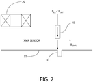
- a pancake coil based ECT probe does a spatial integration of the time rate of change of all three axes of magnetic flux leakage at any point in space created by perturbation of the eddy current distribution by a discontinuity in the material. Because the largest vector component B ZMFL of the of the out-of-plane MFL will be the component orthogonal to the AUT, it is the most dominant component in the coils' spatial integration and thus influences most the eddy current signal response. This is best approximated by vertical sensing methodologies (in Cartesian coordinates or radial in cylindrical coordinates) that align the easy axis of the XMR sensor with this field component of the MFL as shown in Figure 2 .
- the device for eddy current based nondestructive testing of tubular structures made of electrically conductive materials
- the device includes: a plurality of excitation electromagnets having an axis of symmetry and magnetoresistive sensors having an easy axis for magnetic field sensing,
- the magnetoresistive sensors are arranged in a circular array on a single plane with said the axis aligned radially with respect to the circular pattern and the electromagnets are arranged in a circular pattern on both sides of the plane with their axes of symmetry being arranged parallel to the plane and orthogonal to radii of the circular pattern on which the electromagnets are placed.
- the magnetoresistive sensors are either anisotropic magnetoresistive or giant magnetoresistive sensing elements.
- the excitation electromagnets are wound on coils having a substantially rectangular cross section with four faces and wherein the electromagnets are arranged with one of their faces aligned along at the perimeter of the circular pattern.
- the sensors are mounted between a pair of parallel circular printed circuit boards, the electromagnets are mounted on opposite faces of the printed circuit boards from the sensors and electrical connections to the sensors and the electromagnets are made through the printed circuit boards.
- the excitation electromagnets are arranged to be energized individually.
- a subset of the excitation electromagnets are excited together to create a continuous azimuthally orientated eddy current distribution an area under test.
- a subset of the excitation electromagnets are excited together and a second subset are not excited so as to create an axially oriented eddy current distribution to an area under test.
- the electromagnets are arranged in a substantially staggered pattern such that no two electromagnets on either side of said circular plane are directly opposite each other.
- a device for eddy current based nondestructive testing of an article made of electrically conductive materials which includes: a plurality of excitation electromagnets, each having an axis of symmetry and magnetoresistive sensors having an easy axis for magnetic field sensing.
- the excitation electromagnets are arranged to induce an eddy current in the article and the magnetoresistive sensors are arranged such that the easy axis is substantially orthogonal to the axis of symmetry.
- the excitation electromagnets are wound on coils having a substantially rectangular cross section with four faces and wherein said electromagnets are arranged with one of their faces aligned to be substantially parallel to a surface of the article, while the sensor are arranged with their easy axes substantially orthogonal do the surface.
- the magnetoresistive sensors are either anisotropic magnetoresistive or giant magnetoresistive sensing elements.
- the method includes the steps of: inducing an eddy current in the article, the eddy current having a direction; sensing the eddy current with either anisotropic magnetoresistive or giant magnetoresistive sensing elements, the sensing elements having an easy axis for magnetic field sensing; and aligning the sensing elements with the easy axis substantially orthogonal to the eddy current direction so as to sense any magnetic flux caused by flaws in the article.
- the article is a tube and the direction is either an axial direction or a circumferential direction.
- the sensing elements in a circular pattern in one plane at the perimeter of a cylindrical probe with said easy axis arranged in a radial direction.
- the excitation coils are arranged around the perimeter on either side of the plane of sensing elements.
- ECT eddy current testing
- a novel configuration of square or rectangular eddy current excitation coils and anisotropic magnetoresistive (AMR) or giant magnetoresistive (GMR) sensors is used to perform an ECT.
- AMR sensors and GMR sensors are referred to as "XMR" sensors in this submission.
- the present invention multiplexes square or rectangular drive coils (410 - 422) as well as XMR sensors sandwiched between two printed circuit boards 427, 428 to sense of both axial and circumferential flaws within the conductive material volume. This is accomplished by creating an excitation magnetic field distribution used to generate the desired eddy current field in the AUT with regions containing no radial component B r of the excitation field.
- the XMR elements 423 are positioned in these regions of no B r , with the sensing or "easy" axis radially aligned as shown by the arrows in Figure 7 , thus not interfering with the ability to sense the magnetic field of interest due to sensor saturation.
- the inventive sensor requires no flux-focusing lens or shielding object to magnetically separate the XMR sensor from the excitation field to prevent saturation by the excitation field.
- the information acquired via radial sensing will contain traditional in-phase and quadrature (I/Q) information with a signal morphology that is closest to that generated in contemporary wound coil based eddy current testing due to the orientation of the sensor easy axis with the radial component of the AUT MFL.
- a novel orientation and array distribution of square or rectangular drive coils 410-422 and silicon die level XMR sensing elements 423 are distributed on printed circuit boards 427, 428 as surface mounted devices and subsequently embodied into and ECT probe for tubular material inspection.
- This configuration of XMR to the surface of the AUT does not lead to the same signal morphology in response to a material defect as a wound pancake inductive coil ECT probe.
- Signal morphology is a critical ECT product requirement as there is often continuity required with historic inspection data.
- a pancake coil based ECT probe does a spatial integration of the time rate of change of all three axes of magnetic flux leakage at any point in space created by perturbation of the eddy current distribution by a discontinuity in the material. Because the largest vector component of the of the out-of-plane MFL will be the component orthogonal to the AUT, it is the most dominant component in the coils' spatial integration and thus influences most the EC signal response. This is best approximated by vertical sensing methodologies (in Cartesian coordinates or radial in cylindrical coordinates) that aligns the easy axis of the XMR sensor with this field component of the MFL.
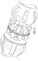
- an embodiment of the invention uses an array of XMR sensing elements 423 and inductive wound excitation coils 410, 411 etc. distributed onto a printed circuit board 427, 428 and embodied in a cylindrical probe housing Fig 4 . to sense magnetic flux leakage caused by a discontinuity or flaw in the material in a given AUT.
- the individual XMR sensors 423 will have their easy axis oriented radially with respect to the cylindrical orientation of the AUT with respect to the probe as shown by the arrows in Figure 7 .
- This invention will create a distribution of excitation coils and sensing elements that will have minimized interaction between the sensor and the excitation field without necessitating magnetic shielding or flux concentrators in the AUT.
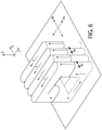
- the excitation coils are square or rectangular to create magnetic fields B X , B Y with controlled vector orientations to optimize sensor sensitivity via minimization of the impinging background excitation field.
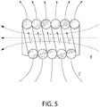
- This is in contrast to a prior art circularly wound coil as shown in Figure 5 .
- Prior art methodology as shown in Figure 1 is to place the XMR sensor 10 in the center of the drive coil 20 with the sensitive axis shown by the arrow orthogonal to the excitation field. This limits the sensor to horizontal sensing and limits spatial resolution as well, since the excitation coil geometry becomes the array resolution constraint.
- the excitation coil and the sensor can be physically separated thus creating a spatial resolution only constrained by the sensor die size.
- a plurality of multi-turn square or rectangular excitation coils are oriented orthogonally to the surface (the axis of coil symmetry orthogonal to the surface normal) of inspection oriented in a manner that will individually generate a dipole magnetic field and a subsequent eddy current distribution underneath (this pattern is very similar to that generated by a D-coil pencil probe or D-shaped planar coil).
- a typical response in a material under test is shown in Figure 8 .
- An array of square or rectangular drive coils oriented with respect to a distribution of XMR sensing elements illustrated in Figures 3 and 6 can be configured to stimulate both axial as well as circumferential flaw sensing eddy current vectors in the AUT when sequentially fired via multiplexing circuitry.
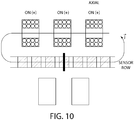
- Coils energized as shown in Figure 10 will create the necessary eddy current distribution for axial flaw (direction of black bar in Fig. 10 ) sensing by simultaneous actuation of sets of coils around the circumference.
- axial flaw direction of black bar in Fig. 10
- ⁇ azimuthal angle
- Coils energized as shown in Figure 10 will create the necessary eddy current distribution for axial flaw (direction of black bar in Fig. 10 ) sensing by simultaneous actuation of sets of coils around the circumference.
- current is supplied to excitation coils on one side of the sensor row simultaneously and equally activated. This simultaneous activation of coils will create a continuous azimuthally orientated eddy current distribution the area under test.
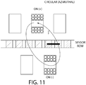
- Coils energized as shown in Figure 11 create the necessary axial orientation of eddy currents for sensing circumferential flaws in a cylindrical area under test. Note that in this mode, the coils are energized to create opposing directions of current j.
- off-the-surface sensing via XMR can be performed by incorporation of drive coils that have enough amp-turns to create an adequate signal-to-noise ratio in the sensed MFL.
- This distribution of same directional current carrying wires in excitation coils creates a region that has a longitudinal magnetic field and zero transverse magnetic field (along the direction of the current carrying wire) external to the solenoid face. This region will have no Br in cylindrical coordinates.
- This coil arrangement allows both axial as well as circumferential eddy current distribution; and (b) the array configuration allows for regions of zero (or significantly reduced) excitation Br, thereby allowing the efficient use and placement of the XMR elements for vertical (radial) sensing of magnetic flux leakage field due to the flaw of interest.
- Utilization of XMR sense elements as described herein will have the following useful aspects. It will increase spatial resolution in the pick-up array via individual sensing elements that are on the order of 0.5mm to 1mm in width at the silicon die level. It will also increase inspection sensitivity as these sensors have an increased sensitivity over wound pancake coil receive sensors. It will also increase image quality in a multi-frequency scan due to XMR sensor sensitivity not being a function of the frequency of magnetic field sensed (versus prior art inductive sensing elements). It will provide the ability of vertical (radial for tubular applications) XMR sensing allowing the use of an XMR sensing element to best approximate the signal morphology created by a wound pancake coil receiver. It will enable axial as well as circumferential flaw sensing and characterization. It will enable off-the-surface (non-contact) sensing. In addition, no shielding of the XMR sensor from the excitation signal is necessary.
- Utilization of the novel drive coil configuration in this submission will: Generate eddy currents with a net directional vector that is in the Z direction (in cylindrical coordinates) for circumferential indication detection; generate eddy currents with a net directional vector that is on the azimuthally oriented (in cylindrical coordinates) for axial indication detection; and allow the use of XMR sensors in close proximity of the drive coil without saturation.
- Operation of the present invention may be as follows: Uni-directional XMR sensors are placed between the excitation coils in a manner outlined in above and shown in Figure 3 .
- the sensing element will be oriented between the excitation coils with the sensor easy axis oriented orthogonally to the area under test. For a cylindrical application (tube inspection) this would be in the radial direction as shown in Figure 7 .
- Excitation coils and sensors in the proximity of the area of interest can be activated to execute material inspection in this region.
- the array of sensors and excitation coils can be processed in groups to cover the entire area under test for either axial or circumferential flaw detection.
- coils 421 and 424 can be activated as shown in Figure 11 and resulting eddy currents sensed. Then coils 420 and 413 can be activated. Next coils 419 and 426, and so on to cover the entire circumference of the sensor. Similarly staged sets of coils as shown in Fig. 10 on one side of the sensor row (e.g. 421, 420, 419 then 420, 419, 418 etc.) can be sequentially energized for sensing axial flaws.
- This embodiment will use vertical (or radial in cylindrical coordinates) sensing to best approximate the signal response of an inductive wound coil magnetic sensor currently and most commonly used in eddy current testing (ECT).
- ECT eddy current testing
Landscapes
- Physics & Mathematics (AREA)
- Chemical & Material Sciences (AREA)
- General Physics & Mathematics (AREA)
- Health & Medical Sciences (AREA)
- Chemical Kinetics & Catalysis (AREA)
- Electrochemistry (AREA)
- Life Sciences & Earth Sciences (AREA)
- Analytical Chemistry (AREA)
- Biochemistry (AREA)
- General Health & Medical Sciences (AREA)
- Immunology (AREA)
- Pathology (AREA)
- Condensed Matter Physics & Semiconductors (AREA)
- Investigating Or Analyzing Materials By The Use Of Magnetic Means (AREA)
Description
- This utility application claims the benefit under 35 U.S.C. §119(e) of provisional application serial number
61/813,899 filed on April 19, 2013 - The invention is directed to sensor probes for eddy current non-destructive testing and, in particular, to such probes employing magnetoresistive sensors.
- Nondestructive evaluation (NDE) technologies have been recently challenged to find material defects such as fatigue flaws, cracks and damage precursors such as stress or corrosion induced local conductivity variation in structures with higher probability of detection (POD) and a level of improvement is necessary as these issues are critical to operational safety. Certain inspection opportunities and their specific geometries often necessitate off-the-surface or non-contact methodologies thereby eliminating methods such as ultrasound testing where either physical contact or a transmit medium necessary for inspection. The non-destructive testing industry currently does most non-contact inspection of conductive materials via conventional wound inductive coil based eddy current inspection techniques. These inspections have limited spatial resolution due to sense coil size as well as frequency dependent sensitivity and thus have limited efficacy.
- Eddy current testing (ECT) probes to locate and characterize flaws or material defects in a conductive material are known. An ECT probe does this by sensing the out-of-plane magnetic flux leakage (MFL) created by the deviation of eddy currents by the flaws or defects in the area under test (AUT).
- Technological advancements in the manufacturing of these elements have led to commercially accessible sensing elements. Low cost anisotropic magnetoresistance AMR and giant magnetoresistive GMR magnetometers (referred to collectively as "XMR" sensors herein) are now available which are sensitive, have small package size, consume little power, and operate at room temperature.
- ECT utilizing XMR sensing can have a higher level of utility, as these sensing elements are non-inductive and orders of magnitude smaller than traditional eddy current coils. A magnetoresistive (MR) sensor is a solid-state device that utilizes electron conduction physics to convert a magnetic field into an electrical signal. Anisotropic magnetoresistance (AMR), for example, is a solid-state sensing element that has a permalloy (Ni80-Fe20) electrodeposited line on silicon for sensing low-level magnetic fields. This occurs by an alignment of the material's magnetic domains in response to the external magnetic field of interest. This magnetic domain alignment changes the resistivity of the sensor via induced changes in the scattering matrix (spin-coupled interaction between the conduction electrons and the magnetic moments in the material)). In contrast a magnetic sensor exhibiting the giant magnetoresistive (GMR) mechanism will convert a sensed magnetic field to an electrical signal is exploiting the spin-coupled charge interaction of a multi-layer structure. This structure is a three-ply stack of a ferromagnetic material (FM), a non-magnetic conductive layer (NM) and a bottom layer of ferromagnetic material (FM) all on a silicon substrate.
- One of the challenges with XMR sensors is that they have no means of discriminating magnetic fields sensed along the easy axis. Because the level of the field of interest will be orders of magnitude lower than the background drive magnetic field, it has been historic precedent to either: (a) shield the sensor from the drive field or (b) orient the sensor such that the sensitive axis is orthogonal to the drive field as to not saturate the sensing element. For example, one can find the use of concentric/co-located sensors and drives in US patents:
US6888346 ,2011/0068784 A1 ,2005/0007108 A1 ,US6888346 as well as2005/0007108 A1 . All of the documents cited herein are incorporated by reference in their entireties. This has led to the vast majority of embodied XMR based ECT probes towards using the sensor in a horizontal sensing configuration with respect to the AUT while positioned in the center of an excitation
coil. As illustrated inFigure 1 , this allows thesensor 10 to be co-located with thedrive coil 20 and positioned in the bore of the coil orienting the excitation field BEX orthogonally to the sensor easy axis. Therefore the sensor would be immune to the excitation field. - This configuration of
XMR 10 to the surface of theAUT 30 does not lead to the same signal morphology in response to amaterial defect 31 as a wound pancake inductive coil ECT probe. Signal morphology is a critical ECT product requirement as there is often continuity required with historic inspection data. A pancake coil based ECT probe does a spatial integration of the time rate of change of all three axes of magnetic flux leakage at any point in space created by perturbation of the eddy current distribution by a discontinuity in the material. Because the largest vector component BZMFL of the of the out-of-plane MFL will be the component orthogonal to the AUT, it is the most dominant component in the coils' spatial integration and thus influences most the eddy current signal response. This is best approximated by vertical sensing methodologies (in Cartesian coordinates or radial in cylindrical coordinates) that align the easy axis of the XMR sensor with this field component of the MFL as shown inFigure 2 . - Because of the aforementioned reasons, to date, there has not been a practicable ECT probe that orients an XMR sensor with the easy axis aligned orthogonal to the surface of the AUT.
Further eddy current testing devices are disclosed inJP 2006/322 860 A US 3 875 502 A , wherein one single excitation coil is combined with a plurality of sensor elements. - In an embodiment of the invention, according to
claim 1, there is device for eddy current based nondestructive testing of tubular structures made of electrically conductive materials wherein the device includes: a plurality of excitation electromagnets having an axis of symmetry and magnetoresistive sensors having an easy axis for magnetic field sensing, The magnetoresistive sensors are arranged in a circular array on a single plane with said the axis aligned radially with respect to the circular pattern and the electromagnets are arranged in a circular pattern on both sides of the plane with their axes of symmetry being arranged parallel to the plane and orthogonal to radii of the circular pattern on which the electromagnets are placed. In a further embodiment, the magnetoresistive sensors are either anisotropic magnetoresistive or giant magnetoresistive sensing elements. In a further embodiment, the excitation electromagnets are wound on coils having a substantially rectangular cross section with four faces and wherein the electromagnets are arranged with one of their faces aligned along at the perimeter of the circular pattern. In a further embodiment, the sensors are mounted between a pair of parallel circular printed circuit boards, the electromagnets are mounted on opposite faces of the printed circuit boards from the sensors and electrical connections to the sensors and the electromagnets are made through the printed circuit boards. In a further embodiment, the excitation electromagnets are arranged to be energized individually. In a further embodiment, a subset of the excitation electromagnets are excited together to create a continuous azimuthally orientated eddy current distribution an area under test. In a further embodiment, a subset of the excitation electromagnets are excited together and a second subset are not excited so as to create an axially oriented eddy current distribution to an area under test. In a further embodiment, the electromagnets are arranged in a substantially staggered pattern such that no two electromagnets on either side of said circular plane are directly opposite each other. - In an example of the invention there is a device for eddy current based nondestructive testing of an article made of electrically conductive materials, which includes: a plurality of excitation electromagnets, each having an axis of symmetry and magnetoresistive sensors having an easy axis for magnetic field sensing. The excitation electromagnets are arranged to induce an eddy current in the article and the magnetoresistive sensors are arranged such that the easy axis is substantially orthogonal to the axis of symmetry. In a further embodiment, the excitation electromagnets are wound on coils having a substantially rectangular cross section with four faces and wherein said electromagnets are arranged with one of their faces aligned to be substantially parallel to a surface of the article, while the sensor are arranged with their easy axes substantially orthogonal do the surface. In a further embodiment, the magnetoresistive sensors are either anisotropic magnetoresistive or giant magnetoresistive sensing elements.
- In an embodiment of the invention, according to claim 9, there is a method of non-destructively testing an article made of electrically conductive material. The method includes the steps of: inducing an eddy current in the article, the eddy current having a direction; sensing the eddy current with either anisotropic magnetoresistive or giant magnetoresistive sensing elements, the sensing elements having an easy axis for magnetic field sensing; and aligning the sensing elements with the easy axis substantially orthogonal to the eddy current direction so as to sense any magnetic flux caused by flaws in the article. In a further embodiment, the article is a tube and the direction is either an axial direction or a circumferential direction. In a further embodiment, the sensing elements in a circular pattern in one plane at the perimeter of a cylindrical probe with said easy axis arranged in a radial direction. Ina further embodiment, the excitation coils are arranged around the perimeter on either side of the plane of sensing elements.
-
-
Figure 1 is a diagram of a prior art eddy current testing probe showing an XMR sensor with easy axis parallel to BEX; -
Figure 2 is a diagram of an area under test with an XMR sensor aligned orthogonal to BZMFL; -
Figure 3 is a 3D view of an exemplary ECT probe sensor and excitation coil assembly; -
Figure 4 is a 3D view of an exemplary ECT probe including the assembly ofFig. 3 ; -
Figure 5 is a diagram of a prior art excitation coil; -
Figure 6 is a diagram of an exemplary coil having a square bobbin shape; -
Figure 7 is a diagram of an exemplary sensor array; -
Figure 8 is a diagram of an exemplary eddy current vector in an area under test; -
Figure 9 is diagram of sequenced blocks of eddy current excitation coils as viewed around the perimeter of an exemplary probe such as is shown inFig. 3 ; -
Figure 10 is a diagram of an excitation mode for an exemplary block of coils to create a circumferential eddy current flow to sense an axial flaw; and -
Figure 11 is a diagram of an excitation mode for an exemplary block of coils to create an axial eddy current flow to sense a circumferential flaw. - The invention will be illustrated in more detail with reference to the following embodiments, but it should be understood that the present invention is not deemed to be limited thereto.
- The following exemplary eddy current testing (ECT) probe will locate and characterize flaws or material defects in a conductive material. A novel configuration of square or rectangular eddy current excitation coils and anisotropic magnetoresistive (AMR) or giant magnetoresistive (GMR) sensors is used to perform an ECT. AMR sensors and GMR sensors are referred to as "XMR" sensors in this submission.
- With reference to
Fig. 3 , in an embodiment, the present invention multiplexes square or rectangular drive coils (410 - 422) as well as XMR sensors sandwiched between two printedcircuit boards Fig. 7 , theXMR elements 423 are positioned in these regions of no Br, with the sensing or "easy" axis radially aligned as shown by the arrows inFigure 7 , thus not interfering with the ability to sense the magnetic field of interest due to sensor saturation. - Due to this novel design attribute, the inventive sensor requires no flux-focusing lens or shielding object to magnetically separate the XMR sensor from the excitation field to prevent saturation by the excitation field. The information acquired via radial sensing will contain traditional in-phase and quadrature (I/Q) information with a signal morphology that is closest to that generated in contemporary wound coil based eddy current testing due to the orientation of the sensor easy axis with the radial component of the AUT MFL.
- In an embodiment illustrated in
Figures 3 ,4 and7 , a novel orientation and array distribution of square or rectangular drive coils 410-422 and silicon die levelXMR sensing elements 423 are distributed on printedcircuit boards - This configuration of XMR to the surface of the AUT does not lead to the same signal morphology in response to a material defect as a wound pancake inductive coil ECT probe. Signal morphology is a critical ECT product requirement as there is often continuity required with historic inspection data. A pancake coil based ECT probe does a spatial integration of the time rate of change of all three axes of magnetic flux leakage at any point in space created by perturbation of the eddy current distribution by a discontinuity in the material. Because the largest vector component of the of the out-of-plane MFL will be the component orthogonal to the AUT, it is the most dominant component in the coils' spatial integration and thus influences most the EC signal response. This is best approximated by vertical sensing methodologies (in Cartesian coordinates or radial in cylindrical coordinates) that aligns the easy axis of the XMR sensor with this field component of the MFL.
- As shown in
Figures 3 and6 , an embodiment of the invention uses an array ofXMR sensing elements 423 and inductive wound excitation coils 410, 411 etc. distributed onto a printedcircuit board Fig 4 . to sense magnetic flux leakage caused by a discontinuity or flaw in the material in a given AUT. Theindividual XMR sensors 423 will have their easy axis oriented radially with respect to the cylindrical orientation of the AUT with respect to the probe as shown by the arrows inFigure 7 . This invention will create a distribution of excitation coils and sensing elements that will have minimized interaction between the sensor and the excitation field without necessitating magnetic shielding or flux concentrators in the AUT. - In an embodiment shown in
Figure 6 , the excitation coils are square or rectangular to create magnetic fields BX, BY with controlled vector orientations to optimize sensor sensitivity via minimization of the impinging background excitation field. This is in contrast to a prior art circularly wound coil as shown inFigure 5 . Prior art methodology as shown inFigure 1 is to place theXMR sensor 10 in the center of thedrive coil 20 with the sensitive axis shown by the arrow orthogonal to the excitation field. This limits the sensor to horizontal sensing and limits spatial resolution as well, since the excitation coil geometry becomes the array resolution constraint. By optimization of the excitation field and creating controlled regions of no excitation field, the excitation coil and the sensor can be physically separated thus creating a spatial resolution only constrained by the sensor die size. - In an embodiment, a plurality of multi-turn square or rectangular excitation coils are oriented orthogonally to the surface (the axis of coil symmetry orthogonal to the surface normal) of inspection oriented in a manner that will individually generate a dipole magnetic field and a subsequent eddy current distribution underneath (this pattern is very similar to that generated by a D-coil pencil probe or D-shaped planar coil). A typical response in a material under test is shown in
Figure 8 . An array of square or rectangular drive coils oriented with respect to a distribution of XMR sensing elements illustrated inFigures 3 and6 can be configured to stimulate both axial as well as circumferential flaw sensing eddy current vectors in the AUT when sequentially fired via multiplexing circuitry. Coils energized as shown inFigure 10 will create the necessary eddy current distribution for axial flaw (direction of black bar inFig. 10 ) sensing by simultaneous actuation of sets of coils around the circumference. For "circumferential" (azimuthal angle ϕ) eddy current generation in the AUT, current is supplied to excitation coils on one side of the sensor row simultaneously and equally activated. This simultaneous activation of coils will create a continuous azimuthally orientated eddy current distribution the area under test. - Coils energized as shown in
Figure 11 , i.e. on opposite sides of the sensor row, create the necessary axial orientation of eddy currents for sensing circumferential flaws in a cylindrical area under test. Note that in this mode, the coils are energized to create opposing directions of current j. - In a further embodiment, off-the-surface sensing via XMR can be performed by incorporation of drive coils that have enough amp-turns to create an adequate signal-to-noise ratio in the sensed MFL.
- This distribution of same directional current carrying wires in excitation coils creates a region that has a longitudinal magnetic field and zero transverse magnetic field (along the direction of the current carrying wire) external to the solenoid face. This region will have no Br in cylindrical coordinates. There are two novel attributes to this coil arrangement: (a) it allows both axial as well as circumferential eddy current distribution; and (b) the array configuration allows for regions of zero (or significantly reduced) excitation Br, thereby allowing the efficient use and placement of the XMR elements for vertical (radial) sensing of magnetic flux leakage field due to the flaw of interest.
- While the invention has been illustrated and described in connection with currently preferred embodiments shown and described in detail, it is not intended to be limited to the details shown since various modifications and structural changes may be made without departing in any way from the spirit of the present invention. The embodiments were chosen and described in order to best explain the principles of the invention and various embodiments with various modifications as are suited to the particular use contemplated.
- Utilization of XMR sense elements as described herein will have the following useful aspects. It will increase spatial resolution in the pick-up array via individual sensing elements that are on the order of 0.5mm to 1mm in width at the silicon die level. It will also increase inspection sensitivity as these sensors have an increased sensitivity over wound pancake coil receive sensors. It will also increase image quality in a multi-frequency scan due to XMR sensor sensitivity not being a function of the frequency of magnetic field sensed (versus prior art inductive sensing elements). It will provide the ability of vertical (radial for tubular applications) XMR sensing allowing the use of an XMR sensing element to best approximate the signal morphology created by a wound pancake coil receiver. It will enable axial as well as circumferential flaw sensing and characterization. It will enable off-the-surface (non-contact) sensing. In addition, no shielding of the XMR sensor from the excitation signal is necessary.
- Utilization of the novel drive coil configuration in this submission will: Generate eddy currents with a net directional vector that is in the Z direction (in cylindrical coordinates) for circumferential indication detection; generate eddy currents with a net directional vector that is on the azimuthally oriented (in cylindrical coordinates) for axial indication detection; and allow the use of XMR sensors in close proximity of the drive coil without saturation.
- Operation of the present invention may be as follows:
Uni-directional XMR sensors are placed between the excitation coils in a manner outlined in above and shown inFigure 3 . The sensing element will be oriented between the excitation coils with the sensor easy axis oriented orthogonally to the area under test. For a cylindrical application (tube inspection) this would be in the radial direction as shown inFigure 7 . Excitation coils and sensors in the proximity of the area of interest can be activated to execute material inspection in this region. The array of sensors and excitation coils can be processed in groups to cover the entire area under test for either axial or circumferential flaw detection. For example, with reference toFigure 3 , coils 421 and 424 can be activated as shown inFigure 11 and resulting eddy currents sensed. Then coils 420 and 413 can be activated.Next coils Fig. 10 on one side of the sensor row (e.g. 421, 420, 419 then 420, 419, 418 etc.) can be sequentially energized for sensing axial flaws. - For circumferential eddy current generation in the AUT to sense axial flaws as shown in
Fig. 10 , current is supplied to banks of excitation coils on one side of the sensor row. These banks of coils will be simultaneously and equally activated. These banks will then be multiplexed and sequentially driven to encompass the area under test as shown inFig. 10 . - For sensing a circumferential (azimuthal angle ϕ) flaw in the AUT, current is supplied to excitation coils on opposite sides of the sensors. The coils are simultaneously activated to create opposite field directions as shown in
Fig. 11 , wherein the black horizontal bar indicates the orientation of a flaw. This simultaneous activation of coils across the sensor row will create a continuous azimuthally orientated eddy current distribution the area under test. - These eddy currents when perturbed by a material discontinuity (flaw, crack, variation in crystal structure, variation in material phase resulting in a permeability variation) will create a variation in the reciprocal magnetic field. This magnetic field directly associated with the eddy current is sensed via the XMR sensor to create a direct mapping of the magnetic field variation in an area of interest. From these variations intelligence regarding flaw, crack, and variation in crystal structure, variation in material phase resulting in permeability variations can be inferred.
- This embodiment will use vertical (or radial in cylindrical coordinates) sensing to best approximate the signal response of an inductive wound coil magnetic sensor currently and most commonly used in eddy current testing (ECT).
- While the invention has been described in detail and with reference to specific examples thereof, it will be apparent to one skilled in the art that various changes and modifications can be made therein without departing from the spirit and scope thereof.
Claims (12)
- A device for eddy current based non-destructive testing of an article made of electrically conductive materials comprising:an excitation coil assembly, anda plurality of magnetoresistive sensors (423) each having a sensing axis for magnetic field sensing; wherein said excitation coil assembly comprises a plurality of excitation electromagnets (410 - 426) having an axis of cylindrical symmetry, whereinsaid excitation electromagnets (410 - 426) are arranged to induce an eddy current in the article, andsaid magnetoresistive sensors (423) are arranged such that said sensing axis is substantially orthogonal to said axis of symmetry, characterized in thatsaid magnetoresistive sensors (423) are arranged in a circular array on a single plane with said sensing axis aligned radially with respect to said circular pattern, andsaid electromagnets (410 - 426) are arranged in a circular pattern on both sides of said plane with their axes of symmetry being arranged parallel to said plane and orthogonal to radii of said circular pattern on which said electromagnets (410 - 426) are placed.
- The device of Claim 1, wherein said magnetoresistive sensors (423) are either anisotropic magnetoresistive or giant magnetoresistive sensing elements.
- The device of Claim 1, wherein said excitation electromagnets (410 - 426) are wound on coils having a substantially rectangular cross section with four faces and wherein said electromagnets (410 - 426) are arranged with one of their faces aligned along at the perimeter of said circular pattern.
- The device of Claim 1, wherein said sensors (423) are mounted between a pair of parallel circular printed circuit boards (427, 428), said electromagnets (410 - 426) are mounted on opposite faces of said printed circuit boards (427, 428) from said sensors (423) and wherein electrical connections to said sensors (423) and said electromagnets (410 - 426) are made through said printed circuit boards (427, 428).
- The device of Claim 1, wherein said excitation electromagnets (410 - 426) are arranged to be energized individually.
- The device of Claim 1, wherein a subset of said excitation electromagnets (410 - 426) are arranged to be excited together to create a continuous azimuthally orientated eddy current distribution an area under test (30).
- The device of Claim 1, wherein a subset of said excitation electromagnets (410 - 426) are arranged to be excited together to create an axially oriented eddy current distribution to an area under test (30).
- The device of Claim 1, wherein said electromagnets (410 - 426) are arranged in a substantially staggered pattern such that no two electromagnets (410 - 426) on either side of said circular plane are directly opposite each other.
- A method of non-destructively testing an article made of electrically conductive material, using the device for eddy current based non-destructive testing of one of the foregoing claims, comprising:inducing an eddy current in said article, said eddy current having a direction; andsensing said eddy current with either anisotropic magnetoresistive or giant magnetoresistive sensing elements, said sensing elements having a sensing axis magnetic field sensing; andaligning said sensing elements with said sensing axis substantially orthogonal to said eddy current direction so as to sense any magnetic flux caused by flaws in the article.
- The method of Claim 9, wherein said article is a tube and said direction is either an axial direction or a circumferential direction.
- The method of Claim 10, further comprising arranging said sensing elements in a circular pattern in one plane at the perimeter of a cylindrical probe with said sensing axis arranged in a radial direction.
- The method of Claim 11, further comprising arranging excitation coils around said perimeter on either side of said plane of sensing elements.
Priority Applications (1)
| Application Number | Priority Date | Filing Date | Title |
|---|---|---|---|
| HRP20181721TT HRP20181721T1 (en) | 2013-04-19 | 2014-04-17 | Eddy current inspection probe based on magnetoresistive sensors |
Applications Claiming Priority (2)
| Application Number | Priority Date | Filing Date | Title |
|---|---|---|---|
| US201361813899P | 2013-04-19 | 2013-04-19 | |
| PCT/US2014/034479 WO2014172531A1 (en) | 2013-04-19 | 2014-04-17 | Eddy current inspection probe based on magnetoresistive sensors |
Publications (2)
| Publication Number | Publication Date |
|---|---|
| EP2986979A1 EP2986979A1 (en) | 2016-02-24 |
| EP2986979B1 true EP2986979B1 (en) | 2018-07-25 |
Family
ID=50721919
Family Applications (1)
| Application Number | Title | Priority Date | Filing Date |
|---|---|---|---|
| EP14723960.2A Active EP2986979B1 (en) | 2013-04-19 | 2014-04-17 | Eddy current inspection probe based on magnetoresistive sensors |
Country Status (4)
| Country | Link |
|---|---|
| US (2) | US20160084800A1 (en) |
| EP (1) | EP2986979B1 (en) |
| HR (1) | HRP20181721T1 (en) |
| WO (1) | WO2014172531A1 (en) |
Families Citing this family (12)
| Publication number | Priority date | Publication date | Assignee | Title |
|---|---|---|---|---|
| US20160084800A1 (en) * | 2013-04-19 | 2016-03-24 | Jevne Branden Micheau-Cunningham | Eddy current inspection probe based on magnetoresistive sensors |
| CN105806929A (en) * | 2014-12-30 | 2016-07-27 | 中核武汉核电运行技术股份有限公司 | Ferromagnetic thin-walled tube circumferential AC magnetization magnetic flux leakage detection array probe |
| US10067256B2 (en) | 2015-03-26 | 2018-09-04 | General Electric Company | Proximity probe interchange compensation |
| BR112018007210A2 (en) * | 2015-11-12 | 2018-10-16 | Halliburton Energy Services Inc | method, apparatus, and system for defect evaluation using holographic images. |
| MA41539A (en) * | 2015-11-25 | 2017-12-26 | Vayyar Imaging Ltd | METHODS AND APPARATUS FOR COLLOCATION OF ELECTROMAGNETIC COILS AND ELECTRONIC CIRCUITS |
| CA3014663A1 (en) * | 2016-02-19 | 2017-08-24 | Zetec, Inc. | Eddy current inspection probe |
| WO2019083923A1 (en) * | 2017-10-23 | 2019-05-02 | Tech4Imaging Llc | Differential magnetic field tomography |
| EP3779487B1 (en) * | 2019-08-14 | 2023-07-19 | TE Connectivity Sensors Germany GmbH | Assembly and method for determining the strength of a magnetic stray field |
| JP2023124388A (en) * | 2022-02-25 | 2023-09-06 | Tdk株式会社 | magnetic sensor |
| CN114720556A (en) * | 2022-03-30 | 2022-07-08 | 中国民航大学 | Flat-cut sensor probe and scanning detection method for defect detection of CFRP laminates |
| CN219369648U (en) * | 2022-08-22 | 2023-07-18 | 华能(福建漳州)能源有限责任公司 | Leakage magnetic detection teaching aid device based on LabVIEW |
| CN117781839A (en) * | 2023-12-27 | 2024-03-29 | 西北工业大学 | Multifunctional sensor and monitoring method integrating strain and crack monitoring functions |
Family Cites Families (42)
| Publication number | Priority date | Publication date | Assignee | Title |
|---|---|---|---|---|
| SE347356B (en) * | 1970-03-20 | 1972-07-31 | Essem Metotest Ab | |
| US3875502A (en) | 1973-05-24 | 1975-04-01 | Foerster Inst Dr Friedrich | Coil arrangement and circuit for eddy current testing |
| US5929636A (en) | 1996-05-02 | 1999-07-27 | Integrated Magnetoelectronics | All-metal giant magnetoresistive solid-state component |
| US5696449A (en) * | 1996-06-03 | 1997-12-09 | General Electric Company | RF coil for open MR magnet |
| US6822443B1 (en) | 2000-09-11 | 2004-11-23 | Albany Instruments, Inc. | Sensors and probes for mapping electromagnetic fields |
| US6150809A (en) | 1996-09-20 | 2000-11-21 | Tpl, Inc. | Giant magnetorestive sensors and sensor arrays for detection and imaging of anomalies in conductive materials |
| JP3941082B2 (en) * | 1998-01-28 | 2007-07-04 | 株式会社安川電機 | Magnetic detector |
| US6577121B1 (en) * | 1998-11-11 | 2003-06-10 | Koninklijke Philips Electronics N.V. | Magnetoresistive sensor for measuring relative displacement of construction parts |
| US6448773B1 (en) * | 2000-02-24 | 2002-09-10 | Toshiba America Mri, Inc. | Method and system for measuring and compensating for eddy currents induced during NMR imaging operations |
| US6504363B1 (en) * | 2000-03-07 | 2003-01-07 | Teodor Dogaru | Sensor for eddy current testing and method of use thereof |
| US6992482B2 (en) * | 2000-11-08 | 2006-01-31 | Jentek Sensors, Inc. | Magnetic field sensor having a switchable drive current spatial distribution |
| US6888346B2 (en) * | 2000-11-28 | 2005-05-03 | The United States Of America As Represented By The Administrator Of The National Aeronautics And Space Administration | Magnetoresistive flux focusing eddy current flaw detection |
| FR2831667B1 (en) | 2001-10-29 | 2004-04-23 | Cegelec | SENSOR FOR DETECTING FAULTS IN A WORKPIECE |
| US7054118B2 (en) | 2002-03-28 | 2006-05-30 | Nve Corporation | Superparamagnetic field sensing devices |
| US7411390B2 (en) * | 2002-06-04 | 2008-08-12 | Jentek Sensors, Inc. | High resolution inductive sensor arrays for UXO |
| US20050007108A1 (en) | 2003-07-11 | 2005-01-13 | Teodor Dogaru | Probes and methods for detecting defects in metallic structures |
| CA2499525C (en) * | 2004-03-11 | 2012-11-27 | Smith International, Inc. | Casing brush assembly |
| US7250757B1 (en) | 2004-09-16 | 2007-07-31 | Radiation Monitoring Devices, Inc. | Apparatus and method for circuit analysis using magnetic and electromagnetic stimulation of the circuit for dual magnetic field imaging |
| JP4323437B2 (en) | 2005-01-12 | 2009-09-02 | 株式会社日立製作所 | Eddy current flaw detection probe and eddy current flaw detection device |
| JP2006322860A (en) | 2005-05-20 | 2006-11-30 | Marktec Corp | Eddy current flaw detection probe |
| JP4466487B2 (en) * | 2005-06-27 | 2010-05-26 | Tdk株式会社 | Magnetic sensor and current sensor |
| WO2007002302A2 (en) * | 2005-06-28 | 2007-01-04 | Wyle Laboratories, Inc. | Magnetoresistive sensor based eddy current crack finder |
| US7542871B2 (en) | 2005-10-31 | 2009-06-02 | The Boeing Company | Control for hand-held imaging array using computer mouse configuration |
| US7304474B2 (en) * | 2005-11-29 | 2007-12-04 | The Boeing Company | Eddy current inspection device with arrays of magnetoresistive sensors |
| JP4776696B2 (en) | 2006-02-24 | 2011-09-21 | コミサリア ア レネルジ アトミク | Method and apparatus for nondestructive evaluation of defects in metal objects |
| EP1996928B1 (en) | 2006-03-10 | 2018-06-27 | Bruker EAS GmbH | System and method for the nondestructive testing of elongate bodies and their weldbond joints |
| EP2084524B1 (en) * | 2006-11-01 | 2016-11-30 | Industry-academic Cooperation Foundation, Chosun University | Magnetic sensor apparatus for detecting defects |
| US7538546B2 (en) * | 2006-11-10 | 2009-05-26 | Infinitum Solutions, Inc. | In-plane magnetic field generation and testing of magnetic sensor |
| US8920613B2 (en) * | 2007-01-31 | 2014-12-30 | Applied Materials, Inc. | Offset magnet compensation for non-uniform plasma |
| EP2131205B1 (en) * | 2007-03-23 | 2018-05-02 | Asahi Kasei EMD Corporation | Magnetic sensor and its sensitivity measuring method |
| DE102007050143A1 (en) | 2007-10-19 | 2009-04-23 | Mtu Aero Engines Gmbh | Magnetic remanence measuring probe and method for detecting foreign material deposits and voids in cavities |
| US7952348B2 (en) | 2007-11-05 | 2011-05-31 | General Electric Company | Flexible eddy current array probe and methods of assembling the same |
| US8432158B2 (en) * | 2008-10-02 | 2013-04-30 | Honeywell International Inc. | Apparatus and method for determining speed and direction of slotted targets utilizing dual magnetic sensor packaging |
| US8368395B2 (en) * | 2008-12-17 | 2013-02-05 | Ndt Technologies, Inc. | Magnetic inspection device and method for detecting loss in metallic cross section |
| DE102009010453A1 (en) | 2009-02-26 | 2010-09-09 | V&M Deutschland Gmbh | Device for non-destructive testing of pipes |
| US8436608B2 (en) | 2009-09-21 | 2013-05-07 | General Electric Company | Eddy current inspection system and method |
| US9678175B2 (en) | 2010-07-26 | 2017-06-13 | Radiation Monitoring Devices, Inc. | Eddy current detection |
| US8907665B2 (en) * | 2010-11-17 | 2014-12-09 | Fbs, Inc. | Magnetostrictive sensor array for active or synthetic phased-array focusing of guided waves |
| US8717012B2 (en) | 2011-04-28 | 2014-05-06 | The United States of America as respresented by the United States National Aeronautics and Space Administration | Eddy current probe for surface and sub-surface inspection |
| US20130214771A1 (en) * | 2012-01-25 | 2013-08-22 | Radiation Monitoring Devices, Inc. | Systems and methods for inspecting structures including pipes and reinforced concrete |
| US20160084800A1 (en) * | 2013-04-19 | 2016-03-24 | Jevne Branden Micheau-Cunningham | Eddy current inspection probe based on magnetoresistive sensors |
| US9678041B2 (en) * | 2014-07-24 | 2017-06-13 | City of Tallahassee | Non-destructive real-time magnetic flux leakage imaging system and method |
-
2014
- 2014-04-17 US US14/785,514 patent/US20160084800A1/en not_active Abandoned
- 2014-04-17 WO PCT/US2014/034479 patent/WO2014172531A1/en not_active Ceased
- 2014-04-17 US US14/255,272 patent/US9784715B2/en active Active
- 2014-04-17 HR HRP20181721TT patent/HRP20181721T1/en unknown
- 2014-04-17 EP EP14723960.2A patent/EP2986979B1/en active Active
Non-Patent Citations (1)
| Title |
|---|
| None * |
Also Published As
| Publication number | Publication date |
|---|---|
| EP2986979A1 (en) | 2016-02-24 |
| US20160084800A1 (en) | 2016-03-24 |
| US20140312891A1 (en) | 2014-10-23 |
| US9784715B2 (en) | 2017-10-10 |
| WO2014172531A1 (en) | 2014-10-23 |
| HRP20181721T1 (en) | 2018-12-28 |
Similar Documents
| Publication | Publication Date | Title |
|---|---|---|
| US9784715B2 (en) | Eddy current inspection probe based on magnetoresistive sensors | |
| US6822443B1 (en) | Sensors and probes for mapping electromagnetic fields | |
| Jander et al. | Magnetoresistive sensors for nondestructive evaluation | |
| EP2390651B1 (en) | GMR biosensor with enhanced sensitivity | |
| US7952348B2 (en) | Flexible eddy current array probe and methods of assembling the same | |
| US8704513B2 (en) | Shielded eddy current coils and methods for forming same on printed circuit boards | |
| US9678175B2 (en) | Eddy current detection | |
| US9035671B2 (en) | Probe card and method for testing magnetic sensors | |
| US10634645B2 (en) | Eddy current probe with 3-D excitation coils | |
| JP3843343B2 (en) | Eddy current sensor for nondestructive inspection | |
| CN102099702B (en) | Measuring device for detecting magnetism and method of manufacturing such measuring device | |
| US8717012B2 (en) | Eddy current probe for surface and sub-surface inspection | |
| US10921287B2 (en) | Drive coil for eddy current inspection probe | |
| WO2007095971A1 (en) | Method and device for non destructive evaluation of defects in a metallic object | |
| US9322806B2 (en) | Eddy current sensor with linear drive conductor | |
| US9267921B2 (en) | Axial and circumferential flaw sensing eddy current probe | |
| Kim et al. | Integration of Hall and giant magnetoresistive sensor arrays for real-time 2-D visualization of magnetic field vectors | |
| CN118409255B (en) | Magnetization measuring sensor used under pulse strong magnetic field | |
| Smith et al. | GMR Magnetic Sensor Arrays for NDE Eddy‐Current Testing | |
| CN206147081U (en) | Low noise magnetoresistive sensor | |
| CN117825485A (en) | Defect inspection probe based on multi-channel absolute differential output | |
| Maťková et al. | Detection sensors for electromagnetic nondestructive evaluation | |
| CN118883708B (en) | Magnetic eddy current sensor and detection method | |
| CN116125355A (en) | Inspection device and inspection method for magnetic sensor |
Legal Events
| Date | Code | Title | Description |
|---|---|---|---|
| PUAI | Public reference made under article 153(3) epc to a published international application that has entered the european phase |
Free format text: ORIGINAL CODE: 0009012 |
|
| 17P | Request for examination filed |
Effective date: 20151102 |
|
| AK | Designated contracting states |
Kind code of ref document: A1 Designated state(s): AL AT BE BG CH CY CZ DE DK EE ES FI FR GB GR HR HU IE IS IT LI LT LU LV MC MK MT NL NO PL PT RO RS SE SI SK SM TR |
|
| AX | Request for extension of the european patent |
Extension state: BA ME |
|
| RIN1 | Information on inventor provided before grant (corrected) |
Inventor name: ZIEGENHAGEN, WILLIAM FREDERICK Inventor name: GUEBLE, JEFFREY RAYMOND Inventor name: MICHEAU-CUNNINGHAM, JEVNE BRANDEN Inventor name: TARANGO, PAUBLA MEJIA Inventor name: TIMM, STEPHEN |
|
| RIN1 | Information on inventor provided before grant (corrected) |
Inventor name: TARANGO, PAUBLA MEJIA Inventor name: ZIEGENHAGEN, WILLIAM FREDERICK Inventor name: GUEBLE, JEFFREY RAYMOND Inventor name: TIMM, STEPHEN Inventor name: MICHEAU-CUNNINGHAM, JEVNE BRANDEN |
|
| DAX | Request for extension of the european patent (deleted) | ||
| STAA | Information on the status of an ep patent application or granted ep patent |
Free format text: STATUS: EXAMINATION IS IN PROGRESS |
|
| 17Q | First examination report despatched |
Effective date: 20170522 |
|
| GRAP | Despatch of communication of intention to grant a patent |
Free format text: ORIGINAL CODE: EPIDOSNIGR1 |
|
| STAA | Information on the status of an ep patent application or granted ep patent |
Free format text: STATUS: GRANT OF PATENT IS INTENDED |
|
| INTG | Intention to grant announced |
Effective date: 20171215 |
|
| RIN1 | Information on inventor provided before grant (corrected) |
Inventor name: TIMM, STEPHEN Inventor name: GUEBLE, JEFFREY RAYMOND Inventor name: ZIEGENHAGEN, WILLIAM FREDERICK Inventor name: MICHEAU-CUNNINGHAM, JEVNE BRANDEN Inventor name: TARANGO, PAUBLA MEJIA |
|
| GRAS | Grant fee paid |
Free format text: ORIGINAL CODE: EPIDOSNIGR3 |
|
| GRAA | (expected) grant |
Free format text: ORIGINAL CODE: 0009210 |
|
| STAA | Information on the status of an ep patent application or granted ep patent |
Free format text: STATUS: THE PATENT HAS BEEN GRANTED |
|
| RAP1 | Party data changed (applicant data changed or rights of an application transferred) |
Owner name: ZETEC, INC. |
|
| AK | Designated contracting states |
Kind code of ref document: B1 Designated state(s): AL AT BE BG CH CY CZ DE DK EE ES FI FR GB GR HR HU IE IS IT LI LT LU LV MC MK MT NL NO PL PT RO RS SE SI SK SM TR |
|
| REG | Reference to a national code |
Ref country code: GB Ref legal event code: FG4D |
|
| REG | Reference to a national code |
Ref country code: CH Ref legal event code: EP |
|
| REG | Reference to a national code |
Ref country code: AT Ref legal event code: REF Ref document number: 1022306 Country of ref document: AT Kind code of ref document: T Effective date: 20180815 |
|
| REG | Reference to a national code |
Ref country code: IE Ref legal event code: FG4D |
|
| REG | Reference to a national code |
Ref country code: DE Ref legal event code: R096 Ref document number: 602014029109 Country of ref document: DE |
|
| REG | Reference to a national code |
Ref country code: HR Ref legal event code: TUEP Ref document number: P20181721 Country of ref document: HR |
|
| REG | Reference to a national code |
Ref country code: NL Ref legal event code: MP Effective date: 20180725 |
|
| REG | Reference to a national code |
Ref country code: LT Ref legal event code: MG4D |
|
| REG | Reference to a national code |
Ref country code: HR Ref legal event code: T1PR Ref document number: P20181721 Country of ref document: HR |
|
| PG25 | Lapsed in a contracting state [announced via postgrant information from national office to epo] |
Ref country code: NL Free format text: LAPSE BECAUSE OF FAILURE TO SUBMIT A TRANSLATION OF THE DESCRIPTION OR TO PAY THE FEE WITHIN THE PRESCRIBED TIME-LIMIT Effective date: 20180725 |
|
| REG | Reference to a national code |
Ref country code: AT Ref legal event code: MK05 Ref document number: 1022306 Country of ref document: AT Kind code of ref document: T Effective date: 20180725 |
|
| PG25 | Lapsed in a contracting state [announced via postgrant information from national office to epo] |
Ref country code: GR Free format text: LAPSE BECAUSE OF FAILURE TO SUBMIT A TRANSLATION OF THE DESCRIPTION OR TO PAY THE FEE WITHIN THE PRESCRIBED TIME-LIMIT Effective date: 20181026 Ref country code: SE Free format text: LAPSE BECAUSE OF FAILURE TO SUBMIT A TRANSLATION OF THE DESCRIPTION OR TO PAY THE FEE WITHIN THE PRESCRIBED TIME-LIMIT Effective date: 20180725 Ref country code: BG Free format text: LAPSE BECAUSE OF FAILURE TO SUBMIT A TRANSLATION OF THE DESCRIPTION OR TO PAY THE FEE WITHIN THE PRESCRIBED TIME-LIMIT Effective date: 20181025 Ref country code: PL Free format text: LAPSE BECAUSE OF FAILURE TO SUBMIT A TRANSLATION OF THE DESCRIPTION OR TO PAY THE FEE WITHIN THE PRESCRIBED TIME-LIMIT Effective date: 20180725 Ref country code: LT Free format text: LAPSE BECAUSE OF FAILURE TO SUBMIT A TRANSLATION OF THE DESCRIPTION OR TO PAY THE FEE WITHIN THE PRESCRIBED TIME-LIMIT Effective date: 20180725 Ref country code: FI Free format text: LAPSE BECAUSE OF FAILURE TO SUBMIT A TRANSLATION OF THE DESCRIPTION OR TO PAY THE FEE WITHIN THE PRESCRIBED TIME-LIMIT Effective date: 20180725 Ref country code: RS Free format text: LAPSE BECAUSE OF FAILURE TO SUBMIT A TRANSLATION OF THE DESCRIPTION OR TO PAY THE FEE WITHIN THE PRESCRIBED TIME-LIMIT Effective date: 20180725 Ref country code: IS Free format text: LAPSE BECAUSE OF FAILURE TO SUBMIT A TRANSLATION OF THE DESCRIPTION OR TO PAY THE FEE WITHIN THE PRESCRIBED TIME-LIMIT Effective date: 20181125 Ref country code: AT Free format text: LAPSE BECAUSE OF FAILURE TO SUBMIT A TRANSLATION OF THE DESCRIPTION OR TO PAY THE FEE WITHIN THE PRESCRIBED TIME-LIMIT Effective date: 20180725 Ref country code: NO Free format text: LAPSE BECAUSE OF FAILURE TO SUBMIT A TRANSLATION OF THE DESCRIPTION OR TO PAY THE FEE WITHIN THE PRESCRIBED TIME-LIMIT Effective date: 20181025 |
|
| PG25 | Lapsed in a contracting state [announced via postgrant information from national office to epo] |
Ref country code: LV Free format text: LAPSE BECAUSE OF FAILURE TO SUBMIT A TRANSLATION OF THE DESCRIPTION OR TO PAY THE FEE WITHIN THE PRESCRIBED TIME-LIMIT Effective date: 20180725 Ref country code: AL Free format text: LAPSE BECAUSE OF FAILURE TO SUBMIT A TRANSLATION OF THE DESCRIPTION OR TO PAY THE FEE WITHIN THE PRESCRIBED TIME-LIMIT Effective date: 20180725 |
|
| REG | Reference to a national code |
Ref country code: HR Ref legal event code: ODRP Ref document number: P20181721 Country of ref document: HR Payment date: 20190404 Year of fee payment: 6 |
|
| REG | Reference to a national code |
Ref country code: DE Ref legal event code: R097 Ref document number: 602014029109 Country of ref document: DE |
|
| PG25 | Lapsed in a contracting state [announced via postgrant information from national office to epo] |
Ref country code: RO Free format text: LAPSE BECAUSE OF FAILURE TO SUBMIT A TRANSLATION OF THE DESCRIPTION OR TO PAY THE FEE WITHIN THE PRESCRIBED TIME-LIMIT Effective date: 20180725 Ref country code: EE Free format text: LAPSE BECAUSE OF FAILURE TO SUBMIT A TRANSLATION OF THE DESCRIPTION OR TO PAY THE FEE WITHIN THE PRESCRIBED TIME-LIMIT Effective date: 20180725 Ref country code: IT Free format text: LAPSE BECAUSE OF FAILURE TO SUBMIT A TRANSLATION OF THE DESCRIPTION OR TO PAY THE FEE WITHIN THE PRESCRIBED TIME-LIMIT Effective date: 20180725 Ref country code: ES Free format text: LAPSE BECAUSE OF FAILURE TO SUBMIT A TRANSLATION OF THE DESCRIPTION OR TO PAY THE FEE WITHIN THE PRESCRIBED TIME-LIMIT Effective date: 20180725 Ref country code: CZ Free format text: LAPSE BECAUSE OF FAILURE TO SUBMIT A TRANSLATION OF THE DESCRIPTION OR TO PAY THE FEE WITHIN THE PRESCRIBED TIME-LIMIT Effective date: 20180725 |
|
| PG25 | Lapsed in a contracting state [announced via postgrant information from national office to epo] |
Ref country code: SK Free format text: LAPSE BECAUSE OF FAILURE TO SUBMIT A TRANSLATION OF THE DESCRIPTION OR TO PAY THE FEE WITHIN THE PRESCRIBED TIME-LIMIT Effective date: 20180725 Ref country code: SM Free format text: LAPSE BECAUSE OF FAILURE TO SUBMIT A TRANSLATION OF THE DESCRIPTION OR TO PAY THE FEE WITHIN THE PRESCRIBED TIME-LIMIT Effective date: 20180725 Ref country code: DK Free format text: LAPSE BECAUSE OF FAILURE TO SUBMIT A TRANSLATION OF THE DESCRIPTION OR TO PAY THE FEE WITHIN THE PRESCRIBED TIME-LIMIT Effective date: 20180725 |
|
| PLBE | No opposition filed within time limit |
Free format text: ORIGINAL CODE: 0009261 |
|
| STAA | Information on the status of an ep patent application or granted ep patent |
Free format text: STATUS: NO OPPOSITION FILED WITHIN TIME LIMIT |
|
| 26N | No opposition filed |
Effective date: 20190426 |
|
| PG25 | Lapsed in a contracting state [announced via postgrant information from national office to epo] |
Ref country code: SI Free format text: LAPSE BECAUSE OF FAILURE TO SUBMIT A TRANSLATION OF THE DESCRIPTION OR TO PAY THE FEE WITHIN THE PRESCRIBED TIME-LIMIT Effective date: 20180725 |
|
| REG | Reference to a national code |
Ref country code: CH Ref legal event code: PL |
|
| REG | Reference to a national code |
Ref country code: BE Ref legal event code: MM Effective date: 20190430 |
|
| PG25 | Lapsed in a contracting state [announced via postgrant information from national office to epo] |
Ref country code: LU Free format text: LAPSE BECAUSE OF NON-PAYMENT OF DUE FEES Effective date: 20190417 Ref country code: MC Free format text: LAPSE BECAUSE OF FAILURE TO SUBMIT A TRANSLATION OF THE DESCRIPTION OR TO PAY THE FEE WITHIN THE PRESCRIBED TIME-LIMIT Effective date: 20180725 |
|
| PG25 | Lapsed in a contracting state [announced via postgrant information from national office to epo] |
Ref country code: CH Free format text: LAPSE BECAUSE OF NON-PAYMENT OF DUE FEES Effective date: 20190430 Ref country code: LI Free format text: LAPSE BECAUSE OF NON-PAYMENT OF DUE FEES Effective date: 20190430 |
|
| PG25 | Lapsed in a contracting state [announced via postgrant information from national office to epo] |
Ref country code: BE Free format text: LAPSE BECAUSE OF NON-PAYMENT OF DUE FEES Effective date: 20190430 |
|
| PG25 | Lapsed in a contracting state [announced via postgrant information from national office to epo] |
Ref country code: TR Free format text: LAPSE BECAUSE OF FAILURE TO SUBMIT A TRANSLATION OF THE DESCRIPTION OR TO PAY THE FEE WITHIN THE PRESCRIBED TIME-LIMIT Effective date: 20180725 |
|
| PG25 | Lapsed in a contracting state [announced via postgrant information from national office to epo] |
Ref country code: IE Free format text: LAPSE BECAUSE OF NON-PAYMENT OF DUE FEES Effective date: 20190417 |
|
| REG | Reference to a national code |
Ref country code: HR Ref legal event code: ODRP Ref document number: P20181721 Country of ref document: HR Payment date: 20200409 Year of fee payment: 7 |
|
| PG25 | Lapsed in a contracting state [announced via postgrant information from national office to epo] |
Ref country code: PT Free format text: LAPSE BECAUSE OF FAILURE TO SUBMIT A TRANSLATION OF THE DESCRIPTION OR TO PAY THE FEE WITHIN THE PRESCRIBED TIME-LIMIT Effective date: 20181125 |
|
| REG | Reference to a national code |
Ref country code: HR Ref legal event code: ODRP Ref document number: P20181721 Country of ref document: HR Payment date: 20210412 Year of fee payment: 8 |
|
| PG25 | Lapsed in a contracting state [announced via postgrant information from national office to epo] |
Ref country code: CY Free format text: LAPSE BECAUSE OF FAILURE TO SUBMIT A TRANSLATION OF THE DESCRIPTION OR TO PAY THE FEE WITHIN THE PRESCRIBED TIME-LIMIT Effective date: 20180725 |
|
| PG25 | Lapsed in a contracting state [announced via postgrant information from national office to epo] |
Ref country code: MT Free format text: LAPSE BECAUSE OF FAILURE TO SUBMIT A TRANSLATION OF THE DESCRIPTION OR TO PAY THE FEE WITHIN THE PRESCRIBED TIME-LIMIT Effective date: 20180725 Ref country code: HU Free format text: LAPSE BECAUSE OF FAILURE TO SUBMIT A TRANSLATION OF THE DESCRIPTION OR TO PAY THE FEE WITHIN THE PRESCRIBED TIME-LIMIT; INVALID AB INITIO Effective date: 20140417 |
|
| PG25 | Lapsed in a contracting state [announced via postgrant information from national office to epo] |
Ref country code: MK Free format text: LAPSE BECAUSE OF FAILURE TO SUBMIT A TRANSLATION OF THE DESCRIPTION OR TO PAY THE FEE WITHIN THE PRESCRIBED TIME-LIMIT Effective date: 20180725 |
|
| REG | Reference to a national code |
Ref country code: HR Ref legal event code: ODRP Ref document number: P20181721 Country of ref document: HR Payment date: 20230406 Year of fee payment: 10 |
|
| P01 | Opt-out of the competence of the unified patent court (upc) registered |
Effective date: 20230530 |
|
| REG | Reference to a national code |
Ref country code: HR Ref legal event code: ODRP Ref document number: P20181721 Country of ref document: HR Payment date: 20240409 Year of fee payment: 11 |
|
| REG | Reference to a national code |
Ref country code: HR Ref legal event code: ODRP Ref document number: P20181721 Country of ref document: HR Payment date: 20250408 Year of fee payment: 12 |
|
| PGFP | Annual fee paid to national office [announced via postgrant information from national office to epo] |
Ref country code: DE Payment date: 20250417 Year of fee payment: 12 |
|
| PGFP | Annual fee paid to national office [announced via postgrant information from national office to epo] |
Ref country code: GB Payment date: 20250424 Year of fee payment: 12 |
|
| PGFP | Annual fee paid to national office [announced via postgrant information from national office to epo] |
Ref country code: HR Payment date: 20250408 Year of fee payment: 12 |
|
| PGFP | Annual fee paid to national office [announced via postgrant information from national office to epo] |
Ref country code: FR Payment date: 20250422 Year of fee payment: 12 |
|
| REG | Reference to a national code |
Ref country code: HR Ref legal event code: ODRP Ref document number: P20181721 Country of ref document: HR Payment date: 20260410 Year of fee payment: 13 |