EP2985949A1 - Correlation engine comprising root cause and service impact analyses - Google Patents
Correlation engine comprising root cause and service impact analyses Download PDFInfo
- Publication number
- EP2985949A1 EP2985949A1 EP14306276.8A EP14306276A EP2985949A1 EP 2985949 A1 EP2985949 A1 EP 2985949A1 EP 14306276 A EP14306276 A EP 14306276A EP 2985949 A1 EP2985949 A1 EP 2985949A1
- Authority
- EP
- European Patent Office
- Prior art keywords
- block
- root cause
- analysis module
- network
- module
- Prior art date
- Legal status (The legal status is an assumption and is not a legal conclusion. Google has not performed a legal analysis and makes no representation as to the accuracy of the status listed.)
- Granted
Links
Images


Classifications
-
- H—ELECTRICITY
- H04—ELECTRIC COMMUNICATION TECHNIQUE
- H04L—TRANSMISSION OF DIGITAL INFORMATION, e.g. TELEGRAPHIC COMMUNICATION
- H04L41/00—Arrangements for maintenance, administration or management of data switching networks, e.g. of packet switching networks
- H04L41/24—Arrangements for maintenance, administration or management of data switching networks, e.g. of packet switching networks using dedicated network management hardware
-
- H—ELECTRICITY
- H04—ELECTRIC COMMUNICATION TECHNIQUE
- H04L—TRANSMISSION OF DIGITAL INFORMATION, e.g. TELEGRAPHIC COMMUNICATION
- H04L41/00—Arrangements for maintenance, administration or management of data switching networks, e.g. of packet switching networks
- H04L41/06—Management of faults, events, alarms or notifications
- H04L41/0631—Management of faults, events, alarms or notifications using root cause analysis; using analysis of correlation between notifications, alarms or events based on decision criteria, e.g. hierarchy, tree or time analysis
-
- H—ELECTRICITY
- H04—ELECTRIC COMMUNICATION TECHNIQUE
- H04L—TRANSMISSION OF DIGITAL INFORMATION, e.g. TELEGRAPHIC COMMUNICATION
- H04L41/00—Arrangements for maintenance, administration or management of data switching networks, e.g. of packet switching networks
- H04L41/06—Management of faults, events, alarms or notifications
- H04L41/0631—Management of faults, events, alarms or notifications using root cause analysis; using analysis of correlation between notifications, alarms or events based on decision criteria, e.g. hierarchy, tree or time analysis
- H04L41/065—Management of faults, events, alarms or notifications using root cause analysis; using analysis of correlation between notifications, alarms or events based on decision criteria, e.g. hierarchy, tree or time analysis involving logical or physical relationship, e.g. grouping and hierarchies
-
- H—ELECTRICITY
- H04—ELECTRIC COMMUNICATION TECHNIQUE
- H04L—TRANSMISSION OF DIGITAL INFORMATION, e.g. TELEGRAPHIC COMMUNICATION
- H04L41/00—Arrangements for maintenance, administration or management of data switching networks, e.g. of packet switching networks
- H04L41/22—Arrangements for maintenance, administration or management of data switching networks, e.g. of packet switching networks comprising specially adapted graphical user interfaces [GUI]
-
- H—ELECTRICITY
- H04—ELECTRIC COMMUNICATION TECHNIQUE
- H04L—TRANSMISSION OF DIGITAL INFORMATION, e.g. TELEGRAPHIC COMMUNICATION
- H04L41/00—Arrangements for maintenance, administration or management of data switching networks, e.g. of packet switching networks
-
- H—ELECTRICITY
- H04—ELECTRIC COMMUNICATION TECHNIQUE
- H04L—TRANSMISSION OF DIGITAL INFORMATION, e.g. TELEGRAPHIC COMMUNICATION
- H04L41/00—Arrangements for maintenance, administration or management of data switching networks, e.g. of packet switching networks
- H04L41/50—Network service management, e.g. ensuring proper service fulfilment according to agreements
- H04L41/5032—Generating service level reports
Definitions
- a telecommunication network is generally comprised of a large number, sometimes millions, of network elements. These network elements are provided by different vendors, each specialized in different domains and layers, such that the entire network is quite heterogeneous. The network elements are usually self-monitored, so as to detect a failure and notify the failure by means of fault information.
- a network operator or provider is responsible for an infrastructure comprising many network elements. It is therefore helpful for the provider, monitoring the infrastructure, to be able to rapidly identify the root cause of a failure and the affected services so that they may be repaired in order to ensure a high quality of service and to meet service contracts.
- Root cause analysis is thus employed to determine the network element that caused the failure as opposed to the network element(s) merely reacting to the failure.
- a "Trouble Ticket" is then issued so that the failure may be fixed, either automatically or by a human technician.
- the Trouble Ticket should thus identify the failure as accurately as possible, to save time and resources.
- service impact analysis is used to determine the impact of such a failure, either on the physical components themselves or on logical services, generally in order to understand the impact on a service contract.
- a correlation engine may be used to provide root cause or service impact analysis.
- a correlation engine is thus coupled to a domain on input, and generally supplies Trouble Tickets or status indicators on output.
- These correlation engines have varying complexities and efficiencies, and may be hard to adapt to an evolving network.
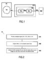
- Fig. 1 schematically shows a first example correlation engine CE-1.
- the correlation engine CE-1 is coupled to a telecommunications network NT comprising a section Sm supplying an "event notification" or alarm Am.
- the correlation engine CE-1 comprises a block Bn receiving on input the alarm Am.
- the block Bn comprises a Root Cause Analysis (RCA) module RCn and a Service Impact Analysis (SIA) module SAn.
- RCA Root Cause Analysis
- SIA Service Impact Analysis
- m is a section index from 1 to M and n is a block index from 1 to N. It may be noted that m may equal n in some cases.
- the module RCn supplies a root cause analysis result (or "root result”) RRn to its corresponding module SAn, and the module SAn supplies a service impact analysis result (or "service result”) SRn.
- the root result RRn is used to describe the physical component to be repaired in relation with the Trouble Ticket, so that it may be fixed as quickly as possible, while the service result SRn relates to the status of a service, such as Degraded or Unavailable.
- the service result SRn may be supplied to a man-machine interface MMI (such as a Graphical Interface/Topology Viewer) or another tool used to manage Service Level Agreements SLAs, which are the contracts used to define the Quality of Service between a network operator and a client, for example requiring full availability of the service 99% of the time.
- MMI such as a Graphical Interface/Topology Viewer
- SLAs Service Level Agreements
- the service result can be used to notify a client what services are affected, to what extent (Degraded, Unavailable, etc), and the status of the repair.
- the module SAn is able to exploit the results of the module RCn, since the advantages of root cause analysis (efficient alarm grouping, trouble ticket management, problem alarm generation, and root cause analysis) correspond to the disadvantages of service impact analysis (poor alarm grouping and generation, poor Trouble Ticket management and root cause analysis), and the disadvantages of root cause analysis (poor service impact analysis and topology enrichment) correspond to the advantages of service impact analysis (good service impact analysis and topology enrichment).
- Fig. 2 is a flow chart showing an example method of implementing a correlation engine according to the first example shown in Fig. 1 .
- a correlation engine CE-1 is provided in a step S01.
- a block Bn of the correlation engine is coupled to a network section Sm.
- the RCA module RCn and the SIA module SAn of the block are configured so as to analyse an alarm Am received from the network section.
- Fig. 3 schematically shows a second example correlation engine CE-2.
- the correlation engine CE-2 corresponds to the correlation engine CE-1 described in relation with Fig. 1 , with the following additions:
- the service impact analysis module SAn further:
- the root cause analysis module RCn further:
- Fig. 4 schematically shows a third example correlation engine CE-3.
- the correlation engine CE-3 is coupled to a network NT comprising a total M equals three sections Sm (S1, S2, S3). Each section Sn supplies an alarm Am (A1, A2, A3).
- the correlation engine CE-3 comprises a stack SK of three blocks Bn (B1, B2, B3), each comprising an RCA module RCn (RC1, RC2, RC3) and a SIA module SAn (SA1, SA2, SA3) respectively.
- the index numbers n are increasing 1 to 3, and in the second direction D2 the index numbers n are decreasing 3 to 1.
- the blocks when configuring the correlation engine, are configured and arranged such that the increasing indices correspond to blocks less to more logically defined, and the decreasing indices correspond to blocks less to more physically defined. That is to say, the lower index numbers n of the stack SK of blocks allow a more detailed analysis of the problem itself, whereas the higher index numbers of the stack SK allow a more global view of the effects.
- one block for example block B2
- Blocks B1 and B3 are thus configured and coupled to block B2.
- the module RC1 receives the alarm A1 and the root result RR2 from the module RC2 of block B2, and supplies the root result RR1 to its corresponding module SA1.
- the module SA1 receives the root result RR1, supplies the service result SR1 to the module SA2 of block B2 and to the interface MMI.
- the module RC2 receives the alarm A2 and the root result RR3 from the module RC3 of block B3, and supplies the root result RR2 to the module RC1 of block B1 and to its corresponding module SA2.
- the module SA2 receives the root result RR2 and the service result SA1 from the module SA1 of block B1, and supplies a service result SR2 to the module SA3 of block B3 and to the interface MMI.
- the module RC3 receives the alarm A3, and supplies the root result RR3 to the module RC2 of block B2 and to its corresponding module SA3.
- the module SA3 receives the root result RR3 and the service result SR2 from the module SA2 of block B2, and supplies the service result SR3 to the interface MMI.
- blocks B1 and B3 are both "end blocks" of the stack SK, coupled to another block on only one side.
- Block B1 is both the first block in the first direction D1 and the last block in the second direction D2
- block B3 is both the last block in the first direction D1 and the first block in the second direction D2.
- Block B2 is an "intermediary block" of the stack SK, coupled on both sides to other blocks.
- the root cause analysis results RRn from one logical level ⁇ n ⁇ are provided to an analysis block of a lower logical level ⁇ n-1 ⁇ , to aid it in determining the root cause of an event.
- the causes of an event are grouped to determine the cause of an issue, that is to say, the physical component that has malfunctioned.
- the service impact analysis results SAn from one logical level ⁇ n ⁇ are provided to an analysis block of a higher logical level ⁇ n ⁇ , to aid it in determining the service impact of an event, which may either be due to a lower logical level, or the root cause result of the same block.
- first direction D1 and second direction D2 may be reversed, with the direction of the flow of results RRn, SAn also reversed correspondingly, such that the blocks at the bottom of the stack are more logically defined.
- the correlation engine CE-3 thus provides a flexible solution to dividing the complexity of the network into multiple sections (for example domains or layers), depending on the technology implemented, the vendors, etc. Further, each section Sm is associated with at least one block Bn providing both root cause analysis and service impact analysis. Each block Bn is thus configured for a limited set of correlation rules, simplifying its implementation, as the RCA module and the SIA module of each block Bn are adapted to the section Sm to which the block is coupled. Blocks Bn may be added, modified, and removed as needed, so that the entire network NT is managed.
- the correlation engine CE-3 is thus relatively simple to implement; since each block is independent of the others, the implementation of the root cause analysis and service impact analysis for a section is also independent, unaffected by correlation challenges of the other sections. To support new sections, a developer need simply insert one or more blocks into the correlation engine, and reconfigure the result routing accordingly.
- Adding blocks at the bottom of the stack SK (in the second direction D2) provides more accurate results of the fault. Adding blocks at the top of the stack SK (in the first direction D1) provides a more accurate view of the impacted services.
- a correlation engine may comprise a stack of blocks according to that described in relation with Fig. 1 , wherein the results (root cause analysis and service impact analysis) are not shared between blocks.
- Fig. 5 is a flow chart showing further steps of a method P2 of implementing a correlation engine according to the examples shown in Fig. 3 or 4 .
- a correlation engine CE-1, CE-2, CE-3
- a block Bn of the correlation engine is coupled to a network section Sm.
- the RCA module RCn and the SIA module SAn of the block are configured so as to analyse an alarm Am received from the network section.
- a step S10 an alarm Am supplied by the network section Sm is received on input of the root cause analysis module RCn of the block Bn.
- the RCA module RCn supplies a root result RRn.
- the SIA module SAn of the block receives the root result RRn.
- the SIA module supplies a service result SRn.
- a step S04 at least one further block Bn is provided, coupled to a network section, and configured.
- the blocks are configured such that at least one of the root result RRn or service result (SRn) supplied by one block is provided on input to another block.
- the method comprises steps S01 to S05, steps S10 to S13, and a step S14, wherein at least one RCA module RCn or SIA module SAn receives a result RRn, SRn, supplied by a module of another block.
- Fig. 6 schematically shows a fourth example correlation engine CE-4, grouping together various alternatives. It should be noted here that the provision of the following alternatives are all independent of each other, and are merely described together for the sake of convenience.
- the correlation engine CE-4 is coupled to a network NT comprising a total M equals four sections Sm (S1, S2, S3, S4), each supplying at least one alarm Am (A1, A1', A2, A3, A4).
- the correlation engine CE-4 comprises a stack SK of four blocks Bn (B1, B2, B3, B4).
- Block B1 comprises one module RC1, and two modules SA1, SA1'.
- the module RC1 receives alarms A1, A1' on input, and supplies a root result RR1 on output to modules SA1, SA1' respectively.
- Each module SA1, SA1' supplies service results SR1, SR1' on output to block B2 and to the interface MMI.
- Block B2 comprises one module RC2 and one module SA2.
- the module RC2 receives the alarms A2 and root results RR3, RR4 on input, and supplies root results RR2 on output to module RC1 and to module SA2.
- Module SA2 further receives the service results SR1, SR1' on input, and supplies the service result SR2 on output to blocks B3, B4 and to the interface MMI.
- Block B3 comprises one module RC3, and one module SA3.
- the module RC3 receives alarms A3, A4 on input, and supplies root result RR3 on output to module RC2 and to module SA3.
- Module SA3 further receives the service result SR2 on input, and supplies the service result SR3 on output to block B4 and to the interface MMI.
- Block B4 comprises two modules RC4, RC4', and one module SA4.
- the module RC4' receives alarm A4 on input, and supplies root result RR4' on output to module RC4 and to module SA4.
- the module RC4 receives alarm A4 on input, and supplies root result RR4 on output to module RC2 and to module SA4.
- Module SA4 further receives the service results SR2, SR3 on input, and supplies the service result SR4 on output to the interface MMI.
- the correlation engine its coupling to sections and to the interface MMI, and the contents and coupling of the blocks are configurable as needed.
- the interface MMI is typically a management software, comprising a topographical viewer of the network, showing status of elements, alarms, interconnections, and so forth. It allows a network operator to get an overview of the network, spot problems, track trouble tickets, and the like. It may nevertheless be a simple display, print-out, and in general any other means of conveying information about the event notification and its cause and effect.
- Fig. 7 schematically shows a computer CP comprising a computer program P1 supplied on a medium MD1 readable by the computer.
- the computer CP further comprises a man-machine interface MMI and a processor PR configured to execute the program P1.
- the program P1 comprises instructions Inst. for carrying out the steps S01 to S03 of the method described in relation with Fig. 2 .
- the program is preferably stored in a non-transitory manner on the medium MD1.
- Fig. 8 schematically shows a computer CP comprising a computer program P2 supplied on a medium MD2 readable by the computer.
- the computer CP further comprises a man-machine interface MMI and a processor PR configured to execute the program P2.
- the program P2 comprises instructions Inst. for carrying out the steps S01 to S14 of the method described in relation with Fig. 5 .
- the program is preferably stored in a non-transitory manner on the medium MD2.
- alarm should be interpreted broadly as an event notification of an event pertaining to the element, and not necessarily one having a negative impact. It may also merely be related to a state of the element.
- network section should be interpreted broadly as domain, infrastructure, layer, element, etc.
Landscapes
- Engineering & Computer Science (AREA)
- Computer Networks & Wireless Communication (AREA)
- Signal Processing (AREA)
- Human Computer Interaction (AREA)
- Data Exchanges In Wide-Area Networks (AREA)
Abstract
Description
- A telecommunication network is generally comprised of a large number, sometimes millions, of network elements. These network elements are provided by different vendors, each specialized in different domains and layers, such that the entire network is quite heterogeneous. The network elements are usually self-monitored, so as to detect a failure and notify the failure by means of fault information.
- A network operator or provider is responsible for an infrastructure comprising many network elements. It is therefore helpful for the provider, monitoring the infrastructure, to be able to rapidly identify the root cause of a failure and the affected services so that they may be repaired in order to ensure a high quality of service and to meet service contracts.
-
-
Fig. 1 schematically shows a first example correlation engine; -
Fig. 2 is a flow chart showing an example method of implementing a correlation engine; -
Fig. 3 schematically shows a second example correlation engine; -
Fig. 4 schematically shows a third example correlation engine; -
Fig. 5 is a flow chart showing further steps of an example method of implementing a correlation engine; -
Fig. 6 schematically shows a fourth example correlation engine; -
Fig. 7 schematically shows a computer comprising an example computer program; and -
Fig. 8 schematically shows a computer comprising an example computer program. - Since network elements are generally interconnected, a failure of one element affects the others; as each element is self-monitored, a flood of information may result.
- Root cause analysis is thus employed to determine the network element that caused the failure as opposed to the network element(s) merely reacting to the failure. A "Trouble Ticket" is then issued so that the failure may be fixed, either automatically or by a human technician. The Trouble Ticket should thus identify the failure as accurately as possible, to save time and resources. On the contrary, service impact analysis is used to determine the impact of such a failure, either on the physical components themselves or on logical services, generally in order to understand the impact on a service contract.
- A correlation engine may be used to provide root cause or service impact analysis. A correlation engine is thus coupled to a domain on input, and generally supplies Trouble Tickets or status indicators on output. These correlation engines have varying complexities and efficiencies, and may be hard to adapt to an evolving network.
-
Fig. 1 schematically shows a first example correlation engine CE-1. The correlation engine CE-1 is coupled to a telecommunications network NT comprising a section Sm supplying an "event notification" or alarm Am. The correlation engine CE-1 comprises a block Bn receiving on input the alarm Am. The block Bn comprises a Root Cause Analysis (RCA) module RCn and a Service Impact Analysis (SIA) module SAn. In this example, m is a section index from 1 to M and n is a block index from 1 to N. It may be noted that m may equal n in some cases. - According to this example, the module RCn supplies a root cause analysis result (or "root result") RRn to its corresponding module SAn, and the module SAn supplies a service impact analysis result (or "service result") SRn. The root result RRn is used to describe the physical component to be repaired in relation with the Trouble Ticket, so that it may be fixed as quickly as possible, while the service result SRn relates to the status of a service, such as Degraded or Unavailable. The service result SRn may be supplied to a man-machine interface MMI (such as a Graphical Interface/Topology Viewer) or another tool used to manage Service Level Agreements SLAs, which are the contracts used to define the Quality of Service between a network operator and a client, for example requiring full availability of the service 99% of the time. The service result can be used to notify a client what services are affected, to what extent (Degraded, Unavailable, etc), and the status of the repair.
- In this manner, the module SAn is able to exploit the results of the module RCn, since the advantages of root cause analysis (efficient alarm grouping, trouble ticket management, problem alarm generation, and root cause analysis) correspond to the disadvantages of service impact analysis (poor alarm grouping and generation, poor Trouble Ticket management and root cause analysis), and the disadvantages of root cause analysis (poor service impact analysis and topology enrichment) correspond to the advantages of service impact analysis (good service impact analysis and topology enrichment).
-
Fig. 2 is a flow chart showing an example method of implementing a correlation engine according to the first example shown inFig. 1 . In a step S01, a correlation engine CE-1 is provided. In a step S02, a block Bn of the correlation engine is coupled to a network section Sm. In a step S03, the RCA module RCn and the SIA module SAn of the block are configured so as to analyse an alarm Am received from the network section. -
Fig. 3 schematically shows a second example correlation engine CE-2. The correlation engine CE-2 corresponds to the correlation engine CE-1 described in relation withFig. 1 , with the following additions: - The service impact analysis module SAn further:
- supplies on output the service result SRn to a module SA{n+1} belonging to a block B{n+1} arranged in a first direction D1; and
- receives on input a service result SR{n-1} from a module SA{n-1} belonging to a block B{n-1} arranged in a second direction D2, opposite the first direction D1.
- The root cause analysis module RCn further:
- supplies on output the root result RRn to a module RC{n-1} belonging to a block B{n-1} arranged in the second direction D2; and
- receives on input a root result RR{n+1} from a module RC{n+1} belonging to a block B{n+1} arranged in the first direction D1.
- It is to be noted that the results have been here described as being received from/provided to the nearest neighbor {n±1}, but as will be seen in relation with
Fig. 4 , they may be instead or additionally provided to further neighbors. Thus, it may be generalized as {n±x}, wherein x is an integer greater than or equal to 1. - The capability to provide and receive the root cause and service impact results from other blocks will now be described in further detail with respect to
Fig. 4 . -
Fig. 4 schematically shows a third example correlation engine CE-3. In this example, the correlation engine CE-3 is coupled to a network NT comprising a total M equals three sections Sm (S1, S2, S3). Each section Sn supplies an alarm Am (A1, A2, A3). - The correlation engine CE-3 comprises a stack SK of three blocks Bn (B1, B2, B3), each comprising an RCA module RCn (RC1, RC2, RC3) and a SIA module SAn (SA1, SA2, SA3) respectively.
- It may be noted that in the first direction D1 the index numbers n are increasing 1 to 3, and in the second direction D2 the index numbers n are decreasing 3 to 1.
- According to one embodiment, when configuring the correlation engine, the blocks are configured and arranged such that the increasing indices correspond to blocks less to more logically defined, and the decreasing indices correspond to blocks less to more physically defined. That is to say, the lower index numbers n of the stack SK of blocks allow a more detailed analysis of the problem itself, whereas the higher index numbers of the stack SK allow a more global view of the effects.
- In this example, one block, for example block B2, was already configured as shown in relation with
Fig. 2 , when it was desired to add two blocks to support new sections, one block (B3) of a higher logical level, and one block (B1) of a lower logical level. Blocks B1 and B3 are thus configured and coupled to block B2. - The module RC1 receives the alarm A1 and the root result RR2 from the module RC2 of block B2, and supplies the root result RR1 to its corresponding module SA1. The module SA1 receives the root result RR1, supplies the service result SR1 to the module SA2 of block B2 and to the interface MMI.
- The module RC2 receives the alarm A2 and the root result RR3 from the module RC3 of block B3, and supplies the root result RR2 to the module RC1 of block B1 and to its corresponding module SA2. The module SA2 receives the root result RR2 and the service result SA1 from the module SA1 of block B1, and supplies a service result SR2 to the module SA3 of block B3 and to the interface MMI.
- The module RC3 receives the alarm A3, and supplies the root result RR3 to the module RC2 of block B2 and to its corresponding module SA3. The module SA3 receives the root result RR3 and the service result SR2 from the module SA2 of block B2, and supplies the service result SR3 to the interface MMI.
- In this example, blocks B1 and B3 are both "end blocks" of the stack SK, coupled to another block on only one side. Block B1 is both the first block in the first direction D1 and the last block in the second direction D2, and block B3 is both the last block in the first direction D1 and the first block in the second direction D2. Block B2 is an "intermediary block" of the stack SK, coupled on both sides to other blocks.
- The root cause analysis results RRn from one logical level {n} are provided to an analysis block of a lower logical level {n-1}, to aid it in determining the root cause of an event. In this manner, the causes of an event are grouped to determine the cause of an issue, that is to say, the physical component that has malfunctioned. The service impact analysis results SAn from one logical level {n} are provided to an analysis block of a higher logical level {n}, to aid it in determining the service impact of an event, which may either be due to a lower logical level, or the root cause result of the same block.
- It is to be understood that the first direction D1 and second direction D2 may be reversed, with the direction of the flow of results RRn, SAn also reversed correspondingly, such that the blocks at the bottom of the stack are more logically defined.
- The correlation engine CE-3 thus provides a flexible solution to dividing the complexity of the network into multiple sections (for example domains or layers), depending on the technology implemented, the vendors, etc. Further, each section Sm is associated with at least one block Bn providing both root cause analysis and service impact analysis. Each block Bn is thus configured for a limited set of correlation rules, simplifying its implementation, as the RCA module and the SIA module of each block Bn are adapted to the section Sm to which the block is coupled. Blocks Bn may be added, modified, and removed as needed, so that the entire network NT is managed.
- The correlation engine CE-3 is thus relatively simple to implement; since each block is independent of the others, the implementation of the root cause analysis and service impact analysis for a section is also independent, unaffected by correlation challenges of the other sections. To support new sections, a developer need simply insert one or more blocks into the correlation engine, and reconfigure the result routing accordingly.
- Adding blocks at the bottom of the stack SK (in the second direction D2) provides more accurate results of the fault. Adding blocks at the top of the stack SK (in the first direction D1) provides a more accurate view of the impacted services.
- It may nevertheless be noted that according to one embodiment, a correlation engine may comprise a stack of blocks according to that described in relation with
Fig. 1 , wherein the results (root cause analysis and service impact analysis) are not shared between blocks. -
Fig. 5 is a flow chart showing further steps of a method P2 of implementing a correlation engine according to the examples shown inFig. 3 or 4 . In a step S01, a correlation engine (CE-1, CE-2, CE-3) is provided. In a step S02, a block Bn of the correlation engine is coupled to a network section Sm. In a step S03, the RCA module RCn and the SIA module SAn of the block are configured so as to analyse an alarm Am received from the network section. - According to one option, in a step S10, an alarm Am supplied by the network section Sm is received on input of the root cause analysis module RCn of the block Bn. In a step S11, the RCA module RCn supplies a root result RRn. In a step S12, the SIA module SAn of the block receives the root result RRn. In a step S13, the SIA module supplies a service result SRn.
- According to one option, in a step S04, at least one further block Bn is provided, coupled to a network section, and configured. In a step S05, the blocks are configured such that at least one of the root result RRn or service result (SRn) supplied by one block is provided on input to another block.
- According to another option, the method comprises steps S01 to S05, steps S10 to S13, and a step S14, wherein at least one RCA module RCn or SIA module SAn receives a result RRn, SRn, supplied by a module of another block.
-
Fig. 6 schematically shows a fourth example correlation engine CE-4, grouping together various alternatives. It should be noted here that the provision of the following alternatives are all independent of each other, and are merely described together for the sake of convenience. - In this example, the correlation engine CE-4 is coupled to a network NT comprising a total M equals four sections Sm (S1, S2, S3, S4), each supplying at least one alarm Am (A1, A1', A2, A3, A4). The correlation engine CE-4 comprises a stack SK of four blocks Bn (B1, B2, B3, B4).
- Block B1 comprises one module RC1, and two modules SA1, SA1'. The module RC1 receives alarms A1, A1' on input, and supplies a root result RR1 on output to modules SA1, SA1' respectively. Each module SA1, SA1' supplies service results SR1, SR1' on output to block B2 and to the interface MMI.
- Block B2 comprises one module RC2 and one module SA2. The module RC2 receives the alarms A2 and root results RR3, RR4 on input, and supplies root results RR2 on output to module RC1 and to module SA2. Module SA2 further receives the service results SR1, SR1' on input, and supplies the service result SR2 on output to blocks B3, B4 and to the interface MMI.
- Block B3 comprises one module RC3, and one module SA3. The module RC3 receives alarms A3, A4 on input, and supplies root result RR3 on output to module RC2 and to module SA3. Module SA3 further receives the service result SR2 on input, and supplies the service result SR3 on output to block B4 and to the interface MMI.
- Block B4 comprises two modules RC4, RC4', and one module SA4. The module RC4' receives alarm A4 on input, and supplies root result RR4' on output to module RC4 and to module SA4. The module RC4 receives alarm A4 on input, and supplies root result RR4 on output to module RC2 and to module SA4. Module SA4 further receives the service results SR2, SR3 on input, and supplies the service result SR4 on output to the interface MMI.
- Thus, according to different embodiments:
- a block comprises more than one RCE module and/or SIA module;
- a root cause analysis result RRn and/or a service impact analysis result SRn is provided to more than one other block;
- an RCA module and/or a SIA module to receive on input results from a plurality of other blocks;
- a root cause analysis result RRn and/or a service impact analysis result SRn of a block Bn is not provided to/received from the nearest neighbour block {n+1} or {n-1}, but rather to/from a more distant block;
- an RCA module receives alarms from a plurality of sections; and
- an RCA module receives a plurality of alarms from a section.
- In general, the correlation engine, its coupling to sections and to the interface MMI, and the contents and coupling of the blocks are configurable as needed.
- The interface MMI is typically a management software, comprising a topographical viewer of the network, showing status of elements, alarms, interconnections, and so forth. It allows a network operator to get an overview of the network, spot problems, track trouble tickets, and the like. It may nevertheless be a simple display, print-out, and in general any other means of conveying information about the event notification and its cause and effect.
-
Fig. 7 schematically shows a computer CP comprising a computer program P1 supplied on a medium MD1 readable by the computer. The computer CP further comprises a man-machine interface MMI and a processor PR configured to execute the program P1. The program P1 comprises instructions Inst. for carrying out the steps S01 to S03 of the method described in relation withFig. 2 . The program is preferably stored in a non-transitory manner on the medium MD1. -
Fig. 8 schematically shows a computer CP comprising a computer program P2 supplied on a medium MD2 readable by the computer. The computer CP further comprises a man-machine interface MMI and a processor PR configured to execute the program P2. The program P2 comprises instructions Inst. for carrying out the steps S01 to S14 of the method described in relation withFig. 5 . The program is preferably stored in a non-transitory manner on the medium MD2. - It may be noted that while the method of
Fig. 2 was described in relation with the correlation engine CE-1 ofFig. 1 , and while the method ofFig. 5 was described in relation with the correlation engines CE-2, CE-3 ofFigs. 2 and3 , that these methods are applicable to all the correlation engine examples provided in this description. - The term "alarm" should be interpreted broadly as an event notification of an event pertaining to the element, and not necessarily one having a negative impact. It may also merely be related to a state of the element.
- Although certain examples of correlation engines have been described, it is to be understood that changes and additions may be made to the described examples within the scope of the appended claims.
- In particular, reference to "an" or "a" section, alarm, block, module, result etc. should not be taken as referring to only one item.
- The term "network section" should be interpreted broadly as domain, infrastructure, layer, element, etc.
Claims (15)
- A network correlation engine (CE-1, CE-2, CE-3, CE-4) to be coupled to a telecommunication network (NT) comprising at least one network section (Sm, S1, S2, S3, S4) to supply at least one event notification (Am, A1, A1', A2, A3, A4) upon detection of an event relating to the section, wherein the correlation engine comprises at least one event analysis block (Bn, B1, B2, B3, B4) comprising at least:- a root cause analysis module (RCn, RC1, RC2, RC3, RC4, RC4') to receive on input the event notification and to supply on output a root cause analysis result (RRn, RR1, RR2, RR3, RR4, RR4, RR4'), and- a service analysis module (SAn, SA1, SA1', SA2, SA3, SA4) to receive on input the root cause analysis result from the root cause analysis module of the block and to supply on output a service impact analysis result (SRn, SR1, SR1', SR2, SR3, SR4).
- The network correlation engine (CE-2, CE-3, CE-4) according to claim 1, wherein:- the root cause analysis module further:- receives on input a root cause analysis result (RR{n+x}, RR{n+1}, RR2, RR3, RR4) from a root cause analysis module (RR{n+x}, RC{n+1}, RC2, RC3, RC4) of an event analysis block (B2, B3, B4) arranged in a first direction (D1), and- supplies on output its root cause analysis result (RR2, RR3, RR4) to a root cause analysis module (RC{n-x}, RC{n-1}, RC1, RC2, RC3) of an event analysis block (B1, B2, B3) arranged in a second direction (D2), opposite to the first, and- the service analysis module further:- receives on input a service impact analysis result (SR{n-x}, SR{n-1}, SR1, SR1', SR2, SR3) from a service impact module (SA{n-x}, SA{n-1}, SA1, SA1', SA2, SA3) of an event analysis block (B1, B2, B3) arranged in the second direction (D2), and- supplies on output its service impact analysis result (SR1, SR1', SR2, SR3) to a service impact analysis module (SA{n+x}, SA{n+1}, SA2, SA3, SA4) of an event analysis block (B2, B3, B4) arranged in the first direction (D1).
- The network correlation engine (CE-3, CE-4) according to claim 2, comprising a stack (SK) of at least two event analysis blocks (Bn, B1, B2, B3, B4), each block being coupled on input to the telecommunication network (NT) and receiving an event notification (Am, A1, A1', A2, A3, A4) of an event of the network.
- The network correlation engine (CE-3, CE-4) according to claim 3, wherein the first direction (D1) corresponds to increasingly logically defined blocks, and the second direction (D2) corresponds to increasingly physically defined blocks.
- The network correlation engine (CE-4) according to claim 3, wherein a root cause analysis result or service impact analysis result is supplied to more than one other block.
- The network correlation engine (CE-4) according to claim 3, wherein a block (B3) receives event notifications (A3, A4) from more than one network section (S3, S4).
- The network correlation engine (CE-4) according to claim 3, wherein a block (B1) receives more than one event notifications (A1, A1') from a network section (S1).
- The network correlation engine (CE-4) according to claim 3, wherein a block comprises more than one root cause analysis module (RC4, RC4') and/or service analysis module (SA1, SA1').
- The network correlation engine (CE-1, CE-2, CE-3, CE-4) according to claim 1, wherein the service impact analysis result (SRn, SR1, SR1', SR2, SR3, SR4) is supplied to a man-machine interface (MMI).
- The network correlation engine (CE-1, CE-2, CE-3, CE-4) according to claim 9, wherein the man-machine interface (MMI) is a graphical display used to monitor the status of the network and of the correlation engine.
- A method (P1, P2) comprising:- providing (S01) a correlation engine (CE-1, CE-2, CE-3, CE-4) comprising at least one event analysis block (Bn, B1, B2, B3, B4) comprising at least:- a root cause analysis module (RCn, RC1, RC2, RC3, RC4, RC4') to receive on input the event notification and to supply on output a root cause analysis result (RRn, RR1, RR2, RR3, RR4, RR4, RR4'), and- a service analysis module (SAn, SA1, SA1', SA2, SA3, SA4) to receive on input the root cause analysis result from the root cause analysis module of the block and to supply on output a service impact analysis result (SRn, SR1, SR1', SR2, SR3, SR4);- coupling (S02) the block to a network section (Sm, S1, S2, S3, S4) of a telecommunications network (NT) to supply at least one event notification (Am, A1, A1', A2, A3, A4) upon detection of an event relating to the section; and- configuring (S03) the root cause analysis module (RCn, RC1, RC2, RC3, RC4, RC4') and the service impact analysis module (SAn, SA1, SA1', SA2, SA3, SA4) of the block so as to analyse an event notification received from the network section, provide a root cause analysis result (RRn) and a service impact analysis result (SRn).
- The method according to claim 11, further comprising:- receiving (S10) an alarm (Am) on input to the root cause analysis module (RCn) of a block (Bn);- supplying (S11), by the root cause analysis module (RCn), a root result (RRn);- receiving (S12), by the service impact analysis module (SAn) of the block, the root result (RRn); and- supplying (S13), by the service impact analysis module (SAn), a service impact analysis result (SRn).
- The method according to claim 11, further comprising:- providing (S04) at least one further event analysis block (Bn), and- configuring (S05) the blocks such that at least one of the root cause analysis result (RRn) and/or service impact analysis result (SRn) supplied by one block is provided on input to another block.
- The method according to claim 13, further comprising:- receiving (S10) an alarm (Am) on input to the root cause analysis module (RCn) of a block (Bn);- supplying (S11), by the root cause analysis module (RCn), a root result (RRn);- receiving (S12), by the service impact analysis module (SAn) of the block, the root result (RRn);- supplying (S13), by the service impact analysis module (SAn), a service impact analysis result (SRn); and- receiving (S14), by at least one root cause analysis module (RCn) or service impact analysis module (SAn), a root cause analysis result (RRn) or service impact analysis result (SRn) supplied by another block.
- A computer program (P1, P2) comprising instructions (Inst) for the execution of a method when the program is implemented by a computer (CP), the instructions comprising:- providing (S01) a correlation engine (CE-1, CE-2, CE-3, CE-4) comprising at least one event analysis block (Bn, B1, B2, B3, B4) comprising at least:- a root cause analysis module (RCn, RC1, RC2, RC3, RC4, RC4') to receive on input the event notification and to supply on output a root cause analysis result (RRn, RR1, RR2, RR3, RR4, RR4, RR4'), and- a service analysis module (SAn, SA1, SA1', SA2, SA3, SA4) to receive on input the root cause analysis result from the root cause analysis module of the block and to supply on output a service impact analysis result (SRn, SR1, SR1', SR2, SR3, SR4);- coupling (S02) the block to a network section (Sm, S1, S2, S3, S4) of a telecommunications network (NT) to supply at least one event notification (Am, A1, A1', A2, A3, A4) upon detection of an event relating to the section; and- configuring (S03) the root cause analysis module (RCn, RC1, RC2, RC3, RC4, RC4') and the service impact analysis module (SAn, SA1, SA1', SA2, SA3, SA4) of the block so as to analyse an event notification received from the network section, provide a root cause analysis result (RRn) and a service impact analysis result (SRn).
Priority Applications (3)
| Application Number | Priority Date | Filing Date | Title |
|---|---|---|---|
| EP14306276.8A EP2985949B1 (en) | 2014-08-14 | 2014-08-14 | Correlation engine comprising root cause and service impact analyses |
| US15/329,784 US10693710B2 (en) | 2014-08-14 | 2015-02-06 | Correlation engine comprising root cause and service impact analyses |
| PCT/US2015/014724 WO2016025024A1 (en) | 2014-08-14 | 2015-02-06 | Correlation engine comprising root cause and service impact analyses |
Applications Claiming Priority (1)
| Application Number | Priority Date | Filing Date | Title |
|---|---|---|---|
| EP14306276.8A EP2985949B1 (en) | 2014-08-14 | 2014-08-14 | Correlation engine comprising root cause and service impact analyses |
Publications (2)
| Publication Number | Publication Date |
|---|---|
| EP2985949A1 true EP2985949A1 (en) | 2016-02-17 |
| EP2985949B1 EP2985949B1 (en) | 2018-05-23 |
Family
ID=51453709
Family Applications (1)
| Application Number | Title | Priority Date | Filing Date |
|---|---|---|---|
| EP14306276.8A Active EP2985949B1 (en) | 2014-08-14 | 2014-08-14 | Correlation engine comprising root cause and service impact analyses |
Country Status (3)
| Country | Link |
|---|---|
| US (1) | US10693710B2 (en) |
| EP (1) | EP2985949B1 (en) |
| WO (1) | WO2016025024A1 (en) |
Families Citing this family (2)
| Publication number | Priority date | Publication date | Assignee | Title |
|---|---|---|---|---|
| US11716276B2 (en) * | 2020-03-06 | 2023-08-01 | Juniper Networks, Inc. | Detecting miswirings in a spine and leaf topology of network devices |
| CN118202632A (en) * | 2021-11-11 | 2024-06-14 | 华为技术有限公司 | A method and device for sending fault warning information |
Citations (6)
| Publication number | Priority date | Publication date | Assignee | Title |
|---|---|---|---|---|
| US5768501A (en) * | 1996-05-28 | 1998-06-16 | Cabletron Systems | Method and apparatus for inter-domain alarm correlation |
| WO2000074314A2 (en) * | 1999-06-02 | 2000-12-07 | Accenture Llp | A system and method for problem management in a hybrid network architecture |
| WO2002006971A1 (en) * | 2000-07-13 | 2002-01-24 | Aprisma Management Technologies, Inc. | Method and apparatus for a comprehensive network management system |
| EP1460801A1 (en) * | 2003-03-17 | 2004-09-22 | Tyco Telecommunications (US) Inc. | System and method for fault diagnosis using distributed alarm correlation |
| WO2012041555A1 (en) * | 2010-09-30 | 2012-04-05 | Telefonaktiebolaget L M Ericsson (Publ) | Method for determining a severity of a network incident |
| WO2012143059A1 (en) * | 2011-04-21 | 2012-10-26 | Telefonaktiebolaget L M Ericsson (Publ) | Recovery from multiple faults in a communications network |
Family Cites Families (12)
| Publication number | Priority date | Publication date | Assignee | Title |
|---|---|---|---|---|
| US5761502A (en) | 1995-12-29 | 1998-06-02 | Mci Corporation | System and method for managing a telecommunications network by associating and correlating network events |
| GB2318478B (en) * | 1996-10-21 | 2001-01-17 | Northern Telecom Ltd | Network model for alarm correlation |
| US6766368B1 (en) * | 2000-05-23 | 2004-07-20 | Verizon Laboratories Inc. | System and method for providing an internet-based correlation service |
| DE60210670D1 (en) | 2001-10-25 | 2006-05-24 | Gen Dynamics Gov Sys Corp | METHOD AND SYSTEM FOR MODELING, ANALYZING AND DISPLAYING NETWORK SECURITY EVENTS |
| US7092707B2 (en) | 2004-02-13 | 2006-08-15 | Telcordia Technologies, Inc. | Service impact analysis and alert handling in telecommunications systems |
| US7796500B1 (en) | 2004-10-26 | 2010-09-14 | Sprint Communications Company L.P. | Automated determination of service impacting events in a communications network |
| US8484336B2 (en) * | 2006-11-15 | 2013-07-09 | Cisco Technology, Inc. | Root cause analysis in a communication network |
| US8205215B2 (en) * | 2007-05-04 | 2012-06-19 | Microsoft Corporation | Automated event correlation |
| US7991872B2 (en) | 2008-05-12 | 2011-08-02 | At&T Intellectual Property Ii, L.P. | Vertical integration of network management for ethernet and the optical transport |
| US9093841B2 (en) * | 2012-02-16 | 2015-07-28 | General Electric Company | Power distribution network event correlation and analysis |
| US9059939B2 (en) * | 2012-02-23 | 2015-06-16 | Infosys Limited | End-to-end network service assurance solution |
| US9565080B2 (en) * | 2012-11-15 | 2017-02-07 | Microsoft Technology Licensing, Llc | Evaluating electronic network devices in view of cost and service level considerations |
-
2014
- 2014-08-14 EP EP14306276.8A patent/EP2985949B1/en active Active
-
2015
- 2015-02-06 WO PCT/US2015/014724 patent/WO2016025024A1/en not_active Ceased
- 2015-02-06 US US15/329,784 patent/US10693710B2/en active Active
Patent Citations (6)
| Publication number | Priority date | Publication date | Assignee | Title |
|---|---|---|---|---|
| US5768501A (en) * | 1996-05-28 | 1998-06-16 | Cabletron Systems | Method and apparatus for inter-domain alarm correlation |
| WO2000074314A2 (en) * | 1999-06-02 | 2000-12-07 | Accenture Llp | A system and method for problem management in a hybrid network architecture |
| WO2002006971A1 (en) * | 2000-07-13 | 2002-01-24 | Aprisma Management Technologies, Inc. | Method and apparatus for a comprehensive network management system |
| EP1460801A1 (en) * | 2003-03-17 | 2004-09-22 | Tyco Telecommunications (US) Inc. | System and method for fault diagnosis using distributed alarm correlation |
| WO2012041555A1 (en) * | 2010-09-30 | 2012-04-05 | Telefonaktiebolaget L M Ericsson (Publ) | Method for determining a severity of a network incident |
| WO2012143059A1 (en) * | 2011-04-21 | 2012-10-26 | Telefonaktiebolaget L M Ericsson (Publ) | Recovery from multiple faults in a communications network |
Also Published As
| Publication number | Publication date |
|---|---|
| US20170222867A1 (en) | 2017-08-03 |
| EP2985949B1 (en) | 2018-05-23 |
| US10693710B2 (en) | 2020-06-23 |
| WO2016025024A1 (en) | 2016-02-18 |
Similar Documents
| Publication | Publication Date | Title |
|---|---|---|
| US11265203B2 (en) | System and method for processing alerts indicative of conditions of a computing infrastructure | |
| ES2908461T3 (en) | Software-defined industrial network architecture for deployment in a software-defined automation system | |
| US20130145021A1 (en) | Intelligent Network Alarm Status Monitoring | |
| US6836750B2 (en) | Systems and methods for providing an automated diagnostic audit for cluster computer systems | |
| EP1437862B1 (en) | Path commissioning analysis and diagnostic tool | |
| Zhao et al. | Minimal rewiring: Efficient live expansion for clos data center networks | |
| EP3371706B1 (en) | System and method for generating a graphical display region indicative of conditions of a computing infrastructure | |
| CN113973042B (en) | Method and system for root cause analysis of network problems | |
| US10819594B2 (en) | System and method for generating a graphical display region indicative of conditions of a computing infrastructure | |
| US11316756B2 (en) | Self-tuning networks using distributed analytics | |
| US9417949B1 (en) | Generic alarm correlation by means of normalized alarm codes | |
| JP6109662B2 (en) | Operation management apparatus, operation management method, and program | |
| US20110060826A1 (en) | Detecting and determining availability of a network structure with active connection nodes | |
| EP2985949B1 (en) | Correlation engine comprising root cause and service impact analyses | |
| CN112671586B (en) | Automatic migration and guarantee method and device for service configuration | |
| CN106797322A (en) | A kind of device and method for counting availability | |
| Ok et al. | Autonomous Infrastructure & Self-Healing Clouds | |
| US11177998B2 (en) | Cross domain topology from machine learning | |
| Peci et al. | Agentic AI with Chatops for Large Scale Network Operations | |
| EP3692655B1 (en) | Locating a fault in an optical communication link | |
| Vanderlinden et al. | BladeCenter T system for the telecommunications industry | |
| CN114339493B (en) | Fault service processing method, device and storage medium based on OTN network | |
| Andrei et al. | MULTI-CLOUD MONITORING ARCHITECTURE USING NAGIOS AND SL1 | |
| Pelosi | Network management systems for overseas solutions | |
| US10965526B2 (en) | System and method for automatic transport connection of a network element |
Legal Events
| Date | Code | Title | Description |
|---|---|---|---|
| PUAI | Public reference made under article 153(3) epc to a published international application that has entered the european phase |
Free format text: ORIGINAL CODE: 0009012 |
|
| AK | Designated contracting states |
Kind code of ref document: A1 Designated state(s): AL AT BE BG CH CY CZ DE DK EE ES FI FR GB GR HR HU IE IS IT LI LT LU LV MC MK MT NL NO PL PT RO RS SE SI SK SM TR |
|
| AX | Request for extension of the european patent |
Extension state: BA ME |
|
| RAP1 | Party data changed (applicant data changed or rights of an application transferred) |
Owner name: HEWLETT PACKARD ENTERPRISE DEVELOPMENT L.P. |
|
| 17P | Request for examination filed |
Effective date: 20160805 |
|
| RBV | Designated contracting states (corrected) |
Designated state(s): AL AT BE BG CH CY CZ DE DK EE ES FI FR GB GR HR HU IE IS IT LI LT LU LV MC MK MT NL NO PL PT RO RS SE SI SK SM TR |
|
| STAA | Information on the status of an ep patent application or granted ep patent |
Free format text: STATUS: EXAMINATION IS IN PROGRESS |
|
| 17Q | First examination report despatched |
Effective date: 20170207 |
|
| GRAP | Despatch of communication of intention to grant a patent |
Free format text: ORIGINAL CODE: EPIDOSNIGR1 |
|
| STAA | Information on the status of an ep patent application or granted ep patent |
Free format text: STATUS: GRANT OF PATENT IS INTENDED |
|
| INTG | Intention to grant announced |
Effective date: 20171214 |
|
| GRAS | Grant fee paid |
Free format text: ORIGINAL CODE: EPIDOSNIGR3 |
|
| GRAA | (expected) grant |
Free format text: ORIGINAL CODE: 0009210 |
|
| STAA | Information on the status of an ep patent application or granted ep patent |
Free format text: STATUS: THE PATENT HAS BEEN GRANTED |
|
| AK | Designated contracting states |
Kind code of ref document: B1 Designated state(s): AL AT BE BG CH CY CZ DE DK EE ES FI FR GB GR HR HU IE IS IT LI LT LU LV MC MK MT NL NO PL PT RO RS SE SI SK SM TR |
|
| REG | Reference to a national code |
Ref country code: GB Ref legal event code: FG4D |
|
| REG | Reference to a national code |
Ref country code: CH Ref legal event code: EP Ref country code: CH Ref legal event code: NV Representative=s name: RENTSCH PARTNER AG, CH |
|
| REG | Reference to a national code |
Ref country code: IE Ref legal event code: FG4D |
|
| REG | Reference to a national code |
Ref country code: AT Ref legal event code: REF Ref document number: 1002403 Country of ref document: AT Kind code of ref document: T Effective date: 20180615 |
|
| REG | Reference to a national code |
Ref country code: DE Ref legal event code: R096 Ref document number: 602014025808 Country of ref document: DE |
|
| REG | Reference to a national code |
Ref country code: FR Ref legal event code: PLFP Year of fee payment: 5 |
|
| REG | Reference to a national code |
Ref country code: NL Ref legal event code: MP Effective date: 20180523 |
|
| REG | Reference to a national code |
Ref country code: LT Ref legal event code: MG4D |
|
| PG25 | Lapsed in a contracting state [announced via postgrant information from national office to epo] |
Ref country code: FI Free format text: LAPSE BECAUSE OF FAILURE TO SUBMIT A TRANSLATION OF THE DESCRIPTION OR TO PAY THE FEE WITHIN THE PRESCRIBED TIME-LIMIT Effective date: 20180523 Ref country code: BG Free format text: LAPSE BECAUSE OF FAILURE TO SUBMIT A TRANSLATION OF THE DESCRIPTION OR TO PAY THE FEE WITHIN THE PRESCRIBED TIME-LIMIT Effective date: 20180823 Ref country code: LT Free format text: LAPSE BECAUSE OF FAILURE TO SUBMIT A TRANSLATION OF THE DESCRIPTION OR TO PAY THE FEE WITHIN THE PRESCRIBED TIME-LIMIT Effective date: 20180523 Ref country code: ES Free format text: LAPSE BECAUSE OF FAILURE TO SUBMIT A TRANSLATION OF THE DESCRIPTION OR TO PAY THE FEE WITHIN THE PRESCRIBED TIME-LIMIT Effective date: 20180523 Ref country code: NO Free format text: LAPSE BECAUSE OF FAILURE TO SUBMIT A TRANSLATION OF THE DESCRIPTION OR TO PAY THE FEE WITHIN THE PRESCRIBED TIME-LIMIT Effective date: 20180823 Ref country code: SE Free format text: LAPSE BECAUSE OF FAILURE TO SUBMIT A TRANSLATION OF THE DESCRIPTION OR TO PAY THE FEE WITHIN THE PRESCRIBED TIME-LIMIT Effective date: 20180523 |
|
| PG25 | Lapsed in a contracting state [announced via postgrant information from national office to epo] |
Ref country code: LV Free format text: LAPSE BECAUSE OF FAILURE TO SUBMIT A TRANSLATION OF THE DESCRIPTION OR TO PAY THE FEE WITHIN THE PRESCRIBED TIME-LIMIT Effective date: 20180523 Ref country code: RS Free format text: LAPSE BECAUSE OF FAILURE TO SUBMIT A TRANSLATION OF THE DESCRIPTION OR TO PAY THE FEE WITHIN THE PRESCRIBED TIME-LIMIT Effective date: 20180523 Ref country code: HR Free format text: LAPSE BECAUSE OF FAILURE TO SUBMIT A TRANSLATION OF THE DESCRIPTION OR TO PAY THE FEE WITHIN THE PRESCRIBED TIME-LIMIT Effective date: 20180523 Ref country code: GR Free format text: LAPSE BECAUSE OF FAILURE TO SUBMIT A TRANSLATION OF THE DESCRIPTION OR TO PAY THE FEE WITHIN THE PRESCRIBED TIME-LIMIT Effective date: 20180824 Ref country code: NL Free format text: LAPSE BECAUSE OF FAILURE TO SUBMIT A TRANSLATION OF THE DESCRIPTION OR TO PAY THE FEE WITHIN THE PRESCRIBED TIME-LIMIT Effective date: 20180523 |
|
| REG | Reference to a national code |
Ref country code: AT Ref legal event code: MK05 Ref document number: 1002403 Country of ref document: AT Kind code of ref document: T Effective date: 20180523 |
|
| PG25 | Lapsed in a contracting state [announced via postgrant information from national office to epo] |
Ref country code: SK Free format text: LAPSE BECAUSE OF FAILURE TO SUBMIT A TRANSLATION OF THE DESCRIPTION OR TO PAY THE FEE WITHIN THE PRESCRIBED TIME-LIMIT Effective date: 20180523 Ref country code: PL Free format text: LAPSE BECAUSE OF FAILURE TO SUBMIT A TRANSLATION OF THE DESCRIPTION OR TO PAY THE FEE WITHIN THE PRESCRIBED TIME-LIMIT Effective date: 20180523 Ref country code: CZ Free format text: LAPSE BECAUSE OF FAILURE TO SUBMIT A TRANSLATION OF THE DESCRIPTION OR TO PAY THE FEE WITHIN THE PRESCRIBED TIME-LIMIT Effective date: 20180523 Ref country code: RO Free format text: LAPSE BECAUSE OF FAILURE TO SUBMIT A TRANSLATION OF THE DESCRIPTION OR TO PAY THE FEE WITHIN THE PRESCRIBED TIME-LIMIT Effective date: 20180523 Ref country code: DK Free format text: LAPSE BECAUSE OF FAILURE TO SUBMIT A TRANSLATION OF THE DESCRIPTION OR TO PAY THE FEE WITHIN THE PRESCRIBED TIME-LIMIT Effective date: 20180523 Ref country code: AT Free format text: LAPSE BECAUSE OF FAILURE TO SUBMIT A TRANSLATION OF THE DESCRIPTION OR TO PAY THE FEE WITHIN THE PRESCRIBED TIME-LIMIT Effective date: 20180523 Ref country code: EE Free format text: LAPSE BECAUSE OF FAILURE TO SUBMIT A TRANSLATION OF THE DESCRIPTION OR TO PAY THE FEE WITHIN THE PRESCRIBED TIME-LIMIT Effective date: 20180523 |
|
| REG | Reference to a national code |
Ref country code: DE Ref legal event code: R097 Ref document number: 602014025808 Country of ref document: DE |
|
| PG25 | Lapsed in a contracting state [announced via postgrant information from national office to epo] |
Ref country code: SM Free format text: LAPSE BECAUSE OF FAILURE TO SUBMIT A TRANSLATION OF THE DESCRIPTION OR TO PAY THE FEE WITHIN THE PRESCRIBED TIME-LIMIT Effective date: 20180523 Ref country code: IT Free format text: LAPSE BECAUSE OF FAILURE TO SUBMIT A TRANSLATION OF THE DESCRIPTION OR TO PAY THE FEE WITHIN THE PRESCRIBED TIME-LIMIT Effective date: 20180523 |
|
| PG25 | Lapsed in a contracting state [announced via postgrant information from national office to epo] |
Ref country code: MC Free format text: LAPSE BECAUSE OF FAILURE TO SUBMIT A TRANSLATION OF THE DESCRIPTION OR TO PAY THE FEE WITHIN THE PRESCRIBED TIME-LIMIT Effective date: 20180523 |
|
| PLBE | No opposition filed within time limit |
Free format text: ORIGINAL CODE: 0009261 |
|
| STAA | Information on the status of an ep patent application or granted ep patent |
Free format text: STATUS: NO OPPOSITION FILED WITHIN TIME LIMIT |
|
| PG25 | Lapsed in a contracting state [announced via postgrant information from national office to epo] |
Ref country code: LU Free format text: LAPSE BECAUSE OF NON-PAYMENT OF DUE FEES Effective date: 20180814 |
|
| 26N | No opposition filed |
Effective date: 20190226 |
|
| REG | Reference to a national code |
Ref country code: BE Ref legal event code: MM Effective date: 20180831 |
|
| REG | Reference to a national code |
Ref country code: IE Ref legal event code: MM4A |
|
| PG25 | Lapsed in a contracting state [announced via postgrant information from national office to epo] |
Ref country code: SI Free format text: LAPSE BECAUSE OF FAILURE TO SUBMIT A TRANSLATION OF THE DESCRIPTION OR TO PAY THE FEE WITHIN THE PRESCRIBED TIME-LIMIT Effective date: 20180523 |
|
| PG25 | Lapsed in a contracting state [announced via postgrant information from national office to epo] |
Ref country code: IE Free format text: LAPSE BECAUSE OF NON-PAYMENT OF DUE FEES Effective date: 20180814 |
|
| PG25 | Lapsed in a contracting state [announced via postgrant information from national office to epo] |
Ref country code: BE Free format text: LAPSE BECAUSE OF NON-PAYMENT OF DUE FEES Effective date: 20180831 |
|
| PG25 | Lapsed in a contracting state [announced via postgrant information from national office to epo] |
Ref country code: AL Free format text: LAPSE BECAUSE OF FAILURE TO SUBMIT A TRANSLATION OF THE DESCRIPTION OR TO PAY THE FEE WITHIN THE PRESCRIBED TIME-LIMIT Effective date: 20180523 |
|
| PG25 | Lapsed in a contracting state [announced via postgrant information from national office to epo] |
Ref country code: MT Free format text: LAPSE BECAUSE OF NON-PAYMENT OF DUE FEES Effective date: 20180814 |
|
| PG25 | Lapsed in a contracting state [announced via postgrant information from national office to epo] |
Ref country code: TR Free format text: LAPSE BECAUSE OF FAILURE TO SUBMIT A TRANSLATION OF THE DESCRIPTION OR TO PAY THE FEE WITHIN THE PRESCRIBED TIME-LIMIT Effective date: 20180523 |
|
| PG25 | Lapsed in a contracting state [announced via postgrant information from national office to epo] |
Ref country code: PT Free format text: LAPSE BECAUSE OF FAILURE TO SUBMIT A TRANSLATION OF THE DESCRIPTION OR TO PAY THE FEE WITHIN THE PRESCRIBED TIME-LIMIT Effective date: 20180523 |
|
| PG25 | Lapsed in a contracting state [announced via postgrant information from national office to epo] |
Ref country code: MK Free format text: LAPSE BECAUSE OF NON-PAYMENT OF DUE FEES Effective date: 20180523 Ref country code: HU Free format text: LAPSE BECAUSE OF FAILURE TO SUBMIT A TRANSLATION OF THE DESCRIPTION OR TO PAY THE FEE WITHIN THE PRESCRIBED TIME-LIMIT; INVALID AB INITIO Effective date: 20140814 Ref country code: CY Free format text: LAPSE BECAUSE OF FAILURE TO SUBMIT A TRANSLATION OF THE DESCRIPTION OR TO PAY THE FEE WITHIN THE PRESCRIBED TIME-LIMIT Effective date: 20180523 |
|
| PG25 | Lapsed in a contracting state [announced via postgrant information from national office to epo] |
Ref country code: IS Free format text: LAPSE BECAUSE OF FAILURE TO SUBMIT A TRANSLATION OF THE DESCRIPTION OR TO PAY THE FEE WITHIN THE PRESCRIBED TIME-LIMIT Effective date: 20180923 |
|
| REG | Reference to a national code |
Ref country code: DE Ref legal event code: R079 Ref document number: 602014025808 Country of ref document: DE Free format text: PREVIOUS MAIN CLASS: H04L0012240000 Ipc: H04L0041000000 |
|
| REG | Reference to a national code |
Ref country code: DE Ref legal event code: R081 Ref document number: 602014025808 Country of ref document: DE Owner name: HEWLETT PACKARD ENTERPRISE DEVELOPMENT LP, SPR, US Free format text: FORMER OWNER: HEWLETT PACKARD ENTERPRISE DEVELOPMENT LP, HOUSTON, TEX., US |
|
| PGFP | Annual fee paid to national office [announced via postgrant information from national office to epo] |
Ref country code: DE Payment date: 20250827 Year of fee payment: 12 |
|
| PGFP | Annual fee paid to national office [announced via postgrant information from national office to epo] |
Ref country code: GB Payment date: 20250826 Year of fee payment: 12 |
|
| PGFP | Annual fee paid to national office [announced via postgrant information from national office to epo] |
Ref country code: FR Payment date: 20250825 Year of fee payment: 12 |
|
| PGFP | Annual fee paid to national office [announced via postgrant information from national office to epo] |
Ref country code: CH Payment date: 20250901 Year of fee payment: 12 |