EP2985916A1 - Reduced memory iterative demodulation and decoding - Google Patents
Reduced memory iterative demodulation and decoding Download PDFInfo
- Publication number
- EP2985916A1 EP2985916A1 EP15179282.7A EP15179282A EP2985916A1 EP 2985916 A1 EP2985916 A1 EP 2985916A1 EP 15179282 A EP15179282 A EP 15179282A EP 2985916 A1 EP2985916 A1 EP 2985916A1
- Authority
- EP
- European Patent Office
- Prior art keywords
- data
- symbol
- instructions
- receiver
- llr
- Prior art date
- Legal status (The legal status is an assumption and is not a legal conclusion. Google has not performed a legal analysis and makes no representation as to the accuracy of the status listed.)
- Granted
Links
Images


Classifications
-
- H—ELECTRICITY
- H04—ELECTRIC COMMUNICATION TECHNIQUE
- H04L—TRANSMISSION OF DIGITAL INFORMATION, e.g. TELEGRAPHIC COMMUNICATION
- H04L1/00—Arrangements for detecting or preventing errors in the information received
- H04L1/004—Arrangements for detecting or preventing errors in the information received by using forward error control
- H04L1/0045—Arrangements at the receiver end
- H04L1/0054—Maximum-likelihood or sequential decoding, e.g. Viterbi, Fano, ZJ algorithms
-
- H—ELECTRICITY
- H03—ELECTRONIC CIRCUITRY
- H03M—CODING; DECODING; CODE CONVERSION IN GENERAL
- H03M13/00—Coding, decoding or code conversion, for error detection or error correction; Coding theory basic assumptions; Coding bounds; Error probability evaluation methods; Channel models; Simulation or testing of codes
- H03M13/29—Coding, decoding or code conversion, for error detection or error correction; Coding theory basic assumptions; Coding bounds; Error probability evaluation methods; Channel models; Simulation or testing of codes combining two or more codes or code structures, e.g. product codes, generalised product codes, concatenated codes, inner and outer codes
- H03M13/2957—Turbo codes and decoding
-
- H—ELECTRICITY
- H03—ELECTRONIC CIRCUITRY
- H03M—CODING; DECODING; CODE CONVERSION IN GENERAL
- H03M13/00—Coding, decoding or code conversion, for error detection or error correction; Coding theory basic assumptions; Coding bounds; Error probability evaluation methods; Channel models; Simulation or testing of codes
- H03M13/37—Decoding methods or techniques, not specific to the particular type of coding provided for in groups H03M13/03 - H03M13/35
- H03M13/3776—Decoding methods or techniques, not specific to the particular type of coding provided for in groups H03M13/03 - H03M13/35 using a re-encoding step during the decoding process
-
- H—ELECTRICITY
- H03—ELECTRONIC CIRCUITRY
- H03M—CODING; DECODING; CODE CONVERSION IN GENERAL
- H03M13/00—Coding, decoding or code conversion, for error detection or error correction; Coding theory basic assumptions; Coding bounds; Error probability evaluation methods; Channel models; Simulation or testing of codes
- H03M13/63—Joint error correction and other techniques
- H03M13/6325—Error control coding in combination with demodulation
-
- H—ELECTRICITY
- H03—ELECTRONIC CIRCUITRY
- H03M—CODING; DECODING; CODE CONVERSION IN GENERAL
- H03M13/00—Coding, decoding or code conversion, for error detection or error correction; Coding theory basic assumptions; Coding bounds; Error probability evaluation methods; Channel models; Simulation or testing of codes
- H03M13/65—Purpose and implementation aspects
- H03M13/6502—Reduction of hardware complexity or efficient processing
- H03M13/6505—Memory efficient implementations
-
- H—ELECTRICITY
- H03—ELECTRONIC CIRCUITRY
- H03M—CODING; DECODING; CODE CONVERSION IN GENERAL
- H03M13/00—Coding, decoding or code conversion, for error detection or error correction; Coding theory basic assumptions; Coding bounds; Error probability evaluation methods; Channel models; Simulation or testing of codes
- H03M13/65—Purpose and implementation aspects
- H03M13/6577—Representation or format of variables, register sizes or word-lengths and quantization
- H03M13/6588—Compression or short representation of variables
-
- H—ELECTRICITY
- H03—ELECTRONIC CIRCUITRY
- H03M—CODING; DECODING; CODE CONVERSION IN GENERAL
- H03M7/00—Conversion of a code where information is represented by a given sequence or number of digits to a code where the same, similar or subset of information is represented by a different sequence or number of digits
-
- H—ELECTRICITY
- H03—ELECTRONIC CIRCUITRY
- H03M—CODING; DECODING; CODE CONVERSION IN GENERAL
- H03M7/00—Conversion of a code where information is represented by a given sequence or number of digits to a code where the same, similar or subset of information is represented by a different sequence or number of digits
- H03M7/30—Compression; Expansion; Suppression of unnecessary data, e.g. redundancy reduction
- H03M7/3082—Vector coding
-
- H—ELECTRICITY
- H04—ELECTRIC COMMUNICATION TECHNIQUE
- H04L—TRANSMISSION OF DIGITAL INFORMATION, e.g. TELEGRAPHIC COMMUNICATION
- H04L1/00—Arrangements for detecting or preventing errors in the information received
- H04L1/004—Arrangements for detecting or preventing errors in the information received by using forward error control
- H04L1/0045—Arrangements at the receiver end
- H04L1/0047—Decoding adapted to other signal detection operation
- H04L1/005—Iterative decoding, including iteration between signal detection and decoding operation
-
- H—ELECTRICITY
- H04—ELECTRIC COMMUNICATION TECHNIQUE
- H04L—TRANSMISSION OF DIGITAL INFORMATION, e.g. TELEGRAPHIC COMMUNICATION
- H04L1/00—Arrangements for detecting or preventing errors in the information received
- H04L1/20—Arrangements for detecting or preventing errors in the information received using signal quality detector
- H04L1/208—Arrangements for detecting or preventing errors in the information received using signal quality detector involving signal re-encoding
-
- H—ELECTRICITY
- H04—ELECTRIC COMMUNICATION TECHNIQUE
- H04L—TRANSMISSION OF DIGITAL INFORMATION, e.g. TELEGRAPHIC COMMUNICATION
- H04L1/00—Arrangements for detecting or preventing errors in the information received
- H04L1/004—Arrangements for detecting or preventing errors in the information received by using forward error control
- H04L1/0056—Systems characterized by the type of code used
- H04L1/0071—Use of interleaving
Definitions
- Various exemplary embodiments disclosed herein relate generally to reduced memory iterative baseband processing in communication systems.
- Baseband processing for wireless receivers mostly includes demodulation, deinterleaving, and forward error correction (FEC) steps.
- FEC forward error correction
- various schemes can be introduced to improve (i . e ., decrease) the bit error rate (BER) of the received signal.
- BER bit error rate
- Many of these techniques use the knowledge of the transmitted signal characteristics (such as modulation type and pilot data) to detect as accurately as possible the channel characteristics and compensate for them.
- a receiver including: a posteriori probability demodulator configured to receive an input digital signal and output demodulated data; a deinterleaver configured to deinterleave the demodulated data; a forward error correction (FEC) decoder configured to error correct the demodulated data; a FEC encoder configured to encode the error corrected demodulated data; an interleaver configured to interleave the FEC encoded data and output the interleaved FEC encoded data to the posteriori probability demodulator; and a symbol compressor/decompressor configured to compress symbol data from the a posteriori demodulator and store the compressed data in a symbol memory and configured to decompress compressed symbol data stored in the symbol memory.
- FEC forward error correction
- Compressing the symbol data may include quantizing the symbol data.
- Compressing the symbol data may include using one of lossy compression, lossless compression, and lossless and lossy compression.
- the receiver may further comprise a log likelihood ratio (LLR) compressor/decompressor configured to compress LLR data from the interleaver and store the compressed LLR data in an interleave memory and configured to decompress compressed LLR data stored in the interleave memory.
- LLR log likelihood ratio
- Compressing the LLR data may include quantizing the LLR data.
- Compressing the symbol data may include using one of lossy compression, lossless compression, and lossless and lossy compression.
- various exemplary embodiments relate to a receiver, including: a posteriori probability demodulator configured to receive an input digital signal and output demodulated data; a deinterleaver configured to deinterleave the demodulated data; a soft input soft output (SISO) decoder configured to decode the demodulated data; an interleaver configured to interleave the demodulated data and output the interleaved demodulated data to the posteriori probability demodulator; and a symbol compressor/decompressor configured to compress symbol data from the a posteriori demodulator and store the compressed data in a symbol memory and configured to decompress compressed symbol data stored in the symbol memory.
- a posteriori probability demodulator configured to receive an input digital signal and output demodulated data
- a deinterleaver configured to deinterleave the demodulated data
- a soft input soft output (SISO) decoder configured to decode the demodulated data
- an interleaver configured to interleave the demodulated data and output the inter
- Compressing the symbol data may include quantizing the symbol data.
- Compressing the symbol data may include using one of lossy compression, lossless compression, and lossless and lossy compression.
- the receiver may further comprise a log likelihood ratio (LLR) compressor/decompressor configured to compress LLR data from the interleaver and store the compressed LLR data in an interleave memory and configured to decompress compressed LLR data stored in the interleave memory.
- LLR log likelihood ratio
- Compressing the LLR data may include quantizing the LLR data.
- Compressing the symbol data may include using one of lossy compression, lossless compression, and lossless and lossy compression.
- various exemplary embodiments relate to a non-transitory machine-readable storage medium encoded with instructions for execution by a processor in a receiver, including: instructions for a posteriori probability demodulating an input digital signal and outputting demodulated data; instructions for deinterleaving the demodulated data; instructions for a forward error correction (FEC) decoding the demodulated data; instructions for FEC encoding the error corrected demodulated data; instructions for interleaving the FEC encoded data; instructions for compressing symbol data from the demodulated data and storing the compressed data in a symbol memory; and instructions for decompressing compressed symbol data stored in the symbol memory.
- FEC forward error correction
- Compressing the symbol data includes quantizing the symbol data.
- the non-transitory machine-readable storage medium may further comprise: instructions for compressing interleaved data and storing the compressed interleaved data in an interleave memory; and instructions for decompressing compressed interleaved data stored in the interleave memory. Compressing the interleaved data may include quantizing the interleaved data.
- various exemplary embodiments relate to a non-transitory machine-readable storage medium encoded with instructions for execution by a processor in a receiver, including: instructions for a posteriori probability demodulating an input digital signal and outputting demodulated data; instructions for deinterleaving the demodulated data; instructions for soft input soft output (SISO) decoding the demodulated data; instructions for interleaving the SISO encoded data; instructions for compressing symbol data from the demodulated data and storing the compressed data in a symbol memory; and instructions for decompressing compressed symbol data stored in the symbol memory.
- SISO soft input soft output
- Compressing the symbol data may include quantizing the symbol data.
- FIG. 1 illustrates a block diagram of a typical digital transmission baseband system.
- the digital transmission baseband system includes a forward error correction (FEC) encoder 110, an interleaver 120, a modulator 130, and a transmission (TX) filter and digital to analog converter (DAC) 140.
- FEC forward error correction
- TX transmission filter and digital to analog converter
- the encoded bits are interleaved by the interleaver 120 resulting in a reordering of the sequence x k ⁇ x k' .
- the bits may be modulated by the modulator 130 according to a single carrier or OFDM modulation method to obtain y k' .
- the symbols are converted to analogue signal and transmitted over a wireless channel by the TX filter and DAC 140.
- FIG. 2 illustrates a block diagram of a typical digital receiver baseband system.
- the digital receiver baseband system includes a receiver (RX) filter and analog to digital converter (ADC) 210, a synchronizer 220, a demodulator 230, a deinterleaver 240, and an FEC decoder 250.
- RX receiver
- ADC analog to digital converter
- the RX filter and ADC 210 and synchronizer 220 convert the received analog signal to a digital signal including the symbols ⁇ k' .
- LLR log likelihood ratios
- the deinterleaver 240 next deinterleaves the LLR values obtained from demodulator 230. Deinterleaving causes the errors to be well-spread out in time. After deinterleaving, the LLR values are used as soft input by the FEC decoder to correct errors such that the number of errors in the received bit stream q ⁇ l may be minimized.
- the BER resulting depends on the modulation type, channel conditions and the demodulation and decoding method applied at the receiver.
- Lower BER may be achieved when better reliability information (LLR) is obtained from demodulation.
- LLR reliability information
- modulating and coding schemes For various modulation and coding schemes, one way of achieving a lower BER in a given channel condition is iterative demodulation and decoding.
- modulating and coding schemes include various types of phase shift keying and orthogonal frequency-division multiplexing (OFDM).
- OFDM orthogonal frequency-division multiplexing
- the incoming data ⁇ k' is processed by the full demodulation, deinterleaving, and FEC decoder methods to obtain q ⁇ l . Then the output of the FEC decoder is used to demodulate the signal once again, by correcting the (a-priori) input data using the new (extrinsic) information obtained from the FEC decoder.
- FIG. 3 illustrates a block diagram of a digital receiver baseband system using iterative demodulation and decoding.
- the iterative receiver system includes the same basic elements as the receiver system in FIG. 2 , but adds an iterative FEC encoder 360, iterative interleaver 370, interleave memory 372, and symbol buffer 332. Further, the demodulator 230 is replaced with an a posteriori probability demodulator 330. In case of a digital reception system including a hard-output FEC decoder, the output is re-encoded by the iterative FEC encoder 360 and interleaved by the iterative interleaver 370 to produce extrinsic information z ⁇ k .
- the a posteriori demodulator 330 then performs a second demodulation using the extrinsic information z ⁇ k produce an improved estimate of the received signal.
- the symbol buffer 332 is needed in order to store the incoming data ⁇ k , for the second iteration of demodulation processing. This is because of the additional delay introduced by the de-interleaver.
- the corresponding extrinsic information z ⁇ k needs to later be available.
- the interleave memory 372 is additional memory needed to store data for use by the iterative interleaver 370.
- FIG. 4 illustrates a block diagram of a second embodiment of a digital receiver baseband system using iterative demodulation.
- the second embodiment includes a soft-input-soft-output (SISO) decoder 450.
- the SISO decoder 450 generates soft output values corresponding to encoded bits so the re-encoding is not needed.
- This second iterative receive system includes the same basic elements as the receiver system in FIG. 2 , but adds iterative interleaver 370, interleave memory 372, and symbol buffer 332.
- the demodulator 230 is replaced with an a posteriori probability demodulator 330.
- the outputs of the SISO decoder are then interleaved by the iterative interleaver 370 and demodulated using a posteriori information in the a posteriori probability demodulator 330.
- DAB digital audio broadcasting
- a time (de)interleaving length of 384 ms is required. Assuming a receiver that receives all available services, this translates to about a 330 kbyte deinterleaving memory (assuming 5 bits per LLR value), which is already present in the system for (open-loop) reception.
- DAB uses DQPSK (differential QPSK) modulation, at the input side each two LLR values correspond to a complex value of a 16 bit real value and a 16 bit imaginary value.
- the symbol buffer memory becomes 330 * 16 (bits per real/imaginary) / 5 bits per LLR ⁇ 1Mbyte.
- an iterative baseband receiver it may be possible to use a fraction of the precision in the symbol buffer data for the second iteration.
- full precision input is used because no storage is required at this stage.
- full precision extrinsic information z ⁇ k may be converted to a lower precision and stored for use in the next iteration.
- simulations have been run to verify that high performance may still be obtained by using a reduced precision information from the first iteration.
- compression may also be applied to data stored in the interleave memory.
- the embodiments described below may take two measures in order to limit the amount of memory required because of iterative reception: compression of bits in the symbol buffer; and compression of bits at the interleave memory.
- FIG. 5 illustrates a block diagram of a third embodiment of a digital receiver baseband system using iterative demodulation.
- the digital receiver baseband system of FIG. 5 is the same as the digital receiver baseband system of FIG. 3 except for the addition of compression of the data stored in the symbol memory 332 and the interleave memory 372.
- a symbol compressor/decompressor 534 compresses the received symbols that are then stored in the symbol memory 332.
- the symbol compressor/decompressor 534 may also decompress compressed symbols stored in the symbol memory 332 for use in a later demodulation iteration.
- the symbol compressor/decompressor 534 may use lossy compression, lossless compression, or a combination of lossy and lossless compression.
- Some (lossless or almost lossless) compression may already applied as the data is received. However, additional lossy compression is performed only after the data has been used for the initial demodulation. For this reason, the loss in precision does not affect the result of the first iteration. Because the second iteration may use the feedback data that leads to improved performance, the demodulator may tolerate the lowered precision and does not suffer much performance loss versus the situation where the uncompressed symbols are stored.
- a LLR compressor/decompressor 574 may compress the LLR data that needs to be stored and then deinterleaved. Then when the data is to be deinterleaved, the LLR compressor/decompressor 574 may decompress the interleaved LLR data stored in the interleave memory 372. Again, LLR compressor/decompressor 574 may use lossy compression, lossless compression, or a combination of lossy and lossless compression.
- Various elements of the digital receiver baseband system of FIG. 5 may be implemented by software running on a processor.
- any of the a posteriori probability demodulator 330, deinterleaver 240, FEC decoder 250, FEC encoder 360, interleaver 370, symbol compressor/decompressor 534, and LLR compressor/decompressor 574 may be implemented in this way, either individually or in any combination.
- these elements may be implemented as dedicated circuits that may be implemented in a single integrated circuit or multiple integrated circuits.
- FIG. 6 illustrates a block diagram of a fourth embodiment of a digital receiver baseband system using iterative demodulation.
- the digital receiver baseband system of FIG. 6 is the same as the digital receiver baseband system of FIG. 4 except for the addition of compression of the data stored in the symbol memory 332 and the interleave memory 372. Further, the compression of the data stored in the symbol memory 332 and the interleave memory 372 may be accomplished in the same way as described in FIG. 5 .
- Various elements of the digital receiver baseband system of FIG. 6 may be implemented by software running on a processor.
- any of the a posteriori probability demodulator 330, deinterleaver 240, SISO decoder 450, interleaver 370, symbol compressor/decompressor 534, and LLR compressor/decompressor 574 may be implemented in this way, either individually or in any combination.
- these elements may be implemented as dedicated circuits that may be implemented in a single integrated circuit or multiple integrated circuits.
- the operation of the third embodiment has been modeled with matlab simulations.
- the simulations are based on a floating point simulation chain of the DAB standard assuming perfect synchronization. To be able to compare the effect of lossy compression in the form of reduced-precision quantization the following simulations have been run for several channel conditions:
- FIGs. 7 and 8 illustrate the results of the simulation.
- the results are a plot of bit error rate (BER) versus signal to noise ratio (Eb/N0).
- the reference case corresponds to floating point matlab simulation.
- the fixed-point reference case of 16-bit precision is assumed to be same curve or very close.
- the remaining two curves correspond to 8-bit and 4-bit precision.
- the performance is measured at the required BER level 10 -4 .
- decrease of gain due to compression was found to be 0.3dB at most, while the memory requirement for the symbol buffer was decreased by 75% for the 4-bit case.
- a Cenelec SFN channel is used and 4-bit quantization is applied to the symbol data.
- the LLR data is kept at 5-bit precision, so here the effect of symbol buffer compression is seen.
- the multipath model used is based on COST207 channel model and an SFN Cenelec channel is simulated in this case.
- the plots shown in FIGs. 7 and 8 use two different values for the Doppler frequency Fd.
- the embodiments described above may be applied to all wireless standards for broadcast, networking, cellular, etc . applications.
- the advantages are especially seen in case of broadcast standards or other applications which specify long interleavers and therefore require a large buffer memory for closed-loop operation.
- compression may be used to compress the symbol and LLR data. Also, only the symbol data or only the LLR data may be compressed.
- processor will be understood to encompass a variety of devices such as microprocessors, field-programmable gate arrays (FPGAs), application-specific integrated circuits (ASICs), and other similar processing and computing devices.
- FPGAs field-programmable gate arrays
- ASICs application-specific integrated circuits
Landscapes
- Engineering & Computer Science (AREA)
- Theoretical Computer Science (AREA)
- Physics & Mathematics (AREA)
- Probability & Statistics with Applications (AREA)
- Computer Networks & Wireless Communication (AREA)
- Signal Processing (AREA)
- Quality & Reliability (AREA)
- Artificial Intelligence (AREA)
- Error Detection And Correction (AREA)
Description
- Various exemplary embodiments disclosed herein relate generally to reduced memory iterative baseband processing in communication systems.
- Baseband processing for wireless receivers mostly includes demodulation, deinterleaving, and forward error correction (FEC) steps. Depending on the modulation scheme at the transmitter and the characteristics of the wireless channel, various schemes can be introduced to improve (i.e., decrease) the bit error rate (BER) of the received signal. Many of these techniques use the knowledge of the transmitted signal characteristics (such as modulation type and pilot data) to detect as accurately as possible the channel characteristics and compensate for them.
- A brief summary of various exemplary embodiments is presented below. Some simplifications and omissions may be made in the following summary, which is intended to highlight and introduce some aspects of the various exemplary embodiments, but not to limit the scope of the invention. Detailed descriptions of an exemplary embodiment adequate to allow those of ordinary skill in the art to make and use the inventive concepts will follow in later sections.
- Various exemplary embodiments relate to a receiver, including: a posteriori probability demodulator configured to receive an input digital signal and output demodulated data; a deinterleaver configured to deinterleave the demodulated data; a forward error correction (FEC) decoder configured to error correct the demodulated data; a FEC encoder configured to encode the error corrected demodulated data; an interleaver configured to interleave the FEC encoded data and output the interleaved FEC encoded data to the posteriori probability demodulator; and a symbol compressor/decompressor configured to compress symbol data from the a posteriori demodulator and store the compressed data in a symbol memory and configured to decompress compressed symbol data stored in the symbol memory.
- Compressing the symbol data may include quantizing the symbol data. Compressing the symbol data may include using one of lossy compression, lossless compression, and lossless and lossy compression. The receiver may further comprise a log likelihood ratio (LLR) compressor/decompressor configured to compress LLR data from the interleaver and store the compressed LLR data in an interleave memory and configured to decompress compressed LLR data stored in the interleave memory. Compressing the LLR data may include quantizing the LLR data. Compressing the symbol data may include using one of lossy compression, lossless compression, and lossless and lossy compression.
- Further, various exemplary embodiments relate to a receiver, including: a posteriori probability demodulator configured to receive an input digital signal and output demodulated data; a deinterleaver configured to deinterleave the demodulated data; a soft input soft output (SISO) decoder configured to decode the demodulated data; an interleaver configured to interleave the demodulated data and output the interleaved demodulated data to the posteriori probability demodulator; and a symbol compressor/decompressor configured to compress symbol data from the a posteriori demodulator and store the compressed data in a symbol memory and configured to decompress compressed symbol data stored in the symbol memory.
- Compressing the symbol data may include quantizing the symbol data. Compressing the symbol data may include using one of lossy compression, lossless compression, and lossless and lossy compression. The receiver may further comprise a log likelihood ratio (LLR) compressor/decompressor configured to compress LLR data from the interleaver and store the compressed LLR data in an interleave memory and configured to decompress compressed LLR data stored in the interleave memory. Compressing the LLR data may include quantizing the LLR data. Compressing the symbol data may include using one of lossy compression, lossless compression, and lossless and lossy compression.
- Further, various exemplary embodiments relate to a non-transitory machine-readable storage medium encoded with instructions for execution by a processor in a receiver, including: instructions for a posteriori probability demodulating an input digital signal and outputting demodulated data; instructions for deinterleaving the demodulated data; instructions for a forward error correction (FEC) decoding the demodulated data; instructions for FEC encoding the error corrected demodulated data; instructions for interleaving the FEC encoded data; instructions for compressing symbol data from the demodulated data and storing the compressed data in a symbol memory; and instructions for decompressing compressed symbol data stored in the symbol memory.
- Compressing the symbol data includes quantizing the symbol data. The non-transitory machine-readable storage medium may further comprise: instructions for compressing interleaved data and storing the compressed interleaved data in an interleave memory; and instructions for decompressing compressed interleaved data stored in the interleave memory. Compressing the interleaved data may include quantizing the interleaved data.
- Further, various exemplary embodiments relate to a non-transitory machine-readable storage medium encoded with instructions for execution by a processor in a receiver, including: instructions for a posteriori probability demodulating an input digital signal and outputting demodulated data; instructions for deinterleaving the demodulated data; instructions for soft input soft output (SISO) decoding the demodulated data; instructions for interleaving the SISO encoded data; instructions for compressing symbol data from the demodulated data and storing the compressed data in a symbol memory; and instructions for decompressing compressed symbol data stored in the symbol memory.
- Compressing the symbol data may include quantizing the symbol data. The non-transitory machine-readable storage medium may further comprise: instructions for compressing interleaved data and storing the compressed interleaved data in an interleave memory; and instructions for decompressing compressed interleaved data stored in the interleave memory. Compressing the interleaved data may include quantizing the interleaved data.
- In order to better understand various exemplary embodiments, reference is made to the accompanying drawings, wherein:
-
FIG. 1 illustrates a block diagram of a typical digital transmission baseband system; -
FIG. 2 illustrates a block diagram of a typical digital receiver baseband system; -
FIG. 3 illustrates a block diagram of a digital receiver baseband system using iterative demodulation and decoding; -
FIG. 4 illustrates a block diagram of a second embodiment of a digital receiver baseband system using iterative demodulation; -
FIG. 5 illustrates a block diagram of a third embodiment of a digital receiver baseband system using iterative demodulation; -
FIG. 6 illustrates a block diagram of a fourth embodiment of a digital receiver baseband system using iterative demodulation; and -
FIGs. 7 and8 illustrate the performance results of a simulation. - To facilitate understanding, identical reference numerals have been used to designate elements having substantially the same or similar structure and/or substantially the same or similar function.
- The description and drawings illustrate the principles of the invention. It will thus be appreciated that those skilled in the art will be able to devise various arrangements that, although not explicitly described or shown herein, embody the principles of the invention and are included within its scope. Furthermore, all examples recited herein are principally intended expressly to be for pedagogical purposes to aid the reader in understanding the principles of the invention and the concepts contributed by the inventor(s) to furthering the art, and are to be construed as being without limitation to such specifically recited examples and conditions. Additionally, the term, "or," as used herein, refers to a non-exclusive or (i.e., and/or), unless otherwise indicated (e.g., "or else" or "or in the alternative"). Also, the various embodiments described herein are not necessarily mutually exclusive, as some embodiments can be combined with one or more other embodiments to form new embodiments. As used herein, the terms "context" and "context object" will be understood to be synonymous, unless otherwise indicated.
-
FIG. 1 illustrates a block diagram of a typical digital transmission baseband system. The digital transmission baseband system includes a forward error correction (FEC)encoder 110, aninterleaver 120, amodulator 130, and a transmission (TX) filter and digital to analog converter (DAC) 140. - Typically, baseband modulation and coding starts with a sequence of information bits ql where l = 1,2,...,L. The information bits ql are first encoded by the
FEC encoder 110 using a forward error correction method, where parity bits are added, resulting in encoded bit sequence xk where k = 1,2,...K, K = L / R and where R is the code rate of theFEC encoder 110. For example, if R = 1/3 the number of encoded bits xk is three times of bits ql , or K = 3L. After encoding, the encoded bits are interleaved by theinterleaver 120 resulting in a reordering of the sequence xk → xk' . Next, the bits may be modulated by themodulator 130 according to a single carrier or OFDM modulation method to obtain yk' . Then, the symbols are converted to analogue signal and transmitted over a wireless channel by the TX filter andDAC 140. -
FIG. 2 illustrates a block diagram of a typical digital receiver baseband system. The digital receiver baseband system includes a receiver (RX) filter and analog to digital converter (ADC) 210, asynchronizer 220, ademodulator 230, adeinterleaver 240, and anFEC decoder 250. At the digital receiver baseband system, reverse processing steps to those of the digital transmission baseband system are taken to recover the information bits based on the received signal. First, the RX filter and ADC 210 andsynchronizer 220 convert the received analog signal to a digital signal including the symbols ỹk' . The symbols ỹk' are received by thedemodulator 230. These symbols will have been modified by a time-varying channel function and additive noise:
- Depending on the modulation scheme, the
demodulator 230 estimates the channel, corrects for the channel effects and calculates the log likelihood ratios (LLR) of the encoded time interleaved bits xk' , defined as: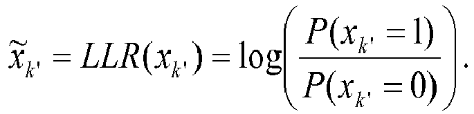
- The
deinterleaver 240 next deinterleaves the LLR values obtained fromdemodulator 230. Deinterleaving causes the errors to be well-spread out in time. After deinterleaving, the LLR values are used as soft input by the FEC decoder to correct errors such that the number of errors in the received bit stream q̃l may be minimized. - The quality of the received signal is evaluated by calculating the bit error rate (BER) of q̃l

- The BER resulting depends on the modulation type, channel conditions and the demodulation and decoding method applied at the receiver. Lower BER may be achieved when better reliability information (LLR) is obtained from demodulation. Especially when channel conditions cannot be estimated accurately, reducing the BER is challenging.
- For various modulation and coding schemes, one way of achieving a lower BER in a given channel condition is iterative demodulation and decoding. Examples of such modulating and coding schemes include various types of phase shift keying and orthogonal frequency-division multiplexing (OFDM). Whereas in the first case described above the signal is demodulated and decoded once, in case of iterative demodulation and decoding, this process is repeated with the aim of improving the BER in the consecutive iterations.
- Specifically, the incoming data ỹk' is processed by the full demodulation, deinterleaving, and FEC decoder methods to obtain q̃l . Then the output of the FEC decoder is used to demodulate the signal once again, by correcting the (a-priori) input data using the new (extrinsic) information obtained from the FEC decoder.
-
FIG. 3 illustrates a block diagram of a digital receiver baseband system using iterative demodulation and decoding. The iterative receiver system includes the same basic elements as the receiver system inFIG. 2 , but adds aniterative FEC encoder 360,iterative interleaver 370, interleavememory 372, andsymbol buffer 332. Further, thedemodulator 230 is replaced with an aposteriori probability demodulator 330. In case of a digital reception system including a hard-output FEC decoder, the output is re-encoded by theiterative FEC encoder 360 and interleaved by theiterative interleaver 370 to produce extrinsic information z̃k . The aposteriori demodulator 330 then performs a second demodulation using the extrinsic information z̃k produce an improved estimate of the received signal. Further, thesymbol buffer 332 is needed in order to store the incoming data ỹk , for the second iteration of demodulation processing. This is because of the additional delay introduced by the de-interleaver. In order to perform the demodulation operation in the second iteration, the corresponding extrinsic information z̃k needs to later be available. Further, theinterleave memory 372 is additional memory needed to store data for use by theiterative interleaver 370. -
FIG. 4 illustrates a block diagram of a second embodiment of a digital receiver baseband system using iterative demodulation. The second embodiment includes a soft-input-soft-output (SISO)decoder 450. TheSISO decoder 450 generates soft output values corresponding to encoded bits so the re-encoding is not needed. This second iterative receive system includes the same basic elements as the receiver system inFIG. 2 , but addsiterative interleaver 370, interleavememory 372, andsymbol buffer 332. As above, thedemodulator 230 is replaced with an aposteriori probability demodulator 330. The outputs of the SISO decoder are then interleaved by theiterative interleaver 370 and demodulated using a posteriori information in the aposteriori probability demodulator 330. - The changes required to implement the iterative demodulation will increase the area and/or software complexity of the receiver, thereby increasing cost of the resulting receiver. So lower BER is achieved but at a higher system cost.
- In case of some wireless standards, long interleavers are added to help correct the time selective fading that may occur in the wireless channel. This is especially the case with broadcast standards. When the long interleaver is present, supporting iterative demodulation and coding becomes excessively memory intensive because of the additional input buffer and interleave memories.
- For a quantitative example the digital audio broadcasting (DAB) standard may be considered. In the DAB standard, a time (de)interleaving length of 384 ms is required. Assuming a receiver that receives all available services, this translates to about a 330 kbyte deinterleaving memory (assuming 5 bits per LLR value), which is already present in the system for (open-loop) reception. As DAB uses DQPSK (differential QPSK) modulation, at the input side each two LLR values correspond to a complex value of a 16 bit real value and a 16 bit imaginary value. As a result, when iterative demodulation and decoding is done, the symbol buffer memory becomes 330 * 16 (bits per real/imaginary) / 5 bits per LLR ≈ 1Mbyte. Additionally, an interleave memory is needed that will be 330*R/5 where R is the coding rate and 5-bit soft inputs are assumed. For R=2, the required interleaver memory will be 33 kbyte for hard feedback and 165kbyte for soft feedback.
- Because of the large memory requirements, supporting iterative demodulation and coding becomes too expensive for broadcast reception systems. The embodiments described below reduce memory requirements by using methods to limit the input buffer memory required for iterative demodulation and decoding.
- In an iterative baseband receiver it may be possible to use a fraction of the precision in the symbol buffer data for the second iteration. During the first iteration, full precision input is used because no storage is required at this stage. For the second iteration, as the information from the first iteration is there to assist the demodulation, even a much lower precision may yield a high performance. Further, full precision extrinsic information z̃k may be converted to a lower precision and stored for use in the next iteration. As discussed below simulations have been run to verify that high performance may still be obtained by using a reduced precision information from the first iteration. Further, compression may also be applied to data stored in the interleave memory. Thus, the embodiments described below may take two measures in order to limit the amount of memory required because of iterative reception: compression of bits in the symbol buffer; and compression of bits at the interleave memory.
-
FIG. 5 illustrates a block diagram of a third embodiment of a digital receiver baseband system using iterative demodulation. The digital receiver baseband system ofFIG. 5 is the same as the digital receiver baseband system ofFIG. 3 except for the addition of compression of the data stored in thesymbol memory 332 and theinterleave memory 372. A symbol compressor/decompressor 534 compresses the received symbols that are then stored in thesymbol memory 332. The symbol compressor/decompressor 534 may also decompress compressed symbols stored in thesymbol memory 332 for use in a later demodulation iteration. The symbol compressor/decompressor 534 may use lossy compression, lossless compression, or a combination of lossy and lossless compression. Some (lossless or almost lossless) compression may already applied as the data is received. However, additional lossy compression is performed only after the data has been used for the initial demodulation. For this reason, the loss in precision does not affect the result of the first iteration. Because the second iteration may use the feedback data that leads to improved performance, the demodulator may tolerate the lowered precision and does not suffer much performance loss versus the situation where the uncompressed symbols are stored. - In a similar manner, a LLR compressor/
decompressor 574 may compress the LLR data that needs to be stored and then deinterleaved. Then when the data is to be deinterleaved, the LLR compressor/decompressor 574 may decompress the interleaved LLR data stored in theinterleave memory 372. Again, LLR compressor/decompressor 574 may use lossy compression, lossless compression, or a combination of lossy and lossless compression. - Various elements of the digital receiver baseband system of
FIG. 5 may be implemented by software running on a processor. For example any of the a posterioriprobability demodulator 330,deinterleaver 240,FEC decoder 250,FEC encoder 360,interleaver 370, symbol compressor/decompressor 534, and LLR compressor/decompressor 574 may be implemented in this way, either individually or in any combination. Alternatively, these elements may be implemented as dedicated circuits that may be implemented in a single integrated circuit or multiple integrated circuits. -
FIG. 6 illustrates a block diagram of a fourth embodiment of a digital receiver baseband system using iterative demodulation. The digital receiver baseband system ofFIG. 6 is the same as the digital receiver baseband system ofFIG. 4 except for the addition of compression of the data stored in thesymbol memory 332 and theinterleave memory 372. Further, the compression of the data stored in thesymbol memory 332 and theinterleave memory 372 may be accomplished in the same way as described inFIG. 5 . - Various elements of the digital receiver baseband system of
FIG. 6 may be implemented by software running on a processor. For example any of the a posterioriprobability demodulator 330,deinterleaver 240,SISO decoder 450,interleaver 370, symbol compressor/decompressor 534, and LLR compressor/decompressor 574 may be implemented in this way, either individually or in any combination. Alternatively, these elements may be implemented as dedicated circuits that may be implemented in a single integrated circuit or multiple integrated circuits. - The operation of the third embodiment has been modeled with matlab simulations. The simulations are based on a floating point simulation chain of the DAB standard assuming perfect synchronization. To be able to compare the effect of lossy compression in the form of reduced-precision quantization the following simulations have been run for several channel conditions:
- reference simulation (iterative demodulation and decoding with floating point values); and
- compressed symbol buffer simulation (iterative demodulation and decoding with symbol buffer compressed after the first demodulation as described above)
- Simulations have been run for various channel models with different parameters.
FIGs. 7 and8 illustrate the results of the simulation. The results are a plot of bit error rate (BER) versus signal to noise ratio (Eb/N0). The reference case corresponds to floating point matlab simulation. The fixed-point reference case of 16-bit precision is assumed to be same curve or very close. The remaining two curves correspond to 8-bit and 4-bit precision. The performance is measured at the requiredBER level 10-4. In both 8-bit and 4-bit precision cases, decrease of gain due to compression was found to be 0.3dB at most, while the memory requirement for the symbol buffer was decreased by 75% for the 4-bit case. In each simulation, a Cenelec SFN channel is used and 4-bit quantization is applied to the symbol data. The LLR data is kept at 5-bit precision, so here the effect of symbol buffer compression is seen. The multipath model used is based on COST207 channel model and an SFN Cenelec channel is simulated in this case. TI35 corresponds to the specific DAB profile simulated, andNTF=1000 denotes that 1000 DAB transport frames have been simulated to calculate the given BER figures. The plots shown inFIGs. 7 and8 use two different values for the Doppler frequency Fd. - The embodiments described above may be applied to all wireless standards for broadcast, networking, cellular, etc. applications. The advantages are especially seen in case of broadcast standards or other applications which specify long interleavers and therefore require a large buffer memory for closed-loop operation.
- Further, as described above various types and combinations of compression may be used to compress the symbol and LLR data. Also, only the symbol data or only the LLR data may be compressed.
- It should be noted that various aspects of the above embodiments may be combined resulting in other embodiments. Also, various steps in the methods may be performed in a different order or simultaneously. Also various aspects of the embodiments above may be implemented using processors and computer instructions to result in a specific machine implementing the embodiment. Also, portions of the embodiments above may be implemented using ASICs or other specific hardware elements.
- As used herein, the term "processor" will be understood to encompass a variety of devices such as microprocessors, field-programmable gate arrays (FPGAs), application-specific integrated circuits (ASICs), and other similar processing and computing devices.
- It should be appreciated by those skilled in the art that any block diagrams herein represent conceptual views of illustrative circuitry embodying the principles of the invention.
- Although the various exemplary embodiments have been described in detail with particular reference to certain exemplary aspects thereof, it should be understood that the invention is capable of other embodiments and its details are capable of modifications in various obvious respects. As is readily apparent to those skilled in the art, variations and modifications can be effected while remaining within the spirit and scope of the invention. Accordingly, the foregoing disclosure, description, and figures are for illustrative purposes only and do not in any way limit the invention, which is defined only by the claims.
Claims (14)
- A receiver, comprising:a posteriori probability demodulator configured to receive an input digital signal and output demodulated data;a deinterleaver configured to deinterleave the demodulated data;a forward error correction (FEC) decoder configured to error correct the demodulated data;a FEC encoder configured to encode the error corrected demodulated data;an interleaver configured to interleave the FEC encoded data and output the interleaved FEC encoded data to the posteriori probability demodulator; anda symbol compressor/decompressor configured to compress symbol data from the a posteriori demodulator and store the compressed data in a symbol memory and configured to decompress compressed symbol data stored in the symbol memory.
- The receiver of claim 1, wherein compressing the symbol data includes quantizing the symbol data.
- The receiver of claim 1, wherein compressing the symbol data includes using one of lossy compression, lossless compression, and lossless and lossy compression.
- The receiver of claim 1, further comprising a log likelihood ratio (LLR) compressor/decompressor configured to compress LLR data from the interleaver and store the compressed LLR data in an interleave memory and configured to decompress compressed LLR data stored in the interleave memory.
- The receiver of claim 4, wherein compressing the LLR data includes quantizing the LLR data.
- The receiver of claim 4, wherein compressing the symbol data includes using one of lossy compression, lossless compression, and lossless and lossy compression.
- A receiver, comprising:a posteriori probability demodulator configured to receive an input digital signal and output demodulated data;a deinterleaver configured to deinterleave the demodulated data;a soft input soft output (SISO) decoder configured to decode the demodulated data;an interleaver configured to interleave the demodulated data and output the interleaved demodulated data to the posteriori probability demodulator; anda symbol compressor/decompressor configured to compress symbol data from the a posteriori demodulator and store the compressed data in a symbol memory and configured to decompress compressed symbol data stored in the symbol memory.
- The receiver of claim 7, wherein compressing the symbol data includes quantizing the symbol data.
- The receiver of claim 7, wherein compressing the symbol data includes using one of lossy compression, lossless compression, and lossless and lossy compression.
- The receiver of claim 7, further comprising a log likelihood ratio (LLR) compressor/decompressor configured to compress LLR data from the interleaver and store the compressed LLR data in an interleave memory and configured to decompress compressed LLR data stored in the interleave memory;.
- The reciever of claim 10, wherein compressing the LLR data includes quantizing the LLR data.
- The receiver of claim 10, wherein compressing the symbol data includes using one of lossy compression, lossless compression, and lossless and lossy compression.
- A non-transitory machine-readable storage medium encoded with instructions for execution by a processor in a receiver, comprising:instructions for a posteriori probability demodulating an input digital signal and outputting demodulated data;instructions for deinterleaving the demodulated data;instructions for a forward error correction (FEC) decoding the demodulated data;instructions for FEC encoding the error corrected demodulated data;instructions for interleaving the FEC encoded data;instructions for compressing symbol data from the demodulated data and storing the compressed data in a symbol memory; andinstructions for decompressing compressed symbol data stored in the symbol memory.
- A non-transitory machine-readable storage medium encoded with instructions for execution by a processor in a receiver, comprising:instructions for a posteriori probability demodulating an input digital signal and outputting demodulated data;instructions for deinterleaving the demodulated data;instructions for soft input soft output (SISO) decoding the demodulated data;instructions for interleaving the SISO encoded data;instructions for compressing symbol data from the demodulated data and storing the compressed data in a symbol memory; andinstructions for decompressing compressed symbol data stored in the symbol memory.
Applications Claiming Priority (1)
| Application Number | Priority Date | Filing Date | Title |
|---|---|---|---|
| US14/461,030 US9425922B2 (en) | 2014-08-15 | 2014-08-15 | Reduced memory iterative baseband processing |
Publications (2)
| Publication Number | Publication Date |
|---|---|
| EP2985916A1 true EP2985916A1 (en) | 2016-02-17 |
| EP2985916B1 EP2985916B1 (en) | 2018-12-12 |
Family
ID=53765161
Family Applications (1)
| Application Number | Title | Priority Date | Filing Date |
|---|---|---|---|
| EP15179282.7A Active EP2985916B1 (en) | 2014-08-15 | 2015-07-31 | Reduced memory iterative demodulation and decoding |
Country Status (2)
| Country | Link |
|---|---|
| US (1) | US9425922B2 (en) |
| EP (1) | EP2985916B1 (en) |
Cited By (2)
| Publication number | Priority date | Publication date | Assignee | Title |
|---|---|---|---|---|
| EP3337070A1 (en) * | 2016-12-16 | 2018-06-20 | Nxp B.V. | Demodulation and decoding |
| EP3361659A1 (en) * | 2017-02-08 | 2018-08-15 | Nxp B.V. | Dpsk receiver module |
Families Citing this family (3)
| Publication number | Priority date | Publication date | Assignee | Title |
|---|---|---|---|---|
| US10277448B1 (en) | 2017-11-02 | 2019-04-30 | Nxp Usa, Inc. | Method for hierarchical modulation with vector processing |
| US12341610B2 (en) * | 2023-08-07 | 2025-06-24 | Hughes Network Systems, Llc | Simplified system and method for bit-interleaved coded modulation with iterative decoding (BICM-ID) |
| EP4580065A1 (en) | 2023-12-29 | 2025-07-02 | Nokia Solutions and Networks Oy | Llr compression in wireless communications networks |
Citations (4)
| Publication number | Priority date | Publication date | Assignee | Title |
|---|---|---|---|---|
| DE19934646A1 (en) * | 1999-07-16 | 2001-02-01 | Univ Dresden Tech | Method and device for iterative decoding of chained codes |
| US20050138530A1 (en) * | 2000-12-14 | 2005-06-23 | Wensheng Huang | Data compression with incremental redundancy |
| US20090103601A1 (en) * | 2007-10-17 | 2009-04-23 | Augusta Technology, Inc. | Methods for Soft Bit Companding for Time De-interleaving of Digital Signals |
| WO2014029425A1 (en) * | 2012-08-21 | 2014-02-27 | Abilis Systems Sarl | Soft metrics compressing method |
Family Cites Families (8)
| Publication number | Priority date | Publication date | Assignee | Title |
|---|---|---|---|---|
| IL104636A (en) * | 1993-02-07 | 1997-06-10 | Oli V R Corp Ltd | Apparatus and method for encoding and decoding digital signals |
| US6671338B1 (en) * | 1998-11-12 | 2003-12-30 | Hughes Electronics Corporation | Combined interference cancellation with FEC decoding for high spectral efficiency satellite communications |
| US7538694B2 (en) * | 1999-01-29 | 2009-05-26 | Mossman Holdings Llc | Network device with improved storage density and access speed using compression techniques |
| US7434145B2 (en) * | 2003-04-02 | 2008-10-07 | Qualcomm Incorporated | Extracting soft information in a block-coherent communication system |
| KR101442837B1 (en) * | 2008-02-23 | 2014-09-23 | 삼성전자주식회사 | Turbo decoder device and method |
| KR101450759B1 (en) * | 2008-07-07 | 2014-10-16 | 삼성전자주식회사 | Method and appatus for combining hibrid automatic repeat request data in a wireless communication system |
| EP2391079A1 (en) * | 2010-05-25 | 2011-11-30 | Nxp B.V. | A mobile OFDM receiver with intercarrier interference compensation |
| WO2012175636A1 (en) | 2011-06-22 | 2012-12-27 | Nxp B.V. | Two-dimensional iterative processing for dab receivers based on trellis-decomposition |
-
2014
- 2014-08-15 US US14/461,030 patent/US9425922B2/en active Active
-
2015
- 2015-07-31 EP EP15179282.7A patent/EP2985916B1/en active Active
Patent Citations (4)
| Publication number | Priority date | Publication date | Assignee | Title |
|---|---|---|---|---|
| DE19934646A1 (en) * | 1999-07-16 | 2001-02-01 | Univ Dresden Tech | Method and device for iterative decoding of chained codes |
| US20050138530A1 (en) * | 2000-12-14 | 2005-06-23 | Wensheng Huang | Data compression with incremental redundancy |
| US20090103601A1 (en) * | 2007-10-17 | 2009-04-23 | Augusta Technology, Inc. | Methods for Soft Bit Companding for Time De-interleaving of Digital Signals |
| WO2014029425A1 (en) * | 2012-08-21 | 2014-02-27 | Abilis Systems Sarl | Soft metrics compressing method |
Non-Patent Citations (4)
| Title |
|---|
| ARIYOSHI M ET AL: "Improvement on turbo code decoder by updating redundant likelihood information", PROC-, IEEE 59TH VEHICULAR TECHNOLOGY CONFERENCE, VTC 2004-SPRING MILAN, ITALY, vol. 2, 17 May 2004 (2004-05-17) - 19 May 2004 (2004-05-19), pages 1014 - 1018, XP010766064, ISBN: 978-0-7803-8255-8, DOI: 10.1109/VETECS.2004.1388984 * |
| MATTEO DANIELI ET AL: "Maximum Mutual Information Vector Quantization of Log-Likelihood Ratios for Memory Efficient HARQ Implementations", DATA COMPRESSION CONFERENCE (DCC), 2010, IEEE, PISCATAWAY, NJ, USA, 24 March 2010 (2010-03-24), pages 30 - 39, XP031661639, ISBN: 978-1-4244-6425-8 * |
| ROSATI S ET AL: "LLR Compression for BICM Systems Using Large Constellations", IEEE TRANSACTIONS ON COMMUNICATIONS, IEEE SERVICE CENTER, PISCATAWAY, NJ. USA, vol. 61, no. 7, 1 July 2013 (2013-07-01), pages 2864 - 2875, XP011522193, ISSN: 0090-6778, DOI: 10.1109/TCOMM.2013.052113.120776 * |
| XIAODONG LI ET AL: "Bit-Interleaved Coded Modulation With Iterative Decoding and 8PSK Signaling", IEEE TRANSACTIONS ON COMMUNICATIONS, IEEE SERVICE CENTER, PISCATAWAY, NJ. USA, vol. 50, no. 8, 1 August 2002 (2002-08-01), XP011070981, ISSN: 0090-6778 * |
Cited By (3)
| Publication number | Priority date | Publication date | Assignee | Title |
|---|---|---|---|---|
| EP3337070A1 (en) * | 2016-12-16 | 2018-06-20 | Nxp B.V. | Demodulation and decoding |
| US10097382B2 (en) | 2016-12-16 | 2018-10-09 | Nxp B.V. | Demodulation and decoding |
| EP3361659A1 (en) * | 2017-02-08 | 2018-08-15 | Nxp B.V. | Dpsk receiver module |
Also Published As
| Publication number | Publication date |
|---|---|
| US20160050047A1 (en) | 2016-02-18 |
| EP2985916B1 (en) | 2018-12-12 |
| US9425922B2 (en) | 2016-08-23 |
Similar Documents
| Publication | Publication Date | Title |
|---|---|---|
| US10574390B2 (en) | Systems and methods for advanced iterative decoding and channel estimation of concatenated coding systems | |
| US20200295786A1 (en) | Adaptive-SCL Polar Decoder | |
| US9425922B2 (en) | Reduced memory iterative baseband processing | |
| WO2010047390A1 (en) | Wireless relay device, wireless receiving device and decoding method | |
| US9680602B2 (en) | Bit coding device, bit decoding device, transmission device, reception device, bit coding method, bit decoding method, transmission method, reception method, and program | |
| US10158390B2 (en) | Signal processing using quantized symbols | |
| CN108206794B (en) | Receiver, integrated circuit device and signal demodulation method for communication system | |
| EP2538597B1 (en) | Method and apparatus for transmitting and receiving data in a broadcasting system | |
| EP3361659B1 (en) | Dpsk receiver module | |
| US7734983B2 (en) | Input control device and input control method | |
| Zhang et al. | Performance Analysis of Concatenated Turbo Coding Scheme over DVB-T Transmission Channel | |
| El-Demerdash et al. | Error reduction due to carrier frequency offset in OFDM system using turbo codes | |
| CN103795488A (en) | Extrinsic information correction method of iteration demodulation system |
Legal Events
| Date | Code | Title | Description |
|---|---|---|---|
| PUAI | Public reference made under article 153(3) epc to a published international application that has entered the european phase |
Free format text: ORIGINAL CODE: 0009012 |
|
| AK | Designated contracting states |
Kind code of ref document: A1 Designated state(s): AL AT BE BG CH CY CZ DE DK EE ES FI FR GB GR HR HU IE IS IT LI LT LU LV MC MK MT NL NO PL PT RO RS SE SI SK SM TR |
|
| AX | Request for extension of the european patent |
Extension state: BA ME |
|
| 17P | Request for examination filed |
Effective date: 20160817 |
|
| RBV | Designated contracting states (corrected) |
Designated state(s): AL AT BE BG CH CY CZ DE DK EE ES FI FR GB GR HR HU IE IS IT LI LT LU LV MC MK MT NL NO PL PT RO RS SE SI SK SM TR |
|
| STAA | Information on the status of an ep patent application or granted ep patent |
Free format text: STATUS: EXAMINATION IS IN PROGRESS |
|
| 17Q | First examination report despatched |
Effective date: 20170213 |
|
| REG | Reference to a national code |
Ref country code: DE Ref legal event code: R079 Ref document number: 602015021148 Country of ref document: DE Free format text: PREVIOUS MAIN CLASS: H03M0013290000 Ipc: H03M0013000000 |
|
| GRAP | Despatch of communication of intention to grant a patent |
Free format text: ORIGINAL CODE: EPIDOSNIGR1 |
|
| STAA | Information on the status of an ep patent application or granted ep patent |
Free format text: STATUS: GRANT OF PATENT IS INTENDED |
|
| RIC1 | Information provided on ipc code assigned before grant |
Ipc: H04L 1/20 20060101ALI20180618BHEP Ipc: H03M 13/00 20060101AFI20180618BHEP Ipc: H03M 7/30 20060101ALI20180618BHEP Ipc: H03M 13/37 20060101ALI20180618BHEP Ipc: H04L 1/00 20060101ALI20180618BHEP Ipc: H03M 13/29 20060101ALI20180618BHEP |
|
| INTG | Intention to grant announced |
Effective date: 20180705 |
|
| GRAS | Grant fee paid |
Free format text: ORIGINAL CODE: EPIDOSNIGR3 |
|
| GRAA | (expected) grant |
Free format text: ORIGINAL CODE: 0009210 |
|
| STAA | Information on the status of an ep patent application or granted ep patent |
Free format text: STATUS: THE PATENT HAS BEEN GRANTED |
|
| AK | Designated contracting states |
Kind code of ref document: B1 Designated state(s): AL AT BE BG CH CY CZ DE DK EE ES FI FR GB GR HR HU IE IS IT LI LT LU LV MC MK MT NL NO PL PT RO RS SE SI SK SM TR |
|
| REG | Reference to a national code |
Ref country code: GB Ref legal event code: FG4D |
|
| REG | Reference to a national code |
Ref country code: CH Ref legal event code: EP |
|
| REG | Reference to a national code |
Ref country code: AT Ref legal event code: REF Ref document number: 1077331 Country of ref document: AT Kind code of ref document: T Effective date: 20181215 |
|
| REG | Reference to a national code |
Ref country code: DE Ref legal event code: R096 Ref document number: 602015021148 Country of ref document: DE |
|
| REG | Reference to a national code |
Ref country code: IE Ref legal event code: FG4D |
|
| REG | Reference to a national code |
Ref country code: NL Ref legal event code: MP Effective date: 20181212 |
|
| REG | Reference to a national code |
Ref country code: LT Ref legal event code: MG4D |
|
| PG25 | Lapsed in a contracting state [announced via postgrant information from national office to epo] |
Ref country code: ES Free format text: LAPSE BECAUSE OF FAILURE TO SUBMIT A TRANSLATION OF THE DESCRIPTION OR TO PAY THE FEE WITHIN THE PRESCRIBED TIME-LIMIT Effective date: 20181212 Ref country code: BG Free format text: LAPSE BECAUSE OF FAILURE TO SUBMIT A TRANSLATION OF THE DESCRIPTION OR TO PAY THE FEE WITHIN THE PRESCRIBED TIME-LIMIT Effective date: 20190312 Ref country code: LT Free format text: LAPSE BECAUSE OF FAILURE TO SUBMIT A TRANSLATION OF THE DESCRIPTION OR TO PAY THE FEE WITHIN THE PRESCRIBED TIME-LIMIT Effective date: 20181212 Ref country code: NO Free format text: LAPSE BECAUSE OF FAILURE TO SUBMIT A TRANSLATION OF THE DESCRIPTION OR TO PAY THE FEE WITHIN THE PRESCRIBED TIME-LIMIT Effective date: 20190312 Ref country code: LV Free format text: LAPSE BECAUSE OF FAILURE TO SUBMIT A TRANSLATION OF THE DESCRIPTION OR TO PAY THE FEE WITHIN THE PRESCRIBED TIME-LIMIT Effective date: 20181212 Ref country code: HR Free format text: LAPSE BECAUSE OF FAILURE TO SUBMIT A TRANSLATION OF THE DESCRIPTION OR TO PAY THE FEE WITHIN THE PRESCRIBED TIME-LIMIT Effective date: 20181212 Ref country code: FI Free format text: LAPSE BECAUSE OF FAILURE TO SUBMIT A TRANSLATION OF THE DESCRIPTION OR TO PAY THE FEE WITHIN THE PRESCRIBED TIME-LIMIT Effective date: 20181212 |
|
| REG | Reference to a national code |
Ref country code: AT Ref legal event code: MK05 Ref document number: 1077331 Country of ref document: AT Kind code of ref document: T Effective date: 20181212 |
|
| PG25 | Lapsed in a contracting state [announced via postgrant information from national office to epo] |
Ref country code: AL Free format text: LAPSE BECAUSE OF FAILURE TO SUBMIT A TRANSLATION OF THE DESCRIPTION OR TO PAY THE FEE WITHIN THE PRESCRIBED TIME-LIMIT Effective date: 20181212 Ref country code: RS Free format text: LAPSE BECAUSE OF FAILURE TO SUBMIT A TRANSLATION OF THE DESCRIPTION OR TO PAY THE FEE WITHIN THE PRESCRIBED TIME-LIMIT Effective date: 20181212 Ref country code: SE Free format text: LAPSE BECAUSE OF FAILURE TO SUBMIT A TRANSLATION OF THE DESCRIPTION OR TO PAY THE FEE WITHIN THE PRESCRIBED TIME-LIMIT Effective date: 20181212 Ref country code: GR Free format text: LAPSE BECAUSE OF FAILURE TO SUBMIT A TRANSLATION OF THE DESCRIPTION OR TO PAY THE FEE WITHIN THE PRESCRIBED TIME-LIMIT Effective date: 20190313 |
|
| PG25 | Lapsed in a contracting state [announced via postgrant information from national office to epo] |
Ref country code: NL Free format text: LAPSE BECAUSE OF FAILURE TO SUBMIT A TRANSLATION OF THE DESCRIPTION OR TO PAY THE FEE WITHIN THE PRESCRIBED TIME-LIMIT Effective date: 20181212 |
|
| PG25 | Lapsed in a contracting state [announced via postgrant information from national office to epo] |
Ref country code: PT Free format text: LAPSE BECAUSE OF FAILURE TO SUBMIT A TRANSLATION OF THE DESCRIPTION OR TO PAY THE FEE WITHIN THE PRESCRIBED TIME-LIMIT Effective date: 20190412 Ref country code: IT Free format text: LAPSE BECAUSE OF FAILURE TO SUBMIT A TRANSLATION OF THE DESCRIPTION OR TO PAY THE FEE WITHIN THE PRESCRIBED TIME-LIMIT Effective date: 20181212 Ref country code: PL Free format text: LAPSE BECAUSE OF FAILURE TO SUBMIT A TRANSLATION OF THE DESCRIPTION OR TO PAY THE FEE WITHIN THE PRESCRIBED TIME-LIMIT Effective date: 20181212 Ref country code: CZ Free format text: LAPSE BECAUSE OF FAILURE TO SUBMIT A TRANSLATION OF THE DESCRIPTION OR TO PAY THE FEE WITHIN THE PRESCRIBED TIME-LIMIT Effective date: 20181212 |
|
| PG25 | Lapsed in a contracting state [announced via postgrant information from national office to epo] |
Ref country code: EE Free format text: LAPSE BECAUSE OF FAILURE TO SUBMIT A TRANSLATION OF THE DESCRIPTION OR TO PAY THE FEE WITHIN THE PRESCRIBED TIME-LIMIT Effective date: 20181212 Ref country code: SM Free format text: LAPSE BECAUSE OF FAILURE TO SUBMIT A TRANSLATION OF THE DESCRIPTION OR TO PAY THE FEE WITHIN THE PRESCRIBED TIME-LIMIT Effective date: 20181212 Ref country code: RO Free format text: LAPSE BECAUSE OF FAILURE TO SUBMIT A TRANSLATION OF THE DESCRIPTION OR TO PAY THE FEE WITHIN THE PRESCRIBED TIME-LIMIT Effective date: 20181212 Ref country code: IS Free format text: LAPSE BECAUSE OF FAILURE TO SUBMIT A TRANSLATION OF THE DESCRIPTION OR TO PAY THE FEE WITHIN THE PRESCRIBED TIME-LIMIT Effective date: 20190412 Ref country code: SK Free format text: LAPSE BECAUSE OF FAILURE TO SUBMIT A TRANSLATION OF THE DESCRIPTION OR TO PAY THE FEE WITHIN THE PRESCRIBED TIME-LIMIT Effective date: 20181212 |
|
| REG | Reference to a national code |
Ref country code: DE Ref legal event code: R097 Ref document number: 602015021148 Country of ref document: DE |
|
| PLBE | No opposition filed within time limit |
Free format text: ORIGINAL CODE: 0009261 |
|
| STAA | Information on the status of an ep patent application or granted ep patent |
Free format text: STATUS: NO OPPOSITION FILED WITHIN TIME LIMIT |
|
| PG25 | Lapsed in a contracting state [announced via postgrant information from national office to epo] |
Ref country code: DK Free format text: LAPSE BECAUSE OF FAILURE TO SUBMIT A TRANSLATION OF THE DESCRIPTION OR TO PAY THE FEE WITHIN THE PRESCRIBED TIME-LIMIT Effective date: 20181212 Ref country code: AT Free format text: LAPSE BECAUSE OF FAILURE TO SUBMIT A TRANSLATION OF THE DESCRIPTION OR TO PAY THE FEE WITHIN THE PRESCRIBED TIME-LIMIT Effective date: 20181212 Ref country code: SI Free format text: LAPSE BECAUSE OF FAILURE TO SUBMIT A TRANSLATION OF THE DESCRIPTION OR TO PAY THE FEE WITHIN THE PRESCRIBED TIME-LIMIT Effective date: 20181212 |
|
| 26N | No opposition filed |
Effective date: 20190913 |
|
| PG25 | Lapsed in a contracting state [announced via postgrant information from national office to epo] |
Ref country code: MC Free format text: LAPSE BECAUSE OF FAILURE TO SUBMIT A TRANSLATION OF THE DESCRIPTION OR TO PAY THE FEE WITHIN THE PRESCRIBED TIME-LIMIT Effective date: 20181212 |
|
| REG | Reference to a national code |
Ref country code: CH Ref legal event code: PL |
|
| GBPC | Gb: european patent ceased through non-payment of renewal fee |
Effective date: 20190731 |
|
| PG25 | Lapsed in a contracting state [announced via postgrant information from national office to epo] |
Ref country code: TR Free format text: LAPSE BECAUSE OF FAILURE TO SUBMIT A TRANSLATION OF THE DESCRIPTION OR TO PAY THE FEE WITHIN THE PRESCRIBED TIME-LIMIT Effective date: 20181212 |
|
| REG | Reference to a national code |
Ref country code: BE Ref legal event code: MM Effective date: 20190731 |
|
| PG25 | Lapsed in a contracting state [announced via postgrant information from national office to epo] |
Ref country code: GB Free format text: LAPSE BECAUSE OF NON-PAYMENT OF DUE FEES Effective date: 20190731 |
|
| PG25 | Lapsed in a contracting state [announced via postgrant information from national office to epo] |
Ref country code: LI Free format text: LAPSE BECAUSE OF NON-PAYMENT OF DUE FEES Effective date: 20190731 Ref country code: CH Free format text: LAPSE BECAUSE OF NON-PAYMENT OF DUE FEES Effective date: 20190731 Ref country code: BE Free format text: LAPSE BECAUSE OF NON-PAYMENT OF DUE FEES Effective date: 20190731 Ref country code: LU Free format text: LAPSE BECAUSE OF NON-PAYMENT OF DUE FEES Effective date: 20190731 |
|
| PG25 | Lapsed in a contracting state [announced via postgrant information from national office to epo] |
Ref country code: IE Free format text: LAPSE BECAUSE OF NON-PAYMENT OF DUE FEES Effective date: 20190731 |
|
| PG25 | Lapsed in a contracting state [announced via postgrant information from national office to epo] |
Ref country code: CY Free format text: LAPSE BECAUSE OF FAILURE TO SUBMIT A TRANSLATION OF THE DESCRIPTION OR TO PAY THE FEE WITHIN THE PRESCRIBED TIME-LIMIT Effective date: 20181212 |
|
| PG25 | Lapsed in a contracting state [announced via postgrant information from national office to epo] |
Ref country code: HU Free format text: LAPSE BECAUSE OF FAILURE TO SUBMIT A TRANSLATION OF THE DESCRIPTION OR TO PAY THE FEE WITHIN THE PRESCRIBED TIME-LIMIT; INVALID AB INITIO Effective date: 20150731 Ref country code: MT Free format text: LAPSE BECAUSE OF FAILURE TO SUBMIT A TRANSLATION OF THE DESCRIPTION OR TO PAY THE FEE WITHIN THE PRESCRIBED TIME-LIMIT Effective date: 20181212 |
|
| PG25 | Lapsed in a contracting state [announced via postgrant information from national office to epo] |
Ref country code: MK Free format text: LAPSE BECAUSE OF FAILURE TO SUBMIT A TRANSLATION OF THE DESCRIPTION OR TO PAY THE FEE WITHIN THE PRESCRIBED TIME-LIMIT Effective date: 20181212 |
|
| P01 | Opt-out of the competence of the unified patent court (upc) registered |
Effective date: 20230725 |
|
| PGFP | Annual fee paid to national office [announced via postgrant information from national office to epo] |
Ref country code: FR Payment date: 20250620 Year of fee payment: 11 |
|
| PGFP | Annual fee paid to national office [announced via postgrant information from national office to epo] |
Ref country code: DE Payment date: 20250620 Year of fee payment: 11 |