EP2985740A1 - Cash cassette having a coupling between the retracting flap and a movable bottom element - Google Patents
Cash cassette having a coupling between the retracting flap and a movable bottom element Download PDFInfo
- Publication number
- EP2985740A1 EP2985740A1 EP14180741.2A EP14180741A EP2985740A1 EP 2985740 A1 EP2985740 A1 EP 2985740A1 EP 14180741 A EP14180741 A EP 14180741A EP 2985740 A1 EP2985740 A1 EP 2985740A1
- Authority
- EP
- European Patent Office
- Prior art keywords
- retracting
- bottom element
- movable bottom
- cash cassette
- value
- Prior art date
- Legal status (The legal status is an assumption and is not a legal conclusion. Google has not performed a legal analysis and makes no representation as to the accuracy of the status listed.)
- Granted
Links
Images

Classifications
-
- G—PHYSICS
- G07—CHECKING-DEVICES
- G07D—HANDLING OF COINS OR VALUABLE PAPERS, e.g. TESTING, SORTING BY DENOMINATIONS, COUNTING, DISPENSING, CHANGING OR DEPOSITING
- G07D11/00—Devices accepting coins; Devices accepting, dispensing, sorting or counting valuable papers
- G07D11/10—Mechanical details
- G07D11/12—Containers for valuable papers
- G07D11/13—Containers for valuable papers with internal means for handling valuable papers
Definitions
- the invention relates to a cash cassette comprising a receiving area for receiving a value note stack and a retracting flap delimiting this receiving area at least in part, which retracting flap is movable along a predetermined path between a retracting position and a swiveled-away position.
- the retracting flap In the retracting position, the retracting flap retains the value note stack in the receiving area, whereas, in its swiveled-away position, the retracting flap allows an automatic feeding and/or removal of notes of value into or from the cash cassette, respectively.
- a bottom unit is provided on which the notes of value of the value note stack stand with one of their edges.
- cash cassettes are known, in which the notes of value received therein stand with one of their edges on a bottom unit.
- the cash cassettes comprise retracting flaps which are movable between a swiveled-on position and a swiveled-away position.
- the retracting flap is moved from the swiveled-on position into the swiveled-away position, the received value note stack is likewise moved in the direction of an opening of the cash cassette via a press-on carriage. In doing so, the notes of value slide with their edges over the bottom unit on which they stand.
- a movable bottom element of the bottom unit on which at least a part of the notes of value of the value note stack stand at least temporarily during the movement of the retracting flap between the retracting position and the swiveled-away position is coupled to the retracting flap such that at least the movable bottom element of the bottom unit is moved together with the retracting flap between the retracting position and the swiveled-away position.
- the coupling is in particular designed such that the distance between the retracting flap and the movable bottom element always remains the same.
- the retracting flap is moved whenever a shutter for closing an opening for the automatic feeding or removal of notes of value is opened and closed.
- the retracting flap is in particular moved from the retracting position into the swiveled-away position so that the notes of value can then be removed or fed.
- the retracting flap is moved from the swiveled-away position into the retracting position so that no notes of value can slide into the area of the opening and the shutter can be safely closed.
- the retracting flap is moved from the swiveled-away position into the retracting position, the notes of value are thus moved deeper into the cash cassette.
- the movable bottom element is in particular mechanically coupled to the retracting flap so that via this mechanism it is guaranteed that the two elements are always moved together.
- the mechanical coupling between the movable element and the retracting flap may also be omitted.
- the two elements are in particular moved by different displacing units which are, however, synchronized with each other such that the movable bottom element and the retracting flap are likewise moved synchronously.
- the movable bottom element is in particular designed such that it directly contacts the retracting flap.
- a particularly simple and direct coupling is achieved.
- the retracting flap and the movable element are coupled to each other via at least one pin, the two elements being coupled to each other such that they can be rotated relative to each other.
- the movable bottom element and the retracting flap are coupled to each other in a manner similar to a hinge. In this way, a particularly simple and nevertheless safe and reliable coupling is achieved.
- the two elements can also be coupled to each other via a gear wheel mechanism.
- the movable bottom element and the retracting flap are only coupled to each other at the end portions facing the sides of the cash cassette so that between the movable bottom element and the retracting flap an opening for passing notes of value is formed at least when the retracting flap is arranged in the swiveled-away position.
- the opening is in particular at least as wide as the widest note of value to be received in the cash cassette.
- the movable bottom element is in particular a bottom plate on which the notes of value of the value note stack stand permanently.
- permanently standing it is meant that the notes of value do not only stand on this movable bottom element temporarily during feeding and/or removal but also stand with one of their edges on this bottom element during the planned storing and for example during the transport of the cash cassette.
- the movable bottom element is in particular coupled to the retracting flap such that the movable bottom element performs a linear movement.
- This linear movement is in particular directed parallel to the stacking direction in which the notes of value are stacked. In particular, this linear movement is directed parallel to the bottom and/or cover of the cash cassette.
- the entire bottom unit is moved together with the retracting flap.
- a movable bottom element i.e. a part of the bottom unit is moved but the entire bottom unit.
- at least those parts of the bottom unit on which the notes of value stand are completely moved.
- the entire value note stack is moved together with the retracting flap between the swiveled-away position and the retracting position, without the notes of value having to be moved relative to those elements on which they stand.
- the relative movement between the notes of value and the bottom unit is minimized, and thus the force to be exerted by the press-on carriage is minimized and errors are likewise reduced to a minimum.
- the movable bottom element of the afore-described embodiments corresponds to the entire bottom unit so that, in this case, the corresponding features relate to the entire bottom unit.
- the movable bottom element can also be coupled to the retracting flap such that the movable bottom element contacts the notes of value only when the retracting flap is moved.
- the movable bottom element contacts the notes of value only during a predetermined part of the predetermined path of the retracting flap during the movement thereof.
- the notes of value stand in particular on a bottom plate in which recesses are provided through which the movable bottom element can reach.
- the retracting flap When the retracting flap is moved, the movable element is lifted by the coupling with the retracting flap such that it reaches through these recesses and thus lifts the notes of value from the bottom plate and thus moves them without the notes of value having to be moved on the bottom plate.
- the movable bottom element is mounted to the housing of the cash cassette via a slotted link guide.
- the bottom element has, for example, a slotted link with which a pin connected to the cassette housing engages. Via such a slotted link guide, a well-directed guidance of the movement of the bottom element can be established in a particularly easy manner. In particular, by using an arc-shaped slotted link guide a lifting of the movable bottom element can be achieved.
- the contacted surface can in particular be a structured surface.
- a toothing can be provided on this surface.
- a coating can be applied to the surface which coating has a particularly high friction coefficient so that the friction between the notes of value and this surface is increased.
- a rubber coat can be applied to the surface.
- the movable bottom element has a toothing and when the cash cassette comprises a gear wheel and/or gear rack mechanism which is engaged with the toothing of the movable bottom element and via which the movable bottom element and the retracting flap are movable.
- the movable bottom element is moved via this gear wheel or gear rack mechanism, and, due to the coupling, the retracting flap being moved together therewith.
- the movement can also start at the retracting flap and the bottom element can be passively moved together therewith via the coupling.
- the cash cassette comprises an engagement element which is formed such that when the cash cassette is inserted into a device for handling notes of value, for example an automated teller machine, an engagement element of this device can engage with the engagement element of the cash cassette such that as a result of the engagement the movable bottom element and/or the retracting flap are moved from the retracting position into the swiveled-away position.
- a device for handling notes of value for example an automated teller machine
- an engagement element of this device can engage with the engagement element of the cash cassette such that as a result of the engagement the movable bottom element and/or the retracting flap are moved from the retracting position into the swiveled-away position.
- the movable element and/or the retracting flap are again moved from the swiveled-away position into the retracting position when the cash cassette is removed from the device for handling notes of value.
- this engagement element is also used to close the shutter and to open and close an opening for the automatic feeding and removal of notes of value so that only one single mechanism is required.
- the cash cassette can also comprise a drive unit for moving the movable bottom element and/or the retracting flap.
- this drive unit can be designed in the form of an electric motor.
- two drive units are provided, one for moving the movable bottom element and the other for moving the retracting flap.
- the two drive units are synchronized with each other such that the movements of the movable element and of the retracting flap likewise take place synchronously.
- FIG. 1 a schematic greatly simplified illustration of a cash cassette 10 according to a first embodiment is illustrated.
- the cash cassette 10 comprises a housing 12 within which a receiving area 14 for receiving a value note stack 16 is provided.
- the notes of value of the value note stack 16 stand with one of their edges, in particular their longer edges, on a bottom unit 18.
- the value note stack 16 is biased in the direction of an opening 22 for the automatic removal and for the automatic feeding of notes of value.
- the opening 22 is closable by a shutter 24.
- the shutter 24 can in particular be designed like a jalousie and be movable between a closed position shown in Figure 1 and an open position shown in Figure 2 .
- the cash cassette 10 has a retracting flap 28 pivotable about an axis 26.
- the retracting flap 28 is pivotable between a retracting position shown in Figure 1 and a swiveled-away position shown in Figure 2 . In the retracting position, the retracting flap 28 is slanted and retracts the notes of value of the value note stack 16 into the receiving area 14 so that the notes of value cannot be removed through the opening 22 and new notes of value cannot be fed either.
- the retracting flap 28 is arranged such that the notes of value can be removed through the opening 22 and new notes of value can be fed.
- the retracting flap 28 is in particular arranged in the retracting position when the shutter 24 is closed and the cash cassette is transported and not inserted in an automated teller machine or another device for handling notes of value.
- a coupling exists between the shutter 24 and the retracting flap 28 such that when opening the shutter 24 the retracting flap 28 is automatically moved from the retracting position into the swiveled-away position and when the shutter 24 is closed the retracting flap 28 is automatically moved from the swiveled-away position into the retracting position.
- a mechanical coupling exists between the retracting flap 28 and the bottom unit 18 so that at least a part of the bottom unit 18 is moved together with the retracting flap 28.
- a mechanical coupling exists between the retracting flap 28 and the bottom unit 18, by which it is guaranteed that the movement of the retracting flap 28 and of the bottom unit 18 take place synchronously with each other.
- coupling means 30 are provided which directly couple the bottom unit 18 to the retracting flap 28.
- a pin 32 is provided which couples the retracting flap 28 and the bottom unit 18 relative to each other in a rotatable manner.
- a hinge-like coupling is established hereby.
- the retracting flap 28 and the bottom unit 18 are in particular only coupled at the end portions, i.e. at those ends of the retracting flap which face the side walls of the cash cassette 10 so that therebetween a gap is formed through which the notes of value of the value note stack 16 can be moved.
- Two pins 32 are provided accordingly.
- an indirect mechanical coupling can exist between the retracting flap 28 and the bottom unit 18, for example in that these two elements are coupled to each other via a gear wheel and/or a gear rack mechanism by which it is guaranteed that, when moving one of the two elements 18, 28, the other element 18, 28 is moved as well.
- retracting flap 28 and the bottom unit 18 are moved by separate mechanisms which, however, are synchronized with each other such that the movements of the bottom unit 18 and of the retracting flap 28 likewise take place synchronously.
- the cash cassette 10 has a displacing unit 34 by which the bottom unit 18 and the retracting flap 28 can be moved.
- this unit can, for example, be designed in the form of a gear wheel and/or gear rack mechanism which is engaged with a toothing of the bottom unit 18.
- any other form of displacing units may be provided.
- the bottom unit 18 is moved which in turn, as a result of the coupling via the coupling means 30, also moves the retracting flap 28.
- the displacing unit 34 can also move the retracting flap 28 which in turn moves the bottom unit 18 via the coupling.
- two displacing units 34 are provided, one for displacing the bottom unit 18 and the other for moving the retracting flap 28.
- the displacing unit 34 is in particular designed such that it only comprises passive elements and such that an interface with the cash cassette is provided, via which interface the displacing unit 34 can be coupled to an active drive unit of devices for handling notes of value into which the cash cassette is to be inserted.
- an active drive unit of devices for handling notes of value into which the cash cassette is to be inserted it is achieved that in the cash cassette 10 itself no active drive units, in particular no motors or the like, have to be provided.
- drive units for example motors
- drive units can of course also be provided in the cash cassette 10 itself, wherein, optional, one single motor for displacing both the bottom unit 18 and the retracting flap 28 or one motor each for displacing the bottom unit 18 and the retracting flap 28 can be used.
- the entire bottom unit 18 is moved together with the retracting flap 28.
- only a part of the bottom unit 18 can be coupled to the retracting flap 28 and, accordingly, only this part of the bottom unit 18, referred to as movable bottom element in the following, be moved therewith.
- FIG 3 a detail of a cash cassette 100 according to a second embodiment is illustrated, wherein in this embodiment only the part of the bottom unit 18 directed towards the opening 22 is designed as a movable bottom element 40 and is movable together with the retracting flap 28 in the direction of the arrow P1.
- only a part of the value note stack 16 is moved together with the movable bottom element 40.
- the movement of the other part of the value note stack 16 takes place conventionally via the press-on carriage 20 which however, since the front part of the value note stack 16 is moved by means of the movable bottom element 40, has to apply a far smaller force as the press-on carriage 20 has to perform a relative movement to the bottom unit 18 only for the remaining value note stack 16.
- That upper side 42 of the movable bottom element 40 on which the notes of value stand with one of their edges is in particular provided with a toothing 44 by which the friction coefficient is increased so that it is guaranteed that the notes of value are likewise moved when the movable bottom element 40 is moved and do not slide relative thereto.
- the higher friction coefficient can also be obtained by other means, for example by a corresponding coating or a rubber coat.
- differently structured surfaces can be used which guarantee a higher friction coefficient.
- it is also possible that a smooth surface is used.
- a cash cassette 200 according to a third embodiment is schematically illustrated each time.
- the bottom unit 18 comprises a bottom plate 50 on which the notes of value of the value note stack 16 stand with one of their edges.
- recesses 52 are provided at the side of the bottom plate 50 facing the opening 22 at the side of the bottom plate 50 facing the opening 22.
- the movable bottom element 54 is coupled to the retracting flap 28 such that when the retracting flap 28 is displaced, it is lifted relative to the bottom plate 50 and projects at least temporarily during the displacement of the retracting flap 28 through the openings 52 and thus lifts those notes of value of the value note stack which are arranged in the area of the recesses 52 at least so far that they are no longer in contact with the bottom plate 50.
- these notes of value are likewise moved together with the retracting flap 28 so that the press-on carriage 20 in turn does not have to move the notes of value arranged in the area of the recesses 52.
- the movable bottom element 54 is in particular mounted to the housing 12 of the cash cassette via an arc-shaped slotted link guide 56 with a pin 58 that engages with this slotted link. Via this slotted link guide 56 the respective lifting of the movable bottom element during movement of the retracting flap 28 is easily achieved.
Landscapes
- Physics & Mathematics (AREA)
- General Physics & Mathematics (AREA)
- Pile Receivers (AREA)
Abstract
Description
- The invention relates to a cash cassette comprising a receiving area for receiving a value note stack and a retracting flap delimiting this receiving area at least in part, which retracting flap is movable along a predetermined path between a retracting position and a swiveled-away position. In the retracting position, the retracting flap retains the value note stack in the receiving area, whereas, in its swiveled-away position, the retracting flap allows an automatic feeding and/or removal of notes of value into or from the cash cassette, respectively. Further, a bottom unit is provided on which the notes of value of the value note stack stand with one of their edges.
- From documents
DE 602 14 14 T2 andDE 10 2009 021 320 A1 - In this connection, it is problematic that in the case of very full cash cassettes, it may happen that the force exerted by the press-on carriage is not sufficient to move the entire value note stack. In particular, the notes of value also have to be put upright as the retracting flap is slanted in the swiveled-on position and is arranged vertically in the swiveled-away position. Thus, if the force exerted by the press-on carriage is not sufficient, it may happen that the notes of value are not put upright as planned and do not bear against the retracting flap as intended. As a result thereof, problems may occur during the withdrawal or the deposit of notes of value.
- From
document DE 10 2009 015 047 A1 , a cassette for filling safe bags with notes of value is known. - It is the object of the invention to specify a cash cassette by means of which a safe and reliable feeding and/or removal of notes of value to the cash cassette or from the cash cassette, respectively, is possible.
- This object is solved by a cash cassette having the features of claim 1. Advantageous developments of the invention are specified in the dependent claims.
- According to the invention, a movable bottom element of the bottom unit on which at least a part of the notes of value of the value note stack stand at least temporarily during the movement of the retracting flap between the retracting position and the swiveled-away position is coupled to the retracting flap such that at least the movable bottom element of the bottom unit is moved together with the retracting flap between the retracting position and the swiveled-away position.
- Thus, it is achieved that at least those notes of value which stand on the movable bottom element do not have to be moved on the bottom unit by the press-on carriage relative to the bottom unit when the retracting flap is moved, and do not have to be moved relative to the part of the bottom unit on which they stand, i.e. on the movable bottom element. Thus, it is guaranteed that the notes of value which are received in the receiving area of a cash cassette are reliably moved together with the retracting flap and thus a safe deposit or withdrawal of notes of value is possible.
- It is particularly advantageous when the movable bottom element is coupled to the retracting flap such that the movable bottom element is moved synchronously with the retracting flap by the predetermined path. Here, the coupling is in particular designed such that the distance between the retracting flap and the movable bottom element always remains the same. Thus, it is achieved that the notes of value which stand on the movable bottom element do not have to be moved with their "feet" relative to the bottom element so that the press-on carriage only has to move a small amount of notes of value and thus, altogether, a safe movement of the notes of value within the receiving area is achieved when the retracting flap is moved.
- In particular, the retracting flap is moved whenever a shutter for closing an opening for the automatic feeding or removal of notes of value is opened and closed. When the shutter is opened, the retracting flap is in particular moved from the retracting position into the swiveled-away position so that the notes of value can then be removed or fed. In contrast thereto, when the shutter is closed, the retracting flap is moved from the swiveled-away position into the retracting position so that no notes of value can slide into the area of the opening and the shutter can be safely closed. When the retracting flap is moved from the swiveled-away position into the retracting position, the notes of value are thus moved deeper into the cash cassette. The movable bottom element is in particular mechanically coupled to the retracting flap so that via this mechanism it is guaranteed that the two elements are always moved together. In alternative embodiments, the mechanical coupling between the movable element and the retracting flap may also be omitted. In this case, the two elements are in particular moved by different displacing units which are, however, synchronized with each other such that the movable bottom element and the retracting flap are likewise moved synchronously.
- The movable bottom element is in particular designed such that it directly contacts the retracting flap. Thus, a particularly simple and direct coupling is achieved.
- In a particularly preferred embodiment, the retracting flap and the movable element are coupled to each other via at least one pin, the two elements being coupled to each other such that they can be rotated relative to each other. In particular, the movable bottom element and the retracting flap are coupled to each other in a manner similar to a hinge. In this way, a particularly simple and nevertheless safe and reliable coupling is achieved.
- In an alternative embodiment of the invention, the two elements can also be coupled to each other via a gear wheel mechanism.
- It is particularly advantageous when the movable bottom element and the retracting flap are only coupled to each other at the end portions facing the sides of the cash cassette so that between the movable bottom element and the retracting flap an opening for passing notes of value is formed at least when the retracting flap is arranged in the swiveled-away position. As a result thereof, it is achieved that the notes of value can be moved through this opening during the automatic feeding and/or removal. The opening is in particular at least as wide as the widest note of value to be received in the cash cassette.
- The movable bottom element is in particular a bottom plate on which the notes of value of the value note stack stand permanently. By "permanently standing" it is meant that the notes of value do not only stand on this movable bottom element temporarily during feeding and/or removal but also stand with one of their edges on this bottom element during the planned storing and for example during the transport of the cash cassette.
- The movable bottom element is in particular coupled to the retracting flap such that the movable bottom element performs a linear movement. This linear movement is in particular directed parallel to the stacking direction in which the notes of value are stacked. In particular, this linear movement is directed parallel to the bottom and/or cover of the cash cassette.
- In a particularly preferred embodiment, the entire bottom unit is moved together with the retracting flap. Thus, not only a movable bottom element, i.e. a part of the bottom unit is moved but the entire bottom unit. In particular, at least those parts of the bottom unit on which the notes of value stand are completely moved. Thus, it is achieved that the entire value note stack is moved together with the retracting flap between the swiveled-away position and the retracting position, without the notes of value having to be moved relative to those elements on which they stand. Thus, it is achieved that the relative movement between the notes of value and the bottom unit is minimized, and thus the force to be exerted by the press-on carriage is minimized and errors are likewise reduced to a minimum.
- In this embodiment, thus the movable bottom element of the afore-described embodiments corresponds to the entire bottom unit so that, in this case, the corresponding features relate to the entire bottom unit.
- In an alternative embodiment of the invention, the movable bottom element can also be coupled to the retracting flap such that the movable bottom element contacts the notes of value only when the retracting flap is moved. In particular, the movable bottom element contacts the notes of value only during a predetermined part of the predetermined path of the retracting flap during the movement thereof.
- In this embodiment, the notes of value stand in particular on a bottom plate in which recesses are provided through which the movable bottom element can reach. When the retracting flap is moved, the movable element is lifted by the coupling with the retracting flap such that it reaches through these recesses and thus lifts the notes of value from the bottom plate and thus moves them without the notes of value having to be moved on the bottom plate.
- By lifting it is in particular generally meant that the notes of value no longer contact the bottom plate and are arranged at a predetermined distance thereto.
- It is particularly advantageous when the movable bottom element is mounted to the housing of the cash cassette via a slotted link guide. For this, the bottom element has, for example, a slotted link with which a pin connected to the cassette housing engages. Via such a slotted link guide, a well-directed guidance of the movement of the bottom element can be established in a particularly easy manner. In particular, by using an arc-shaped slotted link guide a lifting of the movable bottom element can be achieved.
- It is particularly advantageous when at least at the surface of the movable bottom element contacting the notes of value of the value note stack means for increasing the friction between the movable bottom element and the notes of value are provided. For this, the contacted surface can in particular be a structured surface. For example, a toothing can be provided on this surface. Alternatively, also a coating can be applied to the surface which coating has a particularly high friction coefficient so that the friction between the notes of value and this surface is increased. Especially a rubber coat can be applied to the surface. By increasing the friction coefficient, it is achieved that the notes of value can be safely moved together with the movable bottom element when the latter is moved and will not slip so easily.
- Further, it is advantageous when the movable bottom element has a toothing and when the cash cassette comprises a gear wheel and/or gear rack mechanism which is engaged with the toothing of the movable bottom element and via which the movable bottom element and the retracting flap are movable. In this embodiment, the movable bottom element is moved via this gear wheel or gear rack mechanism, and, due to the coupling, the retracting flap being moved together therewith. In an alternative embodiment of the invention, the movement can also start at the retracting flap and the bottom element can be passively moved together therewith via the coupling.
- Further, it is advantageous when the cash cassette comprises an engagement element which is formed such that when the cash cassette is inserted into a device for handling notes of value, for example an automated teller machine, an engagement element of this device can engage with the engagement element of the cash cassette such that as a result of the engagement the movable bottom element and/or the retracting flap are moved from the retracting position into the swiveled-away position. Thus, it is achieved that an active drive unit can be dispensed with. Further, it is achieved that a displacement of the retracting flap and of the bottom unit will not be forgotten. Thus, error-proneness is reduced to a minimum.
- Advantageously, due to this engagement, the movable element and/or the retracting flap are again moved from the swiveled-away position into the retracting position when the cash cassette is removed from the device for handling notes of value.
- It is particularly advantageous when this engagement element is also used to close the shutter and to open and close an opening for the automatic feeding and removal of notes of value so that only one single mechanism is required.
- In a further alternative embodiment of the invention, also two separate engagements can be provided for the movable bottom element and the retracting flap. In this case, in particular no direct mechanical coupling is required between the bottom element and the retracting flap.
- In a further alternative embodiment of the invention, the cash cassette can also comprise a drive unit for moving the movable bottom element and/or the retracting flap. For example, this drive unit can be designed in the form of an electric motor. Alternatively, it is likewise possible that two drive units are provided, one for moving the movable bottom element and the other for moving the retracting flap. Here, the two drive units are synchronized with each other such that the movements of the movable element and of the retracting flap likewise take place synchronously.
- Further features and advantages of the invention result from the following description which explains the invention in more detail on the basis of embodiments in connection with the enclosed Figures.
-
Figure 1 shows a schematic illustration of acash cassette 10 according to a first embodiment, with the retracting flap being arranged in a retracting position. -
Figure 2 shows a schematic illustration of the cash cassette according toFigure 1 , with the retracting flap being arranged in a swiveled-away position. -
Figure 3 shows a schematic illustration of a detail of a cash cassette according to a second embodiment. -
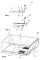
Figure 4 shows a schematic detail of a cash cassette according to a third embodiment. -
Figure 5 shows a schematic perspective illustration of the cash cassette according toFigure 4 . - In
Figure 1 , a schematic greatly simplified illustration of acash cassette 10 according to a first embodiment is illustrated. Thecash cassette 10 comprises ahousing 12 within which a receivingarea 14 for receiving avalue note stack 16 is provided. Here, the notes of value of thevalue note stack 16 stand with one of their edges, in particular their longer edges, on abottom unit 18. - By means of a biased press-on
carriage 20 thevalue note stack 16 is biased in the direction of anopening 22 for the automatic removal and for the automatic feeding of notes of value. - The
opening 22 is closable by ashutter 24. Theshutter 24 can in particular be designed like a jalousie and be movable between a closed position shown inFigure 1 and an open position shown inFigure 2 . Further, thecash cassette 10 has a retractingflap 28 pivotable about anaxis 26. The retractingflap 28 is pivotable between a retracting position shown inFigure 1 and a swiveled-away position shown inFigure 2 . In the retracting position, the retractingflap 28 is slanted and retracts the notes of value of thevalue note stack 16 into the receivingarea 14 so that the notes of value cannot be removed through theopening 22 and new notes of value cannot be fed either. In contrast thereto, in the swiveled-away position the retractingflap 28 is arranged such that the notes of value can be removed through theopening 22 and new notes of value can be fed. The retractingflap 28 is in particular arranged in the retracting position when theshutter 24 is closed and the cash cassette is transported and not inserted in an automated teller machine or another device for handling notes of value. - In particular, a coupling exists between the
shutter 24 and the retractingflap 28 such that when opening theshutter 24 the retractingflap 28 is automatically moved from the retracting position into the swiveled-away position and when theshutter 24 is closed the retractingflap 28 is automatically moved from the swiveled-away position into the retracting position. Thus, it is in particular guaranteed that, before a cash cassette is removed from a device for handling notes of value, the notes of value are moved deeper into the receivingarea 14 so that theshutter 24 can be safely closed and no notes of value can fall out of the receivingarea 14 and possibly prevent a withdrawal later on by slipping. - According to the invention, a mechanical coupling exists between the retracting
flap 28 and thebottom unit 18 so that at least a part of thebottom unit 18 is moved together with the retractingflap 28. - In the embodiment shown in
Figures 1 and 2 , a mechanical coupling exists between the retractingflap 28 and thebottom unit 18, by which it is guaranteed that the movement of the retractingflap 28 and of thebottom unit 18 take place synchronously with each other. In particular, coupling means 30 are provided which directly couple thebottom unit 18 to the retractingflap 28. In the embodiment shown inFigures 1 and 2 , apin 32 is provided which couples the retractingflap 28 and thebottom unit 18 relative to each other in a rotatable manner. In particular, a hinge-like coupling is established hereby. - The retracting
flap 28 and thebottom unit 18 are in particular only coupled at the end portions, i.e. at those ends of the retracting flap which face the side walls of thecash cassette 10 so that therebetween a gap is formed through which the notes of value of thevalue note stack 16 can be moved. Twopins 32 are provided accordingly. - In an alternative embodiment of the invention, also an indirect mechanical coupling can exist between the retracting
flap 28 and thebottom unit 18, for example in that these two elements are coupled to each other via a gear wheel and/or a gear rack mechanism by which it is guaranteed that, when moving one of the twoelements other element - In addition, it is alternatively possible that there exists no direct mechanical coupling between them at all but that the retracting
flap 28 and thebottom unit 18 are moved by separate mechanisms which, however, are synchronized with each other such that the movements of thebottom unit 18 and of the retractingflap 28 likewise take place synchronously. - In particular, the
cash cassette 10 has a displacingunit 34 by which thebottom unit 18 and the retractingflap 28 can be moved. In the embodiment shown inFigures 1 and 2 , this unit can, for example, be designed in the form of a gear wheel and/or gear rack mechanism which is engaged with a toothing of thebottom unit 18. Alternatively, also any other form of displacing units may be provided. - In the embodiment shown in
Figures 1 and 2 , by means of the displacingunit 34 thebottom unit 18 is moved which in turn, as a result of the coupling via the coupling means 30, also moves the retractingflap 28. In an alternative embodiment, the displacingunit 34 can also move the retractingflap 28 which in turn moves thebottom unit 18 via the coupling. - Further, it is alternatively possible that two displacing
units 34 are provided, one for displacing thebottom unit 18 and the other for moving the retractingflap 28. - The displacing
unit 34 is in particular designed such that it only comprises passive elements and such that an interface with the cash cassette is provided, via which interface the displacingunit 34 can be coupled to an active drive unit of devices for handling notes of value into which the cash cassette is to be inserted. Thus, it is achieved that in thecash cassette 10 itself no active drive units, in particular no motors or the like, have to be provided. - In an alternative embodiment of the invention, drive units, for example motors, can of course also be provided in the
cash cassette 10 itself, wherein, optional, one single motor for displacing both thebottom unit 18 and the retractingflap 28 or one motor each for displacing thebottom unit 18 and the retractingflap 28 can be used. - By moving the
bottom unit 18 together with the retractingflap 28 when the latter is displaced, it is achieved that the notes of value of thevalue note stack 16 do not have to be moved relative to thebottom unit 18. In particular, there is thus no risk that the force of the press-oncarriage 20 is not sufficient to move these notes of value completely in the direction of theopening 22 and to put them upright, which could otherwise result in problems during the withdrawal. Thus, a safe removal and a safe feeding of the notes of value are guaranteed. - In the embodiment shown in
Figures 1 and 2 , theentire bottom unit 18 is moved together with the retractingflap 28. In an alternative embodiment also only a part of thebottom unit 18 can be coupled to the retractingflap 28 and, accordingly, only this part of thebottom unit 18, referred to as movable bottom element in the following, be moved therewith. - In
Figure 3 , a detail of acash cassette 100 according to a second embodiment is illustrated, wherein in this embodiment only the part of thebottom unit 18 directed towards the opening 22 is designed as amovable bottom element 40 and is movable together with the retractingflap 28 in the direction of the arrow P1. Thus, only a part of thevalue note stack 16 is moved together with themovable bottom element 40. The movement of the other part of thevalue note stack 16 takes place conventionally via the press-oncarriage 20 which however, since the front part of thevalue note stack 16 is moved by means of themovable bottom element 40, has to apply a far smaller force as the press-oncarriage 20 has to perform a relative movement to thebottom unit 18 only for the remainingvalue note stack 16. - That
upper side 42 of themovable bottom element 40 on which the notes of value stand with one of their edges is in particular provided with atoothing 44 by which the friction coefficient is increased so that it is guaranteed that the notes of value are likewise moved when themovable bottom element 40 is moved and do not slide relative thereto. In an alternative embodiment of the invention, the higher friction coefficient can also be obtained by other means, for example by a corresponding coating or a rubber coat. Likewise, differently structured surfaces can be used which guarantee a higher friction coefficient. Alternatively, it is also possible that a smooth surface is used. - In
Figures 4 and 5 , acash cassette 200 according to a third embodiment is schematically illustrated each time. In this third embodiment, thebottom unit 18 comprises abottom plate 50 on which the notes of value of thevalue note stack 16 stand with one of their edges. At the side of thebottom plate 50 facing theopening 22, recesses 52 are provided. - In this embodiment, the
movable bottom element 54 is coupled to the retractingflap 28 such that when the retractingflap 28 is displaced, it is lifted relative to thebottom plate 50 and projects at least temporarily during the displacement of the retractingflap 28 through theopenings 52 and thus lifts those notes of value of the value note stack which are arranged in the area of therecesses 52 at least so far that they are no longer in contact with thebottom plate 50. By likewise moving themovable bottom element 54, these notes of value are likewise moved together with the retractingflap 28 so that the press-oncarriage 20 in turn does not have to move the notes of value arranged in the area of therecesses 52. - In this embodiment, the
movable bottom element 54 is in particular mounted to thehousing 12 of the cash cassette via an arc-shaped slottedlink guide 56 with apin 58 that engages with this slotted link. Via this slottedlink guide 56 the respective lifting of the movable bottom element during movement of the retractingflap 28 is easily achieved. -
- 10, 100, 200
- cash cassette
- 12
- housing
- 14
- receiving area
- 16
- value note stack
- 18
- bottom unit
- 20
- press-on carriage
- 22
- opening
- 24
- shutter
- 26
- axis
- 28
- retracting flap
- 30
- coupling means
- 32
- pin
- 40, 54
- movable bottom element
- 42
- surface
- 44
- toothing
- 50
- bottom plate
- 52
- recess
- 56
- slotted link guide
- 58
- pin
- P1
- direction
Claims (15)
- A cash cassette, comprising
a receiving area (14) for receiving a value note stack (16),
a retracting flap (28) movable between a retracting position and a swiveled-away position along a predetermined path, wherein the retracting flap (28) retains the value note stack (16) in the receiving area (14) in the retracting position and allows a feeding and/or removal of notes of value in the swiveled-away position, and
a bottom unit (18) on which the notes of value of the value note stack (16) stand with one of their edges,
characterized in that at least a movable bottom element (40, 54) of the bottom unit (18) on which at least a part of the value note stack (16) stands at least temporarily at least during the movement of the retracting flap (28) between the retracting position and the swiveled-away position is coupled to the retracting flap (28) such that at least the movable bottom element (40, 54) is moved together with the retracting flap (28) between the retracting position and the swiveled-away position. - The cash cassette (10, 100, 200) according to claim 1, characterized in that the movable bottom element (40, 54) is coupled to the retracting flap (28) such that the movable bottom element (40, 54) is moved synchronously with the retracting flap (28) along the predetermined path.
- The cash cassette (10, 100, 200) according to claim 1 or 2, characterized in that the movable bottom element (40, 54) is mechanically coupled to the retracting flap (28).
- The cash cassette (10, 100, 200) according to claim 3, characterized in that the movable bottom element (40, 54) contacts the retracting flap (28).
- The cash cassette (10, 100, 200) according to claim 3 or 4, characterized in that the movable bottom element (40, 54) and the retracting flap (28) are connected to each other rotatably relative to each other via at least one pin (32).
- The cash cassette (10, 100, 200) according to one of the claims 3 to 5, characterized in that the movable bottom element (40, 54) and the retracting flap (28) are coupled to each other only at the end portions facing the sides of the cash cassette (10, 100, 200) so that an opening for passing notes of value is formed between the movable bottom element (40, 54) and the retracting flap (28) at least in the swiveled-away position.
- The cash cassette (10, 100, 200) according to one of the preceding claims, characterized in that the movable bottom element (40, 54) is a bottom plate (18, 40) on which the notes of value of the value note stack (16) stand permanently.
- The cash cassette (10, 100, 200) according to one of the preceding claims, characterized in that the movable bottom element (40, 54) is coupled to the retracting flap (28) such that the movable bottom element (40, 54) performs a linear movement.
- The cash cassette (10, 100, 200) according to one of the preceding claims, characterized in that the entire bottom unit (18) is moved together with the retracting flap (28).
- The cash cassette (10, 100, 200) according to one of the claims 1 to 6, characterized in that the movable bottom element (40, 54) is coupled to the retracting flap (28) such that the movable bottom element (40, 54) contacts the notes of value only during movement of the retracting flap (28), in particular only for a part of the predetermined path.
- The cash cassette (10, 100, 200) according to claim 10, characterized in that the movable bottom element (40, 54) is coupled to the retracting flap (28) such that the movable bottom element (40, 54) performs an arc-shaped movement so that at least a part of the value note stack (16) is lifted relative to the housing bottom of the cash cassette (10, 100, 200).
- The cash cassette (10, 100, 200) according to one of the preceding claims, characterized in that the movable bottom element (40, 54) is mounted to the housing of the cash cassette (10, 100, 200) via a slotted link guide (56, 58).
- The cash cassette (10, 100, 200) according to one of the preceding claims, characterized in that at least at the surface (42) of the movable bottom element (40, 54) contacting the notes of value of the value note stack (16) means (44) for increasing the friction between the movable bottom element (40, 54) and the notes of value are provided, in particular a structured surface, for example a toothing, and/or a coating, for example a rubber coat.
- The cash cassette (10, 100, 200) according to one of the preceding claims, characterized in that the movable bottom element (40, 54) has a toothing, and that the cash cassette (10, 100, 200) comprises a gear wheel and/or gear rack mechanism which is engaged with the toothing of the movable bottom element (40, 54) and via which the movable bottom element (40, 54) and the retracting flap (28) are movable.
- The cash cassette (10, 100, 200) according to one of the preceding claims, characterized in that the cash cassette (10, 100, 200) comprises an engagement element into which during the insertion of the cash cassette (10, 100, 200) in a device for handling notes of value an engagement element of this device can engage such that by the engagement the movable bottom element (40, 54) and/or the retracting flap (28) are moved from the retracting position into the swiveled-away position.
Priority Applications (1)
| Application Number | Priority Date | Filing Date | Title |
|---|---|---|---|
| EP14180741.2A EP2985740B1 (en) | 2014-08-13 | 2014-08-13 | Cash cassette having a coupling between the retracting flap and a movable bottom element |
Applications Claiming Priority (1)
| Application Number | Priority Date | Filing Date | Title |
|---|---|---|---|
| EP14180741.2A EP2985740B1 (en) | 2014-08-13 | 2014-08-13 | Cash cassette having a coupling between the retracting flap and a movable bottom element |
Publications (2)
| Publication Number | Publication Date |
|---|---|
| EP2985740A1 true EP2985740A1 (en) | 2016-02-17 |
| EP2985740B1 EP2985740B1 (en) | 2023-10-04 |
Family
ID=51398487
Family Applications (1)
| Application Number | Title | Priority Date | Filing Date |
|---|---|---|---|
| EP14180741.2A Active EP2985740B1 (en) | 2014-08-13 | 2014-08-13 | Cash cassette having a coupling between the retracting flap and a movable bottom element |
Country Status (1)
| Country | Link |
|---|---|
| EP (1) | EP2985740B1 (en) |
Citations (7)
| Publication number | Priority date | Publication date | Assignee | Title |
|---|---|---|---|---|
| EP1710757A1 (en) * | 2005-04-07 | 2006-10-11 | NCR International, Inc. | Media cassette |
| WO2007090899A1 (en) * | 2006-02-10 | 2007-08-16 | Cts Cashpro S.P.A. | Equipment for storing in an orderly way banknotes and/or papers and the like |
| DE60219414T2 (en) | 2001-12-28 | 2007-12-13 | Mei, Inc. | Apparatus for stacking sheets with a slider having at least one laterally extendable part |
| DE102009015047A1 (en) | 2009-03-26 | 2010-09-30 | Wincor Nixdorf International Gmbh | Device for filling a thin-walled transport container with notes of value |
| DE102009021320A1 (en) | 2009-05-14 | 2010-11-18 | Wincor Nixdorf International Gmbh | Device and method for separating banknotes of a value note stack |
| WO2011150961A1 (en) * | 2010-05-31 | 2011-12-08 | Cts Electronics S.P.A. | Device for depositing or depositing and dispensing values such as banknotes or checks |
| EP2722827A1 (en) * | 2012-10-18 | 2014-04-23 | Wincor Nixdorf International GmbH | Cash box with retaining element and device for handling vouchers |
-
2014
- 2014-08-13 EP EP14180741.2A patent/EP2985740B1/en active Active
Patent Citations (7)
| Publication number | Priority date | Publication date | Assignee | Title |
|---|---|---|---|---|
| DE60219414T2 (en) | 2001-12-28 | 2007-12-13 | Mei, Inc. | Apparatus for stacking sheets with a slider having at least one laterally extendable part |
| EP1710757A1 (en) * | 2005-04-07 | 2006-10-11 | NCR International, Inc. | Media cassette |
| WO2007090899A1 (en) * | 2006-02-10 | 2007-08-16 | Cts Cashpro S.P.A. | Equipment for storing in an orderly way banknotes and/or papers and the like |
| DE102009015047A1 (en) | 2009-03-26 | 2010-09-30 | Wincor Nixdorf International Gmbh | Device for filling a thin-walled transport container with notes of value |
| DE102009021320A1 (en) | 2009-05-14 | 2010-11-18 | Wincor Nixdorf International Gmbh | Device and method for separating banknotes of a value note stack |
| WO2011150961A1 (en) * | 2010-05-31 | 2011-12-08 | Cts Electronics S.P.A. | Device for depositing or depositing and dispensing values such as banknotes or checks |
| EP2722827A1 (en) * | 2012-10-18 | 2014-04-23 | Wincor Nixdorf International GmbH | Cash box with retaining element and device for handling vouchers |
Also Published As
| Publication number | Publication date |
|---|---|
| EP2985740B1 (en) | 2023-10-04 |
Similar Documents
| Publication | Publication Date | Title |
|---|---|---|
| US9865118B2 (en) | Cassette replenishment | |
| US8261903B2 (en) | Media presenter | |
| CN106537468B (en) | Paper sheet conveying device and paper sheet processing device | |
| EP2551830A1 (en) | Media cassette | |
| CN104039672A (en) | Apparatus and method for filling thin-walled transport container | |
| JP6788446B2 (en) | Paper leaf storage device and paper leaf storage method | |
| CN102598068B (en) | Document storage assembly | |
| US8366107B2 (en) | Media presenter | |
| US9070245B2 (en) | Cash box with a partially plate-shaped closing unit and device for handling notes of value | |
| EP2985740B1 (en) | Cash cassette having a coupling between the retracting flap and a movable bottom element | |
| US10169945B2 (en) | Medium storage box and medium handling device | |
| CN104424706B (en) | Stacker mechanism and cassette for ticket | |
| CN104335254B (en) | Paper handling device | |
| US9454862B2 (en) | Cash box having a movable base tray | |
| EP3046084B1 (en) | Paper sheet receiving stacker | |
| JP2019085196A (en) | Tray for book storage installation and book storage device with tray | |
| EP2423140B1 (en) | Media presenter | |
| US9666010B2 (en) | Cash box having an adjustable belt support | |
| US9242812B2 (en) | Cash box with a blocking element for closing the gap between bottom container and retaining element | |
| KR102312025B1 (en) | Paper currency processing device | |
| JP6768160B2 (en) | Banknote handling device | |
| CN210836300U (en) | Paper money storage device and cash recycling equipment | |
| KR20140122352A (en) | Automated Teller Machine with a structure capable of maintenance easily | |
| KR20100056866A (en) | Media cassette for media dispenser | |
| KR20060113243A (en) | Automatic bill loader |
Legal Events
| Date | Code | Title | Description |
|---|---|---|---|
| PUAI | Public reference made under article 153(3) epc to a published international application that has entered the european phase |
Free format text: ORIGINAL CODE: 0009012 |
|
| AK | Designated contracting states |
Kind code of ref document: A1 Designated state(s): AL AT BE BG CH CY CZ DE DK EE ES FI FR GB GR HR HU IE IS IT LI LT LU LV MC MK MT NL NO PL PT RO RS SE SI SK SM TR |
|
| AX | Request for extension of the european patent |
Extension state: BA ME |
|
| 17P | Request for examination filed |
Effective date: 20160812 |
|
| RBV | Designated contracting states (corrected) |
Designated state(s): AL AT BE BG CH CY CZ DE DK EE ES FI FR GB GR HR HU IE IS IT LI LT LU LV MC MK MT NL NO PL PT RO RS SE SI SK SM TR |
|
| STAA | Information on the status of an ep patent application or granted ep patent |
Free format text: STATUS: EXAMINATION IS IN PROGRESS |
|
| 17Q | First examination report despatched |
Effective date: 20210415 |
|
| GRAP | Despatch of communication of intention to grant a patent |
Free format text: ORIGINAL CODE: EPIDOSNIGR1 |
|
| STAA | Information on the status of an ep patent application or granted ep patent |
Free format text: STATUS: GRANT OF PATENT IS INTENDED |
|
| INTG | Intention to grant announced |
Effective date: 20230207 |
|
| RAP1 | Party data changed (applicant data changed or rights of an application transferred) |
Owner name: DIEBOLD NIXDORF SYSTEMS GMBH |
|
| GRAS | Grant fee paid |
Free format text: ORIGINAL CODE: EPIDOSNIGR3 |
|
| GRAA | (expected) grant |
Free format text: ORIGINAL CODE: 0009210 |
|
| STAA | Information on the status of an ep patent application or granted ep patent |
Free format text: STATUS: THE PATENT HAS BEEN GRANTED |
|
| AK | Designated contracting states |
Kind code of ref document: B1 Designated state(s): AL AT BE BG CH CY CZ DE DK EE ES FI FR GB GR HR HU IE IS IT LI LT LU LV MC MK MT NL NO PL PT RO RS SE SI SK SM TR |
|
| REG | Reference to a national code |
Ref country code: GB Ref legal event code: FG4D |
|
| REG | Reference to a national code |
Ref country code: CH Ref legal event code: EP |
|
| REG | Reference to a national code |
Ref country code: DE Ref legal event code: R096 Ref document number: 602014088474 Country of ref document: DE |
|
| REG | Reference to a national code |
Ref country code: IE Ref legal event code: FG4D |
|
| REG | Reference to a national code |
Ref country code: LT Ref legal event code: MG9D |
|
| REG | Reference to a national code |
Ref country code: NL Ref legal event code: MP Effective date: 20231004 |
|
| REG | Reference to a national code |
Ref country code: AT Ref legal event code: MK05 Ref document number: 1618566 Country of ref document: AT Kind code of ref document: T Effective date: 20231004 |
|
| PG25 | Lapsed in a contracting state [announced via postgrant information from national office to epo] |
Ref country code: NL Free format text: LAPSE BECAUSE OF FAILURE TO SUBMIT A TRANSLATION OF THE DESCRIPTION OR TO PAY THE FEE WITHIN THE PRESCRIBED TIME-LIMIT Effective date: 20231004 |
|
| PG25 | Lapsed in a contracting state [announced via postgrant information from national office to epo] |
Ref country code: GR Free format text: LAPSE BECAUSE OF FAILURE TO SUBMIT A TRANSLATION OF THE DESCRIPTION OR TO PAY THE FEE WITHIN THE PRESCRIBED TIME-LIMIT Effective date: 20240105 |
|
| PG25 | Lapsed in a contracting state [announced via postgrant information from national office to epo] |
Ref country code: IS Free format text: LAPSE BECAUSE OF FAILURE TO SUBMIT A TRANSLATION OF THE DESCRIPTION OR TO PAY THE FEE WITHIN THE PRESCRIBED TIME-LIMIT Effective date: 20240204 |
|
| PG25 | Lapsed in a contracting state [announced via postgrant information from national office to epo] |
Ref country code: LT Free format text: LAPSE BECAUSE OF FAILURE TO SUBMIT A TRANSLATION OF THE DESCRIPTION OR TO PAY THE FEE WITHIN THE PRESCRIBED TIME-LIMIT Effective date: 20231004 |
|
| PG25 | Lapsed in a contracting state [announced via postgrant information from national office to epo] |
Ref country code: AT Free format text: LAPSE BECAUSE OF FAILURE TO SUBMIT A TRANSLATION OF THE DESCRIPTION OR TO PAY THE FEE WITHIN THE PRESCRIBED TIME-LIMIT Effective date: 20231004 |
|
| PG25 | Lapsed in a contracting state [announced via postgrant information from national office to epo] |
Ref country code: ES Free format text: LAPSE BECAUSE OF FAILURE TO SUBMIT A TRANSLATION OF THE DESCRIPTION OR TO PAY THE FEE WITHIN THE PRESCRIBED TIME-LIMIT Effective date: 20231004 |
|
| PG25 | Lapsed in a contracting state [announced via postgrant information from national office to epo] |
Ref country code: LT Free format text: LAPSE BECAUSE OF FAILURE TO SUBMIT A TRANSLATION OF THE DESCRIPTION OR TO PAY THE FEE WITHIN THE PRESCRIBED TIME-LIMIT Effective date: 20231004 Ref country code: IS Free format text: LAPSE BECAUSE OF FAILURE TO SUBMIT A TRANSLATION OF THE DESCRIPTION OR TO PAY THE FEE WITHIN THE PRESCRIBED TIME-LIMIT Effective date: 20240204 Ref country code: GR Free format text: LAPSE BECAUSE OF FAILURE TO SUBMIT A TRANSLATION OF THE DESCRIPTION OR TO PAY THE FEE WITHIN THE PRESCRIBED TIME-LIMIT Effective date: 20240105 Ref country code: ES Free format text: LAPSE BECAUSE OF FAILURE TO SUBMIT A TRANSLATION OF THE DESCRIPTION OR TO PAY THE FEE WITHIN THE PRESCRIBED TIME-LIMIT Effective date: 20231004 Ref country code: BG Free format text: LAPSE BECAUSE OF FAILURE TO SUBMIT A TRANSLATION OF THE DESCRIPTION OR TO PAY THE FEE WITHIN THE PRESCRIBED TIME-LIMIT Effective date: 20240104 Ref country code: AT Free format text: LAPSE BECAUSE OF FAILURE TO SUBMIT A TRANSLATION OF THE DESCRIPTION OR TO PAY THE FEE WITHIN THE PRESCRIBED TIME-LIMIT Effective date: 20231004 Ref country code: PT Free format text: LAPSE BECAUSE OF FAILURE TO SUBMIT A TRANSLATION OF THE DESCRIPTION OR TO PAY THE FEE WITHIN THE PRESCRIBED TIME-LIMIT Effective date: 20240205 |
|
| PG25 | Lapsed in a contracting state [announced via postgrant information from national office to epo] |
Ref country code: SE Free format text: LAPSE BECAUSE OF FAILURE TO SUBMIT A TRANSLATION OF THE DESCRIPTION OR TO PAY THE FEE WITHIN THE PRESCRIBED TIME-LIMIT Effective date: 20231004 Ref country code: RS Free format text: LAPSE BECAUSE OF FAILURE TO SUBMIT A TRANSLATION OF THE DESCRIPTION OR TO PAY THE FEE WITHIN THE PRESCRIBED TIME-LIMIT Effective date: 20231004 Ref country code: PL Free format text: LAPSE BECAUSE OF FAILURE TO SUBMIT A TRANSLATION OF THE DESCRIPTION OR TO PAY THE FEE WITHIN THE PRESCRIBED TIME-LIMIT Effective date: 20231004 Ref country code: NO Free format text: LAPSE BECAUSE OF FAILURE TO SUBMIT A TRANSLATION OF THE DESCRIPTION OR TO PAY THE FEE WITHIN THE PRESCRIBED TIME-LIMIT Effective date: 20240104 Ref country code: LV Free format text: LAPSE BECAUSE OF FAILURE TO SUBMIT A TRANSLATION OF THE DESCRIPTION OR TO PAY THE FEE WITHIN THE PRESCRIBED TIME-LIMIT Effective date: 20231004 Ref country code: HR Free format text: LAPSE BECAUSE OF FAILURE TO SUBMIT A TRANSLATION OF THE DESCRIPTION OR TO PAY THE FEE WITHIN THE PRESCRIBED TIME-LIMIT Effective date: 20231004 |
|
| REG | Reference to a national code |
Ref country code: DE Ref legal event code: R097 Ref document number: 602014088474 Country of ref document: DE |
|
| PG25 | Lapsed in a contracting state [announced via postgrant information from national office to epo] |
Ref country code: DK Free format text: LAPSE BECAUSE OF FAILURE TO SUBMIT A TRANSLATION OF THE DESCRIPTION OR TO PAY THE FEE WITHIN THE PRESCRIBED TIME-LIMIT Effective date: 20231004 |
|
| PG25 | Lapsed in a contracting state [announced via postgrant information from national office to epo] |
Ref country code: CZ Free format text: LAPSE BECAUSE OF FAILURE TO SUBMIT A TRANSLATION OF THE DESCRIPTION OR TO PAY THE FEE WITHIN THE PRESCRIBED TIME-LIMIT Effective date: 20231004 |
|
| PG25 | Lapsed in a contracting state [announced via postgrant information from national office to epo] |
Ref country code: SK Free format text: LAPSE BECAUSE OF FAILURE TO SUBMIT A TRANSLATION OF THE DESCRIPTION OR TO PAY THE FEE WITHIN THE PRESCRIBED TIME-LIMIT Effective date: 20231004 |
|
| PG25 | Lapsed in a contracting state [announced via postgrant information from national office to epo] |
Ref country code: SM Free format text: LAPSE BECAUSE OF FAILURE TO SUBMIT A TRANSLATION OF THE DESCRIPTION OR TO PAY THE FEE WITHIN THE PRESCRIBED TIME-LIMIT Effective date: 20231004 Ref country code: SK Free format text: LAPSE BECAUSE OF FAILURE TO SUBMIT A TRANSLATION OF THE DESCRIPTION OR TO PAY THE FEE WITHIN THE PRESCRIBED TIME-LIMIT Effective date: 20231004 Ref country code: RO Free format text: LAPSE BECAUSE OF FAILURE TO SUBMIT A TRANSLATION OF THE DESCRIPTION OR TO PAY THE FEE WITHIN THE PRESCRIBED TIME-LIMIT Effective date: 20231004 Ref country code: IT Free format text: LAPSE BECAUSE OF FAILURE TO SUBMIT A TRANSLATION OF THE DESCRIPTION OR TO PAY THE FEE WITHIN THE PRESCRIBED TIME-LIMIT Effective date: 20231004 Ref country code: EE Free format text: LAPSE BECAUSE OF FAILURE TO SUBMIT A TRANSLATION OF THE DESCRIPTION OR TO PAY THE FEE WITHIN THE PRESCRIBED TIME-LIMIT Effective date: 20231004 Ref country code: DK Free format text: LAPSE BECAUSE OF FAILURE TO SUBMIT A TRANSLATION OF THE DESCRIPTION OR TO PAY THE FEE WITHIN THE PRESCRIBED TIME-LIMIT Effective date: 20231004 Ref country code: CZ Free format text: LAPSE BECAUSE OF FAILURE TO SUBMIT A TRANSLATION OF THE DESCRIPTION OR TO PAY THE FEE WITHIN THE PRESCRIBED TIME-LIMIT Effective date: 20231004 |
|
| PLBE | No opposition filed within time limit |
Free format text: ORIGINAL CODE: 0009261 |
|
| STAA | Information on the status of an ep patent application or granted ep patent |
Free format text: STATUS: NO OPPOSITION FILED WITHIN TIME LIMIT |
|
| 26N | No opposition filed |
Effective date: 20240705 |
|
| PG25 | Lapsed in a contracting state [announced via postgrant information from national office to epo] |
Ref country code: SI Free format text: LAPSE BECAUSE OF FAILURE TO SUBMIT A TRANSLATION OF THE DESCRIPTION OR TO PAY THE FEE WITHIN THE PRESCRIBED TIME-LIMIT Effective date: 20231004 |
|
| PG25 | Lapsed in a contracting state [announced via postgrant information from national office to epo] |
Ref country code: SI Free format text: LAPSE BECAUSE OF FAILURE TO SUBMIT A TRANSLATION OF THE DESCRIPTION OR TO PAY THE FEE WITHIN THE PRESCRIBED TIME-LIMIT Effective date: 20231004 |
|
| REG | Reference to a national code |
Ref country code: CH Ref legal event code: PL |
|
| PG25 | Lapsed in a contracting state [announced via postgrant information from national office to epo] |
Ref country code: LU Free format text: LAPSE BECAUSE OF NON-PAYMENT OF DUE FEES Effective date: 20240813 |
|
| PG25 | Lapsed in a contracting state [announced via postgrant information from national office to epo] |
Ref country code: MC Free format text: LAPSE BECAUSE OF FAILURE TO SUBMIT A TRANSLATION OF THE DESCRIPTION OR TO PAY THE FEE WITHIN THE PRESCRIBED TIME-LIMIT Effective date: 20231004 Ref country code: CH Free format text: LAPSE BECAUSE OF NON-PAYMENT OF DUE FEES Effective date: 20240831 |
|
| REG | Reference to a national code |
Ref country code: BE Ref legal event code: MM Effective date: 20240831 |
|
| PG25 | Lapsed in a contracting state [announced via postgrant information from national office to epo] |
Ref country code: BE Free format text: LAPSE BECAUSE OF NON-PAYMENT OF DUE FEES Effective date: 20240831 |
|
| PG25 | Lapsed in a contracting state [announced via postgrant information from national office to epo] |
Ref country code: IE Free format text: LAPSE BECAUSE OF NON-PAYMENT OF DUE FEES Effective date: 20240813 |
|
| PG25 | Lapsed in a contracting state [announced via postgrant information from national office to epo] |
Ref country code: FI Free format text: LAPSE BECAUSE OF FAILURE TO SUBMIT A TRANSLATION OF THE DESCRIPTION OR TO PAY THE FEE WITHIN THE PRESCRIBED TIME-LIMIT Effective date: 20231004 |
|
| PGFP | Annual fee paid to national office [announced via postgrant information from national office to epo] |
Ref country code: DE Payment date: 20250724 Year of fee payment: 12 |
|
| PGFP | Annual fee paid to national office [announced via postgrant information from national office to epo] |
Ref country code: GB Payment date: 20250725 Year of fee payment: 12 |
|
| PGFP | Annual fee paid to national office [announced via postgrant information from national office to epo] |
Ref country code: FR Payment date: 20250725 Year of fee payment: 12 |
|
| PG25 | Lapsed in a contracting state [announced via postgrant information from national office to epo] |
Ref country code: CY Free format text: LAPSE BECAUSE OF FAILURE TO SUBMIT A TRANSLATION OF THE DESCRIPTION OR TO PAY THE FEE WITHIN THE PRESCRIBED TIME-LIMIT; INVALID AB INITIO Effective date: 20140813 |
|
| PG25 | Lapsed in a contracting state [announced via postgrant information from national office to epo] |
Ref country code: HU Free format text: LAPSE BECAUSE OF FAILURE TO SUBMIT A TRANSLATION OF THE DESCRIPTION OR TO PAY THE FEE WITHIN THE PRESCRIBED TIME-LIMIT; INVALID AB INITIO Effective date: 20140813 |
|
| PG25 | Lapsed in a contracting state [announced via postgrant information from national office to epo] |
Ref country code: TR Free format text: LAPSE BECAUSE OF FAILURE TO SUBMIT A TRANSLATION OF THE DESCRIPTION OR TO PAY THE FEE WITHIN THE PRESCRIBED TIME-LIMIT Effective date: 20231004 |