EP2985678A1 - Position detection system and method of calibrating a position detection system - Google Patents
Position detection system and method of calibrating a position detection system Download PDFInfo
- Publication number
- EP2985678A1 EP2985678A1 EP14002804.4A EP14002804A EP2985678A1 EP 2985678 A1 EP2985678 A1 EP 2985678A1 EP 14002804 A EP14002804 A EP 14002804A EP 2985678 A1 EP2985678 A1 EP 2985678A1
- Authority
- EP
- European Patent Office
- Prior art keywords
- input device
- proximity sensor
- sensor device
- spn
- touching
- Prior art date
- Legal status (The legal status is an assumption and is not a legal conclusion. Google has not performed a legal analysis and makes no representation as to the accuracy of the status listed.)
- Granted
Links
Images


Classifications
-
- G—PHYSICS
- G06—COMPUTING OR CALCULATING; COUNTING
- G06F—ELECTRIC DIGITAL DATA PROCESSING
- G06F3/00—Input arrangements for transferring data to be processed into a form capable of being handled by the computer; Output arrangements for transferring data from processing unit to output unit, e.g. interface arrangements
- G06F3/01—Input arrangements or combined input and output arrangements for interaction between user and computer
- G06F3/03—Arrangements for converting the position or the displacement of a member into a coded form
- G06F3/041—Digitisers, e.g. for touch screens or touch pads, characterised by the transducing means
- G06F3/0416—Control or interface arrangements specially adapted for digitisers
- G06F3/0418—Control or interface arrangements specially adapted for digitisers for error correction or compensation, e.g. based on parallax, calibration or alignment
-
- G—PHYSICS
- G06—COMPUTING OR CALCULATING; COUNTING
- G06F—ELECTRIC DIGITAL DATA PROCESSING
- G06F3/00—Input arrangements for transferring data to be processed into a form capable of being handled by the computer; Output arrangements for transferring data from processing unit to output unit, e.g. interface arrangements
- G06F3/01—Input arrangements or combined input and output arrangements for interaction between user and computer
- G06F3/017—Gesture based interaction, e.g. based on a set of recognized hand gestures
-
- G—PHYSICS
- G06—COMPUTING OR CALCULATING; COUNTING
- G06F—ELECTRIC DIGITAL DATA PROCESSING
- G06F3/00—Input arrangements for transferring data to be processed into a form capable of being handled by the computer; Output arrangements for transferring data from processing unit to output unit, e.g. interface arrangements
- G06F3/01—Input arrangements or combined input and output arrangements for interaction between user and computer
- G06F3/03—Arrangements for converting the position or the displacement of a member into a coded form
- G06F3/0304—Detection arrangements using opto-electronic means
-
- G—PHYSICS
- G06—COMPUTING OR CALCULATING; COUNTING
- G06F—ELECTRIC DIGITAL DATA PROCESSING
- G06F2203/00—Indexing scheme relating to G06F3/00 - G06F3/048
- G06F2203/041—Indexing scheme relating to G06F3/041 - G06F3/045
- G06F2203/04106—Multi-sensing digitiser, i.e. digitiser using at least two different sensing technologies simultaneously or alternatively, e.g. for detecting pen and finger, for saving power or for improving position detection
Definitions
- the present invention relates to a position detection system, comprising a proximity sensor device which is configured to detect at least one position of an object approaching towards at least one input device, and a method of calibrating a position detection system comprising a proximity sensor device.
- Object position detection systems comprise proximity sensors which detect an approaching of an object to be detected, for example an object of a human such as a human's finger or hand approaching a graphical user interface (GUI) of an automotive input device.
- GUI graphical user interface
- a user's hand approaches the GUI of the input device, such as a human machine interface (HMI) of a head unit in an automobile
- HMI human machine interface
- a particular function of the head unit may be controlled.
- a display screen of the head unit may be switched to a particular appearance, such as an enlargement of certain display areas approached by the hand.
- the position of the user's finger or hand detected by the position detection system should be quite accurate, so that the user has an intuitive feeling in controlling the respective function.
- a finger tracking sensor is often an independent system component, which needs to be calibrated to real-world coordinates for correct coordinate output when used in the final system installation. Such a calibration could become necessary several times during lifetime, e.g. after mechanical impact like vehicle vibration which may cause some misalignment.
- a typical calibration process of a finger tracking sensor is initialized and carried out manually. For example, the user needs to start a calibrating procedure which instructs the user to carry out certain movements for calibrating position detection.
- Potential problems involved with such calibrating procedures may be as follows:
- a calibration e.g., made at a factory or at initial user setup
- this error typically remains until the next manual calibration. It may occur that such error is not detected, and then mismatching can continuously happen during normal operation when controlling functions of the input device. Further, the result of a one-time calibration can become invalid during a long period of time of operation by general drifting or some unexpected mechanical impact. This may result in wrong coordinates and needs manual recalibration, which is inappropriate effort for the general user.
- US 8 504 944 A discloses an image processing apparatus which includes an image display control unit controlling an image display on a display screen, an image generating unit generating a question image including a question and option buttons configured by icons that can be arbitrarily selected for the question, a position detecting unit detecting a position of a pointer present on the display screen from imaging data acquired by imaging the display screen, a position information storing unit storing positions of the icons when the question image is displayed on the display screen, and a control unit specifying an icon out of the icons selected by the pointer based on the position of the pointer and calibrating the position of the pointer based on the position of the icon, which is stored in the position information storing unit, corresponding to the icon specified to have been selected.
- a position detection system comprising a proximity sensor device which is configured to detect at least one position of an object approaching towards at least one input device, and a calibration device which is configured to calibrate the proximity sensor device with respect to a position detection and comprises a terminal for coupling to the at least one input device.
- the calibration device is configured to repeatedly receive from the at least one input device position signals over at least a period of time during normal operation of the input device, wherein each of the position signals contains information regarding a respective position of an object touching the at least one input device.
- the calibration device is configured to repeatedly calibrate the proximity sensor device with respect to position detection upon receiving of a respective one of the position signals.
- the proximity sensor device may be a 3D object tracking sensor.
- Such sensor is especially useful for pre-touch / proximity function on touch screens in a vehicle.
- Such sensor may be attached to a touch screen of the at least one input device.
- the 3D object tracking sensor coordinates may be continuously calibrated every time the user is touching the touch screen. It is not necessary to initialize and perform a manual calibration by the user.
- the proximity sensor device may be calibrated by the calibration device in the background automatically. The user is not required to initiate a manual calibration procedure. Moreover, the calibration will become better and better over time during normal operation of the input device, thus increasing accuracy of the proximity sensor device. It is assumed that input devices, such as touch screens, are calibrated in the factory and therefore output correct position coordinates over lifetime.
- the proximity sensor device is configured to detect at least one three-dimensional position of an object with respect to the at least one input device.
- the proximity sensor device is configured to track a motion of an object approaching towards the at least one input device.
- Such proximity sensor device is also known as tracking sensor device.
- the proximity sensor device may be a 3D tracking sensor device for tracking a three-dimensional position and motion of an object.
- the proximity sensor device comprises at least one camera based sensor.
- the at least one input device comprises a touch screen, wherein each of the position signals contains information regarding a respective position of an object touching a touch display surface of the touch screen.
- the position detection system is configured to be installed in a vehicle.
- the proximity sensor device is configured to be coupled with a head unit of the vehicle comprising the at least one input device.
- the invention also relates to a vehicle comprising a position detection system as described herein.
- a method of calibrating a position detection system comprising a proximity sensor device which is configured to detect at least one position of an object approaching towards at least one input device.
- the method comprises the steps of detecting touching of the at least one input device by an object and generating a respective position signal by the at least one input device containing information regarding a position of the respective object touching the at least one input device, receiving from the at least one input device respective position signals repeatedly over at least a period of time during normal operation of the input device, and repeatedly calibrating the proximity sensor device with respect to detecting of at least one position of an object upon receiving of a respective one of the position signals.
- the proximity sensor device is repeatedly calibrated each time when detecting touching of the at least one input device by an object.
- the at least one input device comprises a touch screen having a touch display surface
- the step of detecting touching comprises detecting touching of the touch display surface by an object and generating a respective position signal by the at least one input device containing information regarding a position of the respective object touching the touch display surface.
- the calibration of the proximity sensor device comprises setting of an offset parameter of a detected position of the proximity sensor device using a corresponding one of the received position signals.
- each of the position signals may contain information indicative of first coordinates of where the respective object is touching the at least one input device
- the proximity sensor device may be configured to output at least one detection signal when detecting a position of an object, the at least one detection signal containing information indicative of second coordinates of the respective detected object.
- the calibration device then sets the second coordinates to correspond to the first coordinates received with a corresponding position signal.
- Fig. 1 shows a schematic arrangement of a position detection system according to an embodiment of the invention.
- the position detection system 1 comprises a proximity sensor device 3 for detecting at least one position of an object (such as a human finger F, or any other object like a pen, etc.) approaching towards an input device 20.
- the proximity sensor device 3 detects at least one three-dimensional position of an object with respect to the input device 20. It may be implemented as a 3D object tracking sensor device which tracks a three-dimensional position and motion of a user's finger approaching the input device 20.
- the proximity sensor device 3 comprises at least one camera based sensor.
- Such camera based sensor has a field of view, as schematically shown in Fig. 1 , for monitoring position and/or motion of an object (e.g., finger F) approaching towards the input device 20.
- the input device 20 comprises a touch screen 21 having a touch display surface 22 for displaying a GUI for operation by the user.
- the user's finger F may touch a particular area on the GUI displayed on the touch display surface 22 for operation of a particular control function.
- the touch screen 21 is configured to generate respective positions signals SP1, SP2, SP3, ..., SPn for a respective touch (which is explained in more detail with respect to Figures 3A-3D ).
- Each of the position signals SP1 to SPn contains information regarding a respective position of the finger F when touching the touch display surface 22 of the touch screen 21.
- the position detection system 1 is installed in a vehicle.
- the proximity sensor device 3 may be coupled with a head unit 2 of the vehicle which comprises the input device 20.
- a GUI related to certain functions to be controlled in the vehicle may be displayed.
- the proximity sensor device 3 Upon detection of an object, such as the finger F, the proximity sensor device 3 produces a respective detection signal SD1, SD2, SD3, ..., SDn, each indicating a respective finger position, for example with respect to a sensor coordinate system or an input device coordinate system.
- the respective detection signal may contain coordinates x, y, z of the respective detected position with respect to a sensor coordinate system or an input device coordinate system.
- the detection signals SD1 to SDn may be sent to the input device 20 which controls, for example, the appearance of particular elements of the GUI shown on the touch display surface accordingly. For example, certain elements of the GUI near the detected finger position may be enlarged.
- a gesture control function may be performed by the input device 20 if the proximity sensor device 3 is implemented as a tracking sensor device.
- the position detection system 1 further comprises a calibration device 4 for calibrating the proximity sensor device 3 with respect to position detection thereof.
- the calibration device 4 comprises a terminal 40 for coupling to the input device 20 for receiving the position signals SP1 to SPn.
- the calibration device 4 may be a component, such as a microprocessor, which may be contained in the proximity sensor device 3.
- the calibration device 4 may be a separate component installed externally from the sensor device 3, or may be a component of the input device 20 and/or of the head unit 2.
- the calibration device 4 adjusts generation of a respective detection signal SD1 to SDn indicative of a detected position of an object to coincide or correspond with a corresponding position signal SP1 to SPn received from the input device 20 when the object is touching the input device, as explained in more detail below. More particularly, after the calibration, the position coordinates contained in a generated detection signal SD1 to SDn coincide or correspond with respective position coordinates of a corresponding position signal SP1 to SPn.
- the sensor device 3 needs to be calibrated to real-world coordinates, so that when the user is touching the touch display surface 22, the sensor coordinates and the touch screen coordinates are corresponding to each other or even identical.
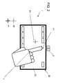
- Fig. 2 shows a potential implementation of a position detection system 1 according to an embodiment of the invention which is coupled to an input device comprising a touch screen.
- the proximity sensor device 3 is installed, for example, proximate the top edge of the touch display surface 22 of the input device 20. However, other installation locations are also possible.
- the input device 20 generates a position signal SP1 indicative of that position P1. It is presumed that the touch screen coordinates output with position signal SP1 are correct and the coordinates of the proximity sensor device 3 output with a corresponding detection signal SD1 can have some offset error (which is then eliminated by calibration).
- the proximity sensor device 3 detects a position D1 which does not correspond to position P1, but is offset by a particular offset value.
- the position signal SP1 output by the input device 20 and corresponding detection signal SD1 output by the proximity sensor device 3 do not correspond.
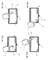
- Fig. 3A-3D show the embodiment according to Fig. 2 in various states of normal operation in which the user is touching the touch display surface at different locations for controlling one or more functions, which is also used for automatically calibrating the proximity sensor device in the background.
- the user's finger F is touching the touch display surface 22 at a position P2 at the top right corner for controlling a function, with the input device 20 generating a position signal SP2 indicative of that position P2.
- the proximity sensor device 3 detects a position D2 which is different from position P2.
- the position signal SP2 output by the input device 20 and corresponding detection signal SD2 output by the proximity sensor device 3 do not correspond.
- the position signal SP2 is provided to the terminal 40 and supplied to the calibration device 4 which calibrates the proximity sensor device 3 with respect to position detection.
- the position signal SP2 and corresponding detection signal SD2 output by the proximity sensor device 3 are corresponding to each other, i.e. are indicating the same position P2 of the detected object with respect to the input device 20.
- the position coordinates of the finger F contained in both signals SP2 and SD2 are the same with respect to a common coordinate system.
- Such common coordinate system may be, for example, a coordinate system of the input device 20.
- the user's finger F is touching the touch display surface 22 at a position P3 at the bottom left corner for controlling a different function as in Fig. 3A , with the input device 20 generating a position signal SP3 indicative of that position P3.
- the proximity sensor device 3 detects a position D3 which is different from position P3.
- the position signal SP3 output by the input device 20 and corresponding detection signal SD3 output by the proximity sensor device 3 do not correspond.
- the position signal SP3 is supplied to the calibration device 4 which again calibrates the proximity sensor device 3 with respect to position detection.
- the position signal SP3 and corresponding detection signal SD3 output by the proximity sensor device 3 are corresponding to each other, i.e. are indicating the same position P3 of the detected object with respect to the input device 20.
- the position coordinates of the finger F contained in both signals SP3 and SD3 are the same with respect to a common coordinate system.
- the user's finger F is touching the touch display surface 22 at a position P4 in some area of the display surface for controlling a different function, with the input device 20 generating a position signal SP4 indicative of that position P4.
- the proximity sensor device 3 detects a position D4 which is different from position P4.
- the position signal SP4 output by the input device 20 and corresponding detection signal SD4 output by the proximity sensor device 3 are different.
- the position signal SP4 is supplied to the calibration device 4 which again calibrates the proximity sensor device 3 with respect to position detection.
- the position signal SP4 and corresponding detection signal SD4 output by the proximity sensor device 3 are corresponding with each other, i.e. are indicating the same position P4 of the detected object with respect to the input device 20.
- the position coordinates of the finger F contained in both signals SP4 and SD4 are the same with respect to a common coordinate system.
- the user's finger F is touching the touch display surface 22 at a position P5 at some area of the display surface for controlling a different function, with the input device 20 generating a position signal SP5 indicative of that position P5.
- the proximity sensor device 3 detects a position D5 which is still different from position P5.
- the signal SP5 output by the input device 20 and corresponding detection signal SD5 output by the proximity sensor device 3 are different.
- the position signal SP5 is supplied to the calibration device 4 which again calibrates the proximity sensor device 3 with respect to position detection.
- the position signal SP5 and corresponding detection signal SD5 output by the proximity sensor device 3 are corresponding with each other, i.e. are indicating the same position P5 of the detected object F with respect to the input device 20.
- the position coordinates of the finger F contained in both signals SP5 and SD5 are the same with respect to a common coordinate system.
- the proximity sensor device 3 is repeatedly calibrated over at least a period of time during normal operation of the input device.
- the proximity sensor device 3 is advantageously calibrated with respect to different locations with respect to the input device 20.
- the calibration device repeatedly receives from the input device 20 position signals SP1 to SPn over a period of time during normal operation of the input device 20.
- Each of the position signals SP1 to SPn contains information regarding a respective position of finger F touching the touch display surface 22.
- the calibration device 4 then each time upon receiving of a respective one of the position signals SP1 to SPn repeatedly calibrates the proximity sensor device 3 with respect to position detection.
- the proximity sensor device 3 is repeatedly calibrated each time when detecting touching of the touch display surface 22 by an object.
- the calibration may be performed continuously over a period of time, which means that calibration is performed continuously upon touching the input device during normal operation over a period of time. Such period of time may be set in advance, and can be modified if required. According to another embodiment, calibration may be performed at intervals, e.g. at certain time intervals, or when receiving particular ones of multiple position signals from the input device, for example at every second received position signal, or at intervals over respective periods of time (such as every day for at least 15 minutes). Such intervals may be set in advance, and can be modified if required. The intervals may also be set depending on environmental influences, such as detected vibrations of a head unit in a vehicle, travelled distance of the vehicle, and/or impacts like accidents. Various implementations are possible in this regard.
- the user is not required to conduct a manually initiated calibration procedure. Rather, the user is touching the input device (e.g., the touch display surface) in normal operation of the input device, which operation is also used for calibration in the background.
- the input device is configured to receive instructions from the user, e.g. for controlling one or more functions of a controlled device, such as one or more functions of a media player, not related to calibration.
- the received instructions are not related to calibration instructions.
- the user is touching elements of a GUI provided on the input device in normal operation thereof to activate one or more functions of the GUI.
- the functions are not related to a calibration procedure. No separate calibration operation is necessary, in which a special calibration procedure different from a GUI in normal operation is displayed on the input device.
- the user is typically touching the input device (e.g., touch screen) many times at many points to activate various functions according to the GUI which are related to normal operation (i.e. not related to calibration). For example, each time the user's finger is actually touching the touch display surface to activate some function in normal operation, e.g. related to controlling a media player, the proximity sensor device is calibrated in the background automatically. Further, the calibration will become better and better over time.
- the calibration is not related to a particular arrangement or design of the GUI. That is, no matter where the user is touching the input device and independent from a particular GUI, a correct calibration is made. For example, proximity sensor coordinates are continuously calibrated every time the user is touching the touch screen. It is not necessary to initialize and perform a manual calibration by the user.
- Fig. 4 shows a flowchart of a method for calibrating a position detection system according to an embodiment of the invention.
- each of the position signals SP1 to SPn contains information indicative of first coordinates x_t, y_t, z_t indicating the location where the respective object F is touching the input device 20, i.e. its touch display surface 22.
- the proximity sensor device 3 outputs the detection signals SD1 to SDn when detecting a position of an object which each contain information indicative of second coordinates of the respective object x_p, y_p, z_p indicating the location where the respective object F is detected by the proximity sensor device 3.
- the first and second coordinates may be in a same or different coordinate systems. If different coordinate systems are used, then a spatial relationship between the coordinate systems should be known which could be used in the calibration.
- step S1 the proximity sensor device 3 initially is tracking an object (here: a user's finger) position according to position coordinates in raw/original values, which are for example x_p0, y_p0, z_p0.
- position coordinates x_p, y_p, z_p are contained in the calibrated output signal of the proximity sensor device 3, such as SD1 to SDn. Initially, i.e. before calibration, the offset values x_offset, y_offset, z_offset used for correction of the detection signal are set to be zero.
- step S3 it is detected whether the touch display surface is touched by an object. If not, then the process returns to step S1. If yes, then in step S4 a respective position signal SP1 to SPn is generated by the input device 20 containing information regarding a respective position of the detected object touching the touch display surface.
- step S4 it is assumed that the output of the input device (e.g., touch screen output) with respect to position of a detected touch is already calibrated and correct.
- step S5 the proximity sensor device 3 is calibrated with respect to detecting the position of the finger F upon receiving of a respective one of the position signals SP1 to SPn, for example each time the calibration device 4 receives one of the position signals SP1 to SPn.
- x_offset, y_offset and z_offset are offset parameters of a detected position of the proximity sensor device 3.
- the calibration device 4 sets the coordinates x_p, y_p, z_p of a proximity sensor detection signal SD1 to SDn to correspond to the coordinates x_t, y_t, z_t received with a corresponding position signal SP1 to SPn. If the coordinates are determined in a common coordinate system, e.g. related to the input device 20, then the coordinates x_p, y_p, z_p may be set to be equal to the coordinates x_t, y_t, z_t.
- a spatial relationship between different coordinate systems should be taken into account as well.
- a respective one of the offset parameters x_offset, y_offset, z_offset is set by calculating a difference between the coordinates x_t, y_t, z_t received with a corresponding position signal SP1 to SPn and respective coordinates x_p, y_p, z_p of the corresponding detection signal.
- step S1 The process then returns to step S1 for repeatedly iterating the steps S1 to S5.
- the determined offset parameters are then used for output of a new proximity sensor detection signal SD1 to SDn with coordinates x_p, y_p, z_p in step S2.
- the proximity sensor device 3 is repeatedly (re-)calibrated with respect to position detection of an object upon receiving of a respective position signal SP1, SP2, SPn from input device 20 according to step S4.
Landscapes
- Engineering & Computer Science (AREA)
- General Engineering & Computer Science (AREA)
- Theoretical Computer Science (AREA)
- Human Computer Interaction (AREA)
- Physics & Mathematics (AREA)
- General Physics & Mathematics (AREA)
- Position Input By Displaying (AREA)
Abstract
Description
- The present invention relates to a position detection system, comprising a proximity sensor device which is configured to detect at least one position of an object approaching towards at least one input device, and a method of calibrating a position detection system comprising a proximity sensor device.
- Object position detection systems known in the art, for example, comprise proximity sensors which detect an approaching of an object to be detected, for example an object of a human such as a human's finger or hand approaching a graphical user interface (GUI) of an automotive input device. For example, when a user's hand approaches the GUI of the input device, such as a human machine interface (HMI) of a head unit in an automobile, a particular function of the head unit may be controlled. For example, when the user's hand is approaching the head unit, a display screen of the head unit may be switched to a particular appearance, such as an enlargement of certain display areas approached by the hand. In this field, there is typically the requirement that the position of the user's finger or hand detected by the position detection system should be quite accurate, so that the user has an intuitive feeling in controlling the respective function.
- Such position detection systems, like 3D finger tracking sensors, are becoming increasingly popular for proximity detection or gesture control. However, in typical implementations, such as in a vehicle, a finger tracking sensor is often an independent system component, which needs to be calibrated to real-world coordinates for correct coordinate output when used in the final system installation. Such a calibration could become necessary several times during lifetime, e.g. after mechanical impact like vehicle vibration which may cause some misalignment.
- A typical calibration process of a finger tracking sensor is initialized and carried out manually. For example, the user needs to start a calibrating procedure which instructs the user to carry out certain movements for calibrating position detection. Potential problems involved with such calibrating procedures may be as follows:
- Some users do not understand the need for calibration. Therefore, they do not see a need to calibrate, and thus will not initiate such calibration procedure. As a consequence, the sensor output may be misaligned and not correct. Further, such calibration is often annoying and feeled like a waste of time, therefore users are not motivated to calibrate the sensor.
- If a calibration (e.g., made at a factory or at initial user setup) has an error, then this error typically remains until the next manual calibration. It may occur that such error is not detected, and then mismatching can continuously happen during normal operation when controlling functions of the input device. Further, the result of a one-time calibration can become invalid during a long period of time of operation by general drifting or some unexpected mechanical impact. This may result in wrong coordinates and needs manual recalibration, which is inappropriate effort for the general user.
-
US 8 504 944 A discloses an image processing apparatus which includes an image display control unit controlling an image display on a display screen, an image generating unit generating a question image including a question and option buttons configured by icons that can be arbitrarily selected for the question, a position detecting unit detecting a position of a pointer present on the display screen from imaging data acquired by imaging the display screen, a position information storing unit storing positions of the icons when the question image is displayed on the display screen, and a control unit specifying an icon out of the icons selected by the pointer based on the position of the pointer and calibrating the position of the pointer based on the position of the icon, which is stored in the position information storing unit, corresponding to the icon specified to have been selected. - It is an object of the present invention to provide a position detection system and a method of calibrating a position detection system which are capable to increase an accuracy of a proximity sensor device.
- According to an aspect of the present invention, there is provided a position detection system, comprising a proximity sensor device which is configured to detect at least one position of an object approaching towards at least one input device, and a calibration device which is configured to calibrate the proximity sensor device with respect to a position detection and comprises a terminal for coupling to the at least one input device. The calibration device is configured to repeatedly receive from the at least one input device position signals over at least a period of time during normal operation of the input device, wherein each of the position signals contains information regarding a respective position of an object touching the at least one input device. The calibration device is configured to repeatedly calibrate the proximity sensor device with respect to position detection upon receiving of a respective one of the position signals.
- For example, the proximity sensor device may be a 3D object tracking sensor. Such sensor is especially useful for pre-touch / proximity function on touch screens in a vehicle. Such sensor may be attached to a touch screen of the at least one input device. For instance, the 3D object tracking sensor coordinates may be continuously calibrated every time the user is touching the touch screen. It is not necessary to initialize and perform a manual calibration by the user.
- In a potential implementation, during normal operation, the user is touching the input device typically many times at many locations, for example to activate some functions in the GUI displayed at the input device. Then, every time the user's finger is actually touching the input device, e.g. the touch display surface, the proximity sensor device may be calibrated by the calibration device in the background automatically. The user is not required to initiate a manual calibration procedure. Moreover, the calibration will become better and better over time during normal operation of the input device, thus increasing accuracy of the proximity sensor device. It is assumed that input devices, such as touch screens, are calibrated in the factory and therefore output correct position coordinates over lifetime.
- According to an embodiment, the proximity sensor device is configured to detect at least one three-dimensional position of an object with respect to the at least one input device.
- According to an embodiment, the proximity sensor device is configured to track a motion of an object approaching towards the at least one input device. Such proximity sensor device is also known as tracking sensor device. For example, the proximity sensor device may be a 3D tracking sensor device for tracking a three-dimensional position and motion of an object.
- For example, the proximity sensor device comprises at least one camera based sensor.
- According to an embodiment, the at least one input device comprises a touch screen, wherein each of the position signals contains information regarding a respective position of an object touching a touch display surface of the touch screen.
- According to an embodiment, the position detection system is configured to be installed in a vehicle. Preferably, the proximity sensor device is configured to be coupled with a head unit of the vehicle comprising the at least one input device.
- According to another aspect, the invention also relates to a vehicle comprising a position detection system as described herein.
- According to a further aspect, there is disclosed herein a method of calibrating a position detection system comprising a proximity sensor device which is configured to detect at least one position of an object approaching towards at least one input device. Particularly, the method comprises the steps of detecting touching of the at least one input device by an object and generating a respective position signal by the at least one input device containing information regarding a position of the respective object touching the at least one input device, receiving from the at least one input device respective position signals repeatedly over at least a period of time during normal operation of the input device, and repeatedly calibrating the proximity sensor device with respect to detecting of at least one position of an object upon receiving of a respective one of the position signals.
- According to an embodiment, the proximity sensor device is repeatedly calibrated each time when detecting touching of the at least one input device by an object.
- According to a further embodiment, the at least one input device comprises a touch screen having a touch display surface, and the step of detecting touching comprises detecting touching of the touch display surface by an object and generating a respective position signal by the at least one input device containing information regarding a position of the respective object touching the touch display surface.
- According to an embodiment, the calibration of the proximity sensor device comprises setting of an offset parameter of a detected position of the proximity sensor device using a corresponding one of the received position signals.
- For example, each of the position signals may contain information indicative of first coordinates of where the respective object is touching the at least one input device, and the proximity sensor device may be configured to output at least one detection signal when detecting a position of an object, the at least one detection signal containing information indicative of second coordinates of the respective detected object. For calibration, the calibration device then sets the second coordinates to correspond to the first coordinates received with a corresponding position signal.
- Further advantages and aspects of the invention will be described with reference to the following Figures, in which:
- Fig. 1
- shows a schematic arrangement of a position detection system according to an embodiment of the invention,
- Fig. 2
- shows a potential implementation of a position detection system according to an embodiment of the invention which is coupled to an input device comprising a touch screen,
- Figs. 3A-3D
- show the embodiment of a position detection system according to
Fig. 2 in various states of normal operation in which the user is touching the touch screen at different locations, - Fig. 4
- shows a flowchart of a method for calibrating a position detection system according to an embodiment of the invention.
-
Fig. 1 shows a schematic arrangement of a position detection system according to an embodiment of the invention. Theposition detection system 1 comprises aproximity sensor device 3 for detecting at least one position of an object (such as a human finger F, or any other object like a pen, etc.) approaching towards aninput device 20. For example, theproximity sensor device 3 detects at least one three-dimensional position of an object with respect to theinput device 20. It may be implemented as a 3D object tracking sensor device which tracks a three-dimensional position and motion of a user's finger approaching theinput device 20. For example, theproximity sensor device 3 comprises at least one camera based sensor. Such camera based sensor has a field of view, as schematically shown inFig. 1 , for monitoring position and/or motion of an object (e.g., finger F) approaching towards theinput device 20. - According to the embodiment as shown in
Fig. 1 , theinput device 20 comprises atouch screen 21 having atouch display surface 22 for displaying a GUI for operation by the user. For example, the user's finger F may touch a particular area on the GUI displayed on thetouch display surface 22 for operation of a particular control function. For instance, when the user's finger F is touching thetouch display surface 22, thetouch screen 21 is configured to generate respective positions signals SP1, SP2, SP3, ..., SPn for a respective touch (which is explained in more detail with respect toFigures 3A-3D ). Each of the position signals SP1 to SPn contains information regarding a respective position of the finger F when touching thetouch display surface 22 of thetouch screen 21. For example, the respective position signal may contain coordinates x, y, z (e.g., z may be z=0) of the respective position with respect to a coordinate system of the input device. - In a particular implementation, the
position detection system 1 is installed in a vehicle. Theproximity sensor device 3 may be coupled with ahead unit 2 of the vehicle which comprises theinput device 20. On thetouch display surface 22, a GUI related to certain functions to be controlled in the vehicle may be displayed. - Upon detection of an object, such as the finger F, the
proximity sensor device 3 produces a respective detection signal SD1, SD2, SD3, ..., SDn, each indicating a respective finger position, for example with respect to a sensor coordinate system or an input device coordinate system. For example, the respective detection signal may contain coordinates x, y, z of the respective detected position with respect to a sensor coordinate system or an input device coordinate system. For example, the detection signals SD1 to SDn may be sent to theinput device 20 which controls, for example, the appearance of particular elements of the GUI shown on the touch display surface accordingly. For example, certain elements of the GUI near the detected finger position may be enlarged. According to another embodiment, a gesture control function may be performed by theinput device 20 if theproximity sensor device 3 is implemented as a tracking sensor device. - The
position detection system 1 further comprises acalibration device 4 for calibrating theproximity sensor device 3 with respect to position detection thereof. Thecalibration device 4 comprises a terminal 40 for coupling to theinput device 20 for receiving the position signals SP1 to SPn. In a particular implementation, thecalibration device 4 may be a component, such as a microprocessor, which may be contained in theproximity sensor device 3. According to another embodiment, thecalibration device 4 may be a separate component installed externally from thesensor device 3, or may be a component of theinput device 20 and/or of thehead unit 2. With calibration of theproximity sensor device 3, thecalibration device 4 adjusts generation of a respective detection signal SD1 to SDn indicative of a detected position of an object to coincide or correspond with a corresponding position signal SP1 to SPn received from theinput device 20 when the object is touching the input device, as explained in more detail below. More particularly, after the calibration, the position coordinates contained in a generated detection signal SD1 to SDn coincide or correspond with respective position coordinates of a corresponding position signal SP1 to SPn. - For example, the
sensor device 3 needs to be calibrated to real-world coordinates, so that when the user is touching thetouch display surface 22, the sensor coordinates and the touch screen coordinates are corresponding to each other or even identical. -
Fig. 2 shows a potential implementation of aposition detection system 1 according to an embodiment of the invention which is coupled to an input device comprising a touch screen. - Referring to
Fig. 2 , theproximity sensor device 3 is installed, for example, proximate the top edge of thetouch display surface 22 of theinput device 20. However, other installation locations are also possible. Once the user is touching with finger F thetouch display surface 22 at any position, such as position P1 shown inFig. 2 , theinput device 20 generates a position signal SP1 indicative of that position P1. It is presumed that the touch screen coordinates output with position signal SP1 are correct and the coordinates of theproximity sensor device 3 output with a corresponding detection signal SD1 can have some offset error (which is then eliminated by calibration). In an exemplary scenario, as shown inFig. 2 , when theinput device 20 detects a position P1 when the finger F is touching thetouch display surface 22, theproximity sensor device 3 detects a position D1 which does not correspond to position P1, but is offset by a particular offset value. Thus, the position signal SP1 output by theinput device 20 and corresponding detection signal SD1 output by theproximity sensor device 3 do not correspond. -
Fig. 3A-3D show the embodiment according toFig. 2 in various states of normal operation in which the user is touching the touch display surface at different locations for controlling one or more functions, which is also used for automatically calibrating the proximity sensor device in the background. - According to
Fig. 3A , the user's finger F is touching thetouch display surface 22 at a position P2 at the top right corner for controlling a function, with theinput device 20 generating a position signal SP2 indicative of that position P2. In the exemplary scenario as shown inFig. 3A , when theinput device 20 detects a position P2 when the finger F is touching thetouch display surface 22, theproximity sensor device 3 detects a position D2 which is different from position P2. Thus, the position signal SP2 output by theinput device 20 and corresponding detection signal SD2 output by theproximity sensor device 3 do not correspond. The position signal SP2 is provided to the terminal 40 and supplied to thecalibration device 4 which calibrates theproximity sensor device 3 with respect to position detection. After the calibration, the position signal SP2 and corresponding detection signal SD2 output by theproximity sensor device 3 are corresponding to each other, i.e. are indicating the same position P2 of the detected object with respect to theinput device 20. For example, the position coordinates of the finger F contained in both signals SP2 and SD2 are the same with respect to a common coordinate system. Such common coordinate system may be, for example, a coordinate system of theinput device 20. - According to
Fig. 3B , the user's finger F is touching thetouch display surface 22 at a position P3 at the bottom left corner for controlling a different function as inFig. 3A , with theinput device 20 generating a position signal SP3 indicative of that position P3. In the exemplary scenario ofFig. 3B , when theinput device 20 detects the position P3 upon touching thetouch display surface 22, theproximity sensor device 3 detects a position D3 which is different from position P3. Thus, the position signal SP3 output by theinput device 20 and corresponding detection signal SD3 output by theproximity sensor device 3 do not correspond. The position signal SP3 is supplied to thecalibration device 4 which again calibrates theproximity sensor device 3 with respect to position detection. After the calibration, the position signal SP3 and corresponding detection signal SD3 output by theproximity sensor device 3 are corresponding to each other, i.e. are indicating the same position P3 of the detected object with respect to theinput device 20. For example, the position coordinates of the finger F contained in both signals SP3 and SD3 are the same with respect to a common coordinate system. - According to
Fig. 3C , the user's finger F is touching thetouch display surface 22 at a position P4 in some area of the display surface for controlling a different function, with theinput device 20 generating a position signal SP4 indicative of that position P4. In the exemplary scenario as shown inFig. 3C , when theinput device 20 detects position P4 when the finger F is touching thetouch display surface 22, theproximity sensor device 3 detects a position D4 which is different from position P4. Thus, the position signal SP4 output by theinput device 20 and corresponding detection signal SD4 output by theproximity sensor device 3 are different. The position signal SP4 is supplied to thecalibration device 4 which again calibrates theproximity sensor device 3 with respect to position detection. After the calibration, the position signal SP4 and corresponding detection signal SD4 output by theproximity sensor device 3 are corresponding with each other, i.e. are indicating the same position P4 of the detected object with respect to theinput device 20. For example, the position coordinates of the finger F contained in both signals SP4 and SD4 are the same with respect to a common coordinate system. - According to
Fig. 3D , the user's finger F is touching thetouch display surface 22 at a position P5 at some area of the display surface for controlling a different function, with theinput device 20 generating a position signal SP5 indicative of that position P5. In the scenario ofFig. 3D , when theinput device 20 detects the position P5 upon touching thetouch display surface 22, theproximity sensor device 3 detects a position D5 which is still different from position P5. Thus, the signal SP5 output by theinput device 20 and corresponding detection signal SD5 output by theproximity sensor device 3 are different. The position signal SP5 is supplied to thecalibration device 4 which again calibrates theproximity sensor device 3 with respect to position detection. After the calibration, the position signal SP5 and corresponding detection signal SD5 output by theproximity sensor device 3 are corresponding with each other, i.e. are indicating the same position P5 of the detected object F with respect to theinput device 20. For example, the position coordinates of the finger F contained in both signals SP5 and SD5 are the same with respect to a common coordinate system. - In this way, the
proximity sensor device 3 is repeatedly calibrated over at least a period of time during normal operation of the input device. By touching different locations at the input device, theproximity sensor device 3 is advantageously calibrated with respect to different locations with respect to theinput device 20. Particularly, the calibration device repeatedly receives from theinput device 20 position signals SP1 to SPn over a period of time during normal operation of theinput device 20. Each of the position signals SP1 to SPn contains information regarding a respective position of finger F touching thetouch display surface 22. Thecalibration device 4 then each time upon receiving of a respective one of the position signals SP1 to SPn repeatedly calibrates theproximity sensor device 3 with respect to position detection. For example, theproximity sensor device 3 is repeatedly calibrated each time when detecting touching of thetouch display surface 22 by an object. - The calibration may be performed continuously over a period of time, which means that calibration is performed continuously upon touching the input device during normal operation over a period of time. Such period of time may be set in advance, and can be modified if required. According to another embodiment, calibration may be performed at intervals, e.g. at certain time intervals, or when receiving particular ones of multiple position signals from the input device, for example at every second received position signal, or at intervals over respective periods of time (such as every day for at least 15 minutes). Such intervals may be set in advance, and can be modified if required. The intervals may also be set depending on environmental influences, such as detected vibrations of a head unit in a vehicle, travelled distance of the vehicle, and/or impacts like accidents. Various implementations are possible in this regard.
- Preferably, the user is not required to conduct a manually initiated calibration procedure. Rather, the user is touching the input device (e.g., the touch display surface) in normal operation of the input device, which operation is also used for calibration in the background. In normal operation, the input device is configured to receive instructions from the user, e.g. for controlling one or more functions of a controlled device, such as one or more functions of a media player, not related to calibration. Particularly, the received instructions are not related to calibration instructions. For example, the user is touching elements of a GUI provided on the input device in normal operation thereof to activate one or more functions of the GUI. The functions are not related to a calibration procedure. No separate calibration operation is necessary, in which a special calibration procedure different from a GUI in normal operation is displayed on the input device. During normal operation, the user is typically touching the input device (e.g., touch screen) many times at many points to activate various functions according to the GUI which are related to normal operation (i.e. not related to calibration). For example, each time the user's finger is actually touching the touch display surface to activate some function in normal operation, e.g. related to controlling a media player, the proximity sensor device is calibrated in the background automatically. Further, the calibration will become better and better over time. The calibration is not related to a particular arrangement or design of the GUI. That is, no matter where the user is touching the input device and independent from a particular GUI, a correct calibration is made. For example, proximity sensor coordinates are continuously calibrated every time the user is touching the touch screen. It is not necessary to initialize and perform a manual calibration by the user.
-
Fig. 4 shows a flowchart of a method for calibrating a position detection system according to an embodiment of the invention. - Basically, according to the following embodiment, each of the position signals SP1 to SPn contains information indicative of first coordinates x_t, y_t, z_t indicating the location where the respective object F is touching the
input device 20, i.e. itstouch display surface 22. Theproximity sensor device 3 outputs the detection signals SD1 to SDn when detecting a position of an object which each contain information indicative of second coordinates of the respective object x_p, y_p, z_p indicating the location where the respective object F is detected by theproximity sensor device 3. The first and second coordinates may be in a same or different coordinate systems. If different coordinate systems are used, then a spatial relationship between the coordinate systems should be known which could be used in the calibration. - In step S1, the
proximity sensor device 3 initially is tracking an object (here: a user's finger) position according to position coordinates in raw/original values, which are for example x_p0, y_p0, z_p0. In step S2, theproximity sensor device 3 outputs detected object position coordinates with corrected/calibrated values as a result of a preceding calibration procedure:


- These position coordinates x_p, y_p, z_p are contained in the calibrated output signal of the
proximity sensor device 3, such as SD1 to SDn. Initially, i.e. before calibration, the offset values x_offset, y_offset, z_offset used for correction of the detection signal are set to be zero. - In step S3, it is detected whether the touch display surface is touched by an object. If not, then the process returns to step S1. If yes, then in step S4 a respective position signal SP1 to SPn is generated by the
input device 20 containing information regarding a respective position of the detected object touching the touch display surface. For example, each of the position signals SP1 to SPn is containing the position coordinates x_t, y_t and z_t, wherein z_t may be set as z_t = 0 in a coordinate system of the input device as the detected z-position is the position of the touch display surface. For step S4, it is assumed that the output of the input device (e.g., touch screen output) with respect to position of a detected touch is already calibrated and correct. - In step S5, the
proximity sensor device 3 is calibrated with respect to detecting the position of the finger F upon receiving of a respective one of the position signals SP1 to SPn, for example each time thecalibration device 4 receives one of the position signals SP1 to SPn. (Re-)Calibration of the proximity sensor device may be made, for example, as follows:


- wherein x_offset, y_offset and z_offset are offset parameters of a detected position of the
proximity sensor device 3. With determining the respective offset parameters, thecalibration device 4 sets the coordinates x_p, y_p, z_p of a proximity sensor detection signal SD1 to SDn to correspond to the coordinates x_t, y_t, z_t received with a corresponding position signal SP1 to SPn. If the coordinates are determined in a common coordinate system, e.g. related to theinput device 20, then the coordinates x_p, y_p, z_p may be set to be equal to the coordinates x_t, y_t, z_t. Otherwise, a spatial relationship between different coordinate systems should be taken into account as well. With calibration of the proximity sensor device 3 a respective one of the offset parameters x_offset, y_offset, z_offset is set by calculating a difference between the coordinates x_t, y_t, z_t received with a corresponding position signal SP1 to SPn and respective coordinates x_p, y_p, z_p of the corresponding detection signal. - For step S5, it is assumed that in the moment of touching the touch display surface, z_t = 0 (i.e. finger distance to the touch display surface is zero), therefore z_offset = z_t - z_p0 is the same as z_offset = -z_p0.
- The process then returns to step S1 for repeatedly iterating the steps S1 to S5. The determined offset parameters are then used for output of a new proximity sensor detection signal SD1 to SDn with coordinates x_p, y_p, z_p in step S2. In this way, the
proximity sensor device 3 is repeatedly (re-)calibrated with respect to position detection of an object upon receiving of a respective position signal SP1, SP2, SPn frominput device 20 according to step S4.
Claims (14)
- A position detection system (1), comprising:- a proximity sensor device (3) which is configured to detect at least one position of an object (F) approaching towards at least one input device (20),- a calibration device (4) which is configured to calibrate the proximity sensor device (3) with respect to a position detection and comprises a terminal (40) for coupling to the at least one input device (20),- wherein the calibration device (4) is configured to repeatedly receive from the at least one input device (20) position signals (SP1, SP2, SPn) over at least a period of time during normal operation of the input device (20),- wherein each of the position signals (SP1, SP2, SPn) contains information regarding a respective position of an object (F) touching the at least one input device (20),- wherein the calibration device (4) is configured to repeatedly calibrate the proximity sensor device (3) with respect to position detection upon receiving of a respective one of the position signals (SP1, SP2, SPn).
- The position detection system according to claim 1, wherein the proximity sensor device (3) is configured to detect at least one three-dimensional position of an object (F) with respect to the at least one input device (20).
- The position detection system according to claim 1 or 2, wherein the proximity sensor device (3) is configured to track a motion of an object (F) approaching towards the at least one input device (20).
- The position detection system according to any of claims 1 to 3, wherein the proximity sensor device (3) comprises at least one camera based sensor.
- The position detection system according to any of claims 1 to 4, wherein the terminal (40) is for coupling to the at least one input device (20) which comprises a touch screen (21), wherein each of the position signals (SP1, SP2, SPn) contains information regarding a respective position of an object (F) touching a touch display surface (22) of the touch screen (21).
- The position detection system according to any of claims 1 to 6,- wherein each of the position signals (SP1, SP2, SPn) contains information indicative of first coordinates (x_t, y_t, z_t) of where the respective object (F) is touching the at least one input device (20),- wherein the proximity sensor device (3) is configured to output at least one detection signal (SD1, SD2, SDn) when detecting a position of an object (F), the at least one detection signal (SD1, SD2, SDn) containing information indicative of second coordinates of the respective object (x_p, y_p, z_p),- wherein the calibration device (4) is configured to set the second coordinates (x_p, y_p, z_p) to correspond to the first coordinates (x_t, y_t, z_t) received with a corresponding position signal (SP1, SP2, SPn).
- The position detection system according to any of claims 1 to 6, wherein the position detection system (1) is configured to be installed in a vehicle.
- The position detection system according to claim 7, wherein the proximity sensor device (3) is configured to be coupled with a head unit (2) of the vehicle comprising the at least one input device (20).
- A vehicle comprising a position detection system (1) according to any of the preceding claims.
- A method of calibrating a position detection system (1) comprising a proximity sensor device (3) which is configured to detect at least one position of an object (F) approaching towards at least one input device (20), the method comprising:- detecting touching of the at least one input device (20) by an object (F) and generating a respective position signal (SP1, SP2, SPn) by the at least one input device (20) containing information regarding a position of the respective object (F) touching the at least one input device (20),- receiving from the at least one input device (20) respective position signals (SP1, SP2, SPn) repeatedly over at least a period of time during normal operation of the input device (20),- repeatedly calibrating the proximity sensor device (3) with respect to detecting of at least one position of an object (F) upon receiving of a respective one of the position signals (SP1, SP2, SPn).
- The method according to claim 10, wherein the proximity sensor device (3) is repeatedly calibrated each time when detecting touching of the at least one input device (20) by an object (F).
- The method according to one of claims 10 or 11, wherein the at least one input device (20) comprises a touch screen (21) having a touch display surface (22), and the step of detecting touching comprises detecting touching of the touch display surface (22) by an object (F) and generating a respective position signal (SP1, SP2, SPn) by the at least one input device (20) containing information regarding a position of the respective object (F) touching the touch display surface (22).
- The method according to one of claims 10 to 12, wherein the calibration of the proximity sensor device (3) comprises setting of an offset parameter (x_offset, y_offset, z_offset) of a detected position detected by the proximity sensor device (3) using a corresponding one of the received position signals (SP1, SP2, SPn).
- The method according to one of claims 10 to 13,- wherein each of the position signals (SP1, SP2, SPn) contains information indicative of first coordinates (x_t, y_t, z_t) of where the respective object (F) is touching the at least one input device (20),- wherein the proximity sensor device (3) is configured to output at least one detection signal (SD1, SD2, SDn) when detecting a position of an object (F), the at least one detection signal (SD1, SD2, SDn) containing information indicative of second coordinates of the respective object (x_p, y_p, z_p),- wherein the calibration of the proximity sensor device (3) comprises setting of an offset parameter (x_offset, y_offset, z_offset) of a detected position detected by the proximity sensor device (3) by calculating a difference between the first coordinates (x_t, y_t, z_t) received with a corresponding position signal (SP1, SP2, SPn) and respective second coordinates (x_p, y_p, z_p) of the at least one detection signal (SD1, SD2, SDn).
Priority Applications (1)
| Application Number | Priority Date | Filing Date | Title |
|---|---|---|---|
| EP14002804.4A EP2985678B1 (en) | 2014-08-11 | 2014-08-11 | Position detection system and method of calibrating a position detection system |
Applications Claiming Priority (1)
| Application Number | Priority Date | Filing Date | Title |
|---|---|---|---|
| EP14002804.4A EP2985678B1 (en) | 2014-08-11 | 2014-08-11 | Position detection system and method of calibrating a position detection system |
Publications (2)
| Publication Number | Publication Date |
|---|---|
| EP2985678A1 true EP2985678A1 (en) | 2016-02-17 |
| EP2985678B1 EP2985678B1 (en) | 2019-04-24 |
Family
ID=51357700
Family Applications (1)
| Application Number | Title | Priority Date | Filing Date |
|---|---|---|---|
| EP14002804.4A Not-in-force EP2985678B1 (en) | 2014-08-11 | 2014-08-11 | Position detection system and method of calibrating a position detection system |
Country Status (1)
| Country | Link |
|---|---|
| EP (1) | EP2985678B1 (en) |
Cited By (1)
| Publication number | Priority date | Publication date | Assignee | Title |
|---|---|---|---|---|
| US20240061529A1 (en) * | 2022-08-22 | 2024-02-22 | Hyundai Mobis Co., Ltd. | Method and apparatus for detecting object position using sensor |
Families Citing this family (1)
| Publication number | Priority date | Publication date | Assignee | Title |
|---|---|---|---|---|
| WO2023158166A1 (en) * | 2022-02-21 | 2023-08-24 | 삼성전자 주식회사 | Electronic device and operation method thereof |
Citations (5)
| Publication number | Priority date | Publication date | Assignee | Title |
|---|---|---|---|---|
| US20040201575A1 (en) * | 2003-04-08 | 2004-10-14 | Morrison Gerald D. | Auto-aligning touch system and method |
| US20050248539A1 (en) * | 2004-05-05 | 2005-11-10 | Morrison Gerald D | Apparatus and method for detecting a pointer relative to a touch surface |
| US20130147833A1 (en) * | 2011-12-09 | 2013-06-13 | Ident Technology Ag | Electronic Device with a User Interface that has more than Two Degrees of Freedom, the User Interface Comprising a Touch-Sensitive Surface and Contact-Free Detection Means |
| US8504944B2 (en) | 2010-03-30 | 2013-08-06 | Sony Corporation | Image processing apparatus, method of displaying image, image display program, and recording medium having image display program for displaying image recorded thereon |
| US20140025263A1 (en) * | 2011-02-19 | 2014-01-23 | Volkswagen Ag | Method and Device for Providing a User Interface, in Particular in a Vehicle |
-
2014
- 2014-08-11 EP EP14002804.4A patent/EP2985678B1/en not_active Not-in-force
Patent Citations (5)
| Publication number | Priority date | Publication date | Assignee | Title |
|---|---|---|---|---|
| US20040201575A1 (en) * | 2003-04-08 | 2004-10-14 | Morrison Gerald D. | Auto-aligning touch system and method |
| US20050248539A1 (en) * | 2004-05-05 | 2005-11-10 | Morrison Gerald D | Apparatus and method for detecting a pointer relative to a touch surface |
| US8504944B2 (en) | 2010-03-30 | 2013-08-06 | Sony Corporation | Image processing apparatus, method of displaying image, image display program, and recording medium having image display program for displaying image recorded thereon |
| US20140025263A1 (en) * | 2011-02-19 | 2014-01-23 | Volkswagen Ag | Method and Device for Providing a User Interface, in Particular in a Vehicle |
| US20130147833A1 (en) * | 2011-12-09 | 2013-06-13 | Ident Technology Ag | Electronic Device with a User Interface that has more than Two Degrees of Freedom, the User Interface Comprising a Touch-Sensitive Surface and Contact-Free Detection Means |
Cited By (2)
| Publication number | Priority date | Publication date | Assignee | Title |
|---|---|---|---|---|
| US20240061529A1 (en) * | 2022-08-22 | 2024-02-22 | Hyundai Mobis Co., Ltd. | Method and apparatus for detecting object position using sensor |
| US12039135B2 (en) * | 2022-08-22 | 2024-07-16 | Hyundai Mobis Co., Ltd. | Method and apparatus for detecting object position using sensor |
Also Published As
| Publication number | Publication date |
|---|---|
| EP2985678B1 (en) | 2019-04-24 |
Similar Documents
| Publication | Publication Date | Title |
|---|---|---|
| JP5261554B2 (en) | Human-machine interface for vehicles based on fingertip pointing and gestures | |
| US9007345B2 (en) | Method and apparatus for displaying an object | |
| EP2375381B1 (en) | Image processing apparatus | |
| US10019155B2 (en) | Touch control panel for vehicle control system | |
| CN106030460A (en) | Gesture guidance device for mobile body, gesture guidance system for mobile body, and gesture guidance method for mobile body | |
| US20160004424A1 (en) | Touch panel operation device and operation event determination method in touch panel operation device | |
| US20160162092A1 (en) | Operation device | |
| EP2985678A1 (en) | Position detection system and method of calibrating a position detection system | |
| CN105912101B (en) | Projection control method and electronic equipment | |
| US9483173B2 (en) | Information processor input button display that prevents selection of undesired button | |
| US10949023B2 (en) | Touch panel device, touch panel device control method, program, and storage medium storing the program | |
| KR101637285B1 (en) | Control panel for providing shortcut function | |
| US20200142528A1 (en) | Display control apparatus and control method for the display control apparatus | |
| JP5772804B2 (en) | Operation device and operation teaching method for operation device | |
| KR101573287B1 (en) | TOUCH POSITION DISPLAY METHOD AND APPARATUS IN ELECT | |
| US10271002B2 (en) | Image display apparatus, external device, image display method, and image display system | |
| JP6525504B2 (en) | Input device and operation input method | |
| US20170192659A1 (en) | Remote Touch Sensitive Monitoring System, Monitored Apparatus, Monitoring Apparatus and Controlling Method Thereof | |
| AU2019411655B2 (en) | Method and controller for setting up traffic monitoring for a monitoring location, and system for carrying out traffic monitoring for a monitoring location | |
| JP6538895B2 (en) | Touch panel device and touch panel display system | |
| JP6282919B2 (en) | Touch panel integrated display device | |
| JP2015194887A (en) | Input device, main device, input information correction system, control program | |
| EP4186231A1 (en) | System for augmented reality | |
| EP4302168A1 (en) | A computer a software module arrangement, a circuitry arrangement, a user equipment and a method for an improved and extended user interface | |
| JPH04321120A (en) | Touch screen controller |
Legal Events
| Date | Code | Title | Description |
|---|---|---|---|
| PUAI | Public reference made under article 153(3) epc to a published international application that has entered the european phase |
Free format text: ORIGINAL CODE: 0009012 |
|
| AK | Designated contracting states |
Kind code of ref document: A1 Designated state(s): AL AT BE BG CH CY CZ DE DK EE ES FI FR GB GR HR HU IE IS IT LI LT LU LV MC MK MT NL NO PL PT RO RS SE SI SK SM TR |
|
| AX | Request for extension of the european patent |
Extension state: BA ME |
|
| 17P | Request for examination filed |
Effective date: 20160107 |
|
| RBV | Designated contracting states (corrected) |
Designated state(s): AL AT BE BG CH CY CZ DE DK EE ES FI FR GB GR HR HU IE IS IT LI LT LU LV MC MK MT NL NO PL PT RO RS SE SI SK SM TR |
|
| STAA | Information on the status of an ep patent application or granted ep patent |
Free format text: STATUS: EXAMINATION IS IN PROGRESS |
|
| 17Q | First examination report despatched |
Effective date: 20180516 |
|
| REG | Reference to a national code |
Ref country code: DE Ref legal event code: R079 Ref document number: 602014045166 Country of ref document: DE Free format text: PREVIOUS MAIN CLASS: G06F0003041000 Ipc: G06F0003030000 |
|
| GRAP | Despatch of communication of intention to grant a patent |
Free format text: ORIGINAL CODE: EPIDOSNIGR1 |
|
| STAA | Information on the status of an ep patent application or granted ep patent |
Free format text: STATUS: GRANT OF PATENT IS INTENDED |
|
| RIC1 | Information provided on ipc code assigned before grant |
Ipc: G06F 3/03 20060101AFI20181022BHEP Ipc: G06F 3/01 20060101ALI20181022BHEP Ipc: G06F 3/041 20060101ALI20181022BHEP |
|
| INTG | Intention to grant announced |
Effective date: 20181126 |
|
| GRAS | Grant fee paid |
Free format text: ORIGINAL CODE: EPIDOSNIGR3 |
|
| GRAA | (expected) grant |
Free format text: ORIGINAL CODE: 0009210 |
|
| STAA | Information on the status of an ep patent application or granted ep patent |
Free format text: STATUS: THE PATENT HAS BEEN GRANTED |
|
| AK | Designated contracting states |
Kind code of ref document: B1 Designated state(s): AL AT BE BG CH CY CZ DE DK EE ES FI FR GB GR HR HU IE IS IT LI LT LU LV MC MK MT NL NO PL PT RO RS SE SI SK SM TR |
|
| REG | Reference to a national code |
Ref country code: GB Ref legal event code: FG4D |
|
| REG | Reference to a national code |
Ref country code: CH Ref legal event code: EP |
|
| REG | Reference to a national code |
Ref country code: AT Ref legal event code: REF Ref document number: 1124898 Country of ref document: AT Kind code of ref document: T Effective date: 20190515 Ref country code: IE Ref legal event code: FG4D |
|
| REG | Reference to a national code |
Ref country code: DE Ref legal event code: R096 Ref document number: 602014045166 Country of ref document: DE |
|
| REG | Reference to a national code |
Ref country code: NL Ref legal event code: MP Effective date: 20190424 |
|
| REG | Reference to a national code |
Ref country code: LT Ref legal event code: MG4D |
|
| PG25 | Lapsed in a contracting state [announced via postgrant information from national office to epo] |
Ref country code: NL Free format text: LAPSE BECAUSE OF FAILURE TO SUBMIT A TRANSLATION OF THE DESCRIPTION OR TO PAY THE FEE WITHIN THE PRESCRIBED TIME-LIMIT Effective date: 20190424 |
|
| PG25 | Lapsed in a contracting state [announced via postgrant information from national office to epo] |
Ref country code: FI Free format text: LAPSE BECAUSE OF FAILURE TO SUBMIT A TRANSLATION OF THE DESCRIPTION OR TO PAY THE FEE WITHIN THE PRESCRIBED TIME-LIMIT Effective date: 20190424 Ref country code: NO Free format text: LAPSE BECAUSE OF FAILURE TO SUBMIT A TRANSLATION OF THE DESCRIPTION OR TO PAY THE FEE WITHIN THE PRESCRIBED TIME-LIMIT Effective date: 20190724 Ref country code: LT Free format text: LAPSE BECAUSE OF FAILURE TO SUBMIT A TRANSLATION OF THE DESCRIPTION OR TO PAY THE FEE WITHIN THE PRESCRIBED TIME-LIMIT Effective date: 20190424 Ref country code: HR Free format text: LAPSE BECAUSE OF FAILURE TO SUBMIT A TRANSLATION OF THE DESCRIPTION OR TO PAY THE FEE WITHIN THE PRESCRIBED TIME-LIMIT Effective date: 20190424 Ref country code: ES Free format text: LAPSE BECAUSE OF FAILURE TO SUBMIT A TRANSLATION OF THE DESCRIPTION OR TO PAY THE FEE WITHIN THE PRESCRIBED TIME-LIMIT Effective date: 20190424 Ref country code: SE Free format text: LAPSE BECAUSE OF FAILURE TO SUBMIT A TRANSLATION OF THE DESCRIPTION OR TO PAY THE FEE WITHIN THE PRESCRIBED TIME-LIMIT Effective date: 20190424 Ref country code: PT Free format text: LAPSE BECAUSE OF FAILURE TO SUBMIT A TRANSLATION OF THE DESCRIPTION OR TO PAY THE FEE WITHIN THE PRESCRIBED TIME-LIMIT Effective date: 20190824 Ref country code: AL Free format text: LAPSE BECAUSE OF FAILURE TO SUBMIT A TRANSLATION OF THE DESCRIPTION OR TO PAY THE FEE WITHIN THE PRESCRIBED TIME-LIMIT Effective date: 20190424 |
|
| PG25 | Lapsed in a contracting state [announced via postgrant information from national office to epo] |
Ref country code: LV Free format text: LAPSE BECAUSE OF FAILURE TO SUBMIT A TRANSLATION OF THE DESCRIPTION OR TO PAY THE FEE WITHIN THE PRESCRIBED TIME-LIMIT Effective date: 20190424 Ref country code: RS Free format text: LAPSE BECAUSE OF FAILURE TO SUBMIT A TRANSLATION OF THE DESCRIPTION OR TO PAY THE FEE WITHIN THE PRESCRIBED TIME-LIMIT Effective date: 20190424 Ref country code: GR Free format text: LAPSE BECAUSE OF FAILURE TO SUBMIT A TRANSLATION OF THE DESCRIPTION OR TO PAY THE FEE WITHIN THE PRESCRIBED TIME-LIMIT Effective date: 20190725 Ref country code: PL Free format text: LAPSE BECAUSE OF FAILURE TO SUBMIT A TRANSLATION OF THE DESCRIPTION OR TO PAY THE FEE WITHIN THE PRESCRIBED TIME-LIMIT Effective date: 20190424 Ref country code: BG Free format text: LAPSE BECAUSE OF FAILURE TO SUBMIT A TRANSLATION OF THE DESCRIPTION OR TO PAY THE FEE WITHIN THE PRESCRIBED TIME-LIMIT Effective date: 20190724 |
|
| REG | Reference to a national code |
Ref country code: AT Ref legal event code: MK05 Ref document number: 1124898 Country of ref document: AT Kind code of ref document: T Effective date: 20190424 |
|
| PG25 | Lapsed in a contracting state [announced via postgrant information from national office to epo] |
Ref country code: IS Free format text: LAPSE BECAUSE OF FAILURE TO SUBMIT A TRANSLATION OF THE DESCRIPTION OR TO PAY THE FEE WITHIN THE PRESCRIBED TIME-LIMIT Effective date: 20190824 |
|
| REG | Reference to a national code |
Ref country code: DE Ref legal event code: R097 Ref document number: 602014045166 Country of ref document: DE |
|
| PG25 | Lapsed in a contracting state [announced via postgrant information from national office to epo] |
Ref country code: RO Free format text: LAPSE BECAUSE OF FAILURE TO SUBMIT A TRANSLATION OF THE DESCRIPTION OR TO PAY THE FEE WITHIN THE PRESCRIBED TIME-LIMIT Effective date: 20190424 Ref country code: CZ Free format text: LAPSE BECAUSE OF FAILURE TO SUBMIT A TRANSLATION OF THE DESCRIPTION OR TO PAY THE FEE WITHIN THE PRESCRIBED TIME-LIMIT Effective date: 20190424 Ref country code: SK Free format text: LAPSE BECAUSE OF FAILURE TO SUBMIT A TRANSLATION OF THE DESCRIPTION OR TO PAY THE FEE WITHIN THE PRESCRIBED TIME-LIMIT Effective date: 20190424 Ref country code: DK Free format text: LAPSE BECAUSE OF FAILURE TO SUBMIT A TRANSLATION OF THE DESCRIPTION OR TO PAY THE FEE WITHIN THE PRESCRIBED TIME-LIMIT Effective date: 20190424 Ref country code: AT Free format text: LAPSE BECAUSE OF FAILURE TO SUBMIT A TRANSLATION OF THE DESCRIPTION OR TO PAY THE FEE WITHIN THE PRESCRIBED TIME-LIMIT Effective date: 20190424 Ref country code: EE Free format text: LAPSE BECAUSE OF FAILURE TO SUBMIT A TRANSLATION OF THE DESCRIPTION OR TO PAY THE FEE WITHIN THE PRESCRIBED TIME-LIMIT Effective date: 20190424 |
|
| PG25 | Lapsed in a contracting state [announced via postgrant information from national office to epo] |
Ref country code: SM Free format text: LAPSE BECAUSE OF FAILURE TO SUBMIT A TRANSLATION OF THE DESCRIPTION OR TO PAY THE FEE WITHIN THE PRESCRIBED TIME-LIMIT Effective date: 20190424 Ref country code: IT Free format text: LAPSE BECAUSE OF FAILURE TO SUBMIT A TRANSLATION OF THE DESCRIPTION OR TO PAY THE FEE WITHIN THE PRESCRIBED TIME-LIMIT Effective date: 20190424 |
|
| PLBE | No opposition filed within time limit |
Free format text: ORIGINAL CODE: 0009261 |
|
| STAA | Information on the status of an ep patent application or granted ep patent |
Free format text: STATUS: NO OPPOSITION FILED WITHIN TIME LIMIT |
|
| PG25 | Lapsed in a contracting state [announced via postgrant information from national office to epo] |
Ref country code: TR Free format text: LAPSE BECAUSE OF FAILURE TO SUBMIT A TRANSLATION OF THE DESCRIPTION OR TO PAY THE FEE WITHIN THE PRESCRIBED TIME-LIMIT Effective date: 20190424 |
|
| 26N | No opposition filed |
Effective date: 20200127 |
|
| PG25 | Lapsed in a contracting state [announced via postgrant information from national office to epo] |
Ref country code: SI Free format text: LAPSE BECAUSE OF FAILURE TO SUBMIT A TRANSLATION OF THE DESCRIPTION OR TO PAY THE FEE WITHIN THE PRESCRIBED TIME-LIMIT Effective date: 20190424 Ref country code: LU Free format text: LAPSE BECAUSE OF NON-PAYMENT OF DUE FEES Effective date: 20190811 Ref country code: LI Free format text: LAPSE BECAUSE OF NON-PAYMENT OF DUE FEES Effective date: 20190831 Ref country code: CH Free format text: LAPSE BECAUSE OF NON-PAYMENT OF DUE FEES Effective date: 20190831 Ref country code: MC Free format text: LAPSE BECAUSE OF FAILURE TO SUBMIT A TRANSLATION OF THE DESCRIPTION OR TO PAY THE FEE WITHIN THE PRESCRIBED TIME-LIMIT Effective date: 20190424 |
|
| REG | Reference to a national code |
Ref country code: BE Ref legal event code: MM Effective date: 20190831 |
|
| PG25 | Lapsed in a contracting state [announced via postgrant information from national office to epo] |
Ref country code: IE Free format text: LAPSE BECAUSE OF NON-PAYMENT OF DUE FEES Effective date: 20190811 |
|
| PG25 | Lapsed in a contracting state [announced via postgrant information from national office to epo] |
Ref country code: BE Free format text: LAPSE BECAUSE OF NON-PAYMENT OF DUE FEES Effective date: 20190831 |
|
| PG25 | Lapsed in a contracting state [announced via postgrant information from national office to epo] |
Ref country code: CY Free format text: LAPSE BECAUSE OF FAILURE TO SUBMIT A TRANSLATION OF THE DESCRIPTION OR TO PAY THE FEE WITHIN THE PRESCRIBED TIME-LIMIT Effective date: 20190424 |
|
| PG25 | Lapsed in a contracting state [announced via postgrant information from national office to epo] |
Ref country code: MT Free format text: LAPSE BECAUSE OF FAILURE TO SUBMIT A TRANSLATION OF THE DESCRIPTION OR TO PAY THE FEE WITHIN THE PRESCRIBED TIME-LIMIT Effective date: 20190424 Ref country code: HU Free format text: LAPSE BECAUSE OF FAILURE TO SUBMIT A TRANSLATION OF THE DESCRIPTION OR TO PAY THE FEE WITHIN THE PRESCRIBED TIME-LIMIT; INVALID AB INITIO Effective date: 20140811 |
|
| PG25 | Lapsed in a contracting state [announced via postgrant information from national office to epo] |
Ref country code: MK Free format text: LAPSE BECAUSE OF FAILURE TO SUBMIT A TRANSLATION OF THE DESCRIPTION OR TO PAY THE FEE WITHIN THE PRESCRIBED TIME-LIMIT Effective date: 20190424 |
|
| PGFP | Annual fee paid to national office [announced via postgrant information from national office to epo] |
Ref country code: GB Payment date: 20220822 Year of fee payment: 9 Ref country code: DE Payment date: 20220620 Year of fee payment: 9 |
|
| PGFP | Annual fee paid to national office [announced via postgrant information from national office to epo] |
Ref country code: FR Payment date: 20220823 Year of fee payment: 9 |
|
| REG | Reference to a national code |
Ref country code: DE Ref legal event code: R119 Ref document number: 602014045166 Country of ref document: DE |
|
| GBPC | Gb: european patent ceased through non-payment of renewal fee |
Effective date: 20230811 |
|
| PG25 | Lapsed in a contracting state [announced via postgrant information from national office to epo] |
Ref country code: GB Free format text: LAPSE BECAUSE OF NON-PAYMENT OF DUE FEES Effective date: 20230811 |
|
| PG25 | Lapsed in a contracting state [announced via postgrant information from national office to epo] |
Ref country code: GB Free format text: LAPSE BECAUSE OF NON-PAYMENT OF DUE FEES Effective date: 20230811 Ref country code: FR Free format text: LAPSE BECAUSE OF NON-PAYMENT OF DUE FEES Effective date: 20230831 Ref country code: DE Free format text: LAPSE BECAUSE OF NON-PAYMENT OF DUE FEES Effective date: 20240301 |