EP2985584A1 - Method of high-cycle testing of a gas turbine component - Google Patents
Method of high-cycle testing of a gas turbine component Download PDFInfo
- Publication number
- EP2985584A1 EP2985584A1 EP15176739.9A EP15176739A EP2985584A1 EP 2985584 A1 EP2985584 A1 EP 2985584A1 EP 15176739 A EP15176739 A EP 15176739A EP 2985584 A1 EP2985584 A1 EP 2985584A1
- Authority
- EP
- European Patent Office
- Prior art keywords
- component
- masses
- vibration
- mass
- testing
- Prior art date
- Legal status (The legal status is an assumption and is not a legal conclusion. Google has not performed a legal analysis and makes no representation as to the accuracy of the status listed.)
- Granted
Links
Images

Classifications
-
- G—PHYSICS
- G01—MEASURING; TESTING
- G01M—TESTING STATIC OR DYNAMIC BALANCE OF MACHINES OR STRUCTURES; TESTING OF STRUCTURES OR APPARATUS, NOT OTHERWISE PROVIDED FOR
- G01M7/00—Vibration-testing of structures; Shock-testing of structures
- G01M7/02—Vibration-testing by means of a shake table
- G01M7/022—Vibration control arrangements, e.g. for generating random vibrations
-
- G—PHYSICS
- G01—MEASURING; TESTING
- G01M—TESTING STATIC OR DYNAMIC BALANCE OF MACHINES OR STRUCTURES; TESTING OF STRUCTURES OR APPARATUS, NOT OTHERWISE PROVIDED FOR
- G01M5/00—Investigating the elasticity of structures, e.g. deflection of bridges or air-craft wings
- G01M5/0016—Investigating the elasticity of structures, e.g. deflection of bridges or air-craft wings of aircraft wings or blades
-
- G—PHYSICS
- G01—MEASURING; TESTING
- G01M—TESTING STATIC OR DYNAMIC BALANCE OF MACHINES OR STRUCTURES; TESTING OF STRUCTURES OR APPARATUS, NOT OTHERWISE PROVIDED FOR
- G01M15/00—Testing of engines
- G01M15/14—Testing gas-turbine engines or jet-propulsion engines
-
- G—PHYSICS
- G01—MEASURING; TESTING
- G01M—TESTING STATIC OR DYNAMIC BALANCE OF MACHINES OR STRUCTURES; TESTING OF STRUCTURES OR APPARATUS, NOT OTHERWISE PROVIDED FOR
- G01M5/00—Investigating the elasticity of structures, e.g. deflection of bridges or air-craft wings
- G01M5/0033—Investigating the elasticity of structures, e.g. deflection of bridges or air-craft wings by determining damage, crack or wear
-
- G—PHYSICS
- G01—MEASURING; TESTING
- G01M—TESTING STATIC OR DYNAMIC BALANCE OF MACHINES OR STRUCTURES; TESTING OF STRUCTURES OR APPARATUS, NOT OTHERWISE PROVIDED FOR
- G01M5/00—Investigating the elasticity of structures, e.g. deflection of bridges or air-craft wings
- G01M5/0066—Investigating the elasticity of structures, e.g. deflection of bridges or air-craft wings by exciting or detecting vibration or acceleration
-
- G—PHYSICS
- G01—MEASURING; TESTING
- G01M—TESTING STATIC OR DYNAMIC BALANCE OF MACHINES OR STRUCTURES; TESTING OF STRUCTURES OR APPARATUS, NOT OTHERWISE PROVIDED FOR
- G01M7/00—Vibration-testing of structures; Shock-testing of structures
Definitions
- the present invention relates to a method of component testing.
- the invention is particularly, but not exclusively, concerned with a method for failure-testing components in complex vibration modes.
- HCF testing For many components a major form of testing is high cycle fatigue (“HCF”) testing. This generally relates to situations where more than 10 4 cycles are required before failure, the stress is low and the deformation experienced is primarily elastic.
- HCF fatigue testing has typically been carried out either on a whole component, or a part of that component, the part being obtained by either extracting a sub-component or by machining away part of the original component. That component or sub-component would then be tested by exciting it at its resonant frequency or by forcing it into a 'flutter' type mode, until the component started to fail.
- the drive system used in the testing which may be a chopped air jet, a piezo-electric exciter, an electro-mechanical shaker, a constant air-jet which causes an aero-elastic instability such as flutter, typically is not able to supply the necessary energy to drive the component at high frequencies.
- aspects of the present invention provide processes by which fatigue testing can be carried out by altering the vibrational characteristics of a component, but without physically altering the component itself.
- a first aspect of the present invention provides a method of performing high-cycle fatigue testing on a component, the method including the steps of: attaching one or more masses to the component to alter the stress distribution of the component under vibration; and carrying out high-cycle fatigue testing by exciting the component at a low fundamental frequency of the component.
- the component can then be tested at a low frequency, which is easier to excite, but fail in a position of the component characteristic of a more complex modeshape.
- the low fundamental frequency is a frequency giving rise to the first flap or first torsion mode of vibration of the component.
- the method further includes the step of determining the vibration characteristic of the component with said masses attached using a finite element model.
- Both the eigenvalues and eigenvectors will change after addition of the masses, and the system can therefore be tuned for specific eigenvectors by altering the position and magnitude of the masses, forcing the component to fail at the required position.
- the process can be used for vibration testing of any component, or system of components, where the vibrational characteristics of the component/system need to be changed, without changing the component itself.
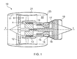
- a ducted fan gas turbine engine which incorporates many components which may be the subject of testing according to embodiments of the present invention is generally indicated at 10 and has a principal and rotational axis X-X.
- the engine comprises, in axial flow series, an air intake 11, a propulsive fan 12, an intermediate pressure compressor 13, a high-pressure compressor 14, combustion equipment 15, a high-pressure turbine 16, an intermediate pressure turbine 17, a low-pressure turbine 18 and a core engine exhaust nozzle 19.
- a nacelle 21 generally surrounds the engine 10 and defines the intake 11, a bypass duct 22 and a bypass exhaust nozzle 23.
- air entering the intake 11 is accelerated by the fan 12 to produce two air flows: a first air flow A into the intermediate pressure compressor 13 and a second air flow B which passes through the bypass duct 22 to provide propulsive thrust.
- the intermediate pressure compressor 13 compresses the air flow A directed into it before delivering that air to the high pressure compressor 14 where further compression takes place.
- the compressed air exhausted from the high-pressure compressor 14 is directed into the combustion equipment 15 where it is mixed with fuel and the mixture combusted.
- the resultant hot combustion products then expand through, and thereby drive the high, intermediate and low-pressure turbines 16, 17, 18 before being exhausted through the nozzle 19 to provide additional propulsive thrust.
- the high, intermediate and low-pressure turbines respectively drive the high and intermediate pressure compressors 14, 13 and the fan 12 by suitable interconnecting shafts.
- Components which may be tested using methods according to embodiments of the present invention include, but are not limited to, the fan blades and turbine blades of the compressor and well as components making up the nacelle 21.
- An embodiment of the present invention provides a testing process by which the mode shape and stress/strain distribution of the existing complete component, such as a fan blade or a turbine blade, is altered by attaching one or more masses to the component (for example by bonding, mechanical fastener or magnetic interaction).
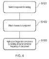
- Fig. 4 is a flowchart setting out the main steps in the method of this embodiment.
- Figs. 2a and 2b show the component 1 in the two configurations.
- the component 1 has no mass addition and deflects under vibration as shown by dotted line 1 a. This causes a position of highest stress 3a to be located near the base of the component.
- an additional mass 2 is added to the component 1 (step S102). This causes the component to deflect under vibration as shown by the dotted line 1 b, which is in a different manner to the unaltered component shown in Fig. 2a .
- the vibration of the component 1 with the additional mass 2 causes a position of highest stress 3b to be located at a position closer to the upper edge of the component where the mass is positioned.
- the new vibration characteristic can be calculated using a finite element model (including the additional masses) such as that set out below, and thus define the optimum positions to apply the masses in order to obtain the desired mode shapes.
- the FE model will predict modeshapes, frequencies and stresses for the original and modified component, allowing the effect of the additional masses, to be understood and the test to be defined using the modified component.
- the modified fundamental mode is much easier to excite than a complex mode, but will give a failure position at a point on the component which would fail in a more complex mode, or at other points in the blade (or other component) where there are known features such as defects or residual stresses.
- the component shown in Fig. 2b can thus be subject to high-cycle fatigue testing (step S103) by excitation at lower fundamental frequencies than would otherwise be required to create the appropriate stress distribution.
- the mass matrix [M] describes the mass distribution of the component
- the stiffness matrix [K] describes the stiffness distribution of the component
- N eigenvalues i.e. ⁇ 1 2 , ⁇ 2 2 , ... ⁇ N 2
- N corresponds to the number of degrees of freedom.
- the eigenvalues provide the natural frequencies of the system.
- the values of ⁇ X ⁇ that correspond to each eigenvalue are called the eigenvectors.
- These eigenvectors represent the mode shapes of the system.
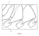
- Figure 3 shows a turbine aerofoil 1 where masses 2 have been added to induce a failure near the tip but in a fundamental (e.g. 1 F) mode.
- a fundamental e.g. 1 F
- the present invention is not limited to the testing of components of a gas turbine engine (or indeed an engine at all) but can be applied to a wide range of testing scenarios and components to be tested.
Landscapes
- Physics & Mathematics (AREA)
- General Physics & Mathematics (AREA)
- Engineering & Computer Science (AREA)
- Aviation & Aerospace Engineering (AREA)
- Chemical & Material Sciences (AREA)
- Combustion & Propulsion (AREA)
- Investigating Strength Of Materials By Application Of Mechanical Stress (AREA)
Abstract
Description
- The present invention relates to a method of component testing. The invention is particularly, but not exclusively, concerned with a method for failure-testing components in complex vibration modes.
- In complex products, such as gas turbine engines, it is common to test components extensively prior to manufacture.
- For many components a major form of testing is high cycle fatigue ("HCF") testing. This generally relates to situations where more than 104 cycles are required before failure, the stress is low and the deformation experienced is primarily elastic.
- Until now, HCF fatigue testing has typically been carried out either on a whole component, or a part of that component, the part being obtained by either extracting a sub-component or by machining away part of the original component. That component or sub-component would then be tested by exciting it at its resonant frequency or by forcing it into a 'flutter' type mode, until the component started to fail.
- However, components are difficult to excite in complex vibration mode shapes, which often occur at higher frequencies, because of the increased energy required to drive them to exhibit such vibration modes. In particular the drive system used in the testing, which may be a chopped air jet, a piezo-electric exciter, an electro-mechanical shaker, a constant air-jet which causes an aero-elastic instability such as flutter, typically is not able to supply the necessary energy to drive the component at high frequencies.
- At their broadest, aspects of the present invention provide processes by which fatigue testing can be carried out by altering the vibrational characteristics of a component, but without physically altering the component itself.
- A first aspect of the present invention provides a method of performing high-cycle fatigue testing on a component, the method including the steps of: attaching one or more masses to the component to alter the stress distribution of the component under vibration; and carrying out high-cycle fatigue testing by exciting the component at a low fundamental frequency of the component.
- The component can then be tested at a low frequency, which is easier to excite, but fail in a position of the component characteristic of a more complex modeshape.
- As the component is much easier to excite, this can mean a greatly reduced time on test therefore reducing cost, as there is less time taken to set up each test, and there is greater reliability in achieving a result. In some cases, such as if a defect in the material is identified, this is the only way to test for failure in the position of that defect. This could allow acceptance of such defects, and therefore potentially remove the need to scrap expensive components with such defects.
- Optional features of the invention will now be set out. These are applicable singly or in any combination with any aspect of the invention.
- In certain embodiments the low fundamental frequency is a frequency giving rise to the first flap or first torsion mode of vibration of the component.
- Preferably the method further includes the step of determining the vibration characteristic of the component with said masses attached using a finite element model.
- In one embodiment the finite element model includes determining the eigenvectors and eigenvalues of the equation

wherein [M] is the mass matrix which describes the mass distribution of the component, [K] is the stiffness matrix which describes the stiffness distribution of the component, and {x} is the displacement vector, and wherein the addition of the mass or masses changes the mass matrix [M] without changing the stiffness matrix [K] and is thus used to tune the system for specific eigenvectors. - Both the eigenvalues and eigenvectors will change after addition of the masses, and the system can therefore be tuned for specific eigenvectors by altering the position and magnitude of the masses, forcing the component to fail at the required position.
- The process can be used for vibration testing of any component, or system of components, where the vibrational characteristics of the component/system need to be changed, without changing the component itself.
- Embodiments of the invention will now be described by way of example with reference to the accompanying drawings in which:
-
Figure 1 shows a ducted fan gas turbine engine which incorporates components which may be the subject of testing according to embodiments of the present invention; -
Figure 2a shows the excitation of a component under HCF vibration testing in normal conditions; -
Figure 2b shows the excitation of the same component asFigure 2a under HCF vibration testing according to an embodiment of the present invention; -
Figure 3 shows a plurality of turbine blades with masses added for HCF vibration testing according to an embodiment of the present invention; and -
Figure 4 is a flow chart showing the main steps in a method of testing according to an embodiment of the present invention. - With reference to
Figure 1 , a ducted fan gas turbine engine which incorporates many components which may be the subject of testing according to embodiments of the present invention is generally indicated at 10 and has a principal and rotational axis X-X. The engine comprises, in axial flow series, anair intake 11, apropulsive fan 12, anintermediate pressure compressor 13, a high-pressure compressor 14,combustion equipment 15, a high-pressure turbine 16, anintermediate pressure turbine 17, a low-pressure turbine 18 and a coreengine exhaust nozzle 19. Anacelle 21 generally surrounds theengine 10 and defines theintake 11, abypass duct 22 and abypass exhaust nozzle 23. - During operation, air entering the
intake 11 is accelerated by thefan 12 to produce two air flows: a first air flow A into theintermediate pressure compressor 13 and a second air flow B which passes through thebypass duct 22 to provide propulsive thrust. Theintermediate pressure compressor 13 compresses the air flow A directed into it before delivering that air to thehigh pressure compressor 14 where further compression takes place. - The compressed air exhausted from the high-
pressure compressor 14 is directed into thecombustion equipment 15 where it is mixed with fuel and the mixture combusted. The resultant hot combustion products then expand through, and thereby drive the high, intermediate and low-pressure turbines nozzle 19 to provide additional propulsive thrust. The high, intermediate and low-pressure turbines respectively drive the high andintermediate pressure compressors fan 12 by suitable interconnecting shafts. - Components which may be tested using methods according to embodiments of the present invention include, but are not limited to, the fan blades and turbine blades of the compressor and well as components making up the
nacelle 21. - An embodiment of the present invention provides a testing process by which the mode shape and stress/strain distribution of the existing complete component, such as a fan blade or a turbine blade, is altered by attaching one or more masses to the component (for example by bonding, mechanical fastener or magnetic interaction).
Fig. 4 is a flowchart setting out the main steps in the method of this embodiment.Figs. 2a and 2b show thecomponent 1 in the two configurations. - In
Fig. 2a , thecomponent 1 has no mass addition and deflects under vibration as shown bydotted line 1 a. This causes a position ofhighest stress 3a to be located near the base of the component. - In
Fig. 2b , anadditional mass 2 is added to the component 1 (step S102). This causes the component to deflect under vibration as shown by thedotted line 1 b, which is in a different manner to the unaltered component shown inFig. 2a . The vibration of thecomponent 1 with theadditional mass 2 causes a position of highest stress 3b to be located at a position closer to the upper edge of the component where the mass is positioned. - The new vibration characteristic can be calculated using a finite element model (including the additional masses) such as that set out below, and thus define the optimum positions to apply the masses in order to obtain the desired mode shapes. The FE model will predict modeshapes, frequencies and stresses for the original and modified component, allowing the effect of the additional masses, to be understood and the test to be defined using the modified component.
- This allows the component to still be excited by traditional techniques, but at lower frequencies, e.g. that giving rise to the first flap or first torsion (1F or 1 T) mode, whilst creating the stress distribution characteristic of a more complex high frequency mode. Therefore the modified fundamental mode is much easier to excite than a complex mode, but will give a failure position at a point on the component which would fail in a more complex mode, or at other points in the blade (or other component) where there are known features such as defects or residual stresses.
- The component shown in
Fig. 2b can thus be subject to high-cycle fatigue testing (step S103) by excitation at lower fundamental frequencies than would otherwise be required to create the appropriate stress distribution. - For the general vibration case where there is no damping and no applied forces (i.e. free vibration), the mass matrix [M] describes the mass distribution of the component, and the stiffness matrix [K] describes the stiffness distribution of the component, then if the displacement vector is {x}:

- This differential equation can be solved by assuming the following type of solution:

- The equation then becomes:

- Since eiωt cannot equal zero the equation reduces to the following:

- This is referred to an eigenvalue problem in mathematics and can be put in the standard format by pre-multiplying the equation by [M]-1:

and if we let [M]1[K] = [A] and λ = ω 2 :
- The solution to the problem results in N eigenvalues (i.e.

- The eigenvalues and eigenvectors are often written in the following matrix format and describe the modal model of the system:

And
- With each eigenvector there is an associated modal strain and stress distribution, and the component will fail from fatigue in that mode at the point of maximum modal stress.
- The experimental method according to the embodiment of the invention described above alters the mass matrix in the equations above, but without altering the component itself and therefore the stiffness matrix. Both the eigenvalues and eigenvectors will change after addition of the masses, and the system can therefore be 'tuned' for specific eigenvectors by altering the position and magnitude of the masses, forcing the component to fail at the required position.
-
Figure 3 shows aturbine aerofoil 1 wheremasses 2 have been added to induce a failure near the tip but in a fundamental (e.g. 1 F) mode. - While the invention has been described in conjunction with the exemplary embodiments described above, many equivalent modifications and variations will be apparent to those skilled in the art when given this disclosure. Accordingly, the exemplary embodiments of the invention set forth above are considered to be illustrative and not limiting. Various changes to the described embodiments may be made without departing from the spirit and scope of the invention.
- In particular, the present invention is not limited to the testing of components of a gas turbine engine (or indeed an engine at all) but can be applied to a wide range of testing scenarios and components to be tested.
Claims (4)
- A method of performing high-cycle fatigue testing on a component (1), the method including the steps of:attaching one or more masses (2) to the component to alter the stress distribution of the component under vibration; andcarrying out high-cycle fatigue testing by exciting the component at a low fundamental frequency of the component.
- A method according to claim 1 wherein the low fundamental frequency is a frequency giving rise to the first flap or first torsion mode of vibration of the component.
- A method according to claim 1 or claim 2, further including the step of determining the vibration characteristic of the component with said masses attached using a finite element model.
- A method according to claim 3 wherein the finite element model includes determining the eigenvectors and eigenvalues of the equation

wherein [M] is the mass matrix which describes the mass distribution of the component, [K] is the stiffness matrix which describes the stiffness distribution of the component, and {x} is the displacement vector, and wherein the addition of the mass or masses changes the mass matrix [M] without changing the stiffness matrix [K] and is thus used to tune the system for specific eigenvectors.
Applications Claiming Priority (1)
| Application Number | Priority Date | Filing Date | Title |
|---|---|---|---|
| GBGB1414419.0A GB201414419D0 (en) | 2014-08-14 | 2014-08-14 | Method of testing |
Publications (2)
| Publication Number | Publication Date |
|---|---|
| EP2985584A1 true EP2985584A1 (en) | 2016-02-17 |
| EP2985584B1 EP2985584B1 (en) | 2018-01-10 |
Family
ID=51662409
Family Applications (1)
| Application Number | Title | Priority Date | Filing Date |
|---|---|---|---|
| EP15176739.9A Active EP2985584B1 (en) | 2014-08-14 | 2015-07-15 | Method of high-cycle testing of a gas turbine component |
Country Status (3)
| Country | Link |
|---|---|
| US (1) | US9880068B2 (en) |
| EP (1) | EP2985584B1 (en) |
| GB (1) | GB201414419D0 (en) |
Cited By (2)
| Publication number | Priority date | Publication date | Assignee | Title |
|---|---|---|---|---|
| EP3438634A1 (en) * | 2017-08-03 | 2019-02-06 | Siemens Aktiengesellschaft | Method of manufacturing and apparatus |
| CN118329354A (en) * | 2024-06-12 | 2024-07-12 | 西安航天动力研究所 | Test method for vibration fatigue test |
Families Citing this family (2)
| Publication number | Priority date | Publication date | Assignee | Title |
|---|---|---|---|---|
| FR3039676B1 (en) * | 2015-07-27 | 2017-08-25 | Snecma | METHOD FOR DETERMINING MAXIMUM ALTERNATIVE PERMISSIBLE STRESS FOR A PART SUBJECT TO CYCLIC SOLICITATION; UNIT FOR DETERMINING SUCH A CONSTRAINTS |
| CN113945388B (en) * | 2021-09-28 | 2024-04-19 | 太原理工大学 | Truncated test method for vibration fatigue test of aero-engine blade |
Citations (5)
| Publication number | Priority date | Publication date | Assignee | Title |
|---|---|---|---|---|
| DE1117913B (en) * | 1958-04-09 | 1961-11-23 | Elektropodnik Hl M Prahy | Resonance vibration device for carrying out fatigue tests on turbine blades and similar machine parts |
| US6601456B1 (en) * | 2001-06-06 | 2003-08-05 | Southwest Research Institute | Fretting fixture for high-cycle fatigue test machines |
| WO2004005879A1 (en) * | 2002-07-03 | 2004-01-15 | Midwest Research Institute | Resonance test system |
| US6813960B1 (en) * | 2002-08-19 | 2004-11-09 | Southwest Research Institute | Asymmetrical column assembly for high-cycle fatigue test machines |
| EP2423659A1 (en) * | 2010-08-27 | 2012-02-29 | General Electric Company | Methods and systems for assessing residual life of turbomachine airfoils |
Family Cites Families (8)
| Publication number | Priority date | Publication date | Assignee | Title |
|---|---|---|---|---|
| US3214969A (en) | 1963-06-24 | 1965-11-02 | Dehavilland Aircraft Canada | Apparatus for fatigue testing under random loads |
| US3911733A (en) * | 1974-04-01 | 1975-10-14 | Trw Inc | Optical signature method and apparatus for structural integrity verification |
| JPS58211627A (en) * | 1982-06-03 | 1983-12-09 | Mitsubishi Heavy Ind Ltd | Fatigue crack inserting method |
| US6330985B1 (en) | 2000-06-30 | 2001-12-18 | General Electric Company | Link component for aircraft engine mounting systems |
| US7016825B1 (en) * | 2000-10-26 | 2006-03-21 | Vextec Corporation | Method and apparatus for predicting the failure of a component |
| WO2009097049A2 (en) * | 2007-12-14 | 2009-08-06 | Alliance For Sustainable Energy, Llc | Dual-axis resonance testing of wind turbine blades |
| US8172511B2 (en) | 2009-05-04 | 2012-05-08 | Hamilton Sunstrand Corporation | Radial compressor with blades decoupled and tuned at anti-nodes |
| NL2010556C2 (en) | 2013-04-03 | 2014-10-06 | Onderzoekscentrum Voor Aanwending Van Staal N V | Fatigue testing of a test specimen. |
-
2014
- 2014-08-14 GB GBGB1414419.0A patent/GB201414419D0/en not_active Ceased
-
2015
- 2015-07-15 EP EP15176739.9A patent/EP2985584B1/en active Active
- 2015-07-15 US US14/800,153 patent/US9880068B2/en active Active
Patent Citations (5)
| Publication number | Priority date | Publication date | Assignee | Title |
|---|---|---|---|---|
| DE1117913B (en) * | 1958-04-09 | 1961-11-23 | Elektropodnik Hl M Prahy | Resonance vibration device for carrying out fatigue tests on turbine blades and similar machine parts |
| US6601456B1 (en) * | 2001-06-06 | 2003-08-05 | Southwest Research Institute | Fretting fixture for high-cycle fatigue test machines |
| WO2004005879A1 (en) * | 2002-07-03 | 2004-01-15 | Midwest Research Institute | Resonance test system |
| US6813960B1 (en) * | 2002-08-19 | 2004-11-09 | Southwest Research Institute | Asymmetrical column assembly for high-cycle fatigue test machines |
| EP2423659A1 (en) * | 2010-08-27 | 2012-02-29 | General Electric Company | Methods and systems for assessing residual life of turbomachine airfoils |
Cited By (3)
| Publication number | Priority date | Publication date | Assignee | Title |
|---|---|---|---|---|
| EP3438634A1 (en) * | 2017-08-03 | 2019-02-06 | Siemens Aktiengesellschaft | Method of manufacturing and apparatus |
| WO2019025194A1 (en) * | 2017-08-03 | 2019-02-07 | Siemens Aktiengesellschaft | Method of manufacturing and apparatus |
| CN118329354A (en) * | 2024-06-12 | 2024-07-12 | 西安航天动力研究所 | Test method for vibration fatigue test |
Also Published As
| Publication number | Publication date |
|---|---|
| US9880068B2 (en) | 2018-01-30 |
| EP2985584B1 (en) | 2018-01-10 |
| US20160047709A1 (en) | 2016-02-18 |
| GB201414419D0 (en) | 2014-10-01 |
Similar Documents
| Publication | Publication Date | Title |
|---|---|---|
| US6250166B1 (en) | Simulated dovetail testing | |
| EP2985584B1 (en) | Method of high-cycle testing of a gas turbine component | |
| US8024137B2 (en) | Method for determining blade mistuning on integrally manufactured rotor wheels | |
| CN105447272B (en) | A kind of turbine blade Reliability Design Method of Structural Vibration | |
| JP6622525B2 (en) | Random waveform load system and method, fatigue test program, and fatigue testing machine | |
| Schoenenborn et al. | Contribution to free and forced vibration analysis of an intentionally mistuned blisk | |
| CN108334716A (en) | Monocrystalline air film pole high-cycle fatigue life method | |
| CN113945388B (en) | Truncated test method for vibration fatigue test of aero-engine blade | |
| Lerche et al. | Dynamic stress prediction in centrifugal compressor blades using fluid structure interaction | |
| CN110849568B (en) | A test method for fatigue life of structures | |
| EP1217170A2 (en) | Method to tune the natural frequency of turbine blades by using the orientation of the secondary axes | |
| Manetti et al. | The dynamic influence of crystal orientation on a second generation single crystal material for turbine buckets | |
| Moradi et al. | Crack growth simulation in 13th row of compressor blades under foreign object damage and resonant vibration condition | |
| EP3741981A1 (en) | Mode-shaped components | |
| Weser et al. | Advanced experimental and analytical investigations on combined cycle fatigue (CCF) of conventional cast and single-crystal gas turbine blades | |
| Gao et al. | Engine vibration certification | |
| Busse et al. | A finite element study of the effect of crystal orientation and misalignment on the crack driving force in a single-crystal superalloy | |
| Ruffini et al. | The influence of mistuning and Coriolis effects on the modal parameters of bladed discs: An experimental study | |
| US11230926B2 (en) | High cycle fatigue design for gas turbine engines | |
| Lombard et al. | Mistuning phenomena on bladed disk: Industrial methods and applications | |
| Witek et al. | Crack propagation analysis of compressor blade subjected to resonant vibrations | |
| Herran et al. | Technological Choices for Vibratory Robustness of Turbine Bladed Disk | |
| Kotambkar et al. | Modeling and investigation of modal properties under crack induced mistuning in a turbine blade packet | |
| Muthu et al. | Life prediction of directionally solidified air cooled hpt gas turbine blade used in a supersonic aircraft using fem | |
| Sattar et al. | Design of jet engine rotors for long life |
Legal Events
| Date | Code | Title | Description |
|---|---|---|---|
| PUAI | Public reference made under article 153(3) epc to a published international application that has entered the european phase |
Free format text: ORIGINAL CODE: 0009012 |
|
| AK | Designated contracting states |
Kind code of ref document: A1 Designated state(s): AL AT BE BG CH CY CZ DE DK EE ES FI FR GB GR HR HU IE IS IT LI LT LU LV MC MK MT NL NO PL PT RO RS SE SI SK SM TR |
|
| AX | Request for extension of the european patent |
Extension state: BA ME |
|
| 17P | Request for examination filed |
Effective date: 20160816 |
|
| RBV | Designated contracting states (corrected) |
Designated state(s): AL AT BE BG CH CY CZ DE DK EE ES FI FR GB GR HR HU IE IS IT LI LT LU LV MC MK MT NL NO PL PT RO RS SE SI SK SM TR |
|
| STAA | Information on the status of an ep patent application or granted ep patent |
Free format text: STATUS: EXAMINATION IS IN PROGRESS |
|
| 17Q | First examination report despatched |
Effective date: 20161213 |
|
| REG | Reference to a national code |
Ref country code: DE Ref legal event code: R079 Ref document number: 602015007294 Country of ref document: DE Free format text: PREVIOUS MAIN CLASS: G01M0015140000 Ipc: G01M0007020000 |
|
| RIC1 | Information provided on ipc code assigned before grant |
Ipc: G01M 15/14 20060101ALI20170809BHEP Ipc: G01M 7/02 20060101AFI20170809BHEP Ipc: G01M 15/00 20060101ALI20170809BHEP Ipc: G01M 7/00 20060101ALI20170809BHEP Ipc: G01M 5/00 20060101ALI20170809BHEP |
|
| GRAP | Despatch of communication of intention to grant a patent |
Free format text: ORIGINAL CODE: EPIDOSNIGR1 |
|
| STAA | Information on the status of an ep patent application or granted ep patent |
Free format text: STATUS: GRANT OF PATENT IS INTENDED |
|
| GRAS | Grant fee paid |
Free format text: ORIGINAL CODE: EPIDOSNIGR3 |
|
| INTG | Intention to grant announced |
Effective date: 20171017 |
|
| GRAA | (expected) grant |
Free format text: ORIGINAL CODE: 0009210 |
|
| STAA | Information on the status of an ep patent application or granted ep patent |
Free format text: STATUS: THE PATENT HAS BEEN GRANTED |
|
| AK | Designated contracting states |
Kind code of ref document: B1 Designated state(s): AL AT BE BG CH CY CZ DE DK EE ES FI FR GB GR HR HU IE IS IT LI LT LU LV MC MK MT NL NO PL PT RO RS SE SI SK SM TR |
|
| REG | Reference to a national code |
Ref country code: CH Ref legal event code: EP Ref country code: AT Ref legal event code: REF Ref document number: 962935 Country of ref document: AT Kind code of ref document: T Effective date: 20180115 |
|
| REG | Reference to a national code |
Ref country code: IE Ref legal event code: FG4D |
|
| REG | Reference to a national code |
Ref country code: DE Ref legal event code: R096 Ref document number: 602015007294 Country of ref document: DE |
|
| REG | Reference to a national code |
Ref country code: NL Ref legal event code: MP Effective date: 20180110 |
|
| REG | Reference to a national code |
Ref country code: AT Ref legal event code: MK05 Ref document number: 962935 Country of ref document: AT Kind code of ref document: T Effective date: 20180110 |
|
| PG25 | Lapsed in a contracting state [announced via postgrant information from national office to epo] |
Ref country code: NL Free format text: LAPSE BECAUSE OF FAILURE TO SUBMIT A TRANSLATION OF THE DESCRIPTION OR TO PAY THE FEE WITHIN THE PRESCRIBED TIME-LIMIT Effective date: 20180110 |
|
| REG | Reference to a national code |
Ref country code: FR Ref legal event code: PLFP Year of fee payment: 4 |
|
| PG25 | Lapsed in a contracting state [announced via postgrant information from national office to epo] |
Ref country code: ES Free format text: LAPSE BECAUSE OF FAILURE TO SUBMIT A TRANSLATION OF THE DESCRIPTION OR TO PAY THE FEE WITHIN THE PRESCRIBED TIME-LIMIT Effective date: 20180110 Ref country code: HR Free format text: LAPSE BECAUSE OF FAILURE TO SUBMIT A TRANSLATION OF THE DESCRIPTION OR TO PAY THE FEE WITHIN THE PRESCRIBED TIME-LIMIT Effective date: 20180110 Ref country code: LT Free format text: LAPSE BECAUSE OF FAILURE TO SUBMIT A TRANSLATION OF THE DESCRIPTION OR TO PAY THE FEE WITHIN THE PRESCRIBED TIME-LIMIT Effective date: 20180110 Ref country code: NO Free format text: LAPSE BECAUSE OF FAILURE TO SUBMIT A TRANSLATION OF THE DESCRIPTION OR TO PAY THE FEE WITHIN THE PRESCRIBED TIME-LIMIT Effective date: 20180410 Ref country code: FI Free format text: LAPSE BECAUSE OF FAILURE TO SUBMIT A TRANSLATION OF THE DESCRIPTION OR TO PAY THE FEE WITHIN THE PRESCRIBED TIME-LIMIT Effective date: 20180110 Ref country code: CY Free format text: LAPSE BECAUSE OF FAILURE TO SUBMIT A TRANSLATION OF THE DESCRIPTION OR TO PAY THE FEE WITHIN THE PRESCRIBED TIME-LIMIT Effective date: 20180110 |
|
| PG25 | Lapsed in a contracting state [announced via postgrant information from national office to epo] |
Ref country code: LV Free format text: LAPSE BECAUSE OF FAILURE TO SUBMIT A TRANSLATION OF THE DESCRIPTION OR TO PAY THE FEE WITHIN THE PRESCRIBED TIME-LIMIT Effective date: 20180110 Ref country code: SE Free format text: LAPSE BECAUSE OF FAILURE TO SUBMIT A TRANSLATION OF THE DESCRIPTION OR TO PAY THE FEE WITHIN THE PRESCRIBED TIME-LIMIT Effective date: 20180110 Ref country code: IS Free format text: LAPSE BECAUSE OF FAILURE TO SUBMIT A TRANSLATION OF THE DESCRIPTION OR TO PAY THE FEE WITHIN THE PRESCRIBED TIME-LIMIT Effective date: 20180510 Ref country code: PL Free format text: LAPSE BECAUSE OF FAILURE TO SUBMIT A TRANSLATION OF THE DESCRIPTION OR TO PAY THE FEE WITHIN THE PRESCRIBED TIME-LIMIT Effective date: 20180110 Ref country code: GR Free format text: LAPSE BECAUSE OF FAILURE TO SUBMIT A TRANSLATION OF THE DESCRIPTION OR TO PAY THE FEE WITHIN THE PRESCRIBED TIME-LIMIT Effective date: 20180411 Ref country code: BG Free format text: LAPSE BECAUSE OF FAILURE TO SUBMIT A TRANSLATION OF THE DESCRIPTION OR TO PAY THE FEE WITHIN THE PRESCRIBED TIME-LIMIT Effective date: 20180410 Ref country code: RS Free format text: LAPSE BECAUSE OF FAILURE TO SUBMIT A TRANSLATION OF THE DESCRIPTION OR TO PAY THE FEE WITHIN THE PRESCRIBED TIME-LIMIT Effective date: 20180110 Ref country code: AT Free format text: LAPSE BECAUSE OF FAILURE TO SUBMIT A TRANSLATION OF THE DESCRIPTION OR TO PAY THE FEE WITHIN THE PRESCRIBED TIME-LIMIT Effective date: 20180110 |
|
| REG | Reference to a national code |
Ref country code: DE Ref legal event code: R097 Ref document number: 602015007294 Country of ref document: DE |
|
| PG25 | Lapsed in a contracting state [announced via postgrant information from national office to epo] |
Ref country code: RO Free format text: LAPSE BECAUSE OF FAILURE TO SUBMIT A TRANSLATION OF THE DESCRIPTION OR TO PAY THE FEE WITHIN THE PRESCRIBED TIME-LIMIT Effective date: 20180110 Ref country code: IT Free format text: LAPSE BECAUSE OF FAILURE TO SUBMIT A TRANSLATION OF THE DESCRIPTION OR TO PAY THE FEE WITHIN THE PRESCRIBED TIME-LIMIT Effective date: 20180110 Ref country code: AL Free format text: LAPSE BECAUSE OF FAILURE TO SUBMIT A TRANSLATION OF THE DESCRIPTION OR TO PAY THE FEE WITHIN THE PRESCRIBED TIME-LIMIT Effective date: 20180110 Ref country code: EE Free format text: LAPSE BECAUSE OF FAILURE TO SUBMIT A TRANSLATION OF THE DESCRIPTION OR TO PAY THE FEE WITHIN THE PRESCRIBED TIME-LIMIT Effective date: 20180110 |
|
| PLBE | No opposition filed within time limit |
Free format text: ORIGINAL CODE: 0009261 |
|
| STAA | Information on the status of an ep patent application or granted ep patent |
Free format text: STATUS: NO OPPOSITION FILED WITHIN TIME LIMIT |
|
| PG25 | Lapsed in a contracting state [announced via postgrant information from national office to epo] |
Ref country code: SM Free format text: LAPSE BECAUSE OF FAILURE TO SUBMIT A TRANSLATION OF THE DESCRIPTION OR TO PAY THE FEE WITHIN THE PRESCRIBED TIME-LIMIT Effective date: 20180110 Ref country code: CZ Free format text: LAPSE BECAUSE OF FAILURE TO SUBMIT A TRANSLATION OF THE DESCRIPTION OR TO PAY THE FEE WITHIN THE PRESCRIBED TIME-LIMIT Effective date: 20180110 Ref country code: SK Free format text: LAPSE BECAUSE OF FAILURE TO SUBMIT A TRANSLATION OF THE DESCRIPTION OR TO PAY THE FEE WITHIN THE PRESCRIBED TIME-LIMIT Effective date: 20180110 Ref country code: DK Free format text: LAPSE BECAUSE OF FAILURE TO SUBMIT A TRANSLATION OF THE DESCRIPTION OR TO PAY THE FEE WITHIN THE PRESCRIBED TIME-LIMIT Effective date: 20180110 |
|
| 26N | No opposition filed |
Effective date: 20181011 |
|
| PG25 | Lapsed in a contracting state [announced via postgrant information from national office to epo] |
Ref country code: SI Free format text: LAPSE BECAUSE OF FAILURE TO SUBMIT A TRANSLATION OF THE DESCRIPTION OR TO PAY THE FEE WITHIN THE PRESCRIBED TIME-LIMIT Effective date: 20180110 |
|
| REG | Reference to a national code |
Ref country code: CH Ref legal event code: PL |
|
| PG25 | Lapsed in a contracting state [announced via postgrant information from national office to epo] |
Ref country code: MC Free format text: LAPSE BECAUSE OF FAILURE TO SUBMIT A TRANSLATION OF THE DESCRIPTION OR TO PAY THE FEE WITHIN THE PRESCRIBED TIME-LIMIT Effective date: 20180110 Ref country code: LU Free format text: LAPSE BECAUSE OF NON-PAYMENT OF DUE FEES Effective date: 20180715 |
|
| REG | Reference to a national code |
Ref country code: BE Ref legal event code: MM Effective date: 20180731 |
|
| REG | Reference to a national code |
Ref country code: IE Ref legal event code: MM4A |
|
| PG25 | Lapsed in a contracting state [announced via postgrant information from national office to epo] |
Ref country code: IE Free format text: LAPSE BECAUSE OF NON-PAYMENT OF DUE FEES Effective date: 20180715 Ref country code: CH Free format text: LAPSE BECAUSE OF NON-PAYMENT OF DUE FEES Effective date: 20180731 Ref country code: LI Free format text: LAPSE BECAUSE OF NON-PAYMENT OF DUE FEES Effective date: 20180731 |
|
| PG25 | Lapsed in a contracting state [announced via postgrant information from national office to epo] |
Ref country code: BE Free format text: LAPSE BECAUSE OF NON-PAYMENT OF DUE FEES Effective date: 20180731 |
|
| PG25 | Lapsed in a contracting state [announced via postgrant information from national office to epo] |
Ref country code: MT Free format text: LAPSE BECAUSE OF NON-PAYMENT OF DUE FEES Effective date: 20180715 |
|
| PG25 | Lapsed in a contracting state [announced via postgrant information from national office to epo] |
Ref country code: TR Free format text: LAPSE BECAUSE OF FAILURE TO SUBMIT A TRANSLATION OF THE DESCRIPTION OR TO PAY THE FEE WITHIN THE PRESCRIBED TIME-LIMIT Effective date: 20180110 |
|
| PG25 | Lapsed in a contracting state [announced via postgrant information from national office to epo] |
Ref country code: PT Free format text: LAPSE BECAUSE OF FAILURE TO SUBMIT A TRANSLATION OF THE DESCRIPTION OR TO PAY THE FEE WITHIN THE PRESCRIBED TIME-LIMIT Effective date: 20180110 |
|
| PG25 | Lapsed in a contracting state [announced via postgrant information from national office to epo] |
Ref country code: HU Free format text: LAPSE BECAUSE OF FAILURE TO SUBMIT A TRANSLATION OF THE DESCRIPTION OR TO PAY THE FEE WITHIN THE PRESCRIBED TIME-LIMIT; INVALID AB INITIO Effective date: 20150715 Ref country code: MK Free format text: LAPSE BECAUSE OF NON-PAYMENT OF DUE FEES Effective date: 20180110 |
|
| P01 | Opt-out of the competence of the unified patent court (upc) registered |
Effective date: 20230528 |
|
| PGFP | Annual fee paid to national office [announced via postgrant information from national office to epo] |
Ref country code: DE Payment date: 20250728 Year of fee payment: 11 |
|
| PGFP | Annual fee paid to national office [announced via postgrant information from national office to epo] |
Ref country code: GB Payment date: 20250722 Year of fee payment: 11 |
|
| PGFP | Annual fee paid to national office [announced via postgrant information from national office to epo] |
Ref country code: FR Payment date: 20250725 Year of fee payment: 11 |