EP2985488A1 - One-way clutch device - Google Patents
One-way clutch device Download PDFInfo
- Publication number
- EP2985488A1 EP2985488A1 EP14774947.7A EP14774947A EP2985488A1 EP 2985488 A1 EP2985488 A1 EP 2985488A1 EP 14774947 A EP14774947 A EP 14774947A EP 2985488 A1 EP2985488 A1 EP 2985488A1
- Authority
- EP
- European Patent Office
- Prior art keywords
- sections
- axial direction
- engaging
- diameter
- concave
- Prior art date
- Legal status (The legal status is an assumption and is not a legal conclusion. Google has not performed a legal analysis and makes no representation as to the accuracy of the status listed.)
- Withdrawn
Links
- 238000006073 displacement reaction Methods 0.000 claims abstract description 29
- 239000002184 metal Substances 0.000 claims abstract description 11
- 229920003002 synthetic resin Polymers 0.000 claims description 7
- 239000000057 synthetic resin Substances 0.000 claims description 7
- 230000001419 dependent effect Effects 0.000 claims 1
- 238000010276 construction Methods 0.000 description 11
- 230000005540 biological transmission Effects 0.000 description 5
- 238000003825 pressing Methods 0.000 description 3
- 238000001746 injection moulding Methods 0.000 description 2
- 238000004519 manufacturing process Methods 0.000 description 2
- 239000007858 starting material Substances 0.000 description 2
- 238000005452 bending Methods 0.000 description 1
- 230000015572 biosynthetic process Effects 0.000 description 1
- 230000000694 effects Effects 0.000 description 1
- 238000003801 milling Methods 0.000 description 1
- 238000005096 rolling process Methods 0.000 description 1
Images





Classifications
-
- F—MECHANICAL ENGINEERING; LIGHTING; HEATING; WEAPONS; BLASTING
- F16—ENGINEERING ELEMENTS AND UNITS; GENERAL MEASURES FOR PRODUCING AND MAINTAINING EFFECTIVE FUNCTIONING OF MACHINES OR INSTALLATIONS; THERMAL INSULATION IN GENERAL
- F16D—COUPLINGS FOR TRANSMITTING ROTATION; CLUTCHES; BRAKES
- F16D41/00—Freewheels or freewheel clutches
- F16D41/06—Freewheels or freewheel clutches with intermediate wedging coupling members between an inner and an outer surface
- F16D41/064—Freewheels or freewheel clutches with intermediate wedging coupling members between an inner and an outer surface the intermediate members wedging by rolling and having a circular cross-section, e.g. balls
- F16D41/066—Freewheels or freewheel clutches with intermediate wedging coupling members between an inner and an outer surface the intermediate members wedging by rolling and having a circular cross-section, e.g. balls all members having the same size and only one of the two surfaces being cylindrical
- F16D41/067—Freewheels or freewheel clutches with intermediate wedging coupling members between an inner and an outer surface the intermediate members wedging by rolling and having a circular cross-section, e.g. balls all members having the same size and only one of the two surfaces being cylindrical and the members being distributed by a separate cage encircling the axis of rotation
-
- F—MECHANICAL ENGINEERING; LIGHTING; HEATING; WEAPONS; BLASTING
- F16—ENGINEERING ELEMENTS AND UNITS; GENERAL MEASURES FOR PRODUCING AND MAINTAINING EFFECTIVE FUNCTIONING OF MACHINES OR INSTALLATIONS; THERMAL INSULATION IN GENERAL
- F16D—COUPLINGS FOR TRANSMITTING ROTATION; CLUTCHES; BRAKES
- F16D41/00—Freewheels or freewheel clutches
- F16D41/06—Freewheels or freewheel clutches with intermediate wedging coupling members between an inner and an outer surface
- F16D41/064—Freewheels or freewheel clutches with intermediate wedging coupling members between an inner and an outer surface the intermediate members wedging by rolling and having a circular cross-section, e.g. balls
Definitions
- the present invention relates to a one-way clutch that makes it possible to transmit rotational force between two members that are combined so as to be concentric to each other only when the two members relatively rotate in a specified direction.
- One-way clutches that only transmit rotation motion in a specified direction are assembled in the rotation transmission portion of various kinds of mechanical devices such as a starter for an idling-stop vehicle, various kinds of auxiliary devices for an automobile such as an alternator and the like, an oil pump for a transmission, and the like.
- a one-way clutch and a rolling bearing may be made into a unit by using common parts. An example of such a one-way clutch device will be explained with reference to FIG. 8 and FIG. 9 .
- a one-way roller clutch 1 In this one-way clutch device, a one-way roller clutch 1, and a pair of cylindrical roller bearings 2a, 2b that are arranged so as to be adjacent to both sides in the axial direction of the roller clutch 1 are made into a unit by using a common inner ring 3.
- the inner ring 3 is made using metal plate, and comprises a cylindrical section 4, and a pair of outward-facing rim sections 5a, 5b that are formed by bending both end sections in the axial direction of the cylindrical section 4 outward in the radial direction.
- a cam surface 6 is provided in the middle section in the axial direction of the outer-circumferential surface of the cylindrical section 4 as an inner-diameter-side engaging surface of the roller clutch 1, and a pair of cylindrical inner raceways 7a, 7b of a pair of cylindrical roller bearings 2a, 2b are provided on both end sections in the axial direction of the cylindrical section 4.
- Plural concave cam sections 8 called ramp sections are formed on the cam surface 6 so as to be uniformly spaced in the circumferential direction.
- each of these concave cam sections 8 becomes larger going in a direction toward one side in the circumferential direction.
- the outer diameter of one of the inner raceways 7a located on one side in the axial direction is equal to or greater than the diameter of the circumscribed circle of the cam surface 6.
- the outer diameter of the other inner raceway 7b located on the other side in the axial direction is equal to or less than the diameter of the inscribed circle of the bottom of the groove of the concave cam sections 8.
- edges on both ends in the axial direction of these concave cam sections 8 are covered by stepped surfaces 9 and are not open in the axial direction.
- the edges of the other ends in the axial direction, which are the edges of the ends on the other side in the axial direction of the concave cam sections 8, are open in the axial direction.
- rollers 10 which are engaging elements of the roller clutch 1, a clutch retainer 11, and plural springs (not illustrated in the figures) are arranged on the outer-diameter side of the cam surface 6.
- the rollers 10 are made using a metal.
- the rollers 10 are held by the clutch retainer 11, and in a held state, are arranged so that there is one roller 10 on the outer-diameter side of each concave cam section 8.
- the clutch retainer 11 is made using a synthetic resin and formed into a cylindrical shape.
- the clutch retainer 11 has: a pair of ring-shaped rim sections 12a, 12b that are separated from each other in the axial direction and arranged so as to be concentric with each other; plural column sections 13 that span between the rim sections 12a, 12b and are arranged so as to be uniformly spaced in the circumferential direction; and protrusions 14a, 14b that are provided at plural locations in the circumferential direction of the inner-circumferential surfaces of the rim sections 12a, 12b.
- Pockets 15 for holding the rollers 10 so as to be able to roll freely and so as to be able to move a little in the circumferential direction are formed in portions that are surrounded on four sides by the pair of rim sections 12a, 12b and column sections 13 that are adjacent in the circumferential direction.
- the clutch retainer 11 is prevented from rotating with respect to the inner ring 3 by the protrusions 14a, 14b engaging with the concave cam sections 8.
- the springs are provided between the column sections 13 and the rollers 10, and elastically press the rollers 10 in a direction in which the depth of the concave cam sections 8 becomes smaller going in the circumferential direction.
- pluralitural cylindrical rollers 16a, 16b of the cylindrical roller bearings 2a, 2b, and cylindrical bearing retainers 17a, 17b that hold these rollers 16a, 16b so as to be able to roll freely are arranged on the outer-diameter side of the pair of inner raceways 7a, 7b.
- the cylindrical rollers 16a, 16b are made using a metal, and the bearing retainers 17a, 17b are made using a metal or a synthetic resin.
- the outward-facing flange section 5a that is located on one side in the axial direction is formed before the other components are arranged around the cylindrical section 4, so has a thickness dimension that is equal to the portion of the cylindrical section 4 where one adjacent inner raceway 7a is provided.
- the other outward-facing flange section 5b that is located on the other side in the axial direction is formed after the other components (at least the clutch retainer 1 and bearing retainers 17a, 17b) are arranged around the cylindrical section 4, so the thickness is thinner than the portion of the cylindrical section 4 where the other adjacent inner raceway 7a is provided.
- the inner ring 3 is fastened around the outside of an inner-diameter side member 18 such as a rotating shaft.
- an outer-diameter side member 19 such as a housing, pulley and the like is assembled on the outer-diameter side of the rollers 10 and cylindrical rollers 16a, 16b.
- a cylindrical surface 20, which is an outer-diameter side engaging surface, is provided on the portion of the inner-circumferential surface that faces the rollers 10, and a cylindrical outer raceway 21 is provided in the portion that faces the cylindrical rollers 16a, 16b.
- the cylindrical roller bearings 2a, 2b support radial loads that act between the inner-diameter side member 18 and the outer-diameter-side member 19, and relative rotation between the inner-diameter-side member 18 and outer-diameter-side member 19 is possible.
- the roller clutch 1 is able to transmit rotational force between the inner-diameter-side member and outer-diameter-side member 19 only when the inner-diameter-side member and the outer-diameter-side member 19 relatively rotate in a specified direction.
- step surfaces 9 the edges on one end in the axial direction of the concave cam sections 8 are covered by step surfaces 9. Therefore, the step surfaces 9 and the protrusions 14a that are provided on the inner-circumferential surface of one end in the axial direction of the clutch retainer 11 (left end section in FIG. 8 and FIG. 9 ) engage in the axial direction.
- the engagement between the step surfaces 9 and the protrusions 14a restricts displacement to one side in the axial direction of the clutch retainer 11 with respect to the inner ring 3.
- the clutch retainer 11 is prevented from displacing a large amount to one side in the axial direction during operation in the overrun state, and the retainer 17a of one roller bearing 2a is prevented from becoming strongly sandwiched between the clutch retainer 11 and one outward-facing flange section 5a.
- the clutch retainer 11 moves a large amount toward the other side in the axial direction, and there is a possibility that the bearing retainer 17b of the other roller bearing 2b will become strongly sandwiched between the clutch retainer 11 and the other outward-facing flange section 5b.
- the bearing retainer 17b becomes strongly sandwiched, the bearing retainer 17b is not able to rotate with respect to the inner ring 3, and there is a possibility that the overrun state will not be able to be maintained.
- Patent Literature 1 Japanese Patent No. 3,657,330
- the object of the present invention is to achieve construction of a one-way clutch device wherein the amount of additional processing to the inner ring is kept to a minimum, and that has means for restricting the displacement of a synthetic resin clutch retainer in the axial direction with respect to a metal inner ring.
- the one-way clutch of the present invention comprises:
- means are provided between the inner ring and the clutch retainer for restricting displacement in the axial direction of the clutch retainer with respect to the inner ring.
- the means for restricting the displacement in the axial direction of the clutch retainer comprises: concave engaging sections that are formed on the outer-circumferential surface of the inner ring, have a circular shape as seen in the radial direction, and have a concave inner surface; and convex engaging sections that are formed on the inner-circumferential surface of the clutch retainer, and have a shape engageable with the concave engaging sections; and by the concave engaging sections engaging with the convex engaging sections, the displacement in the axial direction of the clutch retainer is prevented.
- the concave engaging sections are semispherical concave sections.
- the means for restricting the displacement in the axial direction of the clutch retainer comprises a ring-shaped member that is fitted and fastened around the outside of the inner ring with an interference fit at a position that is adjacent to and faces at least one end surface of both end surfaces in the axial direction of the clutch retainer; and by at least one end surface of the clutch retainer engaging with the ring-shaped member, the displacement in the axial direction of the clutch retainer is prevented.
- the present invention is suitably applied to a one-way clutch device having construction as described below.
- the inner-diameter-side engaging surface comprises a cam surface on the outer-circumferential surface of the inner ring in which plural concave cam sections are formed so as to be uniformly spaced in the circumferential direction.
- the engaging elements comprise plural rollers that are arranged so that one roller is located on the outer-diameter side of each concave cam section.
- the clutch retainer comprises: a pair of ring-shaped rim sections that are separated in the axial direction and arranged so as to be concentric with each other; plural column sections that span between the pair of rim sections and are arranged so as to be spaced apart in the circumferential direction, and plural pockets that are formed in portions that are surrounded on four sides by the pair of rim sections and column sections of the plural column sections that are adjacent in the circumferential direction, and that hold the engaging elements.
- the concave engaging sections are formed in portions of the cam surface that are between concave cam sections of the plural concave cam section that are adjacent in the circumferential direction.
- the convex engaging sections are formed on the inner-circumferential surface of at least one rim section of the pair of rim sections.
- the inner ring comprises a cylindrical section that comprises the outer-circumferential surface, and an outward-facing flange section that is provided on at least one end section of both end sections in the axial direction of the cylindrical section; the inner-diameter-side engaging surface is provided in the middle section in the axial direction of the cylindrical section; a pair of inner raceways are provided on both end sections in the axial direction of the cylindrical section on both sides of the inner-diameter-side engaging surface of the outer-circumferential surface; and plural rollers and cylindrical bearing retainers that hold the rollers are arranged on the outer-diameter side of the pair of inner raceways.
- the one-way clutch of the present invention it is possible to restrict displacement in the axial direction of a clutch retainer with respect to an inner ring due to engagement between concave engaging sections that are formed on the outer-circumferential surface of a metal inner ring and convex engaging sections that are formed in the inner-circumferential surface of a synthetic resin clutch retainer, or due to engagement between a clutch retainer and a ring-shaped member. Therefore, the clutch retainer that is assembled on the outer-diameter side of the inner ring is prevented from accidentally coming out in the axial direction during assembly work.
- FIG. 1 to FIG. 5 illustrate a first example of an embodiment of the present invention.
- the one-way clutch device of this example as in the conventional example, has an inner ring 3, plural rollers 10 as plural engaging elements, and a clutch retainer 11a.
- the inner ring 3 has a cylindrical section 4, and a pair of outward-facing flange sections 7a, 7b that are provided on both end sections in the axial direction of the cylindrical section 4.
- Plural concave cam sections 8 are formed in the cam surface 6 so as to be uniformly spaced in the circumferential direction, and so that the depth of the concave cam sections 8 becomes greater going toward one side in the circumferential direction.
- a pair of cylindrical inner raceways 7a, 7b of a pair of cylindrical roller bearings 2a, 2b are provided on both sides of the cam surface 6 on both end sections in the axial direction of the outer-circumferential surface of the cylindrical section 4.
- the outer diameter of one of the inner raceways 7a that is located on one side in the axial direction left side in FIG. 1 and FIG.
- the plural rollers 10 of the roller clutch 1 are made of metal, and one roller 10 is arranged on the outer-diameter side (perimeter) of each concave cam section 8 of the cam surface 6, which is the inner-diameter-side engaging surface.
- the clutch retainer 11a is made of synthetic resin such that the entire body is formed into a cylindrical shape, and when holding the plural rollers 10, is arranged around the perimeter of the cam surface 6.
- the clutch retainer 11a has: a pair of ring shaped rim sections 12a, 12b that are separated in the axial direction and are arrange so as to be concentric with each other; plural column sections 13 that span between the pair of rim sections 12a, 12b, and arranged so as to be separated in the circumferential direction; and plural pockets 15 that are formed in portions that are surrounded on four sides by the pair of rim sections 12a, 12b and column sections 13 of the plural column sections 13 that are adjacent in the circumferential direction, with each pocket 15 holding one roller 10.
- Each of the rollers 10 is elastically pressed by a spring in the direction in the circumferential direction where the depth of the concave cam sections 8 becomes small.
- a feature of this example is that means for restricting displacement in the axial direction of the clutch retainer 11a with respect to the inner ring 3a is provided between the inner ring 3a and clutch retainer 11a.
- the construction and functions of the other parts are the same as those of the one-way clutch device having conventional construction, so duplicate explanations are omitted or simplified, and the following explanation will center on the feature of this example.
- a one-way clutch device that has a cam-type one-way clutch such as described above is used, however, the present invention can also be applied to a one-way clutch device that has a sprag one-way clutch in which sprags are used as the engaging elements.
- the inner-diameter-side engaging surface is a cylindrical surface.
- concave engaging sections 22 are formed at plural locations in the circumferential direction of the other end section in the axial direction of the cam surface 6 of the inner ring 3a (right end section in FIG. 1 and FIG. 2 ) in portions between every other adjacent concave cam section 8 in the circumferential direction.
- the number of locations of concave engaging sections 22 is arbitrary as long as the function of preventing displacement in the axial direction of the clutch retainer 11a is obtained, and these concave engaging sections 22 are preferably uniformly spaced in the circumferential direction.
- all of the concave engaging sections 22 have a semispherical shape.
- convex engaging sections 23 are formed at plural locations in the circumferential direction of the inner-circumferential surfaces of the rim section 12b on the other side in the axial direction of the clutch retainer 11a (right side in FIG. 1 and FIG. 2 ) that correspond to the concave engaging sections 22.
- the convex engaging sections 23 have a semispherical shape that matches the concave engaging sections 22.
- the concave engaging sections 22 are formed by pressing with the tip-end section of a punch after the concave cam sections are formed on the outer-circumferential surface of the inner ring 3a in a milling process or the like.
- the convex engaging sections 23 are formed at the same time as performing injection molding of the clutch retainer 11a.
- the shape of the concave engaging sections is preferably semispherical, however, alternatively, other arbitrary shapes such as an elliptical shape that is long in the circumferential direction can be used as the shape of the concave engaging sections as long as construction is such that displacement in the axial direction of the clutch retainer 11a can be prevented, and the width in the axial direction is not large.
- the displacement in the axial direction of the clutch retainer 11a with respect to the inner ring 3a is restricted due to the engagement between the concave engaging sections 22 and the convex engaging sections 23. Therefore, when assembling the one-way clutch device of this example, the clutch retainer 11a that is assembled on the outer-diameter side of the inner ring 3a is prevented from accidentally coming out on the other side in the axial direction from the outer-diameter side of the inner ring 3a in the stage before forming the other outward-facing flange section 5b (right outward-facing flange section in FIG. 1 and FIG. 2 ).
- the concave engaging sections 22 are formed as semispherical concave sections, so the tip-end surface of the punch that is used for forming the concave engaging sections 22 is a semispherical convex surface that corresponds to the inner surface of the concave engaging sections 22, and has excellent strength. Therefore, even when the diameter of the concave engaging sections 22 is small, it is possible to maintain the durability of the punch. In other words, it is possible to make the diameter of the concave engaging sections 22 small while maintaining the durability of the punch. Therefore, it is possible to keep the amount of processing of the inner ring 3a during formation of the concave engaging sections 22 to a minimum, and it is possible to keep the pressing force of the punch small. As a result, it is possible to uses a small device as the device for generating the pressing force of the punch, so it is possible to keep down manufacturing costs by that amount.
- the width in the circumferential direction on the cam surface 6 of the portions between concave cam sections 8 that are adjacent in the circumferential direction where the concave engaging sections 22 are formed must be kept a specified amount according to the diameter of the concave engaging sections 22.
- the diameter of the concave engaging sections 22 can be made sufficiently small, so it is not necessary to increase the width in the circumferential direction of the portions between concave cam sections 8 that are adjacent in the circumferential direction when forming the concave engaging sections 22, or even when the width is increased when forming the concave engaging sections 22, it is possible to sufficiently suppress that amount of increase.
- the convex engaging sections 23 can be formed at the same time as injection molding of the clutch retainer 11a.
- the work of assembling the clutch retainer 11a on the outer-diameter side of the cam surface 6 is performed by inserting the inner ring 3a into the inner-diameter side of the clutch retainer 11a from the opening on one end (left end in FIG. 1 and FIG. 2 ) in the axial direction of the clutch retainer 11a in the state before forming the other outward-facing flange section 5b on the other end section in the axial direction of the inner ring 3a.
- the convex engaging sections 23 elastically ride up onto the portions of the cam surface 6 between concave cam sections 8 that are adjacent in the circumferential direction from the edge on the other end (edge on the right end in FIG. 1 and FIG.
- the convex engaging sections 23 are only provided on the inner-circumferential surface of the other rim section 12b that is located on the other end section (right end section in FIG. 1 and FIG. 2 ) in the axial direction of the clutch retainer 11a, and the concave engaging sections 22 are provided on the other end section in the axial direction of the portions between concave cam sections 8 that are adjacent in the circumferential direction, so the sliding distance L (see FIG. 4 ) where the large sliding resistance force acts is very short. Therefore, it is possible to easily perform the work of inserting the inner ring 3a.
- a ring-shaped member 24 is fitted and fastened around the outside of the other end section (right end section in FIG. 6 and FIG. 7 ) in the axial direction of the cam surface 6 of the inner ring 3 with an interference fit at a location facing and adjacent to the surface on the other end in the axial direction (surface on the right end in FIG. 6 and FIG. 7 ) of the rim section 12b on the other side of the clutch retainer 11.
- displacement toward the other side in the axial direction (right side in FIG. 6 and FIG. 7 ) of the clutch retainer 11 with respect to the inner ring 3 is restricted based on the existence of the ring-shaped member 24.
- the ring-shaped member 24 and clutch retainer 11 are assembled around the outer-diameter side of the inner ring 3 in the stage before forming the other outward-facing flange section 5b (right outward-facing flange section in FIG. 6 and FIG. 7 ), and then after that, the clutch retainer 11 is prevented from accidentally coming out toward the other side in the axial direction from the outer-diameter side of the inner ring 3.
- the ring-shaped member 24 is simply fastened around the outside of the outer-circumferential surface of the inner ring 3 with an interference fit. Therefore, there is an advantage in that there is no need to perform additional processing of the inner ring 3 in order to add means for restricting displacement in the axial direction by using a ring-shaped member 24.
- the ring-shaped member 24 has a height in the radial direction that is the same as that of the rim section 12b on the other side of the clutch retainer 11, however, it is also possible to employ construction in which notches are provided in part in the axial direction on the inner-diameter side of the rim section on the other side of the clutch retainer so as to have a size and shape capable of housing the ring-shaped member, and the ring-shaped member is arranged so as to face and be adjacent to part of the surface on the other end in the axial direction of the clutch retainer.
- the construction and function of the other parts are the same as in the first example of an embodiment.
- construction was employed in which outward-facing flanges 5a, 5b are provided on both end sections in the axial direction of the inner ring 3a, however, when embodying the present invention, it is also possible to use construction in which one of the outward-facing flanges (for example, 5b) is eliminated.
- one of the outward-facing flanges for example, 5b
- the present invention can be widely applied to a one-way clutch that is assembled in the rotation transmission portion of various mechanical devices such as a starter for an idling-stop vehicle, various kinds of auxiliary devices for an automobile such as an alternator and the like, an oil pump for a transmission, and the like.
Landscapes
- Engineering & Computer Science (AREA)
- General Engineering & Computer Science (AREA)
- Mechanical Engineering (AREA)
- Rolling Contact Bearings (AREA)
- Mechanical Operated Clutches (AREA)
Abstract
Description
- The present invention relates to a one-way clutch that makes it possible to transmit rotational force between two members that are combined so as to be concentric to each other only when the two members relatively rotate in a specified direction.
- One-way clutches that only transmit rotation motion in a specified direction are assembled in the rotation transmission portion of various kinds of mechanical devices such as a starter for an idling-stop vehicle, various kinds of auxiliary devices for an automobile such as an alternator and the like, an oil pump for a transmission, and the like. Moreover, as disclosed in Japanese Patent No.
3,657,330 FIG. 8 andFIG. 9 . In this one-way clutch device, a one-way roller clutch 1, and a pair ofcylindrical roller bearings roller clutch 1 are made into a unit by using a commoninner ring 3. - The
inner ring 3 is made using metal plate, and comprises acylindrical section 4, and a pair of outward-facingrim sections cylindrical section 4 outward in the radial direction. Acam surface 6 is provided in the middle section in the axial direction of the outer-circumferential surface of thecylindrical section 4 as an inner-diameter-side engaging surface of theroller clutch 1, and a pair of cylindricalinner raceways cylindrical roller bearings cylindrical section 4. Pluralconcave cam sections 8 called ramp sections are formed on thecam surface 6 so as to be uniformly spaced in the circumferential direction. The depth of each of theseconcave cam sections 8 becomes larger going in a direction toward one side in the circumferential direction. Moreover, of the pair ofinner raceways inner raceways 7a located on one side in the axial direction (left side inFIG. 8 andFIG. 9 ) is equal to or greater than the diameter of the circumscribed circle of thecam surface 6. On the other hand, the outer diameter of the otherinner raceway 7b located on the other side in the axial direction (right side inFIG. 8 andFIG. 9 ) is equal to or less than the diameter of the inscribed circle of the bottom of the groove of theconcave cam sections 8. Therefore, of the edges on both ends in the axial direction of theseconcave cam sections 8, the edges on one end in the axial direction, which are the edges of the ends on one side in the axial direction of theconcave cam sections 8, are covered bystepped surfaces 9 and are not open in the axial direction. On the other hand, the edges of the other ends in the axial direction, which are the edges of the ends on the other side in the axial direction of theconcave cam sections 8, are open in the axial direction. -
Plural rollers 10, which are engaging elements of theroller clutch 1, aclutch retainer 11, and plural springs (not illustrated in the figures) are arranged on the outer-diameter side of thecam surface 6. Therollers 10 are made using a metal. Therollers 10 are held by theclutch retainer 11, and in a held state, are arranged so that there is oneroller 10 on the outer-diameter side of eachconcave cam section 8. On the other hand, theclutch retainer 11 is made using a synthetic resin and formed into a cylindrical shape. Theclutch retainer 11 has: a pair of ring-shaped rim sections plural column sections 13 that span between therim sections protrusions rim sections Pockets 15 for holding therollers 10 so as to be able to roll freely and so as to be able to move a little in the circumferential direction are formed in portions that are surrounded on four sides by the pair ofrim sections column sections 13 that are adjacent in the circumferential direction. Theclutch retainer 11 is prevented from rotating with respect to theinner ring 3 by theprotrusions concave cam sections 8. The springs are provided between thecolumn sections 13 and therollers 10, and elastically press therollers 10 in a direction in which the depth of theconcave cam sections 8 becomes smaller going in the circumferential direction. - Plural
cylindrical rollers cylindrical roller bearings cylindrical bearing retainers rollers inner raceways cylindrical rollers bearing retainers flange sections inner ring 3, the outward-facingflange section 5a that is located on one side in the axial direction is formed before the other components are arranged around thecylindrical section 4, so has a thickness dimension that is equal to the portion of thecylindrical section 4 where one adjacentinner raceway 7a is provided. On the other hand, the other outward-facingflange section 5b that is located on the other side in the axial direction is formed after the other components (at least theclutch retainer 1 and bearingretainers cylindrical section 4, so the thickness is thinner than the portion of thecylindrical section 4 where the other adjacentinner raceway 7a is provided. - When using this kind of one-way clutch device, the
inner ring 3 is fastened around the outside of an inner-diameter side member 18 such as a rotating shaft. Moreover, an outer-diameter side member 19 such as a housing, pulley and the like is assembled on the outer-diameter side of therollers 10 andcylindrical rollers side member 19 or another member such as an outer ring that is fitted and fastened on the inside of the outer-diameter-side member 19, acylindrical surface 20, which is an outer-diameter side engaging surface, is provided on the portion of the inner-circumferential surface that faces therollers 10, and a cylindricalouter raceway 21 is provided in the portion that faces thecylindrical rollers cylindrical roller bearings diameter side member 18 and the outer-diameter-side member 19, and relative rotation between the inner-diameter-side member 18 and outer-diameter-side member 19 is possible. On the other hand, theroller clutch 1 is able to transmit rotational force between the inner-diameter-side member and outer-diameter-side member 19 only when the inner-diameter-side member and the outer-diameter-side member 19 relatively rotate in a specified direction. - In other words, when the inner-diameter-
side member 18 and the outer-diameter-side member 19 relatively rotate in a specified direction, therollers 10 become wedged in the cylindrical space between thecam surface 6 andcylindrical surface 20 in the portions where the depth of theconcave cam sections 8 becomes small. As a result, a locked state occurs in which transmission of rotational force between the small-diameter-side member 18 and large-diameter-side member 19 is possible. On the other hand, when the inner-diameter-side member 18 and the outer-diameter-side member 19 relatively rotate in the opposite direction of the specified direction, the inner-diameter-side member 18 and the outer-diameter-side member 19 are set into an overrun state and rotational force cannot be transmitted between these members. - In the case of this kind of one-way clutch device, the edges on one end in the axial direction of the
concave cam sections 8 are covered bystep surfaces 9. Therefore, thestep surfaces 9 and theprotrusions 14a that are provided on the inner-circumferential surface of one end in the axial direction of the clutch retainer 11 (left end section inFIG. 8 andFIG. 9 ) engage in the axial direction. The engagement between thestep surfaces 9 and theprotrusions 14a restricts displacement to one side in the axial direction of theclutch retainer 11 with respect to theinner ring 3. Due to this restriction, theclutch retainer 11 is prevented from displacing a large amount to one side in the axial direction during operation in the overrun state, and theretainer 17a of one roller bearing 2a is prevented from becoming strongly sandwiched between theclutch retainer 11 and one outward-facingflange section 5a. - On the other hand, there are no step surfaces on the edges of the other end in the axial direction of the
concave cam sections 8 that theprotrusions 14b that are provided on the inner-circumferential surface of the other end section in the axial direction of the clutch retainer 11 (right end sections inFIG. 8 andFIG. 9 ) are able to engage with. Therefore, it is not possible to restrict displacement to the other side in the axial direction of theclutch retainer 11 with respect to theinner ring 3 by using theprotrusions 14b. Consequently, theclutch retainer 11 moves a large amount toward the other side in the axial direction, and there is a possibility that thebearing retainer 17b of the other roller bearing 2b will become strongly sandwiched between theclutch retainer 11 and the other outward-facingflange section 5b. When thebearing retainer 17b becomes strongly sandwiched, thebearing retainer 17b is not able to rotate with respect to theinner ring 3, and there is a possibility that the overrun state will not be able to be maintained. Furthermore, when assembling the one-way clutch device, there is a possibility that theclutch retainer 11 that is assembled on the outer-diameter side of theinner ring 3 in the stage before forming the other outward-facingflange section 5b will accidentally come out from the outer-diameter side of theinner ring 3 toward the other side in the axial direction. Therefore, the work of forming the other outward-facingflange section 5b must be performed while paying careful attention that theclutch retainer 11 does not come out, so this work becomes troublesome. - [Patent Literature 1] Japanese Patent No.
3,657,330 - In order to eliminate the problems described above, there is a need to provide means for restricting the displacement in the one-way clutch of the clutch retainer toward the other side in the axial direction with respect to the inner ring. However, because of the necessity of keeping down manufacturing costs, it is necessary to keep the amount of additional processing of the inner ring to a minimum.
- In consideration of the situation described above, the object of the present invention is to achieve construction of a one-way clutch device wherein the amount of additional processing to the inner ring is kept to a minimum, and that has means for restricting the displacement of a synthetic resin clutch retainer in the axial direction with respect to a metal inner ring.
- The one-way clutch of the present invention comprises:
- an inner ring that is made of metal and comprising an outer-circumferential surface, and an inner-diameter-side engaging surface that is formed on part in the axial direction of the outer-circumferential surface;
- plural engaging elements that are located around the perimeter of the inner-diameter-side engaging surface; and
- a clutch retainer that is made of synthetic resin and having an overall cylindrical shape, and that, when holding the plural engaging elements, is located around the perimeter of the inner-diameter-side engaging surface.
- Particularly, in the one-way clutch device of the present invention, means are provided between the inner ring and the clutch retainer for restricting displacement in the axial direction of the clutch retainer with respect to the inner ring.
- More specifically, the means for restricting the displacement in the axial direction of the clutch retainer comprises: concave engaging sections that are formed on the outer-circumferential surface of the inner ring, have a circular shape as seen in the radial direction, and have a concave inner surface; and convex engaging sections that are formed on the inner-circumferential surface of the clutch retainer, and have a shape engageable with the concave engaging sections; and by the concave engaging sections engaging with the convex engaging sections, the displacement in the axial direction of the clutch retainer is prevented. Preferably, the concave engaging sections are semispherical concave sections.
- Alternatively or additionally, the means for restricting the displacement in the axial direction of the clutch retainer comprises a ring-shaped member that is fitted and fastened around the outside of the inner ring with an interference fit at a position that is adjacent to and faces at least one end surface of both end surfaces in the axial direction of the clutch retainer; and by at least one end surface of the clutch retainer engaging with the ring-shaped member, the displacement in the axial direction of the clutch retainer is prevented.
- The present invention is suitably applied to a one-way clutch device having construction as described below. In other words, the inner-diameter-side engaging surface comprises a cam surface on the outer-circumferential surface of the inner ring in which plural concave cam sections are formed so as to be uniformly spaced in the circumferential direction. The engaging elements comprise plural rollers that are arranged so that one roller is located on the outer-diameter side of each concave cam section. The clutch retainer comprises: a pair of ring-shaped rim sections that are separated in the axial direction and arranged so as to be concentric with each other; plural column sections that span between the pair of rim sections and are arranged so as to be spaced apart in the circumferential direction, and plural pockets that are formed in portions that are surrounded on four sides by the pair of rim sections and column sections of the plural column sections that are adjacent in the circumferential direction, and that hold the engaging elements.
- When the means for restricting the displacement in the axial direction of the clutch retainer is constructed by the concave engaging sections and the convex engaging sections, preferably, the concave engaging sections are formed in portions of the cam surface that are between concave cam sections of the plural concave cam section that are adjacent in the circumferential direction. Moreover, preferably the convex engaging sections are formed on the inner-circumferential surface of at least one rim section of the pair of rim sections.
- Furthermore, in the one-way clutch device to which the present invention is applied, preferably the inner ring comprises a cylindrical section that comprises the outer-circumferential surface, and an outward-facing flange section that is provided on at least one end section of both end sections in the axial direction of the cylindrical section; the inner-diameter-side engaging surface is provided in the middle section in the axial direction of the cylindrical section; a pair of inner raceways are provided on both end sections in the axial direction of the cylindrical section on both sides of the inner-diameter-side engaging surface of the outer-circumferential surface; and plural rollers and cylindrical bearing retainers that hold the rollers are arranged on the outer-diameter side of the pair of inner raceways.
- With the one-way clutch of the present invention, it is possible to restrict displacement in the axial direction of a clutch retainer with respect to an inner ring due to engagement between concave engaging sections that are formed on the outer-circumferential surface of a metal inner ring and convex engaging sections that are formed in the inner-circumferential surface of a synthetic resin clutch retainer, or due to engagement between a clutch retainer and a ring-shaped member. Therefore, the clutch retainer that is assembled on the outer-diameter side of the inner ring is prevented from accidentally coming out in the axial direction during assembly work. Furthermore, during operating in the overrun state, the occurrence of a situation of not being able to suitably maintain the overrun state of the one-way clutch due to the clutch retainer coming in strong contact with bearing retainers that are arranged so as to be adjacent in the axial direction is prevented.
-
-
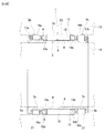
FIG. 1 is a cross-sectional view illustrating a one-way clutch device of a first example of an embodiment of the present invention. -
FIG. 2 is an exploded perspective view of an inner ring and clutch retainer of a one-way clutch device of the first example. -
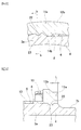
FIG. 3 is an enlarged cross-sectional view of section a-a inFIG. 1 . -
FIG. 4 is a cross-sectional view of section b-b inFIG. 3 . -
FIG. 5A is an enlarged view of area c inFIG. 2 , andFIG. 5B is an enlarged view of area d inFIG. 2 . -
FIG. 6 is a cross-sectional view illustrating a one-way clutch device of a second example of an embodiment of the present invention. -
FIG. 7 is an exploded perspective view of an inner ring, a clutch retainer and ring-shaped member of a one-way clutch of a second example. -
FIG. 8 is a cross-sectional view illustrating an example of a one-way clutch having conventional construction. -
FIG. 9 is an exploded perspective view of an inner ring and clutch retainer of the one-way clutch device inFIG. 8 . -
FIG. 1 to FIG. 5 illustrate a first example of an embodiment of the present invention. Basically, the one-way clutch device of this example, as in the conventional example, has aninner ring 3,plural rollers 10 as plural engaging elements, and aclutch retainer 11a. Theinner ring 3 has acylindrical section 4, and a pair of outward-facingflange sections cylindrical section 4. Acam surface 6, which is an inner-diameter-side engaging surface of aroller clutch 1, is provided in the middle section in the axial direction of the outer-circumferential surface of thecylindrical section 4. Pluralconcave cam sections 8 are formed in thecam surface 6 so as to be uniformly spaced in the circumferential direction, and so that the depth of theconcave cam sections 8 becomes greater going toward one side in the circumferential direction. Moreover, a pair of cylindricalinner raceways cylindrical roller bearings cam surface 6 on both end sections in the axial direction of the outer-circumferential surface of thecylindrical section 4. The outer diameter of one of theinner raceways 7a that is located on one side in the axial direction (left side inFIG. 1 andFIG. 2 ) is equal to or greater than the diameter of the circumscribed circle of thecam surface 6, and the outer diameter of the otherinner raceway 7b that is located on the other side in the axial direction (right side inFIG. 1 andFIG. 2 ) is equal to or less than the diameter of the inscribed circle of the groove bottom of theconcave cam sections 8. Pluralcylindrical rollers cylindrical bearing retainers cylindrical rollers inner raceways - The
plural rollers 10 of theroller clutch 1 are made of metal, and oneroller 10 is arranged on the outer-diameter side (perimeter) of eachconcave cam section 8 of thecam surface 6, which is the inner-diameter-side engaging surface. Theclutch retainer 11a is made of synthetic resin such that the entire body is formed into a cylindrical shape, and when holding theplural rollers 10, is arranged around the perimeter of thecam surface 6. Theclutch retainer 11a has: a pair of ring shapedrim sections plural column sections 13 that span between the pair ofrim sections plural pockets 15 that are formed in portions that are surrounded on four sides by the pair ofrim sections column sections 13 of theplural column sections 13 that are adjacent in the circumferential direction, with eachpocket 15 holding oneroller 10. Each of therollers 10 is elastically pressed by a spring in the direction in the circumferential direction where the depth of theconcave cam sections 8 becomes small. - A feature of this example is that means for restricting displacement in the axial direction of the
clutch retainer 11a with respect to theinner ring 3a is provided between theinner ring 3a andclutch retainer 11a. The construction and functions of the other parts are the same as those of the one-way clutch device having conventional construction, so duplicate explanations are omitted or simplified, and the following explanation will center on the feature of this example. In the example described below, a one-way clutch device that has a cam-type one-way clutch such as described above is used, however, the present invention can also be applied to a one-way clutch device that has a sprag one-way clutch in which sprags are used as the engaging elements. In that case, the inner-diameter-side engaging surface is a cylindrical surface. - In this example, concave engaging
sections 22 are formed at plural locations in the circumferential direction of the other end section in the axial direction of thecam surface 6 of theinner ring 3a (right end section inFIG. 1 andFIG. 2 ) in portions between every other adjacentconcave cam section 8 in the circumferential direction. However, the number of locations of concaveengaging sections 22 is arbitrary as long as the function of preventing displacement in the axial direction of theclutch retainer 11a is obtained, and these concaveengaging sections 22 are preferably uniformly spaced in the circumferential direction. In this example, all of the concaveengaging sections 22 have a semispherical shape. On the other hand, convex engagingsections 23 are formed at plural locations in the circumferential direction of the inner-circumferential surfaces of therim section 12b on the other side in the axial direction of theclutch retainer 11a (right side inFIG. 1 andFIG. 2 ) that correspond to the concaveengaging sections 22. In this example, the convexengaging sections 23 have a semispherical shape that matches the concaveengaging sections 22. When theclutch retainer 11a is assembled on the outer-diameter side of thecam surface 6, the convexengaging sections 23 firmly fit with the concaveengaging sections 22. As a result, displacement in the axial direction of theclutch retainer 11a with respect to theinner ring 3a is restricted. In this example, the concaveengaging sections 22 are formed by pressing with the tip-end section of a punch after the concave cam sections are formed on the outer-circumferential surface of theinner ring 3a in a milling process or the like. On the other hand, the convexengaging sections 23 are formed at the same time as performing injection molding of theclutch retainer 11a. From the aspect of keeping the amount of additional processing of theinner ring 3a to a minimum, the shape of the concave engaging sections is preferably semispherical, however, alternatively, other arbitrary shapes such as an elliptical shape that is long in the circumferential direction can be used as the shape of the concave engaging sections as long as construction is such that displacement in the axial direction of theclutch retainer 11a can be prevented, and the width in the axial direction is not large. - In the case of the one-way clutch device of this example, the displacement in the axial direction of the
clutch retainer 11a with respect to theinner ring 3a is restricted due to the engagement between the concaveengaging sections 22 and the convexengaging sections 23. Therefore, when assembling the one-way clutch device of this example, theclutch retainer 11a that is assembled on the outer-diameter side of theinner ring 3a is prevented from accidentally coming out on the other side in the axial direction from the outer-diameter side of theinner ring 3a in the stage before forming the other outward-facingflange section 5b (right outward-facing flange section inFIG. 1 andFIG. 2 ). Furthermore, failure to suitably maintain the overrun state of the one-way clutch device due to the bearingretainer 17b of the othercylindrical roller bearing 2b being strongly sandwiched between theclutch retainer 11a and the other outward-facingflange section 5b during operation in the overrun state is prevented. - Moreover, the concave
engaging sections 22 are formed as semispherical concave sections, so the tip-end surface of the punch that is used for forming the concaveengaging sections 22 is a semispherical convex surface that corresponds to the inner surface of the concaveengaging sections 22, and has excellent strength. Therefore, even when the diameter of the concaveengaging sections 22 is small, it is possible to maintain the durability of the punch. In other words, it is possible to make the diameter of the concaveengaging sections 22 small while maintaining the durability of the punch. Therefore, it is possible to keep the amount of processing of theinner ring 3a during formation of the concaveengaging sections 22 to a minimum, and it is possible to keep the pressing force of the punch small. As a result, it is possible to uses a small device as the device for generating the pressing force of the punch, so it is possible to keep down manufacturing costs by that amount. - Moreover, the width in the circumferential direction on the
cam surface 6 of the portions betweenconcave cam sections 8 that are adjacent in the circumferential direction where the concaveengaging sections 22 are formed must be kept a specified amount according to the diameter of the concaveengaging sections 22. In this regard, in this example, the diameter of the concaveengaging sections 22 can be made sufficiently small, so it is not necessary to increase the width in the circumferential direction of the portions betweenconcave cam sections 8 that are adjacent in the circumferential direction when forming the concaveengaging sections 22, or even when the width is increased when forming the concaveengaging sections 22, it is possible to sufficiently suppress that amount of increase. Moreover, in regard to the diameter of thecam surface 6 as well, it is not necessary to increase the diameter when forming the concaveengaging sections 22, or even when the width is increased when forming the concaveengaging sections 22, it is possible to sufficiently suppress the amount of increase. On the other hand, the convexengaging sections 23 can be formed at the same time as injection molding of theclutch retainer 11a. - The work of assembling the
clutch retainer 11a on the outer-diameter side of thecam surface 6 is performed by inserting theinner ring 3a into the inner-diameter side of theclutch retainer 11a from the opening on one end (left end inFIG. 1 andFIG. 2 ) in the axial direction of theclutch retainer 11a in the state before forming the other outward-facingflange section 5b on the other end section in the axial direction of theinner ring 3a. When doing this, the convexengaging sections 23 elastically ride up onto the portions of thecam surface 6 betweenconcave cam sections 8 that are adjacent in the circumferential direction from the edge on the other end (edge on the right end inFIG. 1 andFIG. 2 ) in the axial direction of these portions betweenconcave cam sections 8 that are adjacent in the circumferential direction. Then, after sliding and moving in the axial direction over these portions betweenconcave cam sections 8 that are adjacent in the circumferential direction, the convexengaging sections 23 are elastically restored when aligned with the concaveengaging sections 22, and fit with the concaveengaging sections 22. When the convexengaging sections 23 slide and move in the axial direction over the portions betweenconcave cam sections 8 that are adjacent in the circumferential direction in this way, a large sliding resistance force acts between the convexengaging sections 23 and the portions betweenconcave cam sections 8 that are adjacent in the circumferential direction. However, in this example, the convexengaging sections 23 are only provided on the inner-circumferential surface of theother rim section 12b that is located on the other end section (right end section inFIG. 1 andFIG. 2 ) in the axial direction of theclutch retainer 11a, and the concaveengaging sections 22 are provided on the other end section in the axial direction of the portions betweenconcave cam sections 8 that are adjacent in the circumferential direction, so the sliding distance L (seeFIG. 4 ) where the large sliding resistance force acts is very short. Therefore, it is possible to easily perform the work of inserting theinner ring 3a. - In this example, it is also possible to restrict the displacement in the circumferential direction of the
clutch retainer 11a with respect to theinner ring 3a based on the engagement between the concaveengaging sections 22 and the convexengaging sections 23. Therefore, it is also possible to eliminate theprotrusions clutch retainer 11a that are separately provided in order to restrict the displacement in the circumferential direction. However, in order to surely restrict the displacement in the circumferential direction of theclutch retainer 11a and to maintain reliability of the one-way clutch, it is preferred that theprotrusions - In this example, a ring-shaped
member 24 is fitted and fastened around the outside of the other end section (right end section inFIG. 6 andFIG. 7 ) in the axial direction of thecam surface 6 of theinner ring 3 with an interference fit at a location facing and adjacent to the surface on the other end in the axial direction (surface on the right end inFIG. 6 andFIG. 7 ) of therim section 12b on the other side of theclutch retainer 11. In this example, displacement toward the other side in the axial direction (right side inFIG. 6 andFIG. 7 ) of theclutch retainer 11 with respect to theinner ring 3 is restricted based on the existence of the ring-shapedmember 24. - Therefore, when assembling the one-way clutch device of this example, the ring-shaped
member 24 andclutch retainer 11 are assembled around the outer-diameter side of theinner ring 3 in the stage before forming the other outward-facingflange section 5b (right outward-facing flange section inFIG. 6 andFIG. 7 ), and then after that, theclutch retainer 11 is prevented from accidentally coming out toward the other side in the axial direction from the outer-diameter side of theinner ring 3. Furthermore, during operation in the overrun state, problems such as failure to suitably maintain the overrun state of the one-way clutch device due to the bearingretainer 17b of the othercylindrical roller bearing 2b being strongly sandwiched between theclutch retainer 11 and other outward-facingflange section 5b are prevented. Moreover, in this example, the ring-shapedmember 24 is simply fastened around the outside of the outer-circumferential surface of theinner ring 3 with an interference fit. Therefore, there is an advantage in that there is no need to perform additional processing of theinner ring 3 in order to add means for restricting displacement in the axial direction by using a ring-shapedmember 24. - In this example, the ring-shaped
member 24 has a height in the radial direction that is the same as that of therim section 12b on the other side of theclutch retainer 11, however, it is also possible to employ construction in which notches are provided in part in the axial direction on the inner-diameter side of the rim section on the other side of the clutch retainer so as to have a size and shape capable of housing the ring-shaped member, and the ring-shaped member is arranged so as to face and be adjacent to part of the surface on the other end in the axial direction of the clutch retainer. The construction and function of the other parts are the same as in the first example of an embodiment. - In the embodiments described above, construction was employed in which outward-facing
flanges inner ring 3a, however, when embodying the present invention, it is also possible to use construction in which one of the outward-facing flanges (for example, 5b) is eliminated. When using such construction, it is possible to restrict the displacement in the axial direction of the bearing retainer on the side of the eliminated outward-facing flange section (for example, bearingretainer 17b) by arranging part of the other member located around the perimeter at a position that faces the surface on the outer end in the axial direction of that bearing retainer during use. - The present invention can be widely applied to a one-way clutch that is assembled in the rotation transmission portion of various mechanical devices such as a starter for an idling-stop vehicle, various kinds of auxiliary devices for an automobile such as an alternator and the like, an oil pump for a transmission, and the like.
-
- 1 Roller clutch
- 2a, 2b Cylindrical roller bearing
- 3, 3a Inner ring
- 4 Cylindrical section
- 5a, 5b Outward-facing flange section
- 6 Cam surface
- 7a, 7b Inner raceway
- 8 Concave cam section
- 9 Step section
- 10 Roller
- 11, 11a Clutch retainer
- 12a, 12b Rim section
- 13 Column section
- 14a, 14b Protrusion
- 15 Pocket
- 16a, 16b Cylindrical roller
- 17a, 17b Bearing retainer
- 18 Inner-diameter-side member
- 19 Outer-diameter-side member
- 20 Cylindrical surface
- 21 Outer raceway
- 22 Concave engaging section
- 23 Convex engaging section
- 24 Ring-shaped member
Claims (6)
- A one-way clutch device, comprising:an inner ring made of metal and comprising an outer-circumferential surface, and an inner-diameter-side engaging surface that is formed on part in an axial direction of the outer-circumferential surface;plural engaging elements located around a perimeter of the inner-diameter-side engaging surface;a clutch retainer made of synthetic resin and having an overall cylindrical shape, and, with holding the plural engaging elements, being located around the perimeter of the inner-diameter-side engaging surface; anda means provided between the inner ring and the clutch retainer for restricting displacement in the axial direction of the clutch retainer with respect to the inner ring.
- The one-way clutch device according to Claim 1, wherein
the means for restricting the displacement in the axial direction of the clutch retainer comprises: concave engaging sections that are formed on the outer-circumferential surface of the inner ring, have a circular shape as seen in a radial direction, and have a concave inner surface; and convex engaging sections that are formed on an inner-circumferential surface of the clutch retainer, and have a shape engageable with the concave engaging sections; and by the concave engaging sections engaging with the convex engaging sections, the displacement in the axial direction of the clutch retainer is prevented. - The one-way clutch device according to Claim 1, wherein
the means for restricting the displacement in the axial direction of the clutch retainer comprises a ring-shaped member that is fitted and fastened around an outside of the inner ring with an interference fit at a position that is adjacent to and faces at least one end surface of both end surfaces in the axial direction of the clutch retainer; and by the at least one end surface of the clutch retainer engaging with the ring-shaped member, the displacement in the axial direction of the clutch retainer is prevented. - The one-way clutch device according to Claim 1, wherein
the inner-diameter-side engaging surface comprises a cam surface on the outer-circumferential surface of the inner ring in which plural concave cam sections are formed so as to be uniformly spaced in a circumferential direction;
the engaging elements comprise plural rollers that are arranged so that one roller is located on an outer-diameter side of each concave cam section; and
the clutch retainer comprises: a pair of ring-shaped rim sections that are separated in the axial direction and arranged so as to be concentric with each other; plural column sections that span between the pair of rim sections and are arranged so as to be spaced apart in the circumferential direction; and plural pockets that are formed in portions that are surrounded on four sides by the pair of rim sections and column sections of the plural column sections that are adjacent in the circumferential direction and that hold the engaging elements. - The one-way clutch device according to Claim 4 that is dependent on Claim 2, wherein
the concave engaging sections are formed in portions of the cam surface that are between concave cam sections of the plural concave cam sections that are adjacent in the circumferential direction; and the convex engaging sections are formed on the inner-circumferential surface of at least one rim section of the pair of rim sections. - The one-way clutch device according to Claim 4, wherein
the inner ring comprises a cylindrical section that comprises the outer-circumferential surface, and an outward-facing flange section that is provided on at least one end section of both end sections in the axial direction of the cylindrical section; the inner-diameter-side engaging surface is provided in the middle section in the axial direction of the cylindrical section; a pair of inner raceways are provided on both end sections in the axial direction of the cylindrical section on both sides of the inner-diameter-side engaging surface of the outer-circumferential surface; and plural rollers and cylindrical bearing retainers that hold the rollers are arranged on an outer-diameter side of the pair of inner raceways.
Applications Claiming Priority (3)
| Application Number | Priority Date | Filing Date | Title |
|---|---|---|---|
| JP2013063156 | 2013-03-26 | ||
| JP2013063265 | 2013-03-26 | ||
| PCT/JP2014/058338 WO2014157236A1 (en) | 2013-03-26 | 2014-03-25 | One-way clutch device |
Publications (2)
| Publication Number | Publication Date |
|---|---|
| EP2985488A1 true EP2985488A1 (en) | 2016-02-17 |
| EP2985488A4 EP2985488A4 (en) | 2017-01-11 |
Family
ID=51624205
Family Applications (1)
| Application Number | Title | Priority Date | Filing Date |
|---|---|---|---|
| EP14774947.7A Withdrawn EP2985488A4 (en) | 2013-03-26 | 2014-03-25 | One-way clutch device |
Country Status (5)
| Country | Link |
|---|---|
| US (1) | US9982726B2 (en) |
| EP (1) | EP2985488A4 (en) |
| JP (1) | JP6128207B2 (en) |
| CN (1) | CN105026783B (en) |
| WO (1) | WO2014157236A1 (en) |
Families Citing this family (4)
| Publication number | Priority date | Publication date | Assignee | Title |
|---|---|---|---|---|
| JP2017110729A (en) * | 2015-12-16 | 2017-06-22 | 株式会社ジェイテクト | One-way clutch |
| JP2017110723A (en) * | 2015-12-16 | 2017-06-22 | 株式会社ジェイテクト | One-way clutch |
| DE102019133200B3 (en) | 2019-12-05 | 2021-03-11 | Schaeffler Technologies AG & Co. KG | Roller freewheel unit for a vehicle, vehicle with a roller freewheel unit and use and method for assembling the roller freewheel unit |
| DE102021120521B3 (en) * | 2021-08-06 | 2022-07-28 | Schaeffler Technologies AG & Co. KG | Freewheel with form-fitting connection between sheet metal cage and freewheel body with coupling disc |
Family Cites Families (18)
| Publication number | Priority date | Publication date | Assignee | Title |
|---|---|---|---|---|
| US3548982A (en) * | 1968-09-26 | 1970-12-22 | Pavel Alexandrovich Soloviev | Free-wheeling clutch |
| JPH074341Y2 (en) * | 1988-09-19 | 1995-02-01 | 光洋精工株式会社 | Hand clutch |
| JP2529873Y2 (en) * | 1991-02-15 | 1997-03-19 | ダイワ精工株式会社 | Fishing reel |
| DE4442404C2 (en) * | 1994-11-30 | 1999-07-01 | Schaeffler Waelzlager Ohg | Anti-rotation device for a plastic cage of a freewheel |
| JP2942488B2 (en) * | 1995-11-30 | 1999-08-30 | 株式会社椿本エマソン | Lift-off type motor with one-way clutch mechanism |
| CN1069122C (en) * | 1996-12-20 | 2001-08-01 | Nsk沃纳株式会社 | Sprag type one-way clutch |
| JP3730736B2 (en) * | 1996-12-25 | 2006-01-05 | Nskワーナー株式会社 | One-way clutch having a cage with a bearing function |
| JPH1163028A (en) * | 1997-08-26 | 1999-03-05 | Nsk Warner Kk | Sprag one-way clutch |
| JP3731703B2 (en) * | 1998-02-16 | 2006-01-05 | 光洋精工株式会社 | Pulley unit |
| JP2000104758A (en) * | 1998-09-30 | 2000-04-11 | Nsk Ltd | Roller clutch |
| JP4318335B2 (en) * | 1999-01-27 | 2009-08-19 | Ntn株式会社 | One-way clutch |
| JP2000240461A (en) * | 1999-02-23 | 2000-09-05 | Nsk Ltd | Pulley device with built-in one-way clutch for alternator and method of preventing squeal of endless belt for driving alternator |
| JP2001165201A (en) * | 1999-12-14 | 2001-06-19 | Nsk Ltd | Rotary transmission with built-in one-way clutch |
| KR100799792B1 (en) * | 2000-03-28 | 2008-01-31 | 닛뽄 세이꼬 가부시기가이샤 | Rotational transmission with built-in one-way clutch |
| JP3652207B2 (en) * | 2000-03-28 | 2005-05-25 | 日本精工株式会社 | One-way clutch built-in type rotation transmission device |
| JP3681954B2 (en) * | 2000-05-09 | 2005-08-10 | 三菱電機株式会社 | One-way clutch built-in type rotation transmission device |
| JP2007064348A (en) * | 2005-08-31 | 2007-03-15 | Ntn Corp | One-way clutch and clutch-incorporated pulley |
| JP2008008349A (en) * | 2006-06-28 | 2008-01-17 | Jtekt Corp | One-way clutch |
-
2014
- 2014-03-25 US US14/771,950 patent/US9982726B2/en not_active Expired - Fee Related
- 2014-03-25 CN CN201480010263.9A patent/CN105026783B/en not_active Expired - Fee Related
- 2014-03-25 WO PCT/JP2014/058338 patent/WO2014157236A1/en not_active Ceased
- 2014-03-25 EP EP14774947.7A patent/EP2985488A4/en not_active Withdrawn
- 2014-03-25 JP JP2015508558A patent/JP6128207B2/en active Active
Also Published As
| Publication number | Publication date |
|---|---|
| WO2014157236A1 (en) | 2014-10-02 |
| CN105026783B (en) | 2018-03-02 |
| CN105026783A (en) | 2015-11-04 |
| JPWO2014157236A1 (en) | 2017-02-16 |
| US20160010705A1 (en) | 2016-01-14 |
| US9982726B2 (en) | 2018-05-29 |
| JP6128207B2 (en) | 2017-05-17 |
| EP2985488A4 (en) | 2017-01-11 |
Similar Documents
| Publication | Publication Date | Title |
|---|---|---|
| EP2423524B1 (en) | Thrust roller bearing and method of manufacturing thrust race thereof | |
| EP2886900A1 (en) | Roller clutch equipped with support bearing | |
| US8393452B2 (en) | One way clutch | |
| JPWO2003067128A1 (en) | Rotation transmission device with built-in roller clutch for engine start | |
| EP3284967B1 (en) | One-way clutch retainer | |
| US9982726B2 (en) | One-way clutch device | |
| EP3176449B1 (en) | Thrust bearing and manufacturing method for same | |
| US9897151B2 (en) | One-way clutch | |
| US20150167739A1 (en) | Retainer for radial roller bearing | |
| JP6217366B2 (en) | One-way clutch | |
| KR20130094759A (en) | Spacer for twin-row rolling bearing | |
| JP2017214943A (en) | Reverse input prevention clutch | |
| JP2008261451A (en) | Punched cage | |
| JP7544315B2 (en) | Cage for spherical roller bearing | |
| JP5029430B2 (en) | Thrust roller bearing device | |
| JP2009299860A (en) | Stator unit for torque converter | |
| US20160319870A1 (en) | Cage for radial roller bearing | |
| JP2023043352A (en) | thrust roller bearing | |
| JP2000227151A (en) | Pulley device with built-in one-way clutch for alternator | |
| JP6430279B2 (en) | Needle cage with lubricating member | |
| JP2000310314A (en) | Pulley device with built-in one-way clutch for alternator and method of assembling the same | |
| JP2014234902A (en) | One-way clutch | |
| JP2006207812A (en) | One-way clutch | |
| JP2000230582A (en) | Roller clutch and pulley with built-in roller clutch |
Legal Events
| Date | Code | Title | Description |
|---|---|---|---|
| PUAI | Public reference made under article 153(3) epc to a published international application that has entered the european phase |
Free format text: ORIGINAL CODE: 0009012 |
|
| 17P | Request for examination filed |
Effective date: 20150901 |
|
| AK | Designated contracting states |
Kind code of ref document: A1 Designated state(s): AL AT BE BG CH CY CZ DE DK EE ES FI FR GB GR HR HU IE IS IT LI LT LU LV MC MK MT NL NO PL PT RO RS SE SI SK SM TR |
|
| AX | Request for extension of the european patent |
Extension state: BA ME |
|
| DAX | Request for extension of the european patent (deleted) | ||
| A4 | Supplementary search report drawn up and despatched |
Effective date: 20161213 |
|
| RIC1 | Information provided on ipc code assigned before grant |
Ipc: F16D 41/06 20060101AFI20161207BHEP |
|
| STAA | Information on the status of an ep patent application or granted ep patent |
Free format text: STATUS: EXAMINATION IS IN PROGRESS |
|
| 17Q | First examination report despatched |
Effective date: 20180312 |
|
| GRAP | Despatch of communication of intention to grant a patent |
Free format text: ORIGINAL CODE: EPIDOSNIGR1 |
|
| STAA | Information on the status of an ep patent application or granted ep patent |
Free format text: STATUS: GRANT OF PATENT IS INTENDED |
|
| RIC1 | Information provided on ipc code assigned before grant |
Ipc: F16D 41/067 20060101AFI20200622BHEP |
|
| INTG | Intention to grant announced |
Effective date: 20200723 |
|
| STAA | Information on the status of an ep patent application or granted ep patent |
Free format text: STATUS: THE APPLICATION IS DEEMED TO BE WITHDRAWN |
|
| 18D | Application deemed to be withdrawn |
Effective date: 20201203 |