EP2985429A1 - Valve-opening/closing-timing control device, and production method for drive-side rotational body of valve-opening/closing-timing control device - Google Patents
Valve-opening/closing-timing control device, and production method for drive-side rotational body of valve-opening/closing-timing control device Download PDFInfo
- Publication number
- EP2985429A1 EP2985429A1 EP14782134.2A EP14782134A EP2985429A1 EP 2985429 A1 EP2985429 A1 EP 2985429A1 EP 14782134 A EP14782134 A EP 14782134A EP 2985429 A1 EP2985429 A1 EP 2985429A1
- Authority
- EP
- European Patent Office
- Prior art keywords
- opening
- main body
- housing main
- side rotational
- peripheral surface
- Prior art date
- Legal status (The legal status is an assumption and is not a legal conclusion. Google has not performed a legal analysis and makes no representation as to the accuracy of the status listed.)
- Granted
Links
- 238000004519 manufacturing process Methods 0.000 title claims description 15
- 230000002093 peripheral effect Effects 0.000 claims abstract description 73
- 239000000463 material Substances 0.000 claims description 25
- 229910052782 aluminium Inorganic materials 0.000 claims description 9
- XAGFODPZIPBFFR-UHFFFAOYSA-N aluminium Chemical compound [Al] XAGFODPZIPBFFR-UHFFFAOYSA-N 0.000 claims description 9
- 238000005299 abrasion Methods 0.000 abstract description 9
- 238000005461 lubrication Methods 0.000 abstract description 2
- 238000000034 method Methods 0.000 description 12
- 238000005192 partition Methods 0.000 description 10
- 239000003921 oil Substances 0.000 description 8
- 229920005989 resin Polymers 0.000 description 8
- 239000011347 resin Substances 0.000 description 8
- 239000010720 hydraulic oil Substances 0.000 description 7
- 230000004043 responsiveness Effects 0.000 description 5
- 238000000576 coating method Methods 0.000 description 4
- 238000002485 combustion reaction Methods 0.000 description 4
- 238000010276 construction Methods 0.000 description 4
- 238000005520 cutting process Methods 0.000 description 4
- 239000010705 motor oil Substances 0.000 description 3
- XEEYBQQBJWHFJM-UHFFFAOYSA-N Iron Chemical compound [Fe] XEEYBQQBJWHFJM-UHFFFAOYSA-N 0.000 description 2
- 239000004696 Poly ether ether ketone Substances 0.000 description 2
- 239000004734 Polyphenylene sulfide Substances 0.000 description 2
- 239000011248 coating agent Substances 0.000 description 2
- 239000012530 fluid Substances 0.000 description 2
- 230000013011 mating Effects 0.000 description 2
- 229910052751 metal Inorganic materials 0.000 description 2
- 239000002184 metal Substances 0.000 description 2
- 229920001643 poly(ether ketone) Polymers 0.000 description 2
- 229920006122 polyamide resin Polymers 0.000 description 2
- 229920002312 polyamide-imide Polymers 0.000 description 2
- 229920002530 polyetherether ketone Polymers 0.000 description 2
- 229920001721 polyimide Polymers 0.000 description 2
- 239000009719 polyimide resin Substances 0.000 description 2
- 229920000069 polyphenylene sulfide Polymers 0.000 description 2
- 229920001343 polytetrafluoroethylene Polymers 0.000 description 2
- 239000004810 polytetrafluoroethylene Substances 0.000 description 2
- 239000011800 void material Substances 0.000 description 2
- 229910000838 Al alloy Inorganic materials 0.000 description 1
- RYGMFSIKBFXOCR-UHFFFAOYSA-N Copper Chemical compound [Cu] RYGMFSIKBFXOCR-UHFFFAOYSA-N 0.000 description 1
- 229910000881 Cu alloy Inorganic materials 0.000 description 1
- 229920001875 Ebonite Polymers 0.000 description 1
- YCKRFDGAMUMZLT-UHFFFAOYSA-N Fluorine atom Chemical compound [F] YCKRFDGAMUMZLT-UHFFFAOYSA-N 0.000 description 1
- 239000004962 Polyamide-imide Substances 0.000 description 1
- 125000003118 aryl group Chemical group 0.000 description 1
- 230000005540 biological transmission Effects 0.000 description 1
- 230000015572 biosynthetic process Effects 0.000 description 1
- 230000001680 brushing effect Effects 0.000 description 1
- 238000004891 communication Methods 0.000 description 1
- 230000006835 compression Effects 0.000 description 1
- 238000007906 compression Methods 0.000 description 1
- 229910052802 copper Inorganic materials 0.000 description 1
- 239000010949 copper Substances 0.000 description 1
- 230000006866 deterioration Effects 0.000 description 1
- 238000010586 diagram Methods 0.000 description 1
- 238000003618 dip coating Methods 0.000 description 1
- 238000001125 extrusion Methods 0.000 description 1
- 230000002349 favourable effect Effects 0.000 description 1
- 238000005243 fluidization Methods 0.000 description 1
- 239000011737 fluorine Substances 0.000 description 1
- 229910052731 fluorine Inorganic materials 0.000 description 1
- 238000007429 general method Methods 0.000 description 1
- 229910052742 iron Inorganic materials 0.000 description 1
- 229920001225 polyester resin Polymers 0.000 description 1
- 239000004645 polyester resin Substances 0.000 description 1
- -1 polytetrafluoroethylene Polymers 0.000 description 1
- 239000000843 powder Substances 0.000 description 1
- 238000005507 spraying Methods 0.000 description 1
Images


Classifications
-
- F—MECHANICAL ENGINEERING; LIGHTING; HEATING; WEAPONS; BLASTING
- F01—MACHINES OR ENGINES IN GENERAL; ENGINE PLANTS IN GENERAL; STEAM ENGINES
- F01L—CYCLICALLY OPERATING VALVES FOR MACHINES OR ENGINES
- F01L1/00—Valve-gear or valve arrangements, e.g. lift-valve gear
- F01L1/34—Valve-gear or valve arrangements, e.g. lift-valve gear characterised by the provision of means for changing the timing of the valves without changing the duration of opening and without affecting the magnitude of the valve lift
- F01L1/344—Valve-gear or valve arrangements, e.g. lift-valve gear characterised by the provision of means for changing the timing of the valves without changing the duration of opening and without affecting the magnitude of the valve lift changing the angular relationship between crankshaft and camshaft, e.g. using helicoidal gear
- F01L1/356—Valve-gear or valve arrangements, e.g. lift-valve gear characterised by the provision of means for changing the timing of the valves without changing the duration of opening and without affecting the magnitude of the valve lift changing the angular relationship between crankshaft and camshaft, e.g. using helicoidal gear making the angular relationship oscillate, e.g. non-homokinetic drive
-
- C—CHEMISTRY; METALLURGY
- C25—ELECTROLYTIC OR ELECTROPHORETIC PROCESSES; APPARATUS THEREFOR
- C25D—PROCESSES FOR THE ELECTROLYTIC OR ELECTROPHORETIC PRODUCTION OF COATINGS; ELECTROFORMING; APPARATUS THEREFOR
- C25D11/00—Electrolytic coating by surface reaction, i.e. forming conversion layers
- C25D11/02—Anodisation
- C25D11/04—Anodisation of aluminium or alloys based thereon
-
- C—CHEMISTRY; METALLURGY
- C25—ELECTROLYTIC OR ELECTROPHORETIC PROCESSES; APPARATUS THEREFOR
- C25D—PROCESSES FOR THE ELECTROLYTIC OR ELECTROPHORETIC PRODUCTION OF COATINGS; ELECTROFORMING; APPARATUS THEREFOR
- C25D7/00—Electroplating characterised by the article coated
- C25D7/10—Bearings
-
- F—MECHANICAL ENGINEERING; LIGHTING; HEATING; WEAPONS; BLASTING
- F01—MACHINES OR ENGINES IN GENERAL; ENGINE PLANTS IN GENERAL; STEAM ENGINES
- F01L—CYCLICALLY OPERATING VALVES FOR MACHINES OR ENGINES
- F01L1/00—Valve-gear or valve arrangements, e.g. lift-valve gear
- F01L1/34—Valve-gear or valve arrangements, e.g. lift-valve gear characterised by the provision of means for changing the timing of the valves without changing the duration of opening and without affecting the magnitude of the valve lift
- F01L1/344—Valve-gear or valve arrangements, e.g. lift-valve gear characterised by the provision of means for changing the timing of the valves without changing the duration of opening and without affecting the magnitude of the valve lift changing the angular relationship between crankshaft and camshaft, e.g. using helicoidal gear
- F01L1/3442—Valve-gear or valve arrangements, e.g. lift-valve gear characterised by the provision of means for changing the timing of the valves without changing the duration of opening and without affecting the magnitude of the valve lift changing the angular relationship between crankshaft and camshaft, e.g. using helicoidal gear using hydraulic chambers with variable volume to transmit the rotating force
-
- F—MECHANICAL ENGINEERING; LIGHTING; HEATING; WEAPONS; BLASTING
- F01—MACHINES OR ENGINES IN GENERAL; ENGINE PLANTS IN GENERAL; STEAM ENGINES
- F01L—CYCLICALLY OPERATING VALVES FOR MACHINES OR ENGINES
- F01L1/00—Valve-gear or valve arrangements, e.g. lift-valve gear
- F01L1/34—Valve-gear or valve arrangements, e.g. lift-valve gear characterised by the provision of means for changing the timing of the valves without changing the duration of opening and without affecting the magnitude of the valve lift
- F01L1/344—Valve-gear or valve arrangements, e.g. lift-valve gear characterised by the provision of means for changing the timing of the valves without changing the duration of opening and without affecting the magnitude of the valve lift changing the angular relationship between crankshaft and camshaft, e.g. using helicoidal gear
- F01L1/3442—Valve-gear or valve arrangements, e.g. lift-valve gear characterised by the provision of means for changing the timing of the valves without changing the duration of opening and without affecting the magnitude of the valve lift changing the angular relationship between crankshaft and camshaft, e.g. using helicoidal gear using hydraulic chambers with variable volume to transmit the rotating force
- F01L2001/3445—Details relating to the hydraulic means for changing the angular relationship
- F01L2001/34479—Sealing of phaser devices
-
- F—MECHANICAL ENGINEERING; LIGHTING; HEATING; WEAPONS; BLASTING
- F01—MACHINES OR ENGINES IN GENERAL; ENGINE PLANTS IN GENERAL; STEAM ENGINES
- F01L—CYCLICALLY OPERATING VALVES FOR MACHINES OR ENGINES
- F01L2301/00—Using particular materials
-
- F—MECHANICAL ENGINEERING; LIGHTING; HEATING; WEAPONS; BLASTING
- F01—MACHINES OR ENGINES IN GENERAL; ENGINE PLANTS IN GENERAL; STEAM ENGINES
- F01L—CYCLICALLY OPERATING VALVES FOR MACHINES OR ENGINES
- F01L2303/00—Manufacturing of components used in valve arrangements
Definitions
- the present invention relates to a valve opening/closing timing control device and a production method for a drive side rotational body of the valve opening/closing timing control device including a drive side rotational body rotating synchronously with a crankshaft of an internal combustion engine and a driven side rotational body arranged at an inner peripheral side of the drive side rotational body to be coaxial therewith and rotating integrally with a camshaft for opening and closing valves of the internal combustion engine.
- a valve opening/closing timing control device controls a rotational phase of a driven side rotational body relative to a housing main body constituting a drive side rotational body to thereby change an opening and closing timing of an intake valve or an exhaust valve of an internal combustion engine.
- an inner peripheral surface of the housing main body and a partition member, for example, provided at the driven side rotational body slide on each other.
- a seal member is provided to inhibit oil leakage from a hydraulic chamber within the housing main body.
- the housing main body is formed of metal such as aluminum material, for example, the inner peripheral surface of the housing main body may be easily worn by the sliding with the seal member, for example, which is a cause of oil leakage.
- a valve opening/closing timing control device as disclosed in Patent document 1 where a hard layer such as coating of self-lubricating resin and alumite coating, for example, is formed at the inner peripheral surface of the housing main body is proposed.
- Patent document 1 JP2001-132415A
- an end surface of an opening in addition to the inner peripheral surface is formed with the hard layer.
- An alumite layer usually grows in a vertical direction relative to a surface of aluminum material. Nevertheless, the growth of the alumite layer at an edge portion formed by the inner peripheral surface and the end surface of the opening is unstable and a surface form of the edge portion may become unevenness. In a case where a cover plate is mounted to the housing main body, the unstable surface form is sandwiched between mating surfaces of the housing main body and the cover plate, which generates a gap therebetween.
- the gap is a cause of oil leakage from the inside of the housing main body.
- the hard layer is difficult to be formed at the edge portion of the end surface of the opening of the housing main body and instability may occur in a direction where the hard layer is formed. Accordingly, the hard layer at the edge portion may be formed thinner relative to the driven side rotational body or formed to protrude from the end surface of the opening of the housing main body. Thus, a gap is generated between the hard layer in the vicinity of the end surface of the opening of the housing main body and the driven side rotational body or between the end surface of the opening and the cover plate.
- a clearance between the driven side rotational body and the cover plate is desirably specified as small as possible within a range not disturbing a sliding movement of the driven side rotational body so as to avoid oil leakage.
- the hard layer is formed at the end surface of the opening of the housing main body and the thickness of the end surface portion of the opening of the housing main body is uneven, setting of the aforementioned clearance is difficult, which leads to deterioration of control responsiveness because of the generation of oil leakage
- the object of the present invention is to provide a valve opening/closing timing control device where oil leakage is inhibited from occurring, for example, from a gap between members constituting a drive side rotational body while maintaining lubrication and abrasion resistance of a slide surface of a housing main body.
- the housing main body includes a hard layer formed at least at the inner peripheral surface of the housing main body in a surface thereof excluding the end surface of the opening.
- the hard layer is provided to be formed at the inner peripheral surface via which at least a portion of the driven side rotational body slides relative to the drive side rotational body.
- abrasion resistance of the housing main body may improve.
- the hard layer is inhibited from being formed at the end surface of the opening of the housing main body so that adhesion properties at a mating portion between the end surface of the opening and the cover plate is enhanced at the time of assembly of the drive side rotational body.
- leakage of hydraulic oil that fills the advance chamber or the retardation chamber is restrained, which may obtain the valve opening/closing timing control device with improved operation responsiveness.
- the housing main body is in an annular form and the hard layer at the inner peripheral surface is formed up to the same position as the end surface of the opening in an axis direction of the housing main body.
- a characteristic measure of a production method for a drive side rotational body of a valve opening/closing timing control device including a drive side rotational body including at least one housing main body that includes an opening which opens to at least one side in a direction along a rotational axis and a cover plate closing the opening by making contact with an end surface of the opening, the drive side rotational body rotating synchronously with a crankshaft, and a driven side rotational body housed within the drive side rotational body and defining an advance chamber and a retardation chamber relative to an inner peripheral surface of the housing main body, the driven side rotational body rotating integrally with a camshaft and coaxially with the rotational axis, the characteristic measure of the production method includes forming a hard layer at least at the inner peripheral surface of the housing main body in a region thereof excluding the end surface of the opening.
- the hard layer is formed at the inner peripheral surface of the housing main body, for example, to thereby enhance the abrasion resistance of the housing main body.
- the end surface of the opening is covered at the time of forming the hard layer at the inner peripheral surface of the housing main body.
- the hard layer is inhibited from being formed at the end surface of the opening of the housing main body. Accordingly, the adhesion properties between the end surface of the opening and the cover plate are enhanced.
- the leakage of hydraulic oil that fills the advance chamber or the retardation chamber is restrained, which obtains the valve opening/closing timing control device with the improved operation responsiveness.
- the housing main body including an expected performance may be effectively obtained.
- the housing main body is made of an aluminum material and the end surface of the opening of the housing main body is covered by a rubber member constituted by at least two types of rubber materials including different hardness.
- the rubber material including a high hardness in the rubber member is disposed at a portion making contact with an edge portion of the end surface of the opening in a vicinity of the inner peripheral surface of the housing main body among edge portions of the end surface of the opening.
- the housing main body is made of the aluminum material
- an alumite process is often used as a hardening process of the aluminum material.
- the alumite process is performed on the inner peripheral surface of the housing main body while not being performed on the end surface of the opening at which the cover plate is mounted. Accordingly, while the abrasion resistance of the housing main body is enhanced, the leakage of hydraulic oil is restrained. However, in doing so, a sound alumite layer is necessarily formed up to a boundary position of the inner peripheral surface relative to the end surface of the opening specifically by the alumite process performed on the inner peripheral surface of the housing main body.
- the rubber material including a high hardness is used to make contact with the edge portion of the end surface of the opening in the rubber member that covers the end surface of the opening of the housing main body.
- the rubber material including a low hardness is used to a portion facing other than the edge portion in the end surface of the opening of the housing main body.
- the rubber member at the aforementioned portion includes a high hardness so that such push-out of the rubber material may be reduced. Accordingly, the alumite layer (hard layer) may soundly grow to the boundary position of the inner peripheral surface relative to the end surface of the opening.
- the hard layer is formed at least at an inner peripheral surface of a cylinder body among the inner peripheral surface and an outer peripheral surface of the cylinder body.
- the cylinder body is cut along a cutting-plane line which is specified at the outer peripheral surface depending on a thickness dimension of the housing main body to form the drive side rotational body.
- plural housing main bodies where the hard layer is inhibited from being formed at the end surface of the opening may be produced from the cylinder member.
- the housing main body produced from a portion of the cylinder member in the vicinity of a center thereof includes the end surface of the opening where the hard layer is not formed, only by the cutting along the cutting-plane line.
- the hard layer formed at the end surface at each side of the opening of the cylinder member may be scraped by performing a cutting process, for example. Accordingly, the housing main body where the hard layer is formed at least at the inner peripheral surface may be effectively produced.
- a valve opening/closing timing control device includes a housing 1 (example of a drive side rotational body) rotating synchronously with a crankshaft E1 of an engine E and an inner rotor 3 (example of a driven side rotational body) housed within the housing 1 and rotating integrally with a camshaft 2 of the engine E.
- the housing 1 and the inner rotor 3 are arranged on an identical axis X.
- the housing 1 includes a front plate 4 (example of a cover plate) provided at a front side, i.e., at an opposite side from the camshaft 2, a rear plate 5 (example of the cover plate) provided at a rear side, i.e., at a side where the camshaft 2 is provided, and an outer rotor 6 (example of a housing main body) disposed between the front plate 4 and the rear plate 5.
- a sprocket is formed at an outer peripheral portion of the rear plate 5.
- the front plate 4, the rear plate 5, and the outer rotor 6 are fixed together by a screw.
- the outer rotor 6 includes an opening 24 (see Fig.
- the front plate 4 and the rear plate 5 occlude the opening 24 by making contact with respective end surfaces 25 of the opening 24 of the outer rotor 6.
- the sprocket may not be formed at the outer peripheral portion of the rear plate 5 and may be formed at an outer peripheral portion of the outer rotor 6.
- crankshaft E1 In a case where the crankshaft E1 is driven to rotate, a rotation driving force thereof is transmitted to the rear plate 5 via a power transmission member E2.
- the outer rotor 6 is then driven to rotate in a rotation direction S (see Fig. 2 ).
- the inner rotor 3 In association with the rotational driving of the outer rotor 6, the inner rotor 3 is driven to rotate in the rotation direction S, which causes the camshaft 2 to rotate to thereby press down an intake valve (not illustrated) of the engine by a cam (not illustrated) provided at the camshaft 2.
- plural protruding portions 8 protruding to a radially inner side are formed at an inner peripheral portion of the outer rotor 6.
- the protruding portions 8 are arranged to be spaced away from one another along the rotation direction S.
- Plural partition portions 9 protruding to a radially outer side are formed at an outer peripheral portion of the inner rotor 3.
- the partition portions 9 are arranged to be spaced away from one another along the rotation direction S in the same way as the protruding portions 8.
- a void between an inner peripheral surface 26 of the outer rotor 6 and the inner rotor 3 is divided into plural hydraulic chambers.
- the hydraulic chambers are divided into advance chambers 11 and retardation chambers 12 by the partition portions 9.
- seal members SE are provided at positions at the protruding portions 8 facing an outer peripheral surface of the inner rotor 3 and at positions at the partition portions 9 facing an inner peripheral surface of the outer rotor 6.
- the outer rotor 6 is formed of sintered metal of stainless, iron, copper alloy and the like, aluminum, or aluminum alloy, for example.
- a hard layer 30 is formed at the inner peripheral surface 26 in the surface of the outer rotor 6 excluding the end surfaces 25 of the opening 24.
- the hard layer 30 is formed of fluorine resin such as polytetrafluoroethylene resin (PTFE), for example, or hard resin such as polyphenylene sulfide resin (PPS), polyimide resin (PI), polyamide-imide resin (PAI), polyamide resin (PA), fully aromatic polyester resin (ARPES), polyether ketone resin (PEK), and polyetherether ketone resin (PEEK), for example.
- PTFE polytetrafluoroethylene resin
- PPS polyphenylene sulfide resin
- PI polyimide resin
- PAI polyamide-imide resin
- PA polyamide resin
- ARPES fully aromatic polyester resin
- PEK polyether ketone resin
- PEEK polyetherether ketone resin
- the outer rotor 6 may be formed of aluminum material and an alumite layer may be formed as the hard layer 30 at the inner peripheral surface 26.
- the hard layer 30 formed at least at the inner peripheral surface 26 in the outer rotor 6 is provided to thereby enhance abrasion resistance of the outer rotor 6 in a case where a portion of the inner rotor 3 slides on the outer rotor 6. Meanwhile, the hard layer 30 is inhibited from being formed at the end surfaces 25 of the opening 24 of the outer rotor 6 so that adhesion properties between the end surface 25 of the opening 24 and the front plate 4 are enhanced at the time of assembly of the housing 1.
- leakage of hydraulic oil that fills the advance chambers 11 or the retardation chambers 12 is restrained, which may obtain the valve opening/closing timing control device with improved operation responsiveness.
- an advance passage 13 and a retardation passage 14 are formed at inner portions of the inner rotor 3, a connection member 22 and the camshaft 2.
- the advance passage 13 connects each of the advance chambers 11 and a supply and discharge mechanism KK which conducts and blocks supply and discharge of engine oil.
- the retardation passage 14 connects each of the retardation chambers 12 and the supply and discharge mechanism KK.
- the supply and discharge mechanism KK includes an oil pan, an oil motor, a fluid control valve OCV which conducts and blocks supply and discharge of engine oil relative to the advance passage 13 and the retardation passage 14, and an electronic control unit ECU controlling an operation of the fluid control valve OCV.
- a relative rotational phase between the inner rotor 3 and the outer rotor 6 is displaced in an advance direction (direction of an arrow S1 in Fig. 2 ) or in a retardation direction (direction of an arrow S2 in Fig. 2 ) or is maintained at any phase.
- a lock mechanism RK locks the inner rotor 3 and the outer rotor 6 at a predetermined relative rotational phase.
- the lock mechanism RK is formed by a lock member 16 including an end portion which is projectable and retractable in the direction along the rotational axis X relative to a recess portion (not illustrated) formed at the rear plate 5, the lock member 16 being provided at one of the partition portions 9 of the inner rotor 3.
- a hydraulic chamber (not illustrated) is provided for generating a the surfa to the lock member 16. The aforementioned hydraulic chamber is in communication with the advance passage 13 or the retardation passage 14.
- the lock mechanism RK is switched to a lock state where the end portion of the lock member 16 enters the recess portion by receiving a biasing force of a biasing member (not illustrated) such as a compression spring, for example.
- a biasing member such as a compression spring
- the lock mechanism RK is switched to a lock release state where the end portion removes from the recess portion towards the inner rotor 3 against the biasing force of the biasing member.
- the outer rotor 6 (example of the housing main body) constituting the housing 1 is formed of aluminum material
- the alumite treatment is performed on the inner peripheral surface 26 to form the hard layer 30.
- the end surfaces 25, 25 at opposed sides of the opening 24 of the outer rotor 6 are covered by covering members 40, 40 (see Fig. 4 ).
- Each of the covering members 40 is formed by a hard rubber member or a copper plate, for example, so as to extend along the opening 24 of the outer rotor 6.
- the covering member 40 illustrated in Fig. 4 includes substantially the same configuration as the end surface 25 of the opening 24 of the outer rotor 6, however, any configuration of the covering member 40 is acceptable as long as the covering member 40 fully covers the end surface 25 of the opening 24 of the outer rotor 6.
- the hard layer 30 is formed at least at the inner peripheral surface 26 in a region of the surface of the outer rotor 6 excluding the end surfaces 25 of the opening 24.
- a general method is employed except for the usage of the covering members 40, 40.
- the hard layer 30 may be formed at an outer peripheral surface 27 along with the inner peripheral surface 26, instead of being formed only at the inner peripheral surface 26.
- the covering member 40 is arranged only at the end surface 25 at one side of the opening 24.
- the hard layer 30 is formed at the inner peripheral surface 26 of the outer rotor 6 to thereby improve the abrasion resistance of the outer rotor 6. Meanwhile, the hard layer 30 is inhibited from being formed at the end surfaces 25 of the opening 24 of the outer rotor 6.
- the front plate 4 is mounted to the end surface 25 of the opening 24 of the outer rotor 6, the front surface of the end surface 25 of the opening 24 is likely to make close contact with the front plate 4.
- leakage of hydraulic oil that fills the advance chambers 11 or the retardation chambers 12 is restrained, which obtains the valve opening/closing timing control device with the improved operation responsiveness.
- the end surfaces 25 of the opening 24 are covered at the time of forming the hard layer 30 at the inner peripheral surface 26.
- the housing member including an expected performance may be effectively obtained.
- the sound alumite layer (hard layer) 30 is necessarily formed up to a boundary position relative to each of the end surfaces 25 of the opening 24. Nevertheless, in a case where the rubber member (example of the covering member) 40 is pressed against the end surface 25 of the opening 24 of the outer rotor 6, for example, the rubber member 40 is comparatively compressively deformed. A portion of the rubber member 40 protruding from an edge portion 25a of the end surface 25 of the opening 24 is pushed out to a center side of the inner peripheral surface 26.
- the rubber member 40 covering each of the end surfaces 25 of the opening 24 is constituted by two difference types of rubber materials 41 and 42 including different hardness.
- the rubber material 41 including a high hardness is disposed at a portion making contact with the edge portion 25a in the vicinity of the inner peripheral surface 26 of the outer rotor 6 among edge portions of the end surface 25 of the opening 24 and the rubber material 42 including a low hardness is disposed at a portion facing other than the edge portion 25a of the end surface 25 of the opening 24.
- the rubber material 41 that makes contact with the edge portion 25a of the end surface 25 of the opening 24 includes a high hardness to thereby reduce the push-out of the rubber material 41 to the center side of the inner peripheral surface 26. Accordingly, the alumite layer (hard layer) 30 may grow soundly up to the boundary position of the inner peripheral surface 26 relative to the end surface 25 of the opening 24 in the inner peripheral surface 26.
- the improved hard layer 30 may be formed at the inner peripheral surface 26 of the outer rotor 6 over the direction of the rotational axis X.
- the hard layer 30 at the inner peripheral surface 26 is formed up to the same position as the end surface 25 of the opening 24 in the axis direction of the outer rotor 6. Accordingly, a pressure-receiving area of the hard layer 30 relative to the partition portion 9 of the inner rotor 3 increases, which increases the abrasion resistance of the hard layer 30. In addition, because the partition portion 9 of the inner rotor 3 makes contact with the hard layer 30 which is formed up to the same position as the end surface 25 of the opening 24, leakage of hydraulic oil may be restrained.
- the present invention is applicable to a valve opening/closing timing control device of an internal combustion engine for an automobile or others.
Landscapes
- Engineering & Computer Science (AREA)
- Chemical & Material Sciences (AREA)
- Mechanical Engineering (AREA)
- General Engineering & Computer Science (AREA)
- Chemical Kinetics & Catalysis (AREA)
- Electrochemistry (AREA)
- Materials Engineering (AREA)
- Metallurgy (AREA)
- Organic Chemistry (AREA)
- Valve Device For Special Equipments (AREA)
Abstract
Description
- The present invention relates to a valve opening/closing timing control device and a production method for a drive side rotational body of the valve opening/closing timing control device including a drive side rotational body rotating synchronously with a crankshaft of an internal combustion engine and a driven side rotational body arranged at an inner peripheral side of the drive side rotational body to be coaxial therewith and rotating integrally with a camshaft for opening and closing valves of the internal combustion engine.
- A valve opening/closing timing control device controls a rotational phase of a driven side rotational body relative to a housing main body constituting a drive side rotational body to thereby change an opening and closing timing of an intake valve or an exhaust valve of an internal combustion engine. At this time, an inner peripheral surface of the housing main body and a partition member, for example, provided at the driven side rotational body slide on each other. At such a sliding portion, a seal member is provided to inhibit oil leakage from a hydraulic chamber within the housing main body. Nevertheless, in a case where the housing main body is formed of metal such as aluminum material, for example, the inner peripheral surface of the housing main body may be easily worn by the sliding with the seal member, for example, which is a cause of oil leakage. Thus, a valve opening/closing timing control device as disclosed in
Patent document 1 where a hard layer such as coating of self-lubricating resin and alumite coating, for example, is formed at the inner peripheral surface of the housing main body is proposed. - Patent document 1:
JP2001-132415A - In the valve opening/closing timing control device in
Patent document 1, in order to perform an alumite treatment at an entire surface of the housing main body, an end surface of an opening in addition to the inner peripheral surface is formed with the hard layer. An alumite layer (hard layer) usually grows in a vertical direction relative to a surface of aluminum material. Nevertheless, the growth of the alumite layer at an edge portion formed by the inner peripheral surface and the end surface of the opening is unstable and a surface form of the edge portion may become unevenness. In a case where a cover plate is mounted to the housing main body, the unstable surface form is sandwiched between mating surfaces of the housing main body and the cover plate, which generates a gap therebetween. The gap is a cause of oil leakage from the inside of the housing main body. In addition, the hard layer is difficult to be formed at the edge portion of the end surface of the opening of the housing main body and instability may occur in a direction where the hard layer is formed. Accordingly, the hard layer at the edge portion may be formed thinner relative to the driven side rotational body or formed to protrude from the end surface of the opening of the housing main body. Thus, a gap is generated between the hard layer in the vicinity of the end surface of the opening of the housing main body and the driven side rotational body or between the end surface of the opening and the cover plate. - In addition, a clearance between the driven side rotational body and the cover plate is desirably specified as small as possible within a range not disturbing a sliding movement of the driven side rotational body so as to avoid oil leakage. Nevertheless, in a case where the hard layer is formed at the end surface of the opening of the housing main body and the thickness of the end surface portion of the opening of the housing main body is uneven, setting of the aforementioned clearance is difficult, which leads to deterioration of control responsiveness because of the generation of oil leakage
- The object of the present invention is to provide a valve opening/closing timing control device where oil leakage is inhibited from occurring, for example, from a gap between members constituting a drive side rotational body while maintaining lubrication and abrasion resistance of a slide surface of a housing main body.
- A characteristic construction of a valve opening/closing timing control device according to the present invention for achieving the aforementioned object includes a drive side rotational body including a housing main body that includes an opening which opens to at least one side in a direction along a rotational axis and a cover plate closing the opening by making contact with an end surface of the opening, the drive side rotational body rotating synchronously with a crankshaft, and a driven side rotational body housed within the drive side rotational body and defining an advance chamber and a retardation chamber relative to an inner peripheral surface of the housing main body, the driven side rotational body rotating integrally with a camshaft and coaxially with the rotational axis. In addition, the housing main body includes a hard layer formed at least at the inner peripheral surface of the housing main body in a surface thereof excluding the end surface of the opening.
- As in the present construction, in the housing main body of the drive side rotational body, the hard layer is provided to be formed at the inner peripheral surface via which at least a portion of the driven side rotational body slides relative to the drive side rotational body. Thus, abrasion resistance of the housing main body may improve. Meanwhile, the hard layer is inhibited from being formed at the end surface of the opening of the housing main body so that adhesion properties at a mating portion between the end surface of the opening and the cover plate is enhanced at the time of assembly of the drive side rotational body. Thus, leakage of hydraulic oil that fills the advance chamber or the retardation chamber is restrained, which may obtain the valve opening/closing timing control device with improved operation responsiveness.
- In the valve opening/closing timing control device according to the present invention, it is favorable that the housing main body is in an annular form and the hard layer at the inner peripheral surface is formed up to the same position as the end surface of the opening in an axis direction of the housing main body.
- As in the present construction, in a case where the hard layer at the inner peripheral surface is formed up to the same position as the end surface of the opening in the axis direction of the housing main body, a pressure-receiving area of the hard layer relative to a partition portion provided at the driven side rotational body increases, which increases the abrasion resistance of the hard layer. In addition, because the partition portion of the driven side rotational body makes contact with the hard layer which is formed up to the same position as the end surface of the opening, the leakage of hydraulic oil may be restrained.
- A characteristic measure of a production method for a drive side rotational body of a valve opening/closing timing control device according to the present invention, the valve opening/closing timing control device including a drive side rotational body including at least one housing main body that includes an opening which opens to at least one side in a direction along a rotational axis and a cover plate closing the opening by making contact with an end surface of the opening, the drive side rotational body rotating synchronously with a crankshaft, and a driven side rotational body housed within the drive side rotational body and defining an advance chamber and a retardation chamber relative to an inner peripheral surface of the housing main body, the driven side rotational body rotating integrally with a camshaft and coaxially with the rotational axis, the characteristic measure of the production method includes forming a hard layer at least at the inner peripheral surface of the housing main body in a region thereof excluding the end surface of the opening.
- According to the present production method, when forming the housing main body of the drive side rotational body, the hard layer is formed at the inner peripheral surface of the housing main body, for example, to thereby enhance the abrasion resistance of the housing main body. Meanwhile, in the present embodiment, the end surface of the opening is covered at the time of forming the hard layer at the inner peripheral surface of the housing main body. Thus, the hard layer is inhibited from being formed at the end surface of the opening of the housing main body. Accordingly, the adhesion properties between the end surface of the opening and the cover plate are enhanced. The leakage of hydraulic oil that fills the advance chamber or the retardation chamber is restrained, which obtains the valve opening/closing timing control device with the improved operation responsiveness. In addition, it is not required to perform a specific process on the end surface of the opening after a hardening process of the inner peripheral surface is completed. Thus, the housing main body including an expected performance may be effectively obtained.
- In the production method for the drive side rotational body of the valve opening/closing timing control device according to the present invention, the housing main body is made of an aluminum material and the end surface of the opening of the housing main body is covered by a rubber member constituted by at least two types of rubber materials including different hardness. The rubber material including a high hardness in the rubber member is disposed at a portion making contact with an edge portion of the end surface of the opening in a vicinity of the inner peripheral surface of the housing main body among edge portions of the end surface of the opening.
- In a case where the housing main body is made of the aluminum material, an alumite process is often used as a hardening process of the aluminum material. In the present embodiment, the alumite process is performed on the inner peripheral surface of the housing main body while not being performed on the end surface of the opening at which the cover plate is mounted. Accordingly, while the abrasion resistance of the housing main body is enhanced, the leakage of hydraulic oil is restrained. However, in doing so, a sound alumite layer is necessarily formed up to a boundary position of the inner peripheral surface relative to the end surface of the opening specifically by the alumite process performed on the inner peripheral surface of the housing main body.
- Therefore, in the present production method, the rubber material including a high hardness is used to make contact with the edge portion of the end surface of the opening in the rubber member that covers the end surface of the opening of the housing main body. The rubber material including a low hardness is used to a portion facing other than the edge portion in the end surface of the opening of the housing main body. In a case where the aforementioned rubber member is pressed against the end surface of the opening, the rubber member is comparatively compressively deformed and the rubber member that protrudes from the edge portion of the end surface of the opening is pushed out to a center side of the inner peripheral surface. In the present embodiment, the rubber member at the aforementioned portion includes a high hardness so that such push-out of the rubber material may be reduced. Accordingly, the alumite layer (hard layer) may soundly grow to the boundary position of the inner peripheral surface relative to the end surface of the opening.
- In the production method for the drive side rotational body of the valve opening/closing timing control device according to the present invention, the hard layer is formed at least at an inner peripheral surface of a cylinder body among the inner peripheral surface and an outer peripheral surface of the cylinder body. The cylinder body is cut along a cutting-plane line which is specified at the outer peripheral surface depending on a thickness dimension of the housing main body to form the drive side rotational body.
- In the present construction, plural housing main bodies where the hard layer is inhibited from being formed at the end surface of the opening may be produced from the cylinder member. The housing main body produced from a portion of the cylinder member in the vicinity of a center thereof includes the end surface of the opening where the hard layer is not formed, only by the cutting along the cutting-plane line. The hard layer formed at the end surface at each side of the opening of the cylinder member may be scraped by performing a cutting process, for example. Accordingly, the housing main body where the hard layer is formed at least at the inner peripheral surface may be effectively produced.
-
- [
Fig. 1 ] is an entire block diagram illustrating a valve opening/closing timing control device. - [
Fig. 2 ] is a cross-sectional view on arrows II-II inFig. 1 . - [
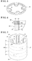
Fig. 3 ] is a perspective view of a housing main body where a hard layer is formed. - [
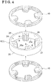
Fig. 4 ] is a perspective view of the housing main body and a covering member. - [
Fig. 5 ] is a perspective view of a covering member according to another embodiment. - [
Fig. 6 ] is a partial cross-sectional view illustrating a state where the covering member is provided at the housing main body. - [
Fig. 7 ] is a perspective view of a cylinder member. - As illustrated in
Fig. 1 , a valve opening/closing timing control device includes a housing 1 (example of a drive side rotational body) rotating synchronously with a crankshaft E1 of an engine E and an inner rotor 3 (example of a driven side rotational body) housed within thehousing 1 and rotating integrally with acamshaft 2 of the engine E. Thehousing 1 and theinner rotor 3 are arranged on an identical axis X. - As illustrated in
Figs. 1 and2 , thehousing 1 includes a front plate 4 (example of a cover plate) provided at a front side, i.e., at an opposite side from thecamshaft 2, a rear plate 5 (example of the cover plate) provided at a rear side, i.e., at a side where thecamshaft 2 is provided, and an outer rotor 6 (example of a housing main body) disposed between thefront plate 4 and therear plate 5. A sprocket is formed at an outer peripheral portion of therear plate 5. Thefront plate 4, therear plate 5, and theouter rotor 6 are fixed together by a screw. Theouter rotor 6 includes an opening 24 (seeFig. 3 ) that opens to at least one side in a direction along the rotational axis X. Thefront plate 4 and therear plate 5 occlude theopening 24 by making contact with respective end surfaces 25 of theopening 24 of theouter rotor 6. The sprocket may not be formed at the outer peripheral portion of therear plate 5 and may be formed at an outer peripheral portion of theouter rotor 6. - In a case where the crankshaft E1 is driven to rotate, a rotation driving force thereof is transmitted to the
rear plate 5 via a power transmission member E2. Theouter rotor 6 is then driven to rotate in a rotation direction S (seeFig. 2 ). In association with the rotational driving of theouter rotor 6, theinner rotor 3 is driven to rotate in the rotation direction S, which causes thecamshaft 2 to rotate to thereby press down an intake valve (not illustrated) of the engine by a cam (not illustrated) provided at thecamshaft 2. - As illustrated in
Fig. 2 , plural protrudingportions 8 protruding to a radially inner side are formed at an inner peripheral portion of theouter rotor 6. The protrudingportions 8 are arranged to be spaced away from one another along the rotation direction S.Plural partition portions 9 protruding to a radially outer side are formed at an outer peripheral portion of theinner rotor 3. Thepartition portions 9 are arranged to be spaced away from one another along the rotation direction S in the same way as the protrudingportions 8. A void between an innerperipheral surface 26 of theouter rotor 6 and theinner rotor 3 is divided into plural hydraulic chambers. The hydraulic chambers are divided intoadvance chambers 11 andretardation chambers 12 by thepartition portions 9. In order to inhibit leakage of engine oil between theadvance chambers 11 and theretardation chambers 12, seal members SE are provided at positions at the protrudingportions 8 facing an outer peripheral surface of theinner rotor 3 and at positions at thepartition portions 9 facing an inner peripheral surface of theouter rotor 6. - The
outer rotor 6 is formed of sintered metal of stainless, iron, copper alloy and the like, aluminum, or aluminum alloy, for example. In theouter rotor 6, as illustrated inFig. 3 , ahard layer 30 is formed at the innerperipheral surface 26 in the surface of theouter rotor 6 excluding the end surfaces 25 of theopening 24. - The
hard layer 30 is formed of fluorine resin such as polytetrafluoroethylene resin (PTFE), for example, or hard resin such as polyphenylene sulfide resin (PPS), polyimide resin (PI), polyamide-imide resin (PAI), polyamide resin (PA), fully aromatic polyester resin (ARPES), polyether ketone resin (PEK), and polyetherether ketone resin (PEEK), for example. As a formation method of thehard layer 30, an electrostatic powder coating process, a derivative coating process, a fluidization dip coating process, a spray coating process, a brushing process or the like may be employed. Theouter rotor 6 may be formed of aluminum material and an alumite layer may be formed as thehard layer 30 at the innerperipheral surface 26. - Accordingly, the
hard layer 30 formed at least at the innerperipheral surface 26 in theouter rotor 6 is provided to thereby enhance abrasion resistance of theouter rotor 6 in a case where a portion of theinner rotor 3 slides on theouter rotor 6. Meanwhile, thehard layer 30 is inhibited from being formed at the end surfaces 25 of theopening 24 of theouter rotor 6 so that adhesion properties between theend surface 25 of theopening 24 and thefront plate 4 are enhanced at the time of assembly of thehousing 1. Thus, leakage of hydraulic oil that fills theadvance chambers 11 or theretardation chambers 12 is restrained, which may obtain the valve opening/closing timing control device with improved operation responsiveness. - As illustrated in
Figs. 1 and2 , anadvance passage 13 and aretardation passage 14 are formed at inner portions of theinner rotor 3, aconnection member 22 and thecamshaft 2. Theadvance passage 13 connects each of theadvance chambers 11 and a supply and discharge mechanism KK which conducts and blocks supply and discharge of engine oil. Theretardation passage 14 connects each of theretardation chambers 12 and the supply and discharge mechanism KK. - The supply and discharge mechanism KK includes an oil pan, an oil motor, a fluid control valve OCV which conducts and blocks supply and discharge of engine oil relative to the
advance passage 13 and theretardation passage 14, and an electronic control unit ECU controlling an operation of the fluid control valve OCV. By the control of the supply and discharge mechanism KK, a relative rotational phase between theinner rotor 3 and theouter rotor 6 is displaced in an advance direction (direction of an arrow S1 inFig. 2 ) or in a retardation direction (direction of an arrow S2 inFig. 2 ) or is maintained at any phase. - A lock mechanism RK locks the
inner rotor 3 and theouter rotor 6 at a predetermined relative rotational phase. The lock mechanism RK is formed by alock member 16 including an end portion which is projectable and retractable in the direction along the rotational axis X relative to a recess portion (not illustrated) formed at therear plate 5, thelock member 16 being provided at one of thepartition portions 9 of theinner rotor 3. In addition, a hydraulic chamber (not illustrated) is provided for generating a the surfa to thelock member 16. The aforementioned hydraulic chamber is in communication with theadvance passage 13 or theretardation passage 14. According to the aforementioned configuration, the lock mechanism RK is switched to a lock state where the end portion of thelock member 16 enters the recess portion by receiving a biasing force of a biasing member (not illustrated) such as a compression spring, for example. In addition, the lock mechanism RK is switched to a lock release state where the end portion removes from the recess portion towards theinner rotor 3 against the biasing force of the biasing member. - For example, in a case where the outer rotor 6 (example of the housing main body) constituting the
housing 1 is formed of aluminum material, the alumite treatment is performed on the innerperipheral surface 26 to form thehard layer 30. In order to form such thehard layer 30, first, the end surfaces 25, 25 at opposed sides of theopening 24 of theouter rotor 6 are covered by coveringmembers 40, 40 (seeFig. 4 ). Each of the coveringmembers 40 is formed by a hard rubber member or a copper plate, for example, so as to extend along theopening 24 of theouter rotor 6. The coveringmember 40 illustrated inFig. 4 includes substantially the same configuration as theend surface 25 of theopening 24 of theouter rotor 6, however, any configuration of the coveringmember 40 is acceptable as long as the coveringmember 40 fully covers theend surface 25 of theopening 24 of theouter rotor 6. - After the end surfaces 25, 25 of the
opening 24 are covered by the coveringmembers 40, 40 (seeFig. 4 ), thehard layer 30 is formed at least at the innerperipheral surface 26 in a region of the surface of theouter rotor 6 excluding the end surfaces 25 of theopening 24. As for the alumite treatment, a general method is employed except for the usage of the coveringmembers hard layer 30 may be formed at an outerperipheral surface 27 along with the innerperipheral surface 26, instead of being formed only at the innerperipheral surface 26. After thehard layer 30 is formed at theouter rotor 6, each of the coveringmembers 40 is removed from each of the end surfaces 25 of theopening 24 so that thefront plate 4 and therear plate 5 are mounted to the end surfaces 25, 25 of theopening 24 to complete thehousing 1. - In the
housing 1, if theouter rotor 6 and one of thefront plate 4 and therear plate 5 are integrally formed, the coveringmember 40 is arranged only at theend surface 25 at one side of theopening 24. - Accordingly, the
hard layer 30 is formed at the innerperipheral surface 26 of theouter rotor 6 to thereby improve the abrasion resistance of theouter rotor 6. Meanwhile, thehard layer 30 is inhibited from being formed at the end surfaces 25 of theopening 24 of theouter rotor 6. Thus, in a case where thefront plate 4 is mounted to theend surface 25 of theopening 24 of theouter rotor 6, the front surface of theend surface 25 of theopening 24 is likely to make close contact with thefront plate 4. As a result, leakage of hydraulic oil that fills theadvance chambers 11 or theretardation chambers 12 is restrained, which obtains the valve opening/closing timing control device with the improved operation responsiveness. - In addition, in the present production method, the end surfaces 25 of the
opening 24 are covered at the time of forming thehard layer 30 at the innerperipheral surface 26. Thus, it is not required to perform a specific process on the end surfaces 25 of theopening 24 after the hardening process of the innerperipheral surface 26 is completed. Thus, the housing member including an expected performance may be effectively obtained. - In order to bring the
hard layer 30 formed at the innerperipheral surface 26 to securely make contact with a portion of theinner rotor 3 over the entire width thereof, the sound alumite layer (hard layer) 30 is necessarily formed up to a boundary position relative to each of the end surfaces 25 of theopening 24. Nevertheless, in a case where the rubber member (example of the covering member) 40 is pressed against theend surface 25 of theopening 24 of theouter rotor 6, for example, therubber member 40 is comparatively compressively deformed. A portion of therubber member 40 protruding from anedge portion 25a of theend surface 25 of theopening 24 is pushed out to a center side of the innerperipheral surface 26. In a case where such push-out of therubber member 40 increases, a void where the alumite layer (hard layer) 30 should grow is blocked by therubber member 40 at the boundary position of the innerperipheral surface 26 relative to theend surface 25 of theopening 24, which makes the sound alumite layer (hard layer) 30 difficult to be formed. - Then, as illustrated in
Figs. 5 and 6 , therubber member 40 covering each of the end surfaces 25 of theopening 24 is constituted by two difference types ofrubber materials rubber member 40, therubber material 41 including a high hardness is disposed at a portion making contact with theedge portion 25a in the vicinity of the innerperipheral surface 26 of theouter rotor 6 among edge portions of theend surface 25 of theopening 24 and therubber material 42 including a low hardness is disposed at a portion facing other than theedge portion 25a of theend surface 25 of theopening 24. - As mentioned above, in the
rubber member 40, therubber material 41 that makes contact with theedge portion 25a of theend surface 25 of theopening 24 includes a high hardness to thereby reduce the push-out of therubber material 41 to the center side of the innerperipheral surface 26. Accordingly, the alumite layer (hard layer) 30 may grow soundly up to the boundary position of the innerperipheral surface 26 relative to theend surface 25 of theopening 24 in the innerperipheral surface 26. The improvedhard layer 30 may be formed at the innerperipheral surface 26 of theouter rotor 6 over the direction of the rotational axis X. - That is, the
hard layer 30 at the innerperipheral surface 26 is formed up to the same position as theend surface 25 of theopening 24 in the axis direction of theouter rotor 6. Accordingly, a pressure-receiving area of thehard layer 30 relative to thepartition portion 9 of theinner rotor 3 increases, which increases the abrasion resistance of thehard layer 30. In addition, because thepartition portion 9 of theinner rotor 3 makes contact with thehard layer 30 which is formed up to the same position as theend surface 25 of theopening 24, leakage of hydraulic oil may be restrained. -
- (1) In the aforementioned embodiment, an example where the end surfaces 25 of the
opening 24 of the singleouter rotor 6 are covered by the coveringmembers 40 is explained. As illustrated inFig. 7 , pluralouter rotors 6 may be produced by using anelongated cylinder member 60. Thecylinder member 60 may be formed by extrusion molding, for example. Plural cutting-plane lines C are provided at an outer peripheral surface of thecylinder member 60. The cutting-plane lines C are specified depending on a thickness dimension along the axis direction of theouter rotor 6. In order to produce theouter rotors 6, thehard layer 30 is formed at only the innerperipheral surface 26 of thecylinder member 60 or at both the innerperipheral surface 26 and the outerperipheral surface 27, and thereafter thecylinder member 60 is cut along the cutting-plane lines C. The hard layer formed at theend surface 25 at each end of theopening 24 of thecylinder member 60 is scraped by performing a cutting process.
Accordingly, the pluralouter rotors 6 at each of which thehard layer 30 is inhibited from being formed at theend surface 25 of theopening 24 may be produced from thecylinder member 60. Theouter rotor 6 that is produced from a portion of thecylinder member 60 in the vicinity of a center thereof includes the end surfaces 25 of theopening 24 where thehard layer 30 is not formed, only by the cutting along the cutting-plane lines C. Accordingly, the pluralouter rotors 6 may be manufactured by covering the end surfaces 25 at the opposed sides of theopening 24 of thecylinder member 60, which leads to an effective production of theouter rotors 6. - (2) In the aforementioned embodiment, an example where the
housing 1 is constituted by three members of theouter rotor 6, thefront plate 4 and therear plate 5 is explained. Alternatively, thehousing 1 may be constituted by theouter rotor 6 at which one of thefront plate 4 and therear plate 5 is integrally formed. - (3) In the aforementioned embodiment, an example where the
rubber member 40 is constituted by two types of therubber materials rubber member 40 may be constituted by three or more than three types of rubber materials including different hardness as long as the push-out of the rubber material to the center side of the innerperipheral surface 26 from theend surface 25 of theopening 24 is reduced. - The present invention is applicable to a valve opening/closing timing control device of an internal combustion engine for an automobile or others.
-
- 1
- housing (drive side rotational body)
- 2
- camshaft
- 3
- inner rotor (driven side rotational body)
- 4
- front plate (cover plate)
- 5
- rear plate (cover plate)
- 6
- outer rotor (housing main body)
- 11
- advance chamber
- 12
- retardation chamber
- 24
- opening
- 25
- end surface
- 25a
- edge portion
- 26
- inner peripheral surface
- 30
- hard layer
- 40
- covering member
- 41
- rubber material including high hardness
- 42
- rubber material including low hardness
- 60
- cylinder member
- X
- rotational axis
Claims (5)
- A valve opening/closing timing control device comprising:a drive side rotational body including a housing main body that includes an opening which opens to at least one side in a direction along a rotational axis and a cover plate closing the opening by making contact with an end surface of the opening, the drive side rotational body rotating synchronously with a crankshaft; anda driven side rotational body housed within the drive side rotational body and defining an advance chamber and a retardation chamber relative to an inner peripheral surface of the housing main body, the driven side rotational body rotating integrally with a camshaft and coaxially with the rotational axis, whereinthe housing main body includes a hard layer formed at least at the inner peripheral surface of the housing main body in a surface thereof excluding the end surface of the opening.
- The valve opening/closing timing control device according to claim 1, wherein the housing main body is in an annular form and the hard layer at the inner peripheral surface is formed up to the same position as the end surface of the opening in an axis direction of the housing main body.
- A production method for a drive side rotational body of a valve opening/closing timing control device, the valve opening/closing timing control device including:a drive side rotational body including at least one housing main body that includes an opening which opens to at least one side in a direction along a rotational axis and a cover plate closing the opening by making contact with an end surface of the opening, the drive side rotational body rotating synchronously with a crankshaft; anda driven side rotational body housed within the drive side rotational body and defining an advance chamber and a retardation chamber relative to an inner peripheral surface of the housing main body, the driven side rotational body rotating integrally with a camshaft and coaxially with the rotational axis,the production method comprising forming a hard layer at least at the inner peripheral surface of the housing main body in a region thereof excluding the end surface of the opening.
- The production method for the drive side rotational body according to claim 3, wherein
the housing main body is made of an aluminum material and the end surface of the opening of the housing main body is covered by a rubber member constituted by at least two types of rubber materials including different hardness,
the rubber material including a high hardness in the rubber member is disposed at a portion making contact with an edge portion of the end surface of the opening in a vicinity of the inner peripheral surface of the housing main body among edge portions of the end surface of the opening. - The production method for the drive side rotational body according to claim 3, wherein the hard layer is formed at least at an inner peripheral surface of a cylinder body among the inner peripheral surface and an outer peripheral surface of the cylinder body,
the cylinder body is cut along a cutting-plane line which is specified at the outer peripheral surface depending on a thickness dimension of the housing main body to form the drive side rotational body.
Applications Claiming Priority (2)
| Application Number | Priority Date | Filing Date | Title |
|---|---|---|---|
| JP2013082178A JP6048887B2 (en) | 2013-04-10 | 2013-04-10 | Method for manufacturing drive side rotor in valve timing control device |
| PCT/JP2014/056960 WO2014167945A1 (en) | 2013-04-10 | 2014-03-14 | Valve-opening/closing-timing control device, and production method for drive-side rotational body of valve-opening/closing-timing control device |
Publications (3)
| Publication Number | Publication Date |
|---|---|
| EP2985429A1 true EP2985429A1 (en) | 2016-02-17 |
| EP2985429A4 EP2985429A4 (en) | 2016-05-18 |
| EP2985429B1 EP2985429B1 (en) | 2017-04-19 |
Family
ID=51689359
Family Applications (1)
| Application Number | Title | Priority Date | Filing Date |
|---|---|---|---|
| EP14782134.2A Not-in-force EP2985429B1 (en) | 2013-04-10 | 2014-03-14 | Production method for drive-side rotational body of valve-opening/closing-timing control device |
Country Status (6)
| Country | Link |
|---|---|
| US (1) | US20160017772A1 (en) |
| EP (1) | EP2985429B1 (en) |
| JP (1) | JP6048887B2 (en) |
| KR (1) | KR101647350B1 (en) |
| CN (1) | CN105008680A (en) |
| WO (1) | WO2014167945A1 (en) |
Cited By (1)
| Publication number | Priority date | Publication date | Assignee | Title |
|---|---|---|---|---|
| DE102018101979A1 (en) | 2018-01-30 | 2019-08-01 | Schaeffler Technologies AG & Co. KG | Hydraulic camshaft adjuster |
Families Citing this family (3)
| Publication number | Priority date | Publication date | Assignee | Title |
|---|---|---|---|---|
| JP6524819B2 (en) * | 2015-06-29 | 2019-06-05 | アイシン精機株式会社 | Valve timing control device |
| US10302184B2 (en) * | 2016-04-01 | 2019-05-28 | Shimano Inc. | Bicycle component, bicycle sprocket, and bicycle composite sprocket |
| WO2021014533A1 (en) * | 2019-07-22 | 2021-01-28 | 三菱電機株式会社 | Reduction gear and variable valve timing device |
Family Cites Families (9)
| Publication number | Priority date | Publication date | Assignee | Title |
|---|---|---|---|---|
| JP3637148B2 (en) * | 1996-04-26 | 2005-04-13 | 三菱化学株式会社 | SUBSTRATE FOR ELECTROPHOTOGRAPHIC PHOTOSENSOR, PROCESS FOR PRODUCING THE SAME, AND ELECTROPHOTOGRAPHIC PHOTOSENSITIVE |
| JP2001132415A (en) | 1999-10-29 | 2001-05-15 | Ntn Corp | Valve timing regulating device for engine |
| JP4305823B2 (en) * | 2003-02-17 | 2009-07-29 | スズキ株式会社 | Surface treatment masking method and apparatus |
| JP5397082B2 (en) * | 2009-01-15 | 2014-01-22 | リコーイメージング株式会社 | Surface processing method of lens frame member |
| JP5179405B2 (en) * | 2009-02-27 | 2013-04-10 | 日立オートモティブシステムズ株式会社 | Valve timing control device for internal combustion engine |
| US8171904B2 (en) * | 2009-02-27 | 2012-05-08 | Hitachi Automotive Systems, Inc. | Valve timing control apparatus for internal combustion engine |
| CN201801618U (en) * | 2010-07-12 | 2011-04-20 | 成都银河动力股份有限公司 | Hard anode oxidation fixture for aluminum piston of internal combustion engine |
| CN102562206A (en) * | 2012-01-18 | 2012-07-11 | 芜湖杰锋汽车动力系统有限公司 | Variable valve timing distribution regulating device and method for improving mechanical property of variable valve timing distribution regulating device |
| JP5466281B2 (en) * | 2012-10-31 | 2014-04-09 | 日立オートモティブシステムズ株式会社 | Valve timing control device for internal combustion engine |
-
2013
- 2013-04-10 JP JP2013082178A patent/JP6048887B2/en not_active Expired - Fee Related
-
2014
- 2014-03-14 WO PCT/JP2014/056960 patent/WO2014167945A1/en not_active Ceased
- 2014-03-14 KR KR1020157023965A patent/KR101647350B1/en not_active Expired - Fee Related
- 2014-03-14 EP EP14782134.2A patent/EP2985429B1/en not_active Not-in-force
- 2014-03-14 CN CN201480011351.0A patent/CN105008680A/en active Pending
- 2014-03-14 US US14/774,067 patent/US20160017772A1/en not_active Abandoned
Cited By (1)
| Publication number | Priority date | Publication date | Assignee | Title |
|---|---|---|---|---|
| DE102018101979A1 (en) | 2018-01-30 | 2019-08-01 | Schaeffler Technologies AG & Co. KG | Hydraulic camshaft adjuster |
Also Published As
| Publication number | Publication date |
|---|---|
| JP2014206047A (en) | 2014-10-30 |
| US20160017772A1 (en) | 2016-01-21 |
| EP2985429B1 (en) | 2017-04-19 |
| EP2985429A4 (en) | 2016-05-18 |
| WO2014167945A1 (en) | 2014-10-16 |
| JP6048887B2 (en) | 2016-12-21 |
| KR20150110817A (en) | 2015-10-02 |
| CN105008680A (en) | 2015-10-28 |
| KR101647350B1 (en) | 2016-08-23 |
Similar Documents
| Publication | Publication Date | Title |
|---|---|---|
| EP2985429B1 (en) | Production method for drive-side rotational body of valve-opening/closing-timing control device | |
| US20020038501A1 (en) | Method for manufacturing valve timing adjusting apparatus | |
| JP7074102B2 (en) | Hydraulic oil control valve and valve timing adjuster | |
| CN113614337A (en) | Working oil control valve and valve timing adjusting device | |
| EP3165723A1 (en) | Valve opening and closing timing control apparatus | |
| CN102312689B (en) | Variable valve timing control apparatus | |
| US9689285B2 (en) | Solenoid valve for variable valve timing control devices, and variable valve timing control system | |
| JP5146550B2 (en) | Valve timing adjustment device | |
| CN113614333A (en) | Working oil control valve and valve timing adjusting device | |
| CN105793527A (en) | Valve timing control device for internal combustion engine | |
| US9951660B2 (en) | Valve timing control device for internal combustion engine, and fastening structure | |
| US20110107991A1 (en) | Valve timing adjuster | |
| US20200095905A1 (en) | Green Compact of a Stator-Cover Unit | |
| CN105745405B (en) | valve timing control device | |
| US6920853B2 (en) | Variable valve timing control device | |
| US6935291B2 (en) | Variable valve timing controller | |
| US20150144084A1 (en) | Valve timing adjusting apparatus | |
| US20150027393A1 (en) | Valve timing control device | |
| WO2017002652A1 (en) | Valve opening/closing timing control device | |
| JP5682862B2 (en) | Valve timing adjustment device | |
| US9995185B2 (en) | Valve timing control device for internal combustion engine | |
| WO2020054242A1 (en) | Valve timing control device for internal combustion engine, and method for manufacturing same | |
| WO2021125073A1 (en) | Internal combustion engine valve timing control device | |
| JP2011106288A (en) | Valve timing adjustment device | |
| JP2016183561A (en) | Valve timing adjusting device |
Legal Events
| Date | Code | Title | Description |
|---|---|---|---|
| PUAI | Public reference made under article 153(3) epc to a published international application that has entered the european phase |
Free format text: ORIGINAL CODE: 0009012 |
|
| 17P | Request for examination filed |
Effective date: 20150828 |
|
| AK | Designated contracting states |
Kind code of ref document: A1 Designated state(s): AL AT BE BG CH CY CZ DE DK EE ES FI FR GB GR HR HU IE IS IT LI LT LU LV MC MK MT NL NO PL PT RO RS SE SI SK SM TR |
|
| AX | Request for extension of the european patent |
Extension state: BA ME |
|
| A4 | Supplementary search report drawn up and despatched |
Effective date: 20160418 |
|
| RIC1 | Information provided on ipc code assigned before grant |
Ipc: C25D 11/02 20060101ALI20160412BHEP Ipc: C25D 11/04 20060101ALI20160412BHEP Ipc: F01L 1/344 20060101ALI20160412BHEP Ipc: F01L 1/356 20060101AFI20160412BHEP |
|
| DAX | Request for extension of the european patent (deleted) | ||
| RIC1 | Information provided on ipc code assigned before grant |
Ipc: C25D 11/02 20060101ALI20161017BHEP Ipc: F01L 1/356 20060101AFI20161017BHEP Ipc: C25D 11/04 20060101ALI20161017BHEP Ipc: F01L 1/344 20060101ALI20161017BHEP |
|
| GRAP | Despatch of communication of intention to grant a patent |
Free format text: ORIGINAL CODE: EPIDOSNIGR1 |
|
| INTG | Intention to grant announced |
Effective date: 20161207 |
|
| GRAS | Grant fee paid |
Free format text: ORIGINAL CODE: EPIDOSNIGR3 |
|
| GRAA | (expected) grant |
Free format text: ORIGINAL CODE: 0009210 |
|
| AK | Designated contracting states |
Kind code of ref document: B1 Designated state(s): AL AT BE BG CH CY CZ DE DK EE ES FI FR GB GR HR HU IE IS IT LI LT LU LV MC MK MT NL NO PL PT RO RS SE SI SK SM TR |
|
| REG | Reference to a national code |
Ref country code: GB Ref legal event code: FG4D |
|
| REG | Reference to a national code |
Ref country code: CH Ref legal event code: EP |
|
| REG | Reference to a national code |
Ref country code: AT Ref legal event code: REF Ref document number: 886184 Country of ref document: AT Kind code of ref document: T Effective date: 20170515 |
|
| REG | Reference to a national code |
Ref country code: IE Ref legal event code: FG4D |
|
| REG | Reference to a national code |
Ref country code: DE Ref legal event code: R096 Ref document number: 602014008905 Country of ref document: DE |
|
| REG | Reference to a national code |
Ref country code: NL Ref legal event code: MP Effective date: 20170419 |
|
| REG | Reference to a national code |
Ref country code: LT Ref legal event code: MG4D |
|
| REG | Reference to a national code |
Ref country code: AT Ref legal event code: MK05 Ref document number: 886184 Country of ref document: AT Kind code of ref document: T Effective date: 20170419 |
|
| PG25 | Lapsed in a contracting state [announced via postgrant information from national office to epo] |
Ref country code: NL Free format text: LAPSE BECAUSE OF FAILURE TO SUBMIT A TRANSLATION OF THE DESCRIPTION OR TO PAY THE FEE WITHIN THE PRESCRIBED TIME-LIMIT Effective date: 20170419 |
|
| PG25 | Lapsed in a contracting state [announced via postgrant information from national office to epo] |
Ref country code: GR Free format text: LAPSE BECAUSE OF FAILURE TO SUBMIT A TRANSLATION OF THE DESCRIPTION OR TO PAY THE FEE WITHIN THE PRESCRIBED TIME-LIMIT Effective date: 20170720 Ref country code: AT Free format text: LAPSE BECAUSE OF FAILURE TO SUBMIT A TRANSLATION OF THE DESCRIPTION OR TO PAY THE FEE WITHIN THE PRESCRIBED TIME-LIMIT Effective date: 20170419 Ref country code: HR Free format text: LAPSE BECAUSE OF FAILURE TO SUBMIT A TRANSLATION OF THE DESCRIPTION OR TO PAY THE FEE WITHIN THE PRESCRIBED TIME-LIMIT Effective date: 20170419 Ref country code: NO Free format text: LAPSE BECAUSE OF FAILURE TO SUBMIT A TRANSLATION OF THE DESCRIPTION OR TO PAY THE FEE WITHIN THE PRESCRIBED TIME-LIMIT Effective date: 20170719 Ref country code: FI Free format text: LAPSE BECAUSE OF FAILURE TO SUBMIT A TRANSLATION OF THE DESCRIPTION OR TO PAY THE FEE WITHIN THE PRESCRIBED TIME-LIMIT Effective date: 20170419 Ref country code: ES Free format text: LAPSE BECAUSE OF FAILURE TO SUBMIT A TRANSLATION OF THE DESCRIPTION OR TO PAY THE FEE WITHIN THE PRESCRIBED TIME-LIMIT Effective date: 20170419 Ref country code: LT Free format text: LAPSE BECAUSE OF FAILURE TO SUBMIT A TRANSLATION OF THE DESCRIPTION OR TO PAY THE FEE WITHIN THE PRESCRIBED TIME-LIMIT Effective date: 20170419 |
|
| PG25 | Lapsed in a contracting state [announced via postgrant information from national office to epo] |
Ref country code: BG Free format text: LAPSE BECAUSE OF FAILURE TO SUBMIT A TRANSLATION OF THE DESCRIPTION OR TO PAY THE FEE WITHIN THE PRESCRIBED TIME-LIMIT Effective date: 20170719 Ref country code: PL Free format text: LAPSE BECAUSE OF FAILURE TO SUBMIT A TRANSLATION OF THE DESCRIPTION OR TO PAY THE FEE WITHIN THE PRESCRIBED TIME-LIMIT Effective date: 20170419 Ref country code: LV Free format text: LAPSE BECAUSE OF FAILURE TO SUBMIT A TRANSLATION OF THE DESCRIPTION OR TO PAY THE FEE WITHIN THE PRESCRIBED TIME-LIMIT Effective date: 20170419 Ref country code: IS Free format text: LAPSE BECAUSE OF FAILURE TO SUBMIT A TRANSLATION OF THE DESCRIPTION OR TO PAY THE FEE WITHIN THE PRESCRIBED TIME-LIMIT Effective date: 20170819 Ref country code: RS Free format text: LAPSE BECAUSE OF FAILURE TO SUBMIT A TRANSLATION OF THE DESCRIPTION OR TO PAY THE FEE WITHIN THE PRESCRIBED TIME-LIMIT Effective date: 20170419 Ref country code: SE Free format text: LAPSE BECAUSE OF FAILURE TO SUBMIT A TRANSLATION OF THE DESCRIPTION OR TO PAY THE FEE WITHIN THE PRESCRIBED TIME-LIMIT Effective date: 20170419 |
|
| REG | Reference to a national code |
Ref country code: DE Ref legal event code: R097 Ref document number: 602014008905 Country of ref document: DE |
|
| PG25 | Lapsed in a contracting state [announced via postgrant information from national office to epo] |
Ref country code: CZ Free format text: LAPSE BECAUSE OF FAILURE TO SUBMIT A TRANSLATION OF THE DESCRIPTION OR TO PAY THE FEE WITHIN THE PRESCRIBED TIME-LIMIT Effective date: 20170419 Ref country code: RO Free format text: LAPSE BECAUSE OF FAILURE TO SUBMIT A TRANSLATION OF THE DESCRIPTION OR TO PAY THE FEE WITHIN THE PRESCRIBED TIME-LIMIT Effective date: 20170419 Ref country code: DK Free format text: LAPSE BECAUSE OF FAILURE TO SUBMIT A TRANSLATION OF THE DESCRIPTION OR TO PAY THE FEE WITHIN THE PRESCRIBED TIME-LIMIT Effective date: 20170419 Ref country code: SK Free format text: LAPSE BECAUSE OF FAILURE TO SUBMIT A TRANSLATION OF THE DESCRIPTION OR TO PAY THE FEE WITHIN THE PRESCRIBED TIME-LIMIT Effective date: 20170419 Ref country code: EE Free format text: LAPSE BECAUSE OF FAILURE TO SUBMIT A TRANSLATION OF THE DESCRIPTION OR TO PAY THE FEE WITHIN THE PRESCRIBED TIME-LIMIT Effective date: 20170419 |
|
| PLBE | No opposition filed within time limit |
Free format text: ORIGINAL CODE: 0009261 |
|
| STAA | Information on the status of an ep patent application or granted ep patent |
Free format text: STATUS: NO OPPOSITION FILED WITHIN TIME LIMIT |
|
| PG25 | Lapsed in a contracting state [announced via postgrant information from national office to epo] |
Ref country code: IT Free format text: LAPSE BECAUSE OF FAILURE TO SUBMIT A TRANSLATION OF THE DESCRIPTION OR TO PAY THE FEE WITHIN THE PRESCRIBED TIME-LIMIT Effective date: 20170419 Ref country code: SM Free format text: LAPSE BECAUSE OF FAILURE TO SUBMIT A TRANSLATION OF THE DESCRIPTION OR TO PAY THE FEE WITHIN THE PRESCRIBED TIME-LIMIT Effective date: 20170419 |
|
| 26N | No opposition filed |
Effective date: 20180122 |
|
| PG25 | Lapsed in a contracting state [announced via postgrant information from national office to epo] |
Ref country code: SI Free format text: LAPSE BECAUSE OF FAILURE TO SUBMIT A TRANSLATION OF THE DESCRIPTION OR TO PAY THE FEE WITHIN THE PRESCRIBED TIME-LIMIT Effective date: 20170419 |
|
| REG | Reference to a national code |
Ref country code: DE Ref legal event code: R119 Ref document number: 602014008905 Country of ref document: DE |
|
| REG | Reference to a national code |
Ref country code: CH Ref legal event code: PL |
|
| GBPC | Gb: european patent ceased through non-payment of renewal fee |
Effective date: 20180314 |
|
| PG25 | Lapsed in a contracting state [announced via postgrant information from national office to epo] |
Ref country code: MC Free format text: LAPSE BECAUSE OF FAILURE TO SUBMIT A TRANSLATION OF THE DESCRIPTION OR TO PAY THE FEE WITHIN THE PRESCRIBED TIME-LIMIT Effective date: 20170419 |
|
| REG | Reference to a national code |
Ref country code: BE Ref legal event code: MM Effective date: 20180331 |
|
| REG | Reference to a national code |
Ref country code: IE Ref legal event code: MM4A |
|
| PG25 | Lapsed in a contracting state [announced via postgrant information from national office to epo] |
Ref country code: LU Free format text: LAPSE BECAUSE OF NON-PAYMENT OF DUE FEES Effective date: 20180314 |
|
| PG25 | Lapsed in a contracting state [announced via postgrant information from national office to epo] |
Ref country code: DE Free format text: LAPSE BECAUSE OF NON-PAYMENT OF DUE FEES Effective date: 20181002 Ref country code: IE Free format text: LAPSE BECAUSE OF NON-PAYMENT OF DUE FEES Effective date: 20180314 |
|
| PG25 | Lapsed in a contracting state [announced via postgrant information from national office to epo] |
Ref country code: CH Free format text: LAPSE BECAUSE OF NON-PAYMENT OF DUE FEES Effective date: 20180331 Ref country code: LI Free format text: LAPSE BECAUSE OF NON-PAYMENT OF DUE FEES Effective date: 20180331 Ref country code: GB Free format text: LAPSE BECAUSE OF NON-PAYMENT OF DUE FEES Effective date: 20180314 Ref country code: BE Free format text: LAPSE BECAUSE OF NON-PAYMENT OF DUE FEES Effective date: 20180331 |
|
| PG25 | Lapsed in a contracting state [announced via postgrant information from national office to epo] |
Ref country code: FR Free format text: LAPSE BECAUSE OF NON-PAYMENT OF DUE FEES Effective date: 20180331 |
|
| PG25 | Lapsed in a contracting state [announced via postgrant information from national office to epo] |
Ref country code: MT Free format text: LAPSE BECAUSE OF NON-PAYMENT OF DUE FEES Effective date: 20180314 |
|
| PG25 | Lapsed in a contracting state [announced via postgrant information from national office to epo] |
Ref country code: TR Free format text: LAPSE BECAUSE OF FAILURE TO SUBMIT A TRANSLATION OF THE DESCRIPTION OR TO PAY THE FEE WITHIN THE PRESCRIBED TIME-LIMIT Effective date: 20170419 |
|
| PG25 | Lapsed in a contracting state [announced via postgrant information from national office to epo] |
Ref country code: PT Free format text: LAPSE BECAUSE OF FAILURE TO SUBMIT A TRANSLATION OF THE DESCRIPTION OR TO PAY THE FEE WITHIN THE PRESCRIBED TIME-LIMIT Effective date: 20170419 |
|
| PG25 | Lapsed in a contracting state [announced via postgrant information from national office to epo] |
Ref country code: CY Free format text: LAPSE BECAUSE OF FAILURE TO SUBMIT A TRANSLATION OF THE DESCRIPTION OR TO PAY THE FEE WITHIN THE PRESCRIBED TIME-LIMIT Effective date: 20170419 Ref country code: MK Free format text: LAPSE BECAUSE OF NON-PAYMENT OF DUE FEES Effective date: 20170419 Ref country code: HU Free format text: LAPSE BECAUSE OF FAILURE TO SUBMIT A TRANSLATION OF THE DESCRIPTION OR TO PAY THE FEE WITHIN THE PRESCRIBED TIME-LIMIT; INVALID AB INITIO Effective date: 20140314 |
|
| PG25 | Lapsed in a contracting state [announced via postgrant information from national office to epo] |
Ref country code: AL Free format text: LAPSE BECAUSE OF FAILURE TO SUBMIT A TRANSLATION OF THE DESCRIPTION OR TO PAY THE FEE WITHIN THE PRESCRIBED TIME-LIMIT Effective date: 20170419 |