EP2985366A1 - Composite fan annulus filler with nanocrystalline coating - Google Patents
Composite fan annulus filler with nanocrystalline coating Download PDFInfo
- Publication number
- EP2985366A1 EP2985366A1 EP15180607.2A EP15180607A EP2985366A1 EP 2985366 A1 EP2985366 A1 EP 2985366A1 EP 15180607 A EP15180607 A EP 15180607A EP 2985366 A1 EP2985366 A1 EP 2985366A1
- Authority
- EP
- European Patent Office
- Prior art keywords
- coating
- filler
- annulus filler
- fan
- nanocrystalline
- Prior art date
- Legal status (The legal status is an assumption and is not a legal conclusion. Google has not performed a legal analysis and makes no representation as to the accuracy of the status listed.)
- Granted
Links
Images



Classifications
-
- F—MECHANICAL ENGINEERING; LIGHTING; HEATING; WEAPONS; BLASTING
- F01—MACHINES OR ENGINES IN GENERAL; ENGINE PLANTS IN GENERAL; STEAM ENGINES
- F01D—NON-POSITIVE DISPLACEMENT MACHINES OR ENGINES, e.g. STEAM TURBINES
- F01D11/00—Preventing or minimising internal leakage of working-fluid, e.g. between stages
- F01D11/005—Sealing means between non relatively rotating elements
- F01D11/006—Sealing the gap between rotor blades or blades and rotor
- F01D11/008—Sealing the gap between rotor blades or blades and rotor by spacer elements between the blades, e.g. independent interblade platforms
-
- C—CHEMISTRY; METALLURGY
- C25—ELECTROLYTIC OR ELECTROPHORETIC PROCESSES; APPARATUS THEREFOR
- C25D—PROCESSES FOR THE ELECTROLYTIC OR ELECTROPHORETIC PRODUCTION OF COATINGS; ELECTROFORMING; APPARATUS THEREFOR
- C25D1/00—Electroforming
- C25D1/02—Tubes; Rings; Hollow bodies
-
- C—CHEMISTRY; METALLURGY
- C25—ELECTROLYTIC OR ELECTROPHORETIC PROCESSES; APPARATUS THEREFOR
- C25D—PROCESSES FOR THE ELECTROLYTIC OR ELECTROPHORETIC PRODUCTION OF COATINGS; ELECTROFORMING; APPARATUS THEREFOR
- C25D1/00—Electroforming
- C25D1/08—Perforated or foraminous objects, e.g. sieves
-
- C—CHEMISTRY; METALLURGY
- C25—ELECTROLYTIC OR ELECTROPHORETIC PROCESSES; APPARATUS THEREFOR
- C25D—PROCESSES FOR THE ELECTROLYTIC OR ELECTROPHORETIC PRODUCTION OF COATINGS; ELECTROFORMING; APPARATUS THEREFOR
- C25D5/00—Electroplating characterised by the process; Pretreatment or after-treatment of workpieces
- C25D5/54—Electroplating of non-metallic surfaces
- C25D5/56—Electroplating of non-metallic surfaces of plastics
-
- F—MECHANICAL ENGINEERING; LIGHTING; HEATING; WEAPONS; BLASTING
- F01—MACHINES OR ENGINES IN GENERAL; ENGINE PLANTS IN GENERAL; STEAM ENGINES
- F01D—NON-POSITIVE DISPLACEMENT MACHINES OR ENGINES, e.g. STEAM TURBINES
- F01D25/00—Component parts, details, or accessories, not provided for in, or of interest apart from, other groups
- F01D25/28—Supporting or mounting arrangements, e.g. for turbine casing
-
- F—MECHANICAL ENGINEERING; LIGHTING; HEATING; WEAPONS; BLASTING
- F01—MACHINES OR ENGINES IN GENERAL; ENGINE PLANTS IN GENERAL; STEAM ENGINES
- F01D—NON-POSITIVE DISPLACEMENT MACHINES OR ENGINES, e.g. STEAM TURBINES
- F01D5/00—Blades; Blade-carrying members; Heating, heat-insulating, cooling or antivibration means on the blades or the members
- F01D5/12—Blades
- F01D5/28—Selecting particular materials; Particular measures relating thereto; Measures against erosion or corrosion
- F01D5/288—Protective coatings for blades
-
- F—MECHANICAL ENGINEERING; LIGHTING; HEATING; WEAPONS; BLASTING
- F05—INDEXING SCHEMES RELATING TO ENGINES OR PUMPS IN VARIOUS SUBCLASSES OF CLASSES F01-F04
- F05D—INDEXING SCHEME FOR ASPECTS RELATING TO NON-POSITIVE-DISPLACEMENT MACHINES OR ENGINES, GAS-TURBINES OR JET-PROPULSION PLANTS
- F05D2220/00—Application
- F05D2220/30—Application in turbines
-
- F—MECHANICAL ENGINEERING; LIGHTING; HEATING; WEAPONS; BLASTING
- F05—INDEXING SCHEMES RELATING TO ENGINES OR PUMPS IN VARIOUS SUBCLASSES OF CLASSES F01-F04
- F05D—INDEXING SCHEME FOR ASPECTS RELATING TO NON-POSITIVE-DISPLACEMENT MACHINES OR ENGINES, GAS-TURBINES OR JET-PROPULSION PLANTS
- F05D2220/00—Application
- F05D2220/30—Application in turbines
- F05D2220/32—Application in turbines in gas turbines
-
- F—MECHANICAL ENGINEERING; LIGHTING; HEATING; WEAPONS; BLASTING
- F05—INDEXING SCHEMES RELATING TO ENGINES OR PUMPS IN VARIOUS SUBCLASSES OF CLASSES F01-F04
- F05D—INDEXING SCHEME FOR ASPECTS RELATING TO NON-POSITIVE-DISPLACEMENT MACHINES OR ENGINES, GAS-TURBINES OR JET-PROPULSION PLANTS
- F05D2220/00—Application
- F05D2220/30—Application in turbines
- F05D2220/32—Application in turbines in gas turbines
- F05D2220/321—Application in turbines in gas turbines for a special turbine stage
- F05D2220/3212—Application in turbines in gas turbines for a special turbine stage the first stage of a turbine
-
- F—MECHANICAL ENGINEERING; LIGHTING; HEATING; WEAPONS; BLASTING
- F05—INDEXING SCHEMES RELATING TO ENGINES OR PUMPS IN VARIOUS SUBCLASSES OF CLASSES F01-F04
- F05D—INDEXING SCHEME FOR ASPECTS RELATING TO NON-POSITIVE-DISPLACEMENT MACHINES OR ENGINES, GAS-TURBINES OR JET-PROPULSION PLANTS
- F05D2220/00—Application
- F05D2220/30—Application in turbines
- F05D2220/32—Application in turbines in gas turbines
- F05D2220/323—Application in turbines in gas turbines for aircraft propulsion, e.g. jet engines
-
- F—MECHANICAL ENGINEERING; LIGHTING; HEATING; WEAPONS; BLASTING
- F05—INDEXING SCHEMES RELATING TO ENGINES OR PUMPS IN VARIOUS SUBCLASSES OF CLASSES F01-F04
- F05D—INDEXING SCHEME FOR ASPECTS RELATING TO NON-POSITIVE-DISPLACEMENT MACHINES OR ENGINES, GAS-TURBINES OR JET-PROPULSION PLANTS
- F05D2220/00—Application
- F05D2220/30—Application in turbines
- F05D2220/36—Application in turbines specially adapted for the fan of turbofan engines
-
- F—MECHANICAL ENGINEERING; LIGHTING; HEATING; WEAPONS; BLASTING
- F05—INDEXING SCHEMES RELATING TO ENGINES OR PUMPS IN VARIOUS SUBCLASSES OF CLASSES F01-F04
- F05D—INDEXING SCHEME FOR ASPECTS RELATING TO NON-POSITIVE-DISPLACEMENT MACHINES OR ENGINES, GAS-TURBINES OR JET-PROPULSION PLANTS
- F05D2230/00—Manufacture
- F05D2230/20—Manufacture essentially without removing material
-
- F—MECHANICAL ENGINEERING; LIGHTING; HEATING; WEAPONS; BLASTING
- F05—INDEXING SCHEMES RELATING TO ENGINES OR PUMPS IN VARIOUS SUBCLASSES OF CLASSES F01-F04
- F05D—INDEXING SCHEME FOR ASPECTS RELATING TO NON-POSITIVE-DISPLACEMENT MACHINES OR ENGINES, GAS-TURBINES OR JET-PROPULSION PLANTS
- F05D2230/00—Manufacture
- F05D2230/30—Manufacture with deposition of material
-
- F—MECHANICAL ENGINEERING; LIGHTING; HEATING; WEAPONS; BLASTING
- F05—INDEXING SCHEMES RELATING TO ENGINES OR PUMPS IN VARIOUS SUBCLASSES OF CLASSES F01-F04
- F05D—INDEXING SCHEME FOR ASPECTS RELATING TO NON-POSITIVE-DISPLACEMENT MACHINES OR ENGINES, GAS-TURBINES OR JET-PROPULSION PLANTS
- F05D2230/00—Manufacture
- F05D2230/30—Manufacture with deposition of material
- F05D2230/31—Layer deposition
-
- F—MECHANICAL ENGINEERING; LIGHTING; HEATING; WEAPONS; BLASTING
- F05—INDEXING SCHEMES RELATING TO ENGINES OR PUMPS IN VARIOUS SUBCLASSES OF CLASSES F01-F04
- F05D—INDEXING SCHEME FOR ASPECTS RELATING TO NON-POSITIVE-DISPLACEMENT MACHINES OR ENGINES, GAS-TURBINES OR JET-PROPULSION PLANTS
- F05D2230/00—Manufacture
- F05D2230/90—Coating; Surface treatment
-
- F—MECHANICAL ENGINEERING; LIGHTING; HEATING; WEAPONS; BLASTING
- F05—INDEXING SCHEMES RELATING TO ENGINES OR PUMPS IN VARIOUS SUBCLASSES OF CLASSES F01-F04
- F05D—INDEXING SCHEME FOR ASPECTS RELATING TO NON-POSITIVE-DISPLACEMENT MACHINES OR ENGINES, GAS-TURBINES OR JET-PROPULSION PLANTS
- F05D2240/00—Components
- F05D2240/20—Rotors
- F05D2240/24—Rotors for turbines
-
- F—MECHANICAL ENGINEERING; LIGHTING; HEATING; WEAPONS; BLASTING
- F05—INDEXING SCHEMES RELATING TO ENGINES OR PUMPS IN VARIOUS SUBCLASSES OF CLASSES F01-F04
- F05D—INDEXING SCHEME FOR ASPECTS RELATING TO NON-POSITIVE-DISPLACEMENT MACHINES OR ENGINES, GAS-TURBINES OR JET-PROPULSION PLANTS
- F05D2250/00—Geometry
- F05D2250/10—Two-dimensional
- F05D2250/19—Two-dimensional machined; miscellaneous
- F05D2250/191—Two-dimensional machined; miscellaneous perforated
-
- F—MECHANICAL ENGINEERING; LIGHTING; HEATING; WEAPONS; BLASTING
- F05—INDEXING SCHEMES RELATING TO ENGINES OR PUMPS IN VARIOUS SUBCLASSES OF CLASSES F01-F04
- F05D—INDEXING SCHEME FOR ASPECTS RELATING TO NON-POSITIVE-DISPLACEMENT MACHINES OR ENGINES, GAS-TURBINES OR JET-PROPULSION PLANTS
- F05D2300/00—Materials; Properties thereof
- F05D2300/10—Metals, alloys or intermetallic compounds
- F05D2300/17—Alloys
- F05D2300/177—Ni - Si alloys
-
- F—MECHANICAL ENGINEERING; LIGHTING; HEATING; WEAPONS; BLASTING
- F05—INDEXING SCHEMES RELATING TO ENGINES OR PUMPS IN VARIOUS SUBCLASSES OF CLASSES F01-F04
- F05D—INDEXING SCHEME FOR ASPECTS RELATING TO NON-POSITIVE-DISPLACEMENT MACHINES OR ENGINES, GAS-TURBINES OR JET-PROPULSION PLANTS
- F05D2300/00—Materials; Properties thereof
- F05D2300/40—Organic materials
- F05D2300/43—Synthetic polymers, e.g. plastics; Rubber
-
- F—MECHANICAL ENGINEERING; LIGHTING; HEATING; WEAPONS; BLASTING
- F05—INDEXING SCHEMES RELATING TO ENGINES OR PUMPS IN VARIOUS SUBCLASSES OF CLASSES F01-F04
- F05D—INDEXING SCHEME FOR ASPECTS RELATING TO NON-POSITIVE-DISPLACEMENT MACHINES OR ENGINES, GAS-TURBINES OR JET-PROPULSION PLANTS
- F05D2300/00—Materials; Properties thereof
- F05D2300/60—Properties or characteristics given to material by treatment or manufacturing
- F05D2300/611—Coating
-
- Y—GENERAL TAGGING OF NEW TECHNOLOGICAL DEVELOPMENTS; GENERAL TAGGING OF CROSS-SECTIONAL TECHNOLOGIES SPANNING OVER SEVERAL SECTIONS OF THE IPC; TECHNICAL SUBJECTS COVERED BY FORMER USPC CROSS-REFERENCE ART COLLECTIONS [XRACs] AND DIGESTS
- Y02—TECHNOLOGIES OR APPLICATIONS FOR MITIGATION OR ADAPTATION AGAINST CLIMATE CHANGE
- Y02T—CLIMATE CHANGE MITIGATION TECHNOLOGIES RELATED TO TRANSPORTATION
- Y02T50/00—Aeronautics or air transport
- Y02T50/60—Efficient propulsion technologies, e.g. for aircraft
Definitions
- the present disclosure relates to components for use in gas turbine engines, and particularly to annulus fillers for attachment to fan assemblies of the gas turbine engines.
- Gas turbine engines generally include a fan assembly and an engine core.
- the engine core includes a compressor section, a combustion section, and a turbine section including a plurality of rotation blades.
- the turbine section is driven by expansion of exhaust gases from the combustion section. The expanding exhaust gases rotate the turbine section, which is coupled to the fan assembly to drive rotation thereof.
- the fan assembly includes fan blades that are secured to a fan rotor. The fan blades are positioned circumferentially around a fan rotor and include fan annulus fillers located between the fan blades to assist in directing incoming air towards the fan blades.
- the present disclosure may comprise one or more of the following features and combinations thereof.
- the coating has a thickness of about 0.001 - 0.150 inches at all points along the exterior surface of the body.
- the polymer is selected from the group consisting of polyether ether ketone, acrylonitrile butadiene styrene, polyethylenimine, and Nylon GF.
- the nanocrystalline coating is nickel-based alloy coating.
- the body includes a plurality of bores defined therein and extending through the body between one portion of the exterior surface and another portion of the exterior surface.
- the coating is disposed within the bores to fill the bores and provide reinforcement pins that extend through the body.
- a method of making a fan annulus filler for mounting on a turbine engine includes forming an annulus filler body with a polymer and coating an exterior surface of the filler body with a nanocrystalline coating.
- forming the filler body is selected from the group consisting of injection molding and extruding.
- the polymer is selected from the group consisting of polyether ether ketone, acrylonitrile butadiene styrene, polyethylenimine, and Nylon GF.
- the nanocrystalline coating is nickel-based alloy coating.
- the method further includes, before coating the body, forming bores penetrating through the body.
- the step of coating the body includes filling the bores with the nanocrystalline coating to form reinforcement pins.
- the method further includes, after the step of coating the body, removing the polymer from the nanocrystalline coating to leave a shell of the nanocrystalline coating.
- a method of making a fan annulus filler for mounting on a turbine engine includes forming an filler body with a polymer, forming holes through the filler body, coating the filler body with a nanocrystalline coating, and removing the polymer from the filler body to form a shell made from the nanocrystalline coating that defines the annulus filler.
- the step of coating the filler body includes filling the holes with the nanocrystalline coating to form reinforcement pins.
- the step of removing the polymer comprises heating the annulus filler to a temperature of about 150 - 200 °F. In some embodiments, the step of removing the polymer comprises heating the annulus filler to a temperature of less than 400 °F.
- a melting point temperature of the polymer is lower than a melting point temperature of the coating.
- the step of coating includes applying the nanocrystalline coating to an exterior surface of the body to form a finished surface that requires no machining and forms a flow surface for use in the gas turbine engine.
- the method further includes coating the nanocrystalline coating with a rubberized coating to form a finished surface that requires no machining and forms a flow surface for use in the gas turbine engine.
- An illustrative gas turbine engine 10 is cut-away to show that the engine 10 includes a fan assembly 12 and an engine core 14 adapted to drive the fan assembly 12 as shown in Fig. 1 .
- the fan assembly 12 is adapted to push air to provide propulsion for use, for example by an aircraft.
- the engine core 14 includes a compressor 16, a combustor 18, and a turbine 20 as shown in Fig. 1 .
- the compressor 16 compresses and delivers air to the combustor 18.
- the combustor 18 mixes fuel with the compressed air received from the compressor 16 and ignites the fuel.
- the hot, high-pressure exhaust products of the combustion reaction in the combustor 18 are directed into the turbine 20 and the turbine 20 extracts work to drive the compressor 16 and the fan assembly 12.
- the fan assembly 12 includes a plurality of fan blades 24 attached at their radially inward ends to a fan rotor 15 as suggested in Fig. 1 .
- the fan blades 24 are illustratively distributed evenly around a circumference of the fan rotor 15.
- Each fan blade 24 is illustratively separated from the adjacent fan blade by a fan gap 26.
- a fan annulus filler 28 is illustratively disposed within each fan gap 26 to assist in directing incoming air towards the fan blades 24.
- the fan annulus filler 28 includes a coating 30 illustratively shown in Fig. 2 .
- the coating 30 is illustratively disposed on an all exterior portions of the annulus filler 28.
- the annulus filler 28 includes a flow surface 32 formed by the coating 30 on a top side thereof.
- the annulus filler 28 includes sides 29 each configured to receive a seal.
- the annulus fill includes a hook 34 illustratively extending from a bottom side for connection to the fan rotor 15 of the fan assembly 12.
- the annulus filler 28 includes a body 36.
- the body 36 is illustratively formed of a core material and includes an exterior surface 38 onto which the coating 30 is disposed as shown in Fig. 4 .
- the body 36 is illustratively formed of an injection molded polymer core 37.
- the body 36 may comprise one or more of polyether ether ketone (PEEK), acrylonitrile butadiene styrene (ABS), polyethylenimine (PEI), and nylon GF.
- the body 36 may be formed of a core which has a melting temperature of less than 200 °F, and in some embodiments, from about 150 to 200 °F.
- the coating 30 is illustratively formed of a nanocrystalline coating to form nanocrystalline structural plating.
- Nanocrystalline is defined as a polycrystalline having a grain size generally of 100 nm or less, but functional equivalents above the 100 nm threshold may suffice depending on their specific characteristics.
- the coating 30 is disposed with uniform thickness in the range of about 0.001 to 0.150 inches at all points on the exterior of the body 36. In some embodiments, the coating 30 may be disposed with a uniform thickness of about 0.001 to 0.125 at all points on the exterior of the body. In some embodiments, the coating 30 may have different thicknesses each from about 0.001 to 0.150 at different points on the exterior of the body 36 according to performance requirements. For example the coating 30 may be thicker along the flow surface 32 and/or along the hook 34 (i.e., the interface with the fan rotor 15) than along the other portions of the annulus filler 28. Thicker coating along the flow surface 32 and/or hook 34 may increase resistance to impacts during operation of the engine 10.
- the coating may include NANOVATE ® , for example one or more of N1210, N1010, N2020, and or N2025.
- the coating 30 may be disposed on the body 36 such that final dimensions are reached without additional finish machining to form the flow surface 34.
- a rubberized coating may be applied onto the coating 30 to form a finished surface as the flow surface 34.
- the core of the body 36 of the annulus filler 28 may be leached from within the coating 30 to leave a shell 40.
- the shell 40 is illustratively formed of the coating 30 arranged to define a hollow space inside the body 36 where the core had previously occupied as suggested in Fig. 3B .
- the annulus filler 28 is formed in stages 1110, 1112 depicted from top to bottom, including forming the body 1110 and coating the body 1112.
- the stage 1110 of forming the body 36 comprises injection molding from a core material and the coating 30 is depicted in phantom for reference (but has not yet been applied).
- the stage 1110 of forming the body 36 may include any suitable manufacturing steps, such as extrusion.
- the stage 1112 of coating the body is illustratively embodied as electroplating with a nanocrystalline and a portion of the coating 30 has been cut away to show the body 36.
- the coating stage 1112 may include any suitable manner of depositing the coating 30 on the body 36 for use in the annulus filler 28, such as spraying.
- a fan annulus filler 128 is shown in Fig. 6 .
- Fig. 6 a fan annulus filler 128 is shown in Fig. 6 .
- generally like-features of different embodiments are denoted by like-reference numerals, and the description that follows generally describes additions and/or differences in the various features unless otherwise indicated.
- the annulus filler 128 illustratively includes a body 136 and reinforcement pins 142 disposed within the body 136.
- a coating 130 is illustratively disposed around the body 136.
- the reinforcement pins 142 each illustratively connect to one inner side 144 of the coating 130 and extend radially through the body 136 to connect with another inner side 146 of the coating 130 as suggested in Fig. 7 .
- the reinforcement pins 142 are illustratively formed of the coating 130.
- the reinforcement pins 142 are illustratively distributed in a relatively even manner along the entire length of the annulus filler 128.
- the reinforcement pins 142 may be have non-uniform distribution and may only be distributed in certain portions of the length of the annulus filler 128. In some embodiments, the reinforcement pins 142 may have any orientation relative to the rotating axis 21 of the engine 10.
- the body 130 comprises a hollow cavity shown in Fig. 7 after having a core material leached from within the coating 130.
- the coating 130 which remains after leaching out the core from the body 136 forms a shell 140.
- the reinforcement pins 142 remain within the body 136 to provide structural strength for the shell 140.
- the dimensions and shaped of the annulus filler 128 are illustratively embodied to be the generally the same as other annulus fillers not comprised of a body and coating. However, the reinforcement pins 142 within the shell 140 may permit elimination or reduction of certain dimensions or features, such as eliminating fillets 141 as suggested in Fig. 7 , that may be desired for some other annulus fillers, such as machined aluminum annulus fillers.
- the annulus filler 128 is formed in stages depicted from top to bottom, including stage 1210 forming the body 136 with a core, stage 1212 forming bores 148 in the body 136, stage 1214 coating the body 136 with the coating 130 and filling the bores 148 with the coating 130 to form the reinforcement pins 142, and stage 1216 leaching out the core from within the body 136.
- stage 1210 of forming the body 136 illustratively includes extruding the body 136 from a polymer core.
- the stage 1212 of forming bores 148 in the body 136 includes drilling bores 148 through the body 136.
- bores 148 may be formed by any suitable manner such as being molded in place during the stage of forming the body 136.
- a cross-section taken along the line 9A-9A is suggested in Fig. 9A showing that the bores 148 penetrate through the body 136.
- coating 130 is applied to an exterior surface 138 of the body 136 and the coating 130 fills the bores 148 to form the reinforcement pins 142.
- a cross-section taken along the line 9B-9B is shown in Fig. 9B showing that the reinforcement pins 142 are formed of coating 130 filling the bores 148 and extending through the body to connect on one end with an inner side 144 of the coating 130 and to connect on another end with another inner side 146 of the coating 130.
- the reinforcement pins 142 have been formed but the core still fills the body 136 as it has not been leached out.
- stage 1216 the core of the body 136 is leached out to leave shell 140 formed of the coating 130.
- FIG. 9C shows that the core has been leached out to leave the shell 140 and such that the body 138 includes a hollow cavity with the reinforcement pins 142 remaining to provide structural support to the shell 140.
- the present disclosure is directed to a light-weight, cost-effective annulus filler that is without forged and machined aluminum.
- the annulus filler of the present disclosure may include a polymer and a nanocrystalline coating.
- the polymer may be leached out from within the coating to leave a shell.
- the core of the body 136 of the annulus filler 128 may not be leached out but may be left inside the coating 130 with the reinforcement pins 142. In some embodiments, the core of the body 136 may be leached out to leave the hollow cavity and may be filled back in with another material. In some embodiments, leaching may include heating the annulus filler 128 to a temperature of no more than 400 °F, and in some embodiments no more than 300 °F.
Landscapes
- Engineering & Computer Science (AREA)
- Chemical & Material Sciences (AREA)
- Chemical Kinetics & Catalysis (AREA)
- Electrochemistry (AREA)
- Materials Engineering (AREA)
- Metallurgy (AREA)
- Organic Chemistry (AREA)
- Mechanical Engineering (AREA)
- General Engineering & Computer Science (AREA)
- Structures Of Non-Positive Displacement Pumps (AREA)
Abstract
Description
- The present disclosure relates to components for use in gas turbine engines, and particularly to annulus fillers for attachment to fan assemblies of the gas turbine engines.
- Gas turbine engines generally include a fan assembly and an engine core. The engine core includes a compressor section, a combustion section, and a turbine section including a plurality of rotation blades. The turbine section is driven by expansion of exhaust gases from the combustion section. The expanding exhaust gases rotate the turbine section, which is coupled to the fan assembly to drive rotation thereof. The fan assembly includes fan blades that are secured to a fan rotor. The fan blades are positioned circumferentially around a fan rotor and include fan annulus fillers located between the fan blades to assist in directing incoming air towards the fan blades.
- The present disclosure may comprise one or more of the following features and combinations thereof.
- According to the present disclosure, a fan annulus filler for mounting on a turbine engine includes a filler body with a hook extending therefrom for coupling to a rotor disc, the filler body being made of a polymer, and a nanocrystalline coating disposed on an exterior surface of the filler body.
- In some embodiments, the coating has a thickness of about 0.001 - 0.150 inches at all points along the exterior surface of the body.
- In some embodiments, the polymer is selected from the group consisting of polyether ether ketone, acrylonitrile butadiene styrene, polyethylenimine, and Nylon GF. In some embodiments, the nanocrystalline coating is nickel-based alloy coating.
- In some embodiments, the body includes a plurality of bores defined therein and extending through the body between one portion of the exterior surface and another portion of the exterior surface. In some embodiments, the coating is disposed within the bores to fill the bores and provide reinforcement pins that extend through the body.
- According to another aspect of the present disclosure, a method of making a fan annulus filler for mounting on a turbine engine includes forming an annulus filler body with a polymer and coating an exterior surface of the filler body with a nanocrystalline coating.
- In some embodiments, forming the filler body is selected from the group consisting of injection molding and extruding.
- In some embodiments, the polymer is selected from the group consisting of polyether ether ketone, acrylonitrile butadiene styrene, polyethylenimine, and Nylon GF.
- In some embodiments, the nanocrystalline coating is nickel-based alloy coating. In some embodiments, the method further includes, before coating the body, forming bores penetrating through the body. In some embodiments, the step of coating the body includes filling the bores with the nanocrystalline coating to form reinforcement pins.
- In some embodiments, the method further includes, after the step of coating the body, removing the polymer from the nanocrystalline coating to leave a shell of the nanocrystalline coating.
- According to another aspect of the present disclosure, a method of making a fan annulus filler for mounting on a turbine engine includes forming an filler body with a polymer, forming holes through the filler body, coating the filler body with a nanocrystalline coating, and removing the polymer from the filler body to form a shell made from the nanocrystalline coating that defines the annulus filler.
- In some embodiments, the step of coating the filler body includes filling the holes with the nanocrystalline coating to form reinforcement pins.
- In some embodiments, the step of removing the polymer comprises heating the annulus filler to a temperature of about 150 - 200 °F. In some embodiments, the step of removing the polymer comprises heating the annulus filler to a temperature of less than 400 °F.
- In some embodiments, a melting point temperature of the polymer is lower than a melting point temperature of the coating.
- In some embodiments, the step of coating includes applying the nanocrystalline coating to an exterior surface of the body to form a finished surface that requires no machining and forms a flow surface for use in the gas turbine engine.
- In some embodiments, the method further includes coating the nanocrystalline coating with a rubberized coating to form a finished surface that requires no machining and forms a flow surface for use in the gas turbine engine.
- Additional features and advantages of the fan slider will become apparent to those skilled in the art upon consideration of the following detailed description of the illustrated embodiment exemplifying the best mode of carrying out the invention as presently perceived.
- The present disclosure will be described hereafter with reference to the attached drawings which are given as non-limiting examples only, in which:
-
Fig. 1 is a perspective view of a gas turbine engine according to the present disclosure with a portion cutaway and a nose cone removed to show the gas turbine engine includes an engine core and a fan assembly having fans blades separated by fan annulus fillers; -
Fig. 2 is a perspective view of an illustrative embodiment of a fan annulus filler fromFig. 1 showing that the annulus filler has a coating; -
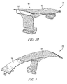
Fig. 3A is a perspective view of the fan annulus filler ofFig. 2 cut away across line 3-3 showing that the body includes a polymer core and the coating is a nanocrystalline structural plating; -
Fig. 3B is a perspective view of another fan annulus filler similar to the the fan annulus filler ofFig. 2 cut away to show that the body is hollow after a core has been leeched out to leave a shell of coating, and showing the coating is a nanocrystalline structural plating; -
Fig. 4 is a perspective view of the fan annulus filler ofFig. 2 having a portion of the coating cut away to show the core of the the body; -
Fig. 5 is an illustrative flow process of making the fan annulus filler ofFig. 2 showing the steps of forming a body from a core, and coating an exterior surface of the body with a nanocrystalline coating; -
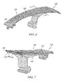
Fig. 6 is a perspective view of another illustrative embodiment of a fan annulus filler adapted for use in an engine like the engine shown inFig. 1 showing that the coating forms a shell which is reinforced by (phantom) reinforcing pins arranged within the shell; -
Fig. 7 is a perspective view of the fan annulus filler ofFig. 6 cut away along the line 7-7 showing that the reinforcement pins are disposed within the shell and that the core has been leached out from the body to leave empty space around the reinforcement pins; -
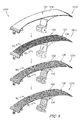
Fig. 8 is an illustrative flow process of making the fan annulus filler ofFig. 6 showing the stages of forming a body with a core, forming bores through the body, coating an exterior surface of the body with a nanocrystalline coating and filling the bores with the nanocrystalline coating to form reinforcement pins within the body, and leaching out the core to leave a shell having reinforcement pins arranged within; -
Fig. 9A is a perspective view of a cross-section of the fan annulus filler from the flow process ofFig. 8 cut away along theline 9A-9A to show that, after the stage of forming bores through the body, the bores penetrate through the core of the body; -
Fig. 9B is a perspective view of a cross-section of the fan annulus filler from the flow process ofFig. 8 cut away along theline 9B-9B to show that, after the stage of coating an exterior surface of the body with a nanocrystalline coating and filling the bores with the nanocrystalline coating to form reinforcement pins, the reinforcement pins are formed within the body and the core remains within the body; -
Fig. 9C is a perspective view of a cross-section of the fan annulus filler from the flow process ofFig. 8 cut away along theline 9C-9C to show that, after the stage of leaching out the core to leave a shell having reinforcement pins arranged within, the reinforcement pins are within the body and the core has been leached out from the body to leave the shell. - These and other features of the present disclosure will become more apparent from the following description of the illustrative embodiments.
- For the purposes of promoting an understanding of the principles of the disclosure, reference will now be made to a number of illustrative embodiments illustrated in the drawings and specific language will be used to describe the same.
- An illustrative
gas turbine engine 10 is cut-away to show that theengine 10 includes afan assembly 12 and anengine core 14 adapted to drive thefan assembly 12 as shown inFig. 1 . Thefan assembly 12 is adapted to push air to provide propulsion for use, for example by an aircraft. Theengine core 14 includes acompressor 16, acombustor 18, and aturbine 20 as shown inFig. 1 . Thecompressor 16 compresses and delivers air to thecombustor 18. Thecombustor 18 mixes fuel with the compressed air received from thecompressor 16 and ignites the fuel. The hot, high-pressure exhaust products of the combustion reaction in thecombustor 18 are directed into theturbine 20 and theturbine 20 extracts work to drive thecompressor 16 and thefan assembly 12. - The
fan assembly 12 includes a plurality offan blades 24 attached at their radially inward ends to afan rotor 15 as suggested inFig. 1 . Thefan blades 24 are illustratively distributed evenly around a circumference of thefan rotor 15. Eachfan blade 24 is illustratively separated from the adjacent fan blade by a fan gap 26. Afan annulus filler 28 is illustratively disposed within each fan gap 26 to assist in directing incoming air towards thefan blades 24. - The
fan annulus filler 28 includes acoating 30 illustratively shown inFig. 2 . Thecoating 30 is illustratively disposed on an all exterior portions of theannulus filler 28. Theannulus filler 28 includes aflow surface 32 formed by thecoating 30 on a top side thereof. Theannulus filler 28 includessides 29 each configured to receive a seal. The annulus fill includes ahook 34 illustratively extending from a bottom side for connection to thefan rotor 15 of thefan assembly 12. - As illustratively suggested in the cross-section of
Fig. 3A , theannulus filler 28 includes abody 36. Thebody 36 is illustratively formed of a core material and includes anexterior surface 38 onto which thecoating 30 is disposed as shown inFig. 4 . As suggested inFig. 3A , thebody 36 is illustratively formed of an injection moldedpolymer core 37. In some embodiments, thebody 36 may comprise one or more of polyether ether ketone (PEEK), acrylonitrile butadiene styrene (ABS), polyethylenimine (PEI), and nylon GF. In some embodiments, thebody 36 may be formed of a core which has a melting temperature of less than 200 °F, and in some embodiments, from about 150 to 200 °F. - The
coating 30 is illustratively formed of a nanocrystalline coating to form nanocrystalline structural plating. Nanocrystalline is defined as a polycrystalline having a grain size generally of 100 nm or less, but functional equivalents above the 100 nm threshold may suffice depending on their specific characteristics. - In the illustrative embodiment, the
coating 30 is disposed with uniform thickness in the range of about 0.001 to 0.150 inches at all points on the exterior of thebody 36. In some embodiments, thecoating 30 may be disposed with a uniform thickness of about 0.001 to 0.125 at all points on the exterior of the body. In some embodiments, thecoating 30 may have different thicknesses each from about 0.001 to 0.150 at different points on the exterior of thebody 36 according to performance requirements. For example thecoating 30 may be thicker along theflow surface 32 and/or along the hook 34 (i.e., the interface with the fan rotor 15) than along the other portions of theannulus filler 28. Thicker coating along theflow surface 32 and/orhook 34 may increase resistance to impacts during operation of theengine 10. In some embodiments, the coating may include NANOVATE®, for example one or more of N1210, N1010, N2020, and or N2025. In some embodiments, thecoating 30 may be disposed on thebody 36 such that final dimensions are reached without additional finish machining to form theflow surface 34. In some embodiments, a rubberized coating may be applied onto thecoating 30 to form a finished surface as theflow surface 34. - In some illustrative embodiments, as shown in
Fig. 3B , the core of thebody 36 of theannulus filler 28 may be leached from within thecoating 30 to leave ashell 40. Theshell 40 is illustratively formed of thecoating 30 arranged to define a hollow space inside thebody 36 where the core had previously occupied as suggested inFig. 3B . - As suggested in the
illustrative flow process 1100 ofFig. 5 , theannulus filler 28 is formed instages body 1110 and coating thebody 1112. In the illustrative embodiment, thestage 1110 of forming thebody 36 comprises injection molding from a core material and thecoating 30 is depicted in phantom for reference (but has not yet been applied). In some embodiments, thestage 1110 of forming thebody 36 may include any suitable manufacturing steps, such as extrusion. Thestage 1112 of coating the body is illustratively embodied as electroplating with a nanocrystalline and a portion of thecoating 30 has been cut away to show thebody 36. In some embodiments, thecoating stage 1112 may include any suitable manner of depositing thecoating 30 on thebody 36 for use in theannulus filler 28, such as spraying. - In another illustrative embodiment, a
fan annulus filler 128 is shown inFig. 6 . In the figures, and as used herein, generally like-features of different embodiments are denoted by like-reference numerals, and the description that follows generally describes additions and/or differences in the various features unless otherwise indicated. - The
annulus filler 128 illustratively includes abody 136 and reinforcement pins 142 disposed within thebody 136. Acoating 130 is illustratively disposed around thebody 136. The reinforcement pins 142 each illustratively connect to oneinner side 144 of thecoating 130 and extend radially through thebody 136 to connect with anotherinner side 146 of thecoating 130 as suggested inFig. 7 . The reinforcement pins 142 are illustratively formed of thecoating 130. The reinforcement pins 142 are illustratively distributed in a relatively even manner along the entire length of theannulus filler 128. In some embodiments, the reinforcement pins 142 may be have non-uniform distribution and may only be distributed in certain portions of the length of theannulus filler 128. In some embodiments, the reinforcement pins 142 may have any orientation relative to the rotatingaxis 21 of theengine 10. - The
body 130 comprises a hollow cavity shown inFig. 7 after having a core material leached from within thecoating 130. Thecoating 130 which remains after leaching out the core from thebody 136 forms ashell 140. The reinforcement pins 142 remain within thebody 136 to provide structural strength for theshell 140. The dimensions and shaped of theannulus filler 128 are illustratively embodied to be the generally the same as other annulus fillers not comprised of a body and coating. However, the reinforcement pins 142 within theshell 140 may permit elimination or reduction of certain dimensions or features, such as eliminatingfillets 141 as suggested inFig. 7 , that may be desired for some other annulus fillers, such as machined aluminum annulus fillers. - As suggested in the
illustrative flow process 1200 ofFig. 8 , theannulus filler 128 is formed in stages depicted from top to bottom, includingstage 1210 forming thebody 136 with a core,stage 1212 formingbores 148 in thebody 136,stage 1214 coating thebody 136 with thecoating 130 and filling thebores 148 with thecoating 130 to form the reinforcement pins 142, andstage 1216 leaching out the core from within thebody 136. In thestage 1210 of forming thebody 136 illustratively includes extruding thebody 136 from a polymer core. - The
stage 1212 of formingbores 148 in thebody 136 includes drilling bores 148 through thebody 136. In some embodiments, bores 148 may be formed by any suitable manner such as being molded in place during the stage of forming thebody 136. A cross-section taken along theline 9A-9A is suggested inFig. 9A showing that thebores 148 penetrate through thebody 136. - In the
stage 1214, coating 130 is applied to anexterior surface 138 of thebody 136 and thecoating 130 fills thebores 148 to form the reinforcement pins 142. A cross-section taken along theline 9B-9B is shown inFig. 9B showing that the reinforcement pins 142 are formed ofcoating 130 filling thebores 148 and extending through the body to connect on one end with aninner side 144 of thecoating 130 and to connect on another end with anotherinner side 146 of thecoating 130. As suggested inFig. 9B , at this point in the flow process, the reinforcement pins 142 have been formed but the core still fills thebody 136 as it has not been leached out. - In
stage 1216, the core of thebody 136 is leached out to leaveshell 140 formed of thecoating 130. In the cross-section taken alongline 9C-9C is suggested inFig. 9C showing that the core has been leached out to leave theshell 140 and such that thebody 138 includes a hollow cavity with the reinforcement pins 142 remaining to provide structural support to theshell 140. - The present disclosure is directed to a light-weight, cost-effective annulus filler that is without forged and machined aluminum. Instead, the annulus filler of the present disclosure may include a polymer and a nanocrystalline coating. In some embodiments, the polymer may be leached out from within the coating to leave a shell.
- In some embodiments, the core of the
body 136 of theannulus filler 128 may not be leached out but may be left inside thecoating 130 with the reinforcement pins 142. In some embodiments, the core of thebody 136 may be leached out to leave the hollow cavity and may be filled back in with another material. In some embodiments, leaching may include heating theannulus filler 128 to a temperature of no more than 400 °F, and in some embodiments no more than 300 °F. - Although the present disclosure has been described with reference to particular means, materials, and embodiments, from the foregoing description, one skilled in the art can easily ascertain the essential characteristics of the present disclosure and various changes and modifications may be made to adapt the various uses and characteristics without departing from the spirit and scope of the present disclosure.
Claims (15)
- A fan annulus filler (28, 128) for mounting on a turbine engine (10), the annulus filler (28, 128) comprising:a filler body (36, 136) including a hook (34) extending therefrom for coupling to a rotor disc, the filler body (36, 136) being made of a polymer; anda nanocrystalline coating (30, 130) disposed on an exterior surface (38, 138) of the filler body (36, 136).
- The fan annulus filler (28, 128) of claim 1, wherein the coating (30, 130) has a thickness of about 0.001 - 0.150 inches at all points along the exterior surface (38, 138) of the body (36, 136).
- The fan annulus filler (28, 128) of one of the preceding claims, wherein the polymer is selected from the group consisting of polyether ether ketone, acrylonitrile butadiene styrene, polyethylenimine, and Nylon GF.
- The fan annulus filler (28, 128) of one of the preceding claims, wherein the nanocrystalline coating (30, 130) is nickel-based alloy coating (30, 130).
- The fan annulus filler (28, 128) of one of the preceding claims, wherein the body (36,136) includes a plurality of bores (148) defined therein and extending through the body (36, 136) between one portion of the exterior surface (38, 138) and another portion of the exterior surface (38, 138).
- The fan annulus filler (28, 128) of claim 5, wherein the coating (30, 130) is disposed within the bores (148) to fill the bores (148) and provide reinforcement pins (142) that extend through the body (36,136).
- A method of making a fan annulus filler (28, 128) for mounting on a turbine engine (10), the method comprising the steps of:forming an annulus filler body (36, 136) with a polymer; andcoating an exterior surface (38, 138) of the filler body (36, 136) with a nanocrystalline coating (30, 130).
- The method of claim 7, wherein forming the filler body (36, 136) is selected from the group consisting of injection molding and extruding.
- The method of claim 7, further comprising, before coating the body (36, 136), forming bores (148) penetrating through the body (36, 136).
- The method of claim 9, wherein the step of coating (30, 130) the body (36, 136) includes filling the bores (148) with the nanocrystalline coating (30,130) to form reinforcement pins (142).
- The method of one of the claims 7 to 10, further comprising, after the step of coating (30, 130) the body (36, 136) removing the polymer from the nanocrystalline coating (30, 130) to leave a shell (40, 140) of the nanocrystalline coating (30, 130).
- The method of claim 11, wherein the step of removing the polymer comprises heating the annulus filler (28, 128) to a temperature of about 150 - 200 °F and/or to a temperature of less than 400 °F.
- The method of one of the claims 7 to 12, wherein a melting point temperature of the polymer is lower than a melting point temperature of the coating (30, 130).
- The method of one of the claims 7 to 13, wherein the step of coating (30, 130) includes applying the nanocrystalline coating (30, 130) to an exterior surface (38, 138) of the body (36, 136) to form a finished surface that requires no machining and forms a flow surface (34) for use in the gas turbine engine (10).
- The method of one of the claims 7 to 14, further comprising coating (30, 130) the nanocrystalline coating (30, 130) with a rubberized coating (30, 130) to form a finished surface that requires no machining and forms a flow surface (34) for use in the gas turbine engine (10).
Applications Claiming Priority (2)
| Application Number | Priority Date | Filing Date | Title |
|---|---|---|---|
| US201462036900P | 2014-08-13 | 2014-08-13 | |
| US14/820,892 US9926798B2 (en) | 2014-08-13 | 2015-08-07 | Method for manufacturing composite fan annulus filler having nano-coating |
Publications (2)
| Publication Number | Publication Date |
|---|---|
| EP2985366A1 true EP2985366A1 (en) | 2016-02-17 |
| EP2985366B1 EP2985366B1 (en) | 2018-01-17 |
Family
ID=54291016
Family Applications (1)
| Application Number | Title | Priority Date | Filing Date |
|---|---|---|---|
| EP15180607.2A Active EP2985366B1 (en) | 2014-08-13 | 2015-08-11 | Composite fan annulus filler with nanocrystalline coating |
Country Status (2)
| Country | Link |
|---|---|
| US (1) | US9926798B2 (en) |
| EP (1) | EP2985366B1 (en) |
Cited By (1)
| Publication number | Priority date | Publication date | Assignee | Title |
|---|---|---|---|---|
| WO2021176161A1 (en) | 2020-03-03 | 2021-09-10 | Safran Aircraft Engines | Composite platform for a fan of an aircraft turbine engine |
Families Citing this family (4)
| Publication number | Priority date | Publication date | Assignee | Title |
|---|---|---|---|---|
| US11143103B2 (en) | 2019-04-10 | 2021-10-12 | Rolls-Royce Corporation | Nose cone and fan assembly |
| US12421860B2 (en) | 2023-04-27 | 2025-09-23 | Rolls-Royce Plc | Annulus filler for a gas turbine engine |
| US12352175B2 (en) | 2023-07-04 | 2025-07-08 | Rolls-Royce Plc | Annulus filler for a gas turbine engine |
| CN120251395A (en) * | 2024-01-04 | 2025-07-04 | 和谐工业有限责任公司 | Air turbine starter |
Citations (4)
| Publication number | Priority date | Publication date | Assignee | Title |
|---|---|---|---|---|
| EP2090749A2 (en) * | 2008-02-18 | 2009-08-19 | Rolls-Royce plc | Annulus filler |
| EP2108786A2 (en) * | 2008-04-07 | 2009-10-14 | Rolls-Royce plc | Aeroengine fan assembly |
| US20120082553A1 (en) * | 2010-09-30 | 2012-04-05 | Andreas Eleftheriou | Metal encapsulated stator vane |
| GB2484988A (en) * | 2010-11-01 | 2012-05-02 | Rolls Royce Plc | Annulus filler for gas turbine engine rotor disc |
Family Cites Families (10)
| Publication number | Priority date | Publication date | Assignee | Title |
|---|---|---|---|---|
| FR2716502B1 (en) | 1994-02-23 | 1996-04-05 | Snecma | Sealing between vanes and intermediate platforms. |
| US6217283B1 (en) | 1999-04-20 | 2001-04-17 | General Electric Company | Composite fan platform |
| FR2858351B1 (en) | 2003-07-31 | 2006-01-13 | Snecma Moteurs | INTER-AUBES SIDE-FLOWING PLATFORM FOR A TURBOREACTOR BLADE SUPPORT |
| US7094021B2 (en) | 2004-02-02 | 2006-08-22 | General Electric Company | Gas turbine flowpath structure |
| FR2914008B1 (en) | 2007-03-21 | 2009-10-09 | Snecma Sa | ROTARY ASSEMBLY OF A TURBOMACHINE BLOWER |
| US7931442B1 (en) | 2007-05-31 | 2011-04-26 | Florida Turbine Technologies, Inc. | Rotor blade assembly with de-coupled composite platform |
| US20120082541A1 (en) | 2010-09-30 | 2012-04-05 | Enzo Macchia | Gas turbine engine casing |
| US8871297B2 (en) | 2010-09-30 | 2014-10-28 | Barry Barnett | Method of applying a nanocrystalline coating to a gas turbine engine component |
| US9429029B2 (en) | 2010-09-30 | 2016-08-30 | Pratt & Whitney Canada Corp. | Gas turbine blade and method of protecting same |
| EP3019727A4 (en) * | 2013-07-09 | 2017-05-10 | United Technologies Corporation | Plated polymer turbine component |
-
2015
- 2015-08-07 US US14/820,892 patent/US9926798B2/en active Active
- 2015-08-11 EP EP15180607.2A patent/EP2985366B1/en active Active
Patent Citations (4)
| Publication number | Priority date | Publication date | Assignee | Title |
|---|---|---|---|---|
| EP2090749A2 (en) * | 2008-02-18 | 2009-08-19 | Rolls-Royce plc | Annulus filler |
| EP2108786A2 (en) * | 2008-04-07 | 2009-10-14 | Rolls-Royce plc | Aeroengine fan assembly |
| US20120082553A1 (en) * | 2010-09-30 | 2012-04-05 | Andreas Eleftheriou | Metal encapsulated stator vane |
| GB2484988A (en) * | 2010-11-01 | 2012-05-02 | Rolls Royce Plc | Annulus filler for gas turbine engine rotor disc |
Cited By (3)
| Publication number | Priority date | Publication date | Assignee | Title |
|---|---|---|---|---|
| WO2021176161A1 (en) | 2020-03-03 | 2021-09-10 | Safran Aircraft Engines | Composite platform for a fan of an aircraft turbine engine |
| FR3107914A1 (en) * | 2020-03-03 | 2021-09-10 | Safran Aircraft Engines | COMPOSITE PLATFORM FOR AN AIRCRAFT TURBOMACHINE BLOWER |
| US11891913B2 (en) | 2020-03-03 | 2024-02-06 | Safran Aircraft Engines | Composite platform for a fan of an aircraft turbine engine |
Also Published As
| Publication number | Publication date |
|---|---|
| US20160047261A1 (en) | 2016-02-18 |
| EP2985366B1 (en) | 2018-01-17 |
| US9926798B2 (en) | 2018-03-27 |
Similar Documents
| Publication | Publication Date | Title |
|---|---|---|
| EP2990506B1 (en) | Composite fan slider with nano-coating | |
| US9926798B2 (en) | Method for manufacturing composite fan annulus filler having nano-coating | |
| EP3677749B1 (en) | Composite platform with lattice structure | |
| EP2353830A2 (en) | Method of manufacturing a composite fan blade with co-cured sheath, and corresponding fan blade | |
| CN104160114B (en) | Composite rotor and vane assembly with integral airfoils | |
| EP3263910B1 (en) | Composite blade for a modular axial flow fan and method of manufacturing the same | |
| CN1932248B (en) | Hybrid turbine | |
| EP3736412B1 (en) | Fan inter-blade platform with core and polymer matrix composite skin | |
| EP2511480A2 (en) | Annulus filler system | |
| US6233823B1 (en) | Method of making plastically formed hybrid airfoil | |
| US9217333B2 (en) | Composite-material vane | |
| EP2971522B1 (en) | Airfoil with leading edge reinforcement | |
| US9878501B2 (en) | Method of manufacturing a frangible blade | |
| CN118517313A (en) | Turbine engine with composite airfoil | |
| US9243512B1 (en) | Rotary machine with a frangible composite blade | |
| JP2001073997A (en) | Injection molded hybrid airfoil | |
| US3905722A (en) | Fluid flow machines | |
| EP3000978B1 (en) | Variable vane ring band with nano-coating | |
| EP3683402B1 (en) | Airfoil with body and cover panel | |
| EP3578807B1 (en) | Method of manufacturing wind turbine rotor blades | |
| EP3633148B1 (en) | Composite cast porous metal turbine component and corresponding fabricating methods | |
| CN110318828A (en) | Conduit assembly and forming method | |
| RU2769595C1 (en) | Method for manufacturing an aircraft engine impeller from a composite material | |
| EP3009212B1 (en) | Manufacturing method of a leading edge of an aerofoil component | |
| CN117989167A (en) | Airfoil and assembly method thereof |
Legal Events
| Date | Code | Title | Description |
|---|---|---|---|
| PUAI | Public reference made under article 153(3) epc to a published international application that has entered the european phase |
Free format text: ORIGINAL CODE: 0009012 |
|
| AK | Designated contracting states |
Kind code of ref document: A1 Designated state(s): AL AT BE BG CH CY CZ DE DK EE ES FI FR GB GR HR HU IE IS IT LI LT LU LV MC MK MT NL NO PL PT RO RS SE SI SK SM TR |
|
| AX | Request for extension of the european patent |
Extension state: BA ME |
|
| 17P | Request for examination filed |
Effective date: 20160816 |
|
| RBV | Designated contracting states (corrected) |
Designated state(s): AL AT BE BG CH CY CZ DE DK EE ES FI FR GB GR HR HU IE IS IT LI LT LU LV MC MK MT NL NO PL PT RO RS SE SI SK SM TR |
|
| 17Q | First examination report despatched |
Effective date: 20161222 |
|
| GRAP | Despatch of communication of intention to grant a patent |
Free format text: ORIGINAL CODE: EPIDOSNIGR1 |
|
| INTG | Intention to grant announced |
Effective date: 20171005 |
|
| GRAS | Grant fee paid |
Free format text: ORIGINAL CODE: EPIDOSNIGR3 |
|
| GRAA | (expected) grant |
Free format text: ORIGINAL CODE: 0009210 |
|
| AK | Designated contracting states |
Kind code of ref document: B1 Designated state(s): AL AT BE BG CH CY CZ DE DK EE ES FI FR GB GR HR HU IE IS IT LI LT LU LV MC MK MT NL NO PL PT RO RS SE SI SK SM TR |
|
| REG | Reference to a national code |
Ref country code: GB Ref legal event code: FG4D |
|
| REG | Reference to a national code |
Ref country code: CH Ref legal event code: EP |
|
| REG | Reference to a national code |
Ref country code: IE Ref legal event code: FG4D |
|
| REG | Reference to a national code |
Ref country code: AT Ref legal event code: REF Ref document number: 964489 Country of ref document: AT Kind code of ref document: T Effective date: 20180215 |
|
| REG | Reference to a national code |
Ref country code: DE Ref legal event code: R096 Ref document number: 602015007547 Country of ref document: DE |
|
| REG | Reference to a national code |
Ref country code: NL Ref legal event code: MP Effective date: 20180117 |
|
| REG | Reference to a national code |
Ref country code: LT Ref legal event code: MG4D |
|
| REG | Reference to a national code |
Ref country code: AT Ref legal event code: MK05 Ref document number: 964489 Country of ref document: AT Kind code of ref document: T Effective date: 20180117 |
|
| PG25 | Lapsed in a contracting state [announced via postgrant information from national office to epo] |
Ref country code: NL Free format text: LAPSE BECAUSE OF FAILURE TO SUBMIT A TRANSLATION OF THE DESCRIPTION OR TO PAY THE FEE WITHIN THE PRESCRIBED TIME-LIMIT Effective date: 20180117 |
|
| PG25 | Lapsed in a contracting state [announced via postgrant information from national office to epo] |
Ref country code: NO Free format text: LAPSE BECAUSE OF FAILURE TO SUBMIT A TRANSLATION OF THE DESCRIPTION OR TO PAY THE FEE WITHIN THE PRESCRIBED TIME-LIMIT Effective date: 20180417 Ref country code: CY Free format text: LAPSE BECAUSE OF FAILURE TO SUBMIT A TRANSLATION OF THE DESCRIPTION OR TO PAY THE FEE WITHIN THE PRESCRIBED TIME-LIMIT Effective date: 20180117 Ref country code: LT Free format text: LAPSE BECAUSE OF FAILURE TO SUBMIT A TRANSLATION OF THE DESCRIPTION OR TO PAY THE FEE WITHIN THE PRESCRIBED TIME-LIMIT Effective date: 20180117 Ref country code: FI Free format text: LAPSE BECAUSE OF FAILURE TO SUBMIT A TRANSLATION OF THE DESCRIPTION OR TO PAY THE FEE WITHIN THE PRESCRIBED TIME-LIMIT Effective date: 20180117 Ref country code: HR Free format text: LAPSE BECAUSE OF FAILURE TO SUBMIT A TRANSLATION OF THE DESCRIPTION OR TO PAY THE FEE WITHIN THE PRESCRIBED TIME-LIMIT Effective date: 20180117 Ref country code: ES Free format text: LAPSE BECAUSE OF FAILURE TO SUBMIT A TRANSLATION OF THE DESCRIPTION OR TO PAY THE FEE WITHIN THE PRESCRIBED TIME-LIMIT Effective date: 20180117 |
|
| REG | Reference to a national code |
Ref country code: FR Ref legal event code: PLFP Year of fee payment: 4 |
|
| PG25 | Lapsed in a contracting state [announced via postgrant information from national office to epo] |
Ref country code: RS Free format text: LAPSE BECAUSE OF FAILURE TO SUBMIT A TRANSLATION OF THE DESCRIPTION OR TO PAY THE FEE WITHIN THE PRESCRIBED TIME-LIMIT Effective date: 20180117 Ref country code: SE Free format text: LAPSE BECAUSE OF FAILURE TO SUBMIT A TRANSLATION OF THE DESCRIPTION OR TO PAY THE FEE WITHIN THE PRESCRIBED TIME-LIMIT Effective date: 20180117 Ref country code: LV Free format text: LAPSE BECAUSE OF FAILURE TO SUBMIT A TRANSLATION OF THE DESCRIPTION OR TO PAY THE FEE WITHIN THE PRESCRIBED TIME-LIMIT Effective date: 20180117 Ref country code: GR Free format text: LAPSE BECAUSE OF FAILURE TO SUBMIT A TRANSLATION OF THE DESCRIPTION OR TO PAY THE FEE WITHIN THE PRESCRIBED TIME-LIMIT Effective date: 20180418 Ref country code: PL Free format text: LAPSE BECAUSE OF FAILURE TO SUBMIT A TRANSLATION OF THE DESCRIPTION OR TO PAY THE FEE WITHIN THE PRESCRIBED TIME-LIMIT Effective date: 20180117 Ref country code: IS Free format text: LAPSE BECAUSE OF FAILURE TO SUBMIT A TRANSLATION OF THE DESCRIPTION OR TO PAY THE FEE WITHIN THE PRESCRIBED TIME-LIMIT Effective date: 20180517 Ref country code: BG Free format text: LAPSE BECAUSE OF FAILURE TO SUBMIT A TRANSLATION OF THE DESCRIPTION OR TO PAY THE FEE WITHIN THE PRESCRIBED TIME-LIMIT Effective date: 20180417 Ref country code: AT Free format text: LAPSE BECAUSE OF FAILURE TO SUBMIT A TRANSLATION OF THE DESCRIPTION OR TO PAY THE FEE WITHIN THE PRESCRIBED TIME-LIMIT Effective date: 20180117 |
|
| REG | Reference to a national code |
Ref country code: DE Ref legal event code: R097 Ref document number: 602015007547 Country of ref document: DE |
|
| PG25 | Lapsed in a contracting state [announced via postgrant information from national office to epo] |
Ref country code: AL Free format text: LAPSE BECAUSE OF FAILURE TO SUBMIT A TRANSLATION OF THE DESCRIPTION OR TO PAY THE FEE WITHIN THE PRESCRIBED TIME-LIMIT Effective date: 20180117 Ref country code: IT Free format text: LAPSE BECAUSE OF FAILURE TO SUBMIT A TRANSLATION OF THE DESCRIPTION OR TO PAY THE FEE WITHIN THE PRESCRIBED TIME-LIMIT Effective date: 20180117 Ref country code: EE Free format text: LAPSE BECAUSE OF FAILURE TO SUBMIT A TRANSLATION OF THE DESCRIPTION OR TO PAY THE FEE WITHIN THE PRESCRIBED TIME-LIMIT Effective date: 20180117 Ref country code: RO Free format text: LAPSE BECAUSE OF FAILURE TO SUBMIT A TRANSLATION OF THE DESCRIPTION OR TO PAY THE FEE WITHIN THE PRESCRIBED TIME-LIMIT Effective date: 20180117 |
|
| PLBE | No opposition filed within time limit |
Free format text: ORIGINAL CODE: 0009261 |
|
| STAA | Information on the status of an ep patent application or granted ep patent |
Free format text: STATUS: NO OPPOSITION FILED WITHIN TIME LIMIT |
|
| PG25 | Lapsed in a contracting state [announced via postgrant information from national office to epo] |
Ref country code: SK Free format text: LAPSE BECAUSE OF FAILURE TO SUBMIT A TRANSLATION OF THE DESCRIPTION OR TO PAY THE FEE WITHIN THE PRESCRIBED TIME-LIMIT Effective date: 20180117 Ref country code: CZ Free format text: LAPSE BECAUSE OF FAILURE TO SUBMIT A TRANSLATION OF THE DESCRIPTION OR TO PAY THE FEE WITHIN THE PRESCRIBED TIME-LIMIT Effective date: 20180117 Ref country code: DK Free format text: LAPSE BECAUSE OF FAILURE TO SUBMIT A TRANSLATION OF THE DESCRIPTION OR TO PAY THE FEE WITHIN THE PRESCRIBED TIME-LIMIT Effective date: 20180117 Ref country code: SM Free format text: LAPSE BECAUSE OF FAILURE TO SUBMIT A TRANSLATION OF THE DESCRIPTION OR TO PAY THE FEE WITHIN THE PRESCRIBED TIME-LIMIT Effective date: 20180117 |
|
| 26N | No opposition filed |
Effective date: 20181018 |
|
| PG25 | Lapsed in a contracting state [announced via postgrant information from national office to epo] |
Ref country code: SI Free format text: LAPSE BECAUSE OF FAILURE TO SUBMIT A TRANSLATION OF THE DESCRIPTION OR TO PAY THE FEE WITHIN THE PRESCRIBED TIME-LIMIT Effective date: 20180117 |
|
| REG | Reference to a national code |
Ref country code: DE Ref legal event code: R119 Ref document number: 602015007547 Country of ref document: DE |
|
| PG25 | Lapsed in a contracting state [announced via postgrant information from national office to epo] |
Ref country code: MC Free format text: LAPSE BECAUSE OF FAILURE TO SUBMIT A TRANSLATION OF THE DESCRIPTION OR TO PAY THE FEE WITHIN THE PRESCRIBED TIME-LIMIT Effective date: 20180117 |
|
| REG | Reference to a national code |
Ref country code: CH Ref legal event code: PL |
|
| PG25 | Lapsed in a contracting state [announced via postgrant information from national office to epo] |
Ref country code: CH Free format text: LAPSE BECAUSE OF NON-PAYMENT OF DUE FEES Effective date: 20180831 Ref country code: LI Free format text: LAPSE BECAUSE OF NON-PAYMENT OF DUE FEES Effective date: 20180831 Ref country code: LU Free format text: LAPSE BECAUSE OF NON-PAYMENT OF DUE FEES Effective date: 20180811 |
|
| REG | Reference to a national code |
Ref country code: BE Ref legal event code: MM Effective date: 20180831 |
|
| REG | Reference to a national code |
Ref country code: IE Ref legal event code: MM4A |
|
| PG25 | Lapsed in a contracting state [announced via postgrant information from national office to epo] |
Ref country code: IE Free format text: LAPSE BECAUSE OF NON-PAYMENT OF DUE FEES Effective date: 20180811 Ref country code: DE Free format text: LAPSE BECAUSE OF NON-PAYMENT OF DUE FEES Effective date: 20190301 |
|
| PG25 | Lapsed in a contracting state [announced via postgrant information from national office to epo] |
Ref country code: BE Free format text: LAPSE BECAUSE OF NON-PAYMENT OF DUE FEES Effective date: 20180831 |
|
| PG25 | Lapsed in a contracting state [announced via postgrant information from national office to epo] |
Ref country code: MT Free format text: LAPSE BECAUSE OF NON-PAYMENT OF DUE FEES Effective date: 20180811 |
|
| PG25 | Lapsed in a contracting state [announced via postgrant information from national office to epo] |
Ref country code: TR Free format text: LAPSE BECAUSE OF FAILURE TO SUBMIT A TRANSLATION OF THE DESCRIPTION OR TO PAY THE FEE WITHIN THE PRESCRIBED TIME-LIMIT Effective date: 20180117 |
|
| GBPC | Gb: european patent ceased through non-payment of renewal fee |
Effective date: 20190811 |
|
| PG25 | Lapsed in a contracting state [announced via postgrant information from national office to epo] |
Ref country code: PT Free format text: LAPSE BECAUSE OF FAILURE TO SUBMIT A TRANSLATION OF THE DESCRIPTION OR TO PAY THE FEE WITHIN THE PRESCRIBED TIME-LIMIT Effective date: 20180117 |
|
| PG25 | Lapsed in a contracting state [announced via postgrant information from national office to epo] |
Ref country code: MK Free format text: LAPSE BECAUSE OF NON-PAYMENT OF DUE FEES Effective date: 20180117 Ref country code: HU Free format text: LAPSE BECAUSE OF FAILURE TO SUBMIT A TRANSLATION OF THE DESCRIPTION OR TO PAY THE FEE WITHIN THE PRESCRIBED TIME-LIMIT; INVALID AB INITIO Effective date: 20150811 |
|
| PG25 | Lapsed in a contracting state [announced via postgrant information from national office to epo] |
Ref country code: GB Free format text: LAPSE BECAUSE OF NON-PAYMENT OF DUE FEES Effective date: 20190811 |
|
| P01 | Opt-out of the competence of the unified patent court (upc) registered |
Effective date: 20230528 |
|
| PGFP | Annual fee paid to national office [announced via postgrant information from national office to epo] |
Ref country code: FR Payment date: 20250825 Year of fee payment: 11 |