EP2985208B1 - Structure for front part of vehicle - Google Patents
Structure for front part of vehicle Download PDFInfo
- Publication number
- EP2985208B1 EP2985208B1 EP14782649.9A EP14782649A EP2985208B1 EP 2985208 B1 EP2985208 B1 EP 2985208B1 EP 14782649 A EP14782649 A EP 14782649A EP 2985208 B1 EP2985208 B1 EP 2985208B1
- Authority
- EP
- European Patent Office
- Prior art keywords
- vehicle body
- portions
- vehicle
- inclination
- suspension member
- Prior art date
- Legal status (The legal status is an assumption and is not a legal conclusion. Google has not performed a legal analysis and makes no representation as to the accuracy of the status listed.)
- Not-in-force
Links
Images


Classifications
-
- B—PERFORMING OPERATIONS; TRANSPORTING
- B62—LAND VEHICLES FOR TRAVELLING OTHERWISE THAN ON RAILS
- B62D—MOTOR VEHICLES; TRAILERS
- B62D21/00—Understructures, i.e. chassis frame on which a vehicle body may be mounted
- B62D21/15—Understructures, i.e. chassis frame on which a vehicle body may be mounted having impact absorbing means, e.g. a frame designed to permanently or temporarily change shape or dimension upon impact with another body
- B62D21/152—Front or rear frames
-
- B—PERFORMING OPERATIONS; TRANSPORTING
- B62—LAND VEHICLES FOR TRAVELLING OTHERWISE THAN ON RAILS
- B62D—MOTOR VEHICLES; TRAILERS
- B62D21/00—Understructures, i.e. chassis frame on which a vehicle body may be mounted
- B62D21/11—Understructures, i.e. chassis frame on which a vehicle body may be mounted with resilient means for suspension, e.g. of wheels or engine; sub-frames for mounting engine or suspensions
-
- B—PERFORMING OPERATIONS; TRANSPORTING
- B62—LAND VEHICLES FOR TRAVELLING OTHERWISE THAN ON RAILS
- B62D—MOTOR VEHICLES; TRAILERS
- B62D21/00—Understructures, i.e. chassis frame on which a vehicle body may be mounted
- B62D21/15—Understructures, i.e. chassis frame on which a vehicle body may be mounted having impact absorbing means, e.g. a frame designed to permanently or temporarily change shape or dimension upon impact with another body
- B62D21/152—Front or rear frames
- B62D21/155—Sub-frames or underguards
-
- B—PERFORMING OPERATIONS; TRANSPORTING
- B62—LAND VEHICLES FOR TRAVELLING OTHERWISE THAN ON RAILS
- B62D—MOTOR VEHICLES; TRAILERS
- B62D25/00—Superstructure or monocoque structure sub-units; Parts or details thereof not otherwise provided for
- B62D25/08—Front or rear portions
- B62D25/082—Engine compartments
Definitions
- the present invention relates to a vehicle front portion structure.
- Document US 2011/0198889 A1 discloses a vehicle front portion structure comprising front side members that are disposed along a vehicle body longitudinal direction, and that have inclined portions that cause vehicle body front portion sides to be positioned higher than vehicle body rear portion sides; and a suspension member that is disposed at a vehicle body front side of the inclined portions, wherein concave portions, that have inclined surfaces that are directed toward a vehicle body front upper side.
- the above-described structure is not a structure in which the sub-frame is made to separate from the front side frame merely due to the stay deforming. Therefore, there is the concern that the sub-frame (the suspension member) will be nipped between the power unit and the front side frame (the front side member). Namely, there is room for improvement in order to efficiently absorb the collision load that is inputted to the sub-frame from the vehicle body front side.
- an object of the present invention is to obtain a vehicle front portion structure that can efficiently absorb collision impact that is inputted from a vehicle front side to a suspension member.
- a vehicle front portion structure of a first aspect relating to the present invention comprises: front side members that are disposed along a vehicle body longitudinal direction, and that have inclined portions that cause vehicle body front portion sides to be positioned higher than vehicle body rear portion sides; and a suspension member that is disposed at a vehicle body front side of the inclined portions, and that has inclined walls whose angle of inclination is made to be smaller than an angle of inclination of the inclined portions, the inclined walls being formed at regions that face the inclined portions, in a side view seen from a vehicle transverse direction.
- the angle of inclination of the inclined walls that are formed at the suspension member is made to be smaller than the angle of inclination of the inclined portions at the front side members. Accordingly, when collision load is inputted from the vehicle body front side and the suspension member moves rearward, it is easy for the inclined walls to move toward the vehicle body rear lower side while being guided by the inclined portions. Namely, the suspension member is moved so as to enter in toward the vehicle body lower sides of the front side members, while interference with the front side members is suppressed. Accordingly, the collision load that is inputted from the vehicle body front side to the suspension member is absorbed efficiently.
- concave portions that have inclined surfaces that are directed toward a vehicle body front upper side, are formed at lower surface sides of the inclined portions, and an angle of inclination of the inclined surfaces is made to be larger than the angle of inclination of the inclined walls, in a side view seen from the vehicle transverse direction.
- the angle of inclination of the inclined surfaces, that are directed toward the vehicle body front upper side, of the concave portions that are formed at the lower surface sides of the inclined portions is made to be greater than the angle of inclination of the inclined walls, in a side view seen from the vehicle transverse direction. Accordingly, when collision load is inputted from the vehicle body front side and the suspension member moves rearward, the inclined walls are moved toward the vehicle body rear lower side while being guided by the inclined surfaces. Namely, the suspension member is moved so as to enter in toward the vehicle body lower sides of the front side members, while interference with front side members is additionally suppressed. Accordingly, the collision load that is inputted from the vehicle body front side to the suspension member is absorbed more efficiently.
- a vehicle front portion structure of a second aspect relating to the present invention comprises: front side members that are disposed along a vehicle body longitudinal direction, and that have inclined portions that cause vehicle body front portion sides to be positioned higher than vehicle body rear portion sides, concave portions, that have inclined surfaces that are directed toward a vehicle body front upper side, being formed at lower surface sides of the inclined portions; and a suspension member that is disposed at a vehicle body front side of the inclined portions, and that has inclined walls whose angle of inclination is made to be smaller than an angle of inclination of the inclined surfaces at the concave portions, the inclined walls being formed at regions that face the inclined surfaces, in a side view seen from a vehicle transverse direction.
- the angle of inclination of the inclined walls that are formed at the suspension members is made to be smaller than the angle of inclination of the inclined surfaces of the concave portions that are formed at the front side members. Accordingly, when collision load is inputted from the vehicle body front side and the suspension member moves rearward, it is easy for the inclined walls to move toward the vehicle body rear lower side while being guided by the inclined surfaces. Namely, the suspension member is moved so as to enter in toward the vehicle body lower sides of the front side members, while interference with front side members is suppressed. Accordingly, the collision load that is inputted from the vehicle body front side to the suspension member is absorbed efficiently.
- a vehicle front portion structure of a third aspect relating to the present invention is the vehicle front portion structure of the first aspect or the second aspect, wherein the suspension member has fastening portions that extend integrally from rear end portions of the inclined walls toward a vehicle body rear side, and that are fastened to lower end portions of the inclined portions.
- the fastening portions that are fastened to the lower end portions of the inclined portions, extend integrally toward the vehicle body rear side from rear end portions of the inclined walls of the suspension members. Accordingly, as compared with a structure in which fastening portions are provided separately from the suspension members, assembling of the suspension members is easy, and a reduction in the manufacturing costs is devised.
- a vehicle front portion structure of a fourth aspect relating to the present invention is the vehicle front portion structure of the third aspect, wherein the fastening portions are formed in flat plate shapes that is configured to bendingly deform toward a vehicle body lower side when collision load is inputted from a vehicle body front side.
- flat plate shaped in the present invention also includes, for example, substantial flat plate shapes whose peripheral edge portions are molded so as to bend toward the vehicle body lower side.
- a vehicle front portion structure of a fifth aspect relating to the present invention is the vehicle front portion structure of the third aspect or the fourth aspect, wherein cap nuts are fixed to the lower end portions of the inclined portions, and the fastening portions are fastened to the lower end portions due to bolts, that are inserted-through through-holes formed at the fastening portions, being screwed-together with the cap nuts.
- the cap nuts with which bolts that fasten the fastening portions are screwed-together, are fixed to the lower end portions of the inclined portions. Namely, the fastening strength of the fastening portions to the lower end portions of the inclined portions is increased. Accordingly, when collision load is inputted from the vehicle body front side to the suspension members, stress concentrates around the through-holes of the fastening portions, and these peripheries of the through-holes break. Due thereto, the suspension members separate from the lower end portions of the inclined portions, and are moved so as to deeply enter in toward the vehicle body lower sides of the front side members. Therefore, the collision load that is inputted from the vehicle body front side to the suspension member is absorbed more efficiently.
- collision load that is inputted from the vehicle body front side to the suspension members can be absorbed more efficiently.
- collision load that is inputted from the vehicle body front side to the suspension members can be absorbed efficiently.
- the suspension members can be assembled easily and a reduction in the manufacturing costs can be devised, as compared with a structure in which the fastening portions are provided separately from the suspension members.
- collision load that is inputted from the vehicle body front side to the suspension members can be absorbed efficiently.
- collision load that is inputted from the vehicle body front side to the suspension members can be absorbed more efficiently.
- arrow UP that is shown appropriately in the respective drawings is the vehicle body upward direction
- arrow FR is the vehicle body frontward direction
- arrow OUT is the vehicle transverse direction outer side.
- vertical, longitudinal, and left-right directions when vertical, longitudinal, and left-right directions are used, they mean the vertical of the vehicle body vertical direction, the longitudinal of the vehicle body longitudinal direction, and the left and right of the vehicle body left-right direction (the vehicle transverse direction), unless otherwise indicated.
- a vehicle front portion structure 10 relating to a first embodiment is described.
- a pair of left and right front side members 12, that are rectangular closed cross-sectional shapes (hollow angular pillar shapes) that extend along the vehicle body longitudinal direction, are disposed at the front portion side of a vehicle at the vehicle body right side and the vehicle body left side so as to be separated from one another by a predetermined interval (only the vehicle body left side is shown in Fig. 2 ).
- An inclined portion (kick portion) 14 that is for causing the vehicle body front portion side to be positioned higher than the vehicle body rear portion side, is formed at the front side member 12. Further, a suspension member 30, that is made of metal (e.g., made of steel) and is described later, is supported at the vehicle body front lower side of the inclined portion 14, i.e., at the vehicle body lower side of the front side member 12 at the vehicle body front portion side that includes the inclined portion 14, in a state of hanging-down from this front side member 12.
- a suspension member 30 that is made of metal (e.g., made of steel) and is described later, is supported at the vehicle body front lower side of the inclined portion 14, i.e., at the vehicle body lower side of the front side member 12 at the vehicle body front portion side that includes the inclined portion 14, in a state of hanging-down from this front side member 12.
- a front side fastened-to portion 16 and a rear side fastened-to portion 18, that are for respectively fastening and fixing a front side fastening portion 36 and a rear side fastening portion 38 that are described later of the suspension member 30, are provided at a vehicle body front portion of the front side member 12 and at a lower end portion of the inclined portion 14.
- the suspension member 30 is disposed so as to overlap the inclined portion 14 in a side view (the height direction) seen from the vehicle transverse direction and in a plan view (the vehicle transverse direction) (see Fig. 2 , Fig. 3 ).
- an upper reinforcement 28 that extends in the vehicle body longitudinal direction and that is disposed at an upper side position due to the peripheral edge portion being fixed by welding to the side wall 12S of the front side member 12, are provided within the front side member 12 at the rear side fastened-to portion 18. Due thereto, the strength (rigidity) of the rear side fastened-to portion 18 is improved.
- through-holes 12A, 26A, 28A that are circular and are for the inserting-through of a cap portion 22 of a cap nut 20 that is described later, are formed respectively in a lower wall 12D of the front side member 12, the lower reinforcement 26, and the upper reinforcement 28 at the rear side fastened-to portion 18 (the lower end portion of the inclined portion 14).
- the cap nut 20 has the cap portion 22 at whose inner peripheral surface a female screw portion is formed, and a flange portion 24 that is annular and that is formed integrally with the outer peripheral surface of the cap portion 22 at the bolt insertion direction upstream side. Further, the height of the cap portion 22 is made to be higher than the interval in the vertical direction from the lower wall 12D to the upper reinforcement 28.
- the cap nut 20 is placed due to the cap portion 22, that is further toward the bolt insertion direction upstream side than the flange portion 24, being inserted-through the through-hole 12A of the lower wall 12D before the lower reinforcement 26 and the upper reinforcement 28 are provided. Further, at the time of inserting the cap portion 22 through the interior of the through-hole 26A and providing the lower reinforcement 26, the outer peripheral portion of the flange portion 24 is fixed to the lower reinforcement 26 by arc welding.
- the outer peripheral surface of the cap portion 22 is fixed to the upper reinforcement 28 by arc welding. Due thereto, the cap nut 20 is fixed securely to the rear side fastened-to portion 18 (the lower reinforcement 26 and the upper reinforcement 28) of the front side member 12.
- the angle of inclination of the inclined surface 15A (the inclined portion 14) is made to be larger than the angle of inclination of an inclined wall 40, that is described later, of the suspension member 30.
- the angle of inclination of the inclined wall 40 of the suspension member 30 is made to be smaller than the angle of inclination of the inclined surface 15A (the inclined portion 14) of the concave portion 15.
- the suspension member 30 has a suspension member main body 32, a pair of corner portions 34 that project so as to extend toward the vehicle body upper outer sides at the front portion sides of the vehicle transverse direction both sides of the suspension member main body 32, the inclined walls 40 that are formed at the rear portion sides of the vehicle transverse direction both sides of the suspension member main body 32 at angles of inclination heading toward the vehicle body lower rear side (the vehicle body upper front side), and the rear side fastening portions 38 that serve as fastening portions that are formed integrally with the rear end portions of the inclined walls 40 so as to extend toward the vehicle body rear side.
- lower arms 42 that structure an unillustrated suspension are mounted to the suspension member main body 32, further toward the vehicle transverse direction outer sides than the corner portions 34.
- an unillustrated power unit that includes an engine and a transmission, is disposed at the vehicle body front side of the suspension member 30.
- the upper end portions of the corner portions 34 are made to be the front side fastening portions 36 in which are formed through-holes 36A through which connecting members 44 that are tubular are inserted.
- the front side fastening portions 36 are fastened and fixed to the front side fastened-to portions 16 of the front side members 12, via the connecting members 44 and by bolts 50 and nuts 48.
- the rear side fastening portion 38 is formed substantially in the shape of a flat plate that is reinforced due to the peripheral edge portion being molded so as to bend toward the vehicle body lower side.
- the through-hole 38A that is for insertion-through of the bolt 50 (see Fig. 4 ), is formed at the rear end portion side of the rear side fastening portion 38. Due to the bolt 50 being inserted-through the through-hole 38A from the vehicle body lower side and being screwed-together with the cap nut 20 that is fixed to the rear side fastened-to portion 18 of the front side member 12, the rear side fastening portion 38 is securely fastened and fixed to the rear side fastened-to portion 18.
- the inclined wall 40 is formed at the portion of the suspension member main body 32 that is at the vehicle body front side of the rear side fastening portion 38, i.e., a region that is adjacent to and faces the inclined surface 15A (the inclined portion 14) of the concave portion 15 in the vehicle body longitudinal direction when the suspension member 30 is mounted to the front side member 12.
- the angle of inclination of the inclined wall 40 is made to be smaller than the angle of inclination of the inclined surface 15A (the inclined portion 14) of the concave portion 15.
- the formation position of this inclined surface 15A (the concave portion 15) is set such that a virtual straight line K2 that runs along the inclined surface 15A (i.e., whose angle of inclination is greater than a virtual straight line K1) passes through an intersection point P of the virtual straight line K1 that runs along the inclined wall 40 and a virtual horizontal plane L that runs along the rear side fastening portion 38.
- this intersection point P is at the front end portion of the rear side fastening portion 38 (the rear end portion of the inclined wall 40), and, at the time of a full-overlap frontal collision, becomes the starting point of the bending deformation of the rear side fastening portion 38 toward the vehicle body lower side.
- the inclined surface 15A (the concave portion 15) is formed up to a range that goes past, toward the vehicle body front side and the vehicle body rear side respectively, the front end portion and the rear end portion of the inclined wall 40 that overlaps the inclined portion 14 as seen in plan view.
- the power unit moves toward the vehicle body rear side (moves rearward), and some of this collision load is inputted to the suspension member main body 32 of the suspension member 30. Thereupon, the suspension member main body 32 moves toward the vehicle body rear side (moves rearward).
- the angle of inclination of the inclined wall 40 is made to be smaller than the angle of inclination of the inclined portion 14 (the inclined surface 15A of the concave portion 15).
- the suspension member main body 32 moves rearward, the inclined wall 40 contacts the inclined portion 14 (the inclined surface 15A), and moves toward the vehicle body rear lower side while being guided by this inclined portion 14 (inclined surface 15A) (shown by arrow F in Fig. 5 ). Namely, the suspension member main body 32 is displaced toward the intersection point P.
- the rear side fastening portion 38 is formed substantially in the shape of a plate. Accordingly, the rear side fastening portion 38 bendingly deforms toward the vehicle body lower side with the intersection point P being the starting point. Note that, at this time, because the suspension member main body 32 is displaced rectilinearly toward the intersection point P, there is no loss of the input of load toward the intersection point P, and bending deformation can be brought about at the rear side fastening portion 38 at an early stage by input of a low load.
- the suspension member main body 32 (the suspension member 30) is moved so as to deeply enter in toward the vehicle body lower side of the front side member 12, while interference with the inclined portion 14 is suppressed (mitigated). Accordingly, the collision load, that is inputted to the suspension member 30 from the vehicle body front side, can be absorbed (released) efficiently.
- the rear side fastening portion 38 extends integrally toward the vehicle body rear side from the rear end portion of the inclined wall 40 of the suspension member 30. Accordingly, as compared with a structure in which the rear side fastening portion 38 is provided separately from the suspension member 30, assembling of the suspension member 30 is easy, and a reduction in manufacturing costs can be devised. Namely, an increase in the number of parts and an increase in the manufacturing costs at the time of manufacturing the suspension member 30 can be suppressed or prevented.
- the vehicle front portion structure 10 relating to the second embodiment is described next. Note that regions that are equivalent to those of the above-described first embodiment are denoted by the same reference numerals, and detailed description thereof (including the operation) is omitted as appropriate.
- the angle of inclination of the inclined wall 40 of the suspension member 30 is made to be the same as or greater than the angle of inclination of the inclined portion 14.
- the angle of inclination of the inclined wall 40 relating to this second embodiment is made to be smaller than the angle of inclination of the inclined surface 15A of the concave portion 15 that is formed at least at the lower surface side and the vehicle transverse direction inner side of the inclined portion 14 of the front side member 12.
- the inclined surface 15A (the concave portion 15) is formed at the front end portion side of the inclined wall 40 that overlaps the inclined portion 14 in plan view, and up to a range that goes past, toward the vehicle body rear side, a proximate point T in a side view seen from the vehicle transverse direction, so as to cover the proximate point T that the inclined portion 14 is nearest to.
- the second embodiment that has such a structure, operation and effects that are equivalent to those of the above-described first embodiment are obtained.
- the power unit moves toward the vehicle body rear side (moves rearward), and some of this collision load is inputted to the suspension member main body 32 of the suspension member 30. Thereupon, the suspension member main body 32 moves toward the vehicle body rear side (moves rearward).
- the angle of inclination of the inclined wall 40 is made to be smaller than the angle of inclination of the inclined surface 15A of the concave portion 15. Accordingly, as shown in Fig. 8 , when the suspension member main body 32 moves rearward, the front end portion side of the inclined wall 40 (including the proximate point T) contacts the inclined surface 15A, and moves toward the vehicle body rear lower side while being guided by this inclined surface 15A (shown by arrow F in Fig. 8 ).
- the suspension member main body 32 is displaced toward the intersection point P, and due thereto, the rear side fastening portion 38 is bendingly deformed toward the vehicle body lower side with the intersection point P being the starting point. Then, as shown in Fig. 9 , when the bending deformation of the rear side fastening portion 38 progresses, the movement of the suspension member main body 32 toward the vehicle body rear lower side progresses (shown by arrow F in Fig. 9 ), and the rear side fastening portion 38 separates from the rear side fastened-to portion 18.
- the suspension member main body 32 (the suspension member 30) is moved so as to deeply enter in toward the vehicle body lower side of the front side member 12, while interference with the inclined portion 14 is suppressed (mitigated). Accordingly, the collision load, that is inputted to the suspension member 30 from the vehicle body front side, can be absorbed (released) efficiently.
- the vehicle front portion structure 10 relating to the present embodiment has been described above on the basis of the drawings, the vehicle front portion structure 10 relating to the present embodiment is not limited to the illustrated structure, and the design thereof can be changed appropriately within a scope that does not depart from the scope of the present invention.
- the concave portion 15 (the inclined surface 15A) does not have to be formed at the inclined portion 14.
- the structure of increasing the fastening strength of the rear side fastening portion 38 to the rear side fastened-to portion 18 is not limited to the structure that includes the cap nut 20.
Description
- The present invention relates to a vehicle front portion structure.
- There is conventionally known a structure in which the rear end portion of a sub-frame and a front side frame are joined by a stay, and, at the time of a frontal collision of the vehicle, the collision load is absorbed by deforming the stay (see, for example, Japanese Patent Application Laid-Open (
JP-A) No. 2012-206653 - Document
US 2011/0198889 A1 discloses a vehicle front portion structure comprising front side members that are disposed along a vehicle body longitudinal direction, and that have inclined portions that cause vehicle body front portion sides to be positioned higher than vehicle body rear portion sides; and a suspension member that is disposed at a vehicle body front side of the inclined portions, wherein concave portions, that have inclined surfaces that are directed toward a vehicle body front upper side. - However, the above-described structure is not a structure in which the sub-frame is made to separate from the front side frame merely due to the stay deforming. Therefore, there is the concern that the sub-frame (the suspension member) will be nipped between the power unit and the front side frame (the front side member). Namely, there is room for improvement in order to efficiently absorb the collision load that is inputted to the sub-frame from the vehicle body front side.
- Thus, an object of the present invention is to obtain a vehicle front portion structure that can efficiently absorb collision impact that is inputted from a vehicle front side to a suspension member.
- In order to achieve the above-described object, a vehicle front portion structure of a first aspect relating to the present invention comprises: front side members that are disposed along a vehicle body longitudinal direction, and that have inclined portions that cause vehicle body front portion sides to be positioned higher than vehicle body rear portion sides; and a suspension member that is disposed at a vehicle body front side of the inclined portions, and that has inclined walls whose angle of inclination is made to be smaller than an angle of inclination of the inclined portions, the inclined walls being formed at regions that face the inclined portions, in a side view seen from a vehicle transverse direction.
- In accordance with the first aspect, in a side view seen from the vehicle transverse direction, the angle of inclination of the inclined walls that are formed at the suspension member is made to be smaller than the angle of inclination of the inclined portions at the front side members. Accordingly, when collision load is inputted from the vehicle body front side and the suspension member moves rearward, it is easy for the inclined walls to move toward the vehicle body rear lower side while being guided by the inclined portions. Namely, the suspension member is moved so as to enter in toward the vehicle body lower sides of the front side members, while interference with the front side members is suppressed. Accordingly, the collision load that is inputted from the vehicle body front side to the suspension member is absorbed efficiently.
- Further, in a vehicle front portion structure of a first aspect relating to the present invention, concave portions, that have inclined surfaces that are directed toward a vehicle body front upper side, are formed at lower surface sides of the inclined portions, and an angle of inclination of the inclined surfaces is made to be larger than the angle of inclination of the inclined walls, in a side view seen from the vehicle transverse direction.
- In accordance with the first aspect, the angle of inclination of the inclined surfaces, that are directed toward the vehicle body front upper side, of the concave portions that are formed at the lower surface sides of the inclined portions is made to be greater than the angle of inclination of the inclined walls, in a side view seen from the vehicle transverse direction. Accordingly, when collision load is inputted from the vehicle body front side and the suspension member moves rearward, the inclined walls are moved toward the vehicle body rear lower side while being guided by the inclined surfaces. Namely, the suspension member is moved so as to enter in toward the vehicle body lower sides of the front side members, while interference with front side members is additionally suppressed. Accordingly, the collision load that is inputted from the vehicle body front side to the suspension member is absorbed more efficiently.
- Further, a vehicle front portion structure of a second aspect relating to the present invention comprises: front side members that are disposed along a vehicle body longitudinal direction, and that have inclined portions that cause vehicle body front portion sides to be positioned higher than vehicle body rear portion sides, concave portions, that have inclined surfaces that are directed toward a vehicle body front upper side, being formed at lower surface sides of the inclined portions; and a suspension member that is disposed at a vehicle body front side of the inclined portions, and that has inclined walls whose angle of inclination is made to be smaller than an angle of inclination of the inclined surfaces at the concave portions, the inclined walls being formed at regions that face the inclined surfaces, in a side view seen from a vehicle transverse direction.
- In accordance with the second aspect, in a side view seen from the vehicle transverse direction, the angle of inclination of the inclined walls that are formed at the suspension members is made to be smaller than the angle of inclination of the inclined surfaces of the concave portions that are formed at the front side members. Accordingly, when collision load is inputted from the vehicle body front side and the suspension member moves rearward, it is easy for the inclined walls to move toward the vehicle body rear lower side while being guided by the inclined surfaces. Namely, the suspension member is moved so as to enter in toward the vehicle body lower sides of the front side members, while interference with front side members is suppressed. Accordingly, the collision load that is inputted from the vehicle body front side to the suspension member is absorbed efficiently.
- Further, a vehicle front portion structure of a third aspect relating to the present invention is the vehicle front portion structure of the first aspect or the second aspect, wherein the suspension member has fastening portions that extend integrally from rear end portions of the inclined walls toward a vehicle body rear side, and that are fastened to lower end portions of the inclined portions.
- In accordance with the third aspect, the fastening portions, that are fastened to the lower end portions of the inclined portions, extend integrally toward the vehicle body rear side from rear end portions of the inclined walls of the suspension members. Accordingly, as compared with a structure in which fastening portions are provided separately from the suspension members, assembling of the suspension members is easy, and a reduction in the manufacturing costs is devised.
- Further, a vehicle front portion structure of a fourth aspect relating to the present invention is the vehicle front portion structure of the third aspect, wherein the fastening portions are formed in flat plate shapes that is configured to bendingly deform toward a vehicle body lower side when collision load is inputted from a vehicle body front side.
- In accordance with the fourth aspect, when collision load is inputted from the vehicle body front side to the suspension members, the fastening portions that are flat plate shaped bendingly deform toward the vehicle body lower side. Accordingly, the collision load that is inputted from the vehicle body front side to the suspension member is absorbed efficiently. Note that "flat plate shaped" in the present invention also includes, for example, substantial flat plate shapes whose peripheral edge portions are molded so as to bend toward the vehicle body lower side.
- Further, a vehicle front portion structure of a fifth aspect relating to the present invention is the vehicle front portion structure of the third aspect or the fourth aspect, wherein cap nuts are fixed to the lower end portions of the inclined portions, and the fastening portions are fastened to the lower end portions due to bolts, that are inserted-through through-holes formed at the fastening portions, being screwed-together with the cap nuts.
- In accordance with the fifth aspect, the cap nuts, with which bolts that fasten the fastening portions are screwed-together, are fixed to the lower end portions of the inclined portions. Namely, the fastening strength of the fastening portions to the lower end portions of the inclined portions is increased. Accordingly, when collision load is inputted from the vehicle body front side to the suspension members, stress concentrates around the through-holes of the fastening portions, and these peripheries of the through-holes break. Due thereto, the suspension members separate from the lower end portions of the inclined portions, and are moved so as to deeply enter in toward the vehicle body lower sides of the front side members. Therefore, the collision load that is inputted from the vehicle body front side to the suspension member is absorbed more efficiently.
- In accordance with the first aspect relating to the present invention, collision load that is inputted from the vehicle body front side to the suspension members can be absorbed more efficiently.
- In accordance with the second aspect relating to the present invention, collision load that is inputted from the vehicle body front side to the suspension members can be absorbed efficiently.
- In accordance with the third aspect relating to the present invention, the suspension members can be assembled easily and a reduction in the manufacturing costs can be devised, as compared with a structure in which the fastening portions are provided separately from the suspension members.
- In accordance with the fourth aspect relating to the present invention, collision load that is inputted from the vehicle body front side to the suspension members can be absorbed efficiently.
- In accordance with the fifth aspect relating to the present invention, collision load that is inputted from the vehicle body front side to the suspension members can be absorbed more efficiently.
-
-
Fig. 1 is a perspective view of a suspension member that structures a vehicle front portion structure relating to a first embodiment. -
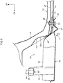
Fig. 2 is a side view showing the vehicle front portion structure relating to the first embodiment. -
Fig. 3 is a partial, enlarged plan view showing main portions of the vehicle front portion structure relating to the first embodiment. -
Fig. 4 is a partial, enlarged side sectional view showing main portions of the vehicle front portion structure relating to the first embodiment. -
Fig. 5 is a side sectional view showing the state immediately after a full-overlap frontal collision, of the vehicle front portion structure relating to the first embodiment. -
Fig. 6 is a side sectional view showing the state after a full-overlap frontal collision, of the vehicle front portion structure relating to the first embodiment. -
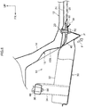
Fig. 7 is a side view showing a vehicle front portion structure relating to a second embodiment. -
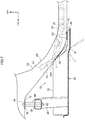
Fig. 8 is a side sectional view showing the state immediately after a full-overlap frontal collision, of the vehicle front portion structure relating to the second embodiment. -
Fig. 9 is a side sectional view showing the state after a full-overlap frontal collision, of the vehicle front portion structure relating to the second embodiment. - Embodiments relating to the present invention are described in detail hereinafter on the basis of the drawings. Note that, for convenience of explanation, arrow UP that is shown appropriately in the respective drawings is the vehicle body upward direction, arrow FR is the vehicle body frontward direction, and arrow OUT is the vehicle transverse direction outer side. Further, in the following description, when vertical, longitudinal, and left-right directions are used, they mean the vertical of the vehicle body vertical direction, the longitudinal of the vehicle body longitudinal direction, and the left and right of the vehicle body left-right direction (the vehicle transverse direction), unless otherwise indicated.
- First, a vehicle
front portion structure 10 relating to a first embodiment is described. As shown inFig. 2 , a pair of left and rightfront side members 12, that are rectangular closed cross-sectional shapes (hollow angular pillar shapes) that extend along the vehicle body longitudinal direction, are disposed at the front portion side of a vehicle at the vehicle body right side and the vehicle body left side so as to be separated from one another by a predetermined interval (only the vehicle body left side is shown inFig. 2 ). - An inclined portion (kick portion) 14, that is for causing the vehicle body front portion side to be positioned higher than the vehicle body rear portion side, is formed at the
front side member 12. Further, asuspension member 30, that is made of metal (e.g., made of steel) and is described later, is supported at the vehicle body front lower side of theinclined portion 14, i.e., at the vehicle body lower side of thefront side member 12 at the vehicle body front portion side that includes theinclined portion 14, in a state of hanging-down from thisfront side member 12. - In detail, a front side fastened-to
portion 16 and a rear side fastened-toportion 18, that are for respectively fastening and fixing a frontside fastening portion 36 and a rearside fastening portion 38 that are described later of thesuspension member 30, are provided at a vehicle body front portion of thefront side member 12 and at a lower end portion of theinclined portion 14. Note that thesuspension member 30 is disposed so as to overlap theinclined portion 14 in a side view (the height direction) seen from the vehicle transverse direction and in a plan view (the vehicle transverse direction) (seeFig. 2 ,Fig. 3 ). - As shown in
Fig. 4 , alower reinforcement 26, that extends in the vehicle body longitudinal direction and that is disposed at a lower side position due to the peripheral edge portion being fixed by welding to aside wall 12S of thefront side member 12, and anupper reinforcement 28, that extends in the vehicle body longitudinal direction and that is disposed at an upper side position due to the peripheral edge portion being fixed by welding to theside wall 12S of thefront side member 12, are provided within thefront side member 12 at the rear side fastened-toportion 18. Due thereto, the strength (rigidity) of the rear side fastened-toportion 18 is improved. - Further, through-
holes cap portion 22 of acap nut 20 that is described later, are formed respectively in alower wall 12D of thefront side member 12, thelower reinforcement 26, and theupper reinforcement 28 at the rear side fastened-to portion 18 (the lower end portion of the inclined portion 14). - The
cap nut 20 has thecap portion 22 at whose inner peripheral surface a female screw portion is formed, and aflange portion 24 that is annular and that is formed integrally with the outer peripheral surface of thecap portion 22 at the bolt insertion direction upstream side. Further, the height of thecap portion 22 is made to be higher than the interval in the vertical direction from thelower wall 12D to theupper reinforcement 28. - Further, the
cap nut 20 is placed due to thecap portion 22, that is further toward the bolt insertion direction upstream side than theflange portion 24, being inserted-through the through-hole 12A of thelower wall 12D before thelower reinforcement 26 and theupper reinforcement 28 are provided. Further, at the time of inserting thecap portion 22 through the interior of the through-hole 26A and providing thelower reinforcement 26, the outer peripheral portion of theflange portion 24 is fixed to thelower reinforcement 26 by arc welding. - Still further, at the time of inserting the
cap portion 22 through the interior of the through-hole 28A and providing theupper reinforcement 28, the outer peripheral surface of thecap portion 22 is fixed to theupper reinforcement 28 by arc welding. Due thereto, thecap nut 20 is fixed securely to the rear side fastened-to portion 18 (thelower reinforcement 26 and the upper reinforcement 28) of thefront side member 12. - Further, as shown in
Fig. 2 andFig. 3 , aconcave portion 15, that has aninclined surface 15A that heads toward the vehicle body front upper side, is formed at the lower surface side and the vehicle transverse direction inner side of theinclined portion 14. In a side view seen from the vehicle transverse direction, the angle of inclination of theinclined surface 15A (the inclined portion 14) is made to be larger than the angle of inclination of aninclined wall 40, that is described later, of thesuspension member 30. In other words, in a side view seen from the vehicle transverse direction, the angle of inclination of theinclined wall 40 of thesuspension member 30 is made to be smaller than the angle of inclination of theinclined surface 15A (the inclined portion 14) of theconcave portion 15. - As shown in
Fig. 1 , thesuspension member 30 has a suspension membermain body 32, a pair ofcorner portions 34 that project so as to extend toward the vehicle body upper outer sides at the front portion sides of the vehicle transverse direction both sides of the suspension membermain body 32, theinclined walls 40 that are formed at the rear portion sides of the vehicle transverse direction both sides of the suspension membermain body 32 at angles of inclination heading toward the vehicle body lower rear side (the vehicle body upper front side), and the rearside fastening portions 38 that serve as fastening portions that are formed integrally with the rear end portions of theinclined walls 40 so as to extend toward the vehicle body rear side. - Note that
lower arms 42 that structure an unillustrated suspension are mounted to the suspension membermain body 32, further toward the vehicle transverse direction outer sides than thecorner portions 34. Further, an unillustrated power unit, that includes an engine and a transmission, is disposed at the vehicle body front side of thesuspension member 30. - As shown in
Fig. 1 andFig. 2 , the upper end portions of thecorner portions 34 are made to be the frontside fastening portions 36 in which are formed through-holes 36A through which connectingmembers 44 that are tubular are inserted. The frontside fastening portions 36 are fastened and fixed to the front side fastened-toportions 16 of thefront side members 12, via the connectingmembers 44 and bybolts 50 and nuts 48. - The rear
side fastening portion 38 is formed substantially in the shape of a flat plate that is reinforced due to the peripheral edge portion being molded so as to bend toward the vehicle body lower side. The through-hole 38A, that is for insertion-through of the bolt 50 (seeFig. 4 ), is formed at the rear end portion side of the rearside fastening portion 38. Due to thebolt 50 being inserted-through the through-hole 38A from the vehicle body lower side and being screwed-together with thecap nut 20 that is fixed to the rear side fastened-toportion 18 of thefront side member 12, the rearside fastening portion 38 is securely fastened and fixed to the rear side fastened-toportion 18. - The
inclined wall 40 is formed at the portion of the suspension membermain body 32 that is at the vehicle body front side of the rearside fastening portion 38, i.e., a region that is adjacent to and faces theinclined surface 15A (the inclined portion 14) of theconcave portion 15 in the vehicle body longitudinal direction when thesuspension member 30 is mounted to thefront side member 12. In a side view (cross-sectional view) seen from the vehicle transverse direction, the angle of inclination of theinclined wall 40 is made to be smaller than the angle of inclination of theinclined surface 15A (the inclined portion 14) of theconcave portion 15. - In other words, as shown in
Fig. 2 , in a side view seen from the vehicle transverse direction, the formation position of thisinclined surface 15A (the concave portion 15) is set such that a virtual straight line K2 that runs along theinclined surface 15A (i.e., whose angle of inclination is greater than a virtual straight line K1) passes through an intersection point P of the virtual straight line K1 that runs along theinclined wall 40 and a virtual horizontal plane L that runs along the rearside fastening portion 38. - Note that this intersection point P is at the front end portion of the rear side fastening portion 38 (the rear end portion of the inclined wall 40), and, at the time of a full-overlap frontal collision, becomes the starting point of the bending deformation of the rear
side fastening portion 38 toward the vehicle body lower side. Further, as shown inFig. 3 , theinclined surface 15A (the concave portion 15) is formed up to a range that goes past, toward the vehicle body front side and the vehicle body rear side respectively, the front end portion and the rear end portion of theinclined wall 40 that overlaps theinclined portion 14 as seen in plan view. - Operation of the vehicle
front portion structure 10 relating to the first embodiment, that is structured as described above, is described next mainly on the basis ofFig. 5 andFig. 6 . - When the vehicle is involved in a full-overlap frontal collision, the power unit moves toward the vehicle body rear side (moves rearward), and some of this collision load is inputted to the suspension member
main body 32 of thesuspension member 30. Thereupon, the suspension membermain body 32 moves toward the vehicle body rear side (moves rearward). Here, in a side view seen from the vehicle transverse direction, the angle of inclination of theinclined wall 40 is made to be smaller than the angle of inclination of the inclined portion 14 (theinclined surface 15A of the concave portion 15). - Accordingly, as shown in
Fig. 5 , when the suspension membermain body 32 moves rearward, theinclined wall 40 contacts the inclined portion 14 (theinclined surface 15A), and moves toward the vehicle body rear lower side while being guided by this inclined portion 14 (inclined surface 15A) (shown by arrow F inFig. 5 ). Namely, the suspension membermain body 32 is displaced toward the intersection point P. - Here, the rear
side fastening portion 38 is formed substantially in the shape of a plate. Accordingly, the rearside fastening portion 38 bendingly deforms toward the vehicle body lower side with the intersection point P being the starting point. Note that, at this time, because the suspension membermain body 32 is displaced rectilinearly toward the intersection point P, there is no loss of the input of load toward the intersection point P, and bending deformation can be brought about at the rearside fastening portion 38 at an early stage by input of a low load. - Further, as shown in
Fig. 6 , when the bending deformation of the rearside fastening portion 38 progresses, movement of the suspension membermain body 32 toward the vehicle body rear lower side progresses (shown by arrow F inFig. 6 ). Here, thecap nut 20, with which thebolt 50 is screwed-together, is securely fixed to the rear side fastened-toportion 18, and the fastening strength of the rearside fastening portion 38 to the rear side fastened-toportion 18 is high. - Accordingly, when the bending deformation of the rear
side fastening portion 38 progresses, load toward the vehicle body lower side (like a corkscrew) is applied (stress concentrates) around the through-hole 38A of this rearside fastening portion 38, and the periphery of this through-hole 38A breaks. Namely, the rearside fastening portion 38 is made to separate from the rear side fastened-to portion 18 (the fastened state of the rearside fastening portion 38 to the rear side fastened-toportion 18 is cancelled). - Due thereto, the suspension member main body 32 (the suspension member 30) is moved so as to deeply enter in toward the vehicle body lower side of the
front side member 12, while interference with theinclined portion 14 is suppressed (mitigated). Accordingly, the collision load, that is inputted to thesuspension member 30 from the vehicle body front side, can be absorbed (released) efficiently. - Further, the rear
side fastening portion 38 extends integrally toward the vehicle body rear side from the rear end portion of theinclined wall 40 of thesuspension member 30. Accordingly, as compared with a structure in which the rearside fastening portion 38 is provided separately from thesuspension member 30, assembling of thesuspension member 30 is easy, and a reduction in manufacturing costs can be devised. Namely, an increase in the number of parts and an increase in the manufacturing costs at the time of manufacturing thesuspension member 30 can be suppressed or prevented. - The vehicle
front portion structure 10 relating to the second embodiment is described next. Note that regions that are equivalent to those of the above-described first embodiment are denoted by the same reference numerals, and detailed description thereof (including the operation) is omitted as appropriate. - As shown in
Fig. 7 , in the vehiclefront portion structure 10 relating to this second embodiment, the angle of inclination of theinclined wall 40 of thesuspension member 30 is made to be the same as or greater than the angle of inclination of theinclined portion 14. Namely, the angle of inclination of theinclined wall 40 relating to this second embodiment is made to be smaller than the angle of inclination of theinclined surface 15A of theconcave portion 15 that is formed at least at the lower surface side and the vehicle transverse direction inner side of theinclined portion 14 of thefront side member 12. - Note that the
inclined surface 15A (the concave portion 15) is formed at the front end portion side of theinclined wall 40 that overlaps theinclined portion 14 in plan view, and up to a range that goes past, toward the vehicle body rear side, a proximate point T in a side view seen from the vehicle transverse direction, so as to cover the proximate point T that theinclined portion 14 is nearest to. In the case of the second embodiment that has such a structure, operation and effects that are equivalent to those of the above-described first embodiment are obtained. - Namely, when the vehicle is involved in a full-overlap frontal collision, the power unit moves toward the vehicle body rear side (moves rearward), and some of this collision load is inputted to the suspension member
main body 32 of thesuspension member 30. Thereupon, the suspension membermain body 32 moves toward the vehicle body rear side (moves rearward). - Here, in a side view seen from the vehicle transverse direction, the angle of inclination of the
inclined wall 40 is made to be smaller than the angle of inclination of theinclined surface 15A of theconcave portion 15. Accordingly, as shown inFig. 8 , when the suspension membermain body 32 moves rearward, the front end portion side of the inclined wall 40 (including the proximate point T) contacts theinclined surface 15A, and moves toward the vehicle body rear lower side while being guided by thisinclined surface 15A (shown by arrow F inFig. 8 ). - Namely, the suspension member
main body 32 is displaced toward the intersection point P, and due thereto, the rearside fastening portion 38 is bendingly deformed toward the vehicle body lower side with the intersection point P being the starting point. Then, as shown inFig. 9 , when the bending deformation of the rearside fastening portion 38 progresses, the movement of the suspension membermain body 32 toward the vehicle body rear lower side progresses (shown by arrow F inFig. 9 ), and the rearside fastening portion 38 separates from the rear side fastened-toportion 18. - Due thereto, the suspension member main body 32 (the suspension member 30) is moved so as to deeply enter in toward the vehicle body lower side of the
front side member 12, while interference with theinclined portion 14 is suppressed (mitigated). Accordingly, the collision load, that is inputted to thesuspension member 30 from the vehicle body front side, can be absorbed (released) efficiently. - Although the vehicle
front portion structure 10 relating to the present embodiment has been described above on the basis of the drawings, the vehiclefront portion structure 10 relating to the present embodiment is not limited to the illustrated structure, and the design thereof can be changed appropriately within a scope that does not depart from the scope of the present invention. For example, the concave portion 15 (theinclined surface 15A) does not have to be formed at theinclined portion 14. Further, the structure of increasing the fastening strength of the rearside fastening portion 38 to the rear side fastened-toportion 18 is not limited to the structure that includes thecap nut 20.
Claims (5)
- A vehicle front portion structure (10) comprising:front side members (12) that are disposed along a vehicle body longitudinal direction, and that have inclined portions (14) that cause vehicle body front portion sides to be positioned higher than vehicle body rear portion sides; anda suspension member (30) that is disposed at a vehicle body front side of the inclined portions (14), and that has inclined walls (40) whose angle of inclination is made to be smaller than an angle of inclination of the inclined portions (14), the inclined walls being formed at regions that face the inclined portions (14), in a side view seen from a vehicle transverse direction,wherein concave portions (15), that have inclined surfaces (15A) that are directed toward a vehicle body front upper side, are formed at lower surface sides of the inclined portions (14), and an angle of inclination of the inclined surfaces (15A) is made to be larger than the angle of inclination of the inclined walls (40), in a side view seen from the vehicle transverse direction.
- A vehicle front portion structure (10) comprising:front side members (12) that are disposed along a vehicle body longitudinal direction, and that have inclined portions (14) that cause vehicle body front portion sides to be positioned higher than vehicle body rear portion sides, concave portions (15), that have inclined surfaces (15A) that are directed toward a vehicle body front upper side, being formed at lower surface sides of the inclined portions (14); anda suspension member (30) that is disposed at a vehicle body front side of the inclined portions (14), and that has inclined walls (40) whose angle of inclination is made to be smaller than an angle of inclination of the inclined surfaces (15A) at the concave portions (15), the inclined walls (40) being formed at regions that face the inclined surfaces (15A), in a side view seen from a vehicle transverse direction.
- The vehicle front portion structure (10) of Claim 1 or Claim 2, wherein the suspension member (30) has fastening portions (38) that extend integrally from rear end portions of the inclined walls (40) toward a vehicle body rear side, and that are fastened to lower end portions of the inclined portions (14).
- The vehicle front portion structure (10) of Claim 3, wherein the fastening portions (38) are formed in flat plate shapes that is configured to bendingly deform toward a vehicle body lower side when collision load is inputted from a vehicle body front side.
- The vehicle front portion structure (10) of Claim 3 or Claim 4, wherein
cap nuts (48) are fixed to the lower end portions of the inclined portions (14), and
the fastening portions (38) are fastened to the lower end portions due to bolts (50), that are inserted-through through-holes (12A, 26A, 28A, 36A) formed at the fastening portions (38), being screwed-together with the cap nuts (48).
Applications Claiming Priority (2)
| Application Number | Priority Date | Filing Date | Title |
|---|---|---|---|
| JP2013081390A JP5831489B2 (en) | 2013-04-09 | 2013-04-09 | Vehicle front structure |
| PCT/JP2014/054577 WO2014167902A1 (en) | 2013-04-09 | 2014-02-25 | Structure for front part of vehicle |
Publications (3)
| Publication Number | Publication Date |
|---|---|
| EP2985208A1 EP2985208A1 (en) | 2016-02-17 |
| EP2985208A4 EP2985208A4 (en) | 2016-06-29 |
| EP2985208B1 true EP2985208B1 (en) | 2017-11-01 |
Family
ID=51689318
Family Applications (1)
| Application Number | Title | Priority Date | Filing Date |
|---|---|---|---|
| EP14782649.9A Not-in-force EP2985208B1 (en) | 2013-04-09 | 2014-02-25 | Structure for front part of vehicle |
Country Status (5)
| Country | Link |
|---|---|
| US (1) | US9650074B2 (en) |
| EP (1) | EP2985208B1 (en) |
| JP (1) | JP5831489B2 (en) |
| CN (1) | CN105121259B (en) |
| WO (1) | WO2014167902A1 (en) |
Families Citing this family (22)
| Publication number | Priority date | Publication date | Assignee | Title |
|---|---|---|---|---|
| BR112015026636A8 (en) * | 2013-04-26 | 2019-12-24 | Honda Motor Co Ltd | vehicle substructure |
| JP6405731B2 (en) * | 2014-06-13 | 2018-10-17 | 三菱自動車工業株式会社 | Vehicle battery protection structure |
| KR101619270B1 (en) * | 2014-10-17 | 2016-05-10 | 현대자동차 주식회사 | Connection structure of a vehicle |
| JP6460460B2 (en) * | 2014-12-12 | 2019-01-30 | 三菱自動車工業株式会社 | Front cross member mounting structure |
| SE540071C2 (en) | 2015-05-19 | 2018-03-13 | Ningbo Geely Automobile Res & Development Co Ltd | Sub-frame method and arrangement for retaining a rear section of a sub-frame |
| SE540075C2 (en) | 2015-05-19 | 2018-03-13 | Ningbo Geely Automobile Res & Development Co Ltd | Sub-frame method and arrangement for releasing a front section of the sub-frame |
| JP6332837B2 (en) * | 2016-02-04 | 2018-05-30 | マツダ株式会社 | Lower body structure of the vehicle |
| JP6784500B2 (en) * | 2016-03-22 | 2020-11-11 | 株式会社Subaru | Vehicle impact mitigation mechanism |
| JP6597694B2 (en) * | 2017-03-28 | 2019-10-30 | マツダ株式会社 | Automotive front structure |
| JP6469753B2 (en) * | 2017-04-26 | 2019-02-13 | 本田技研工業株式会社 | Body front structure |
| JP6819476B2 (en) * | 2017-06-16 | 2021-01-27 | トヨタ自動車株式会社 | Vehicle front structure |
| JP2019031234A (en) * | 2017-08-09 | 2019-02-28 | 三菱自動車工業株式会社 | Cross member attachment structure |
| DE102017222225B4 (en) * | 2017-12-08 | 2023-01-05 | Ford Global Technologies, Llc | Motor vehicle with subframe |
| US11027782B2 (en) * | 2018-07-03 | 2021-06-08 | Toyota Jidosha Kabushiki Kaisha | Vehicle front-part structure |
| JP6787373B2 (en) * | 2018-07-13 | 2020-11-18 | トヨタ自動車株式会社 | Vehicle undercarriage |
| JP6787372B2 (en) * | 2018-07-13 | 2020-11-18 | トヨタ自動車株式会社 | Vehicle undercarriage |
| JP6787371B2 (en) * | 2018-07-13 | 2020-11-18 | トヨタ自動車株式会社 | Vehicle undercarriage |
| JP7052627B2 (en) * | 2018-08-07 | 2022-04-12 | トヨタ自動車株式会社 | Vehicle fastening structure |
| JP7144527B2 (en) * | 2018-09-27 | 2022-09-29 | 本田技研工業株式会社 | Front subframe structure |
| JP6761012B2 (en) * | 2018-09-27 | 2020-09-23 | 本田技研工業株式会社 | Front subframe structure |
| US11046365B2 (en) | 2019-02-18 | 2021-06-29 | Honda Motor Co., Ltd. | Subframe disengagement apparatus |
| KR20230125528A (en) * | 2022-02-21 | 2023-08-29 | 현대자동차주식회사 | Frame structure for pbv |
Family Cites Families (15)
| Publication number | Priority date | Publication date | Assignee | Title |
|---|---|---|---|---|
| JPH0516002Y2 (en) * | 1985-01-18 | 1993-04-27 | ||
| JPH08282534A (en) * | 1995-04-18 | 1996-10-29 | Nissan Motor Co Ltd | Mounting structure of subframe for body to extension member |
| JP2003063454A (en) * | 2001-08-24 | 2003-03-05 | Nissan Motor Co Ltd | Car body front structure for automobile |
| JP3622715B2 (en) * | 2001-10-12 | 2005-02-23 | 日産自動車株式会社 | Body front structure |
| JP4346317B2 (en) | 2003-01-16 | 2009-10-21 | 富士重工業株式会社 | Auto body front structure |
| JP4325351B2 (en) * | 2003-10-08 | 2009-09-02 | 三菱自動車工業株式会社 | Vehicle chassis mounting structure |
| JP2005329821A (en) | 2004-05-20 | 2005-12-02 | Honda Motor Co Ltd | Vehicular front part structure |
| JP4665727B2 (en) | 2005-11-17 | 2011-04-06 | 三菱自動車工業株式会社 | Steering device support structure |
| JP5552829B2 (en) | 2010-02-15 | 2014-07-16 | マツダ株式会社 | Automobile undercarriage |
| JP5329575B2 (en) * | 2011-01-26 | 2013-10-30 | 本田技研工業株式会社 | Vehicle body front |
| JP5377559B2 (en) | 2011-03-30 | 2013-12-25 | 本田技研工業株式会社 | Vehicle front body |
| JP5899775B2 (en) | 2011-10-06 | 2016-04-06 | 不二製油株式会社 | Method for producing foamable oil-in-water emulsion |
| WO2013172126A1 (en) | 2012-05-18 | 2013-11-21 | 本田技研工業株式会社 | Vehicle body frame structure for automobile |
| JP5881112B2 (en) | 2012-06-15 | 2016-03-09 | 本田技研工業株式会社 | Car FRP cabin |
| EP2860087A4 (en) | 2012-06-08 | 2016-04-13 | Honda Motor Co Ltd | Fibre-reinforced plastic cabin for vehicle |
-
2013
- 2013-04-09 JP JP2013081390A patent/JP5831489B2/en active Active
-
2014
- 2014-02-25 CN CN201480018063.8A patent/CN105121259B/en not_active Expired - Fee Related
- 2014-02-25 EP EP14782649.9A patent/EP2985208B1/en not_active Not-in-force
- 2014-02-25 WO PCT/JP2014/054577 patent/WO2014167902A1/en active Application Filing
- 2014-02-25 US US14/771,296 patent/US9650074B2/en active Active
Non-Patent Citations (1)
| Title |
|---|
| None * |
Also Published As
| Publication number | Publication date |
|---|---|
| WO2014167902A1 (en) | 2014-10-16 |
| EP2985208A4 (en) | 2016-06-29 |
| EP2985208A1 (en) | 2016-02-17 |
| CN105121259A (en) | 2015-12-02 |
| US9650074B2 (en) | 2017-05-16 |
| JP2014201283A (en) | 2014-10-27 |
| US20160016611A1 (en) | 2016-01-21 |
| JP5831489B2 (en) | 2015-12-09 |
| CN105121259B (en) | 2017-03-15 |
Similar Documents
| Publication | Publication Date | Title |
|---|---|---|
| EP2985208B1 (en) | Structure for front part of vehicle | |
| US9422007B2 (en) | Vehicle body front part structure | |
| EP3059109B1 (en) | Radiator support structure | |
| EP2105373B1 (en) | Frame structure for automotive vehicle and method of providing the same | |
| CN108327796B (en) | Vehicle front structure | |
| US20160052561A1 (en) | Vehicle body structure | |
| US9415806B2 (en) | Vehicle front portion structure | |
| EP2746140B1 (en) | Structure for lower portion of vehicle | |
| US10442466B2 (en) | Frame structure of vehicle | |
| US9469345B2 (en) | Suspension tower and vehicle front portion structure | |
| JP2016002817A (en) | Vehicular skeletal structure | |
| CN108974133B (en) | Vehicle body front structure | |
| US10137934B2 (en) | Vehicle body front structure | |
| US10787202B2 (en) | Vehicle chassis front section structure | |
| JP2018058561A (en) | Vehicular roof structure | |
| JP5157833B2 (en) | Body front structure | |
| US10479301B2 (en) | Joint structure of a bumper reinforcement and a side member | |
| CN109866826B (en) | Vehicle body mounting bracket for vehicle | |
| US10766353B2 (en) | Vehicle front portion structure | |
| US10336374B2 (en) | Vehicle rear portion structure | |
| US10710639B2 (en) | Vehicle rear structure | |
| US20200231223A1 (en) | Vehicle body structure | |
| CN112298366A (en) | Cross member structure of vehicle body | |
| JP2020199928A (en) | Vehicle front end structure | |
| EP2428432B1 (en) | Front side vehicle body structure |
Legal Events
| Date | Code | Title | Description |
|---|---|---|---|
| PUAI | Public reference made under article 153(3) epc to a published international application that has entered the european phase |
Free format text: ORIGINAL CODE: 0009012 |
|
| 17P | Request for examination filed |
Effective date: 20151007 |
|
| AK | Designated contracting states |
Kind code of ref document: A1 Designated state(s): AL AT BE BG CH CY CZ DE DK EE ES FI FR GB GR HR HU IE IS IT LI LT LU LV MC MK MT NL NO PL PT RO RS SE SI SK SM TR |
|
| AX | Request for extension of the european patent |
Extension state: BA ME |
|
| A4 | Supplementary search report drawn up and despatched |
Effective date: 20160530 |
|
| RIC1 | Information provided on ipc code assigned before grant |
Ipc: B62D 21/15 20060101ALI20160523BHEP Ipc: B62D 25/20 20060101ALI20160523BHEP Ipc: B62D 25/08 20060101ALI20160523BHEP Ipc: B62D 21/11 20060101ALI20160523BHEP Ipc: B62D 21/00 20060101AFI20160523BHEP |
|
| DAX | Request for extension of the european patent (deleted) | ||
| GRAP | Despatch of communication of intention to grant a patent |
Free format text: ORIGINAL CODE: EPIDOSNIGR1 |
|
| INTG | Intention to grant announced |
Effective date: 20170512 |
|
| GRAS | Grant fee paid |
Free format text: ORIGINAL CODE: EPIDOSNIGR3 |
|
| GRAA | (expected) grant |
Free format text: ORIGINAL CODE: 0009210 |
|
| AK | Designated contracting states |
Kind code of ref document: B1 Designated state(s): AL AT BE BG CH CY CZ DE DK EE ES FI FR GB GR HR HU IE IS IT LI LT LU LV MC MK MT NL NO PL PT RO RS SE SI SK SM TR |
|
| REG | Reference to a national code |
Ref country code: GB Ref legal event code: FG4D |
|
| REG | Reference to a national code |
Ref country code: CH Ref legal event code: EP Ref country code: AT Ref legal event code: REF Ref document number: 941739 Country of ref document: AT Kind code of ref document: T Effective date: 20171115 |
|
| REG | Reference to a national code |
Ref country code: IE Ref legal event code: FG4D |
|
| REG | Reference to a national code |
Ref country code: DE Ref legal event code: R096 Ref document number: 602014016685 Country of ref document: DE |
|
| REG | Reference to a national code |
Ref country code: FR Ref legal event code: PLFP Year of fee payment: 5 |
|
| REG | Reference to a national code |
Ref country code: NL Ref legal event code: MP Effective date: 20171101 |
|
| REG | Reference to a national code |
Ref country code: LT Ref legal event code: MG4D |
|
| REG | Reference to a national code |
Ref country code: AT Ref legal event code: MK05 Ref document number: 941739 Country of ref document: AT Kind code of ref document: T Effective date: 20171101 |
|
| PG25 | Lapsed in a contracting state [announced via postgrant information from national office to epo] |
Ref country code: FI Free format text: LAPSE BECAUSE OF FAILURE TO SUBMIT A TRANSLATION OF THE DESCRIPTION OR TO PAY THE FEE WITHIN THE PRESCRIBED TIME-LIMIT Effective date: 20171101 Ref country code: ES Free format text: LAPSE BECAUSE OF FAILURE TO SUBMIT A TRANSLATION OF THE DESCRIPTION OR TO PAY THE FEE WITHIN THE PRESCRIBED TIME-LIMIT Effective date: 20171101 Ref country code: SE Free format text: LAPSE BECAUSE OF FAILURE TO SUBMIT A TRANSLATION OF THE DESCRIPTION OR TO PAY THE FEE WITHIN THE PRESCRIBED TIME-LIMIT Effective date: 20171101 Ref country code: NL Free format text: LAPSE BECAUSE OF FAILURE TO SUBMIT A TRANSLATION OF THE DESCRIPTION OR TO PAY THE FEE WITHIN THE PRESCRIBED TIME-LIMIT Effective date: 20171101 Ref country code: NO Free format text: LAPSE BECAUSE OF FAILURE TO SUBMIT A TRANSLATION OF THE DESCRIPTION OR TO PAY THE FEE WITHIN THE PRESCRIBED TIME-LIMIT Effective date: 20180201 Ref country code: LT Free format text: LAPSE BECAUSE OF FAILURE TO SUBMIT A TRANSLATION OF THE DESCRIPTION OR TO PAY THE FEE WITHIN THE PRESCRIBED TIME-LIMIT Effective date: 20171101 |
|
| PG25 | Lapsed in a contracting state [announced via postgrant information from national office to epo] |
Ref country code: BG Free format text: LAPSE BECAUSE OF FAILURE TO SUBMIT A TRANSLATION OF THE DESCRIPTION OR TO PAY THE FEE WITHIN THE PRESCRIBED TIME-LIMIT Effective date: 20180201 Ref country code: HR Free format text: LAPSE BECAUSE OF FAILURE TO SUBMIT A TRANSLATION OF THE DESCRIPTION OR TO PAY THE FEE WITHIN THE PRESCRIBED TIME-LIMIT Effective date: 20171101 Ref country code: IS Free format text: LAPSE BECAUSE OF FAILURE TO SUBMIT A TRANSLATION OF THE DESCRIPTION OR TO PAY THE FEE WITHIN THE PRESCRIBED TIME-LIMIT Effective date: 20180301 Ref country code: AT Free format text: LAPSE BECAUSE OF FAILURE TO SUBMIT A TRANSLATION OF THE DESCRIPTION OR TO PAY THE FEE WITHIN THE PRESCRIBED TIME-LIMIT Effective date: 20171101 Ref country code: GR Free format text: LAPSE BECAUSE OF FAILURE TO SUBMIT A TRANSLATION OF THE DESCRIPTION OR TO PAY THE FEE WITHIN THE PRESCRIBED TIME-LIMIT Effective date: 20180202 Ref country code: LV Free format text: LAPSE BECAUSE OF FAILURE TO SUBMIT A TRANSLATION OF THE DESCRIPTION OR TO PAY THE FEE WITHIN THE PRESCRIBED TIME-LIMIT Effective date: 20171101 Ref country code: RS Free format text: LAPSE BECAUSE OF FAILURE TO SUBMIT A TRANSLATION OF THE DESCRIPTION OR TO PAY THE FEE WITHIN THE PRESCRIBED TIME-LIMIT Effective date: 20171101 |
|
| PG25 | Lapsed in a contracting state [announced via postgrant information from national office to epo] |
Ref country code: CZ Free format text: LAPSE BECAUSE OF FAILURE TO SUBMIT A TRANSLATION OF THE DESCRIPTION OR TO PAY THE FEE WITHIN THE PRESCRIBED TIME-LIMIT Effective date: 20171101 Ref country code: EE Free format text: LAPSE BECAUSE OF FAILURE TO SUBMIT A TRANSLATION OF THE DESCRIPTION OR TO PAY THE FEE WITHIN THE PRESCRIBED TIME-LIMIT Effective date: 20171101 Ref country code: SK Free format text: LAPSE BECAUSE OF FAILURE TO SUBMIT A TRANSLATION OF THE DESCRIPTION OR TO PAY THE FEE WITHIN THE PRESCRIBED TIME-LIMIT Effective date: 20171101 Ref country code: CY Free format text: LAPSE BECAUSE OF FAILURE TO SUBMIT A TRANSLATION OF THE DESCRIPTION OR TO PAY THE FEE WITHIN THE PRESCRIBED TIME-LIMIT Effective date: 20171101 Ref country code: DK Free format text: LAPSE BECAUSE OF FAILURE TO SUBMIT A TRANSLATION OF THE DESCRIPTION OR TO PAY THE FEE WITHIN THE PRESCRIBED TIME-LIMIT Effective date: 20171101 |
|
| REG | Reference to a national code |
Ref country code: DE Ref legal event code: R097 Ref document number: 602014016685 Country of ref document: DE |
|
| PG25 | Lapsed in a contracting state [announced via postgrant information from national office to epo] |
Ref country code: RO Free format text: LAPSE BECAUSE OF FAILURE TO SUBMIT A TRANSLATION OF THE DESCRIPTION OR TO PAY THE FEE WITHIN THE PRESCRIBED TIME-LIMIT Effective date: 20171101 Ref country code: PL Free format text: LAPSE BECAUSE OF FAILURE TO SUBMIT A TRANSLATION OF THE DESCRIPTION OR TO PAY THE FEE WITHIN THE PRESCRIBED TIME-LIMIT Effective date: 20171101 Ref country code: SM Free format text: LAPSE BECAUSE OF FAILURE TO SUBMIT A TRANSLATION OF THE DESCRIPTION OR TO PAY THE FEE WITHIN THE PRESCRIBED TIME-LIMIT Effective date: 20171101 Ref country code: IT Free format text: LAPSE BECAUSE OF FAILURE TO SUBMIT A TRANSLATION OF THE DESCRIPTION OR TO PAY THE FEE WITHIN THE PRESCRIBED TIME-LIMIT Effective date: 20171101 |
|
| PLBE | No opposition filed within time limit |
Free format text: ORIGINAL CODE: 0009261 |
|
| STAA | Information on the status of an ep patent application or granted ep patent |
Free format text: STATUS: NO OPPOSITION FILED WITHIN TIME LIMIT |
|
| REG | Reference to a national code |
Ref country code: CH Ref legal event code: PL |
|
| PG25 | Lapsed in a contracting state [announced via postgrant information from national office to epo] |
Ref country code: MC Free format text: LAPSE BECAUSE OF FAILURE TO SUBMIT A TRANSLATION OF THE DESCRIPTION OR TO PAY THE FEE WITHIN THE PRESCRIBED TIME-LIMIT Effective date: 20171101 |
|
| REG | Reference to a national code |
Ref country code: DE Ref legal event code: R084 Ref document number: 602014016685 Country of ref document: DE |
|
| 26N | No opposition filed |
Effective date: 20180802 |
|
| REG | Reference to a national code |
Ref country code: GB Ref legal event code: 746 Effective date: 20180928 |
|
| REG | Reference to a national code |
Ref country code: IE Ref legal event code: MM4A |
|
| REG | Reference to a national code |
Ref country code: BE Ref legal event code: MM Effective date: 20180228 |
|
| PG25 | Lapsed in a contracting state [announced via postgrant information from national office to epo] |
Ref country code: CH Free format text: LAPSE BECAUSE OF NON-PAYMENT OF DUE FEES Effective date: 20180228 Ref country code: SI Free format text: LAPSE BECAUSE OF FAILURE TO SUBMIT A TRANSLATION OF THE DESCRIPTION OR TO PAY THE FEE WITHIN THE PRESCRIBED TIME-LIMIT Effective date: 20171101 Ref country code: LI Free format text: LAPSE BECAUSE OF NON-PAYMENT OF DUE FEES Effective date: 20180228 Ref country code: LU Free format text: LAPSE BECAUSE OF NON-PAYMENT OF DUE FEES Effective date: 20180225 |
|
| PG25 | Lapsed in a contracting state [announced via postgrant information from national office to epo] |
Ref country code: IE Free format text: LAPSE BECAUSE OF NON-PAYMENT OF DUE FEES Effective date: 20180225 |
|
| PG25 | Lapsed in a contracting state [announced via postgrant information from national office to epo] |
Ref country code: BE Free format text: LAPSE BECAUSE OF NON-PAYMENT OF DUE FEES Effective date: 20180228 |
|
| PG25 | Lapsed in a contracting state [announced via postgrant information from national office to epo] |
Ref country code: MT Free format text: LAPSE BECAUSE OF NON-PAYMENT OF DUE FEES Effective date: 20180225 |
|
| PG25 | Lapsed in a contracting state [announced via postgrant information from national office to epo] |
Ref country code: TR Free format text: LAPSE BECAUSE OF FAILURE TO SUBMIT A TRANSLATION OF THE DESCRIPTION OR TO PAY THE FEE WITHIN THE PRESCRIBED TIME-LIMIT Effective date: 20171101 |
|
| PG25 | Lapsed in a contracting state [announced via postgrant information from national office to epo] |
Ref country code: PT Free format text: LAPSE BECAUSE OF FAILURE TO SUBMIT A TRANSLATION OF THE DESCRIPTION OR TO PAY THE FEE WITHIN THE PRESCRIBED TIME-LIMIT Effective date: 20171101 |
|
| PG25 | Lapsed in a contracting state [announced via postgrant information from national office to epo] |
Ref country code: HU Free format text: LAPSE BECAUSE OF FAILURE TO SUBMIT A TRANSLATION OF THE DESCRIPTION OR TO PAY THE FEE WITHIN THE PRESCRIBED TIME-LIMIT; INVALID AB INITIO Effective date: 20140225 Ref country code: MK Free format text: LAPSE BECAUSE OF NON-PAYMENT OF DUE FEES Effective date: 20171101 |
|
| PG25 | Lapsed in a contracting state [announced via postgrant information from national office to epo] |
Ref country code: AL Free format text: LAPSE BECAUSE OF FAILURE TO SUBMIT A TRANSLATION OF THE DESCRIPTION OR TO PAY THE FEE WITHIN THE PRESCRIBED TIME-LIMIT Effective date: 20171101 |
|
| PGFP | Annual fee paid to national office [announced via postgrant information from national office to epo] |
Ref country code: FR Payment date: 20210113 Year of fee payment: 8 |
|
| PGFP | Annual fee paid to national office [announced via postgrant information from national office to epo] |
Ref country code: DE Payment date: 20210209 Year of fee payment: 8 Ref country code: GB Payment date: 20210217 Year of fee payment: 8 |
|
| REG | Reference to a national code |
Ref country code: DE Ref legal event code: R119 Ref document number: 602014016685 Country of ref document: DE |
|
| GBPC | Gb: european patent ceased through non-payment of renewal fee |
Effective date: 20220225 |
|
| PG25 | Lapsed in a contracting state [announced via postgrant information from national office to epo] |
Ref country code: FR Free format text: LAPSE BECAUSE OF NON-PAYMENT OF DUE FEES Effective date: 20220228 |
|
| PG25 | Lapsed in a contracting state [announced via postgrant information from national office to epo] |
Ref country code: GB Free format text: LAPSE BECAUSE OF NON-PAYMENT OF DUE FEES Effective date: 20220225 Ref country code: DE Free format text: LAPSE BECAUSE OF NON-PAYMENT OF DUE FEES Effective date: 20220901 |