EP2985181A1 - Vehicle deceleration warning system - Google Patents
Vehicle deceleration warning system Download PDFInfo
- Publication number
- EP2985181A1 EP2985181A1 EP15180593.4A EP15180593A EP2985181A1 EP 2985181 A1 EP2985181 A1 EP 2985181A1 EP 15180593 A EP15180593 A EP 15180593A EP 2985181 A1 EP2985181 A1 EP 2985181A1
- Authority
- EP
- European Patent Office
- Prior art keywords
- indicator light
- vehicle
- warning system
- control unit
- electronic control
- Prior art date
- Legal status (The legal status is an assumption and is not a legal conclusion. Google has not performed a legal analysis and makes no representation as to the accuracy of the status listed.)
- Withdrawn
Links
- 230000004913 activation Effects 0.000 claims abstract description 7
- 230000005540 biological transmission Effects 0.000 claims description 15
- 230000001133 acceleration Effects 0.000 claims description 11
- 230000007935 neutral effect Effects 0.000 claims description 4
- 230000003213 activating effect Effects 0.000 claims 1
- 238000010586 diagram Methods 0.000 description 4
- 230000006870 function Effects 0.000 description 4
- 238000000034 method Methods 0.000 description 2
- 238000006243 chemical reaction Methods 0.000 description 1
- 230000003247 decreasing effect Effects 0.000 description 1
- 238000005286 illumination Methods 0.000 description 1
- 230000011664 signaling Effects 0.000 description 1
Images

Classifications
-
- B—PERFORMING OPERATIONS; TRANSPORTING
- B60—VEHICLES IN GENERAL
- B60Q—ARRANGEMENT OF SIGNALLING OR LIGHTING DEVICES, THE MOUNTING OR SUPPORTING THEREOF OR CIRCUITS THEREFOR, FOR VEHICLES IN GENERAL
- B60Q1/00—Arrangement of optical signalling or lighting devices, the mounting or supporting thereof or circuits therefor
- B60Q1/26—Arrangement of optical signalling or lighting devices, the mounting or supporting thereof or circuits therefor the devices being primarily intended to indicate the vehicle, or parts thereof, or to give signals, to other traffic
- B60Q1/44—Arrangement of optical signalling or lighting devices, the mounting or supporting thereof or circuits therefor the devices being primarily intended to indicate the vehicle, or parts thereof, or to give signals, to other traffic for indicating braking action or preparation for braking, e.g. by detection of the foot approaching the brake pedal
Definitions
- the present invention relates to a vehicle deceleration warning system.
- Off-road vehicles such as agricultural tractors
- tractors are also operated on roads and highways. It is known to activate brake lights using a sensor on brake pedals to sense when the brake pedals have been displaced from a neutral position.
- an operator can slow down such a vehicle without using the brakes.
- the brake lights will not be illuminated to signal to rear approaching vehicles that the agricultural tractor is slowing or stopping. It is desired to provide such vehicles with a system for signaling deceleration, even when the brakes are not being activated.
- the vehicle deceleration warning system comprises a wheel speed sensor for generating a wheel speed signal and an indicator light.
- An electronic control unit receives the wheel speed signal and controls activation of the indicator light.
- the electronic control unit activates the indicator light when the wheel speed signal represents deceleration of the vehicle.
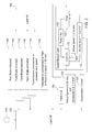
- the vehicle deceleration warning system 10 includes a transmission shift position sensor 14, a primary brake pedal activation sensor 16 operatively coupled to a primary brake pedal 17, a secondary brake switch activation sensor 18 operatively coupled to a secondary brake lever 19, a transmission gear sensor 20 and a vehicle or wheel speed sensor 22.
- a transmission gear signal may be provided by a transmission controller (not shown). Vehicle acceleration is calculated based on wheel speed change over time.
- Signals from sensors 14, 16, 18, 19, 20, 22 are received by a microprocessor-based electronic control unit (ECU) 30.
- the ECU 30 is connected to an indicator light 32, which could be a brake light or a lamp separate from a brake light.
- the indicator light 32 could be a lamp at the top center of a cab (not shown) in order to improve visibility, since an implement could interfere with visibility of standard tractor brake lights.
- the ECU 30 controls activation of the indicator light 32 as a function of the signals from the sensors 14, 16, 18, 19, 20, 22.
- the ECU 30 thereby processes the signals from the sensors 14, 16, 18, 19, 20, 22 and controls activation of the indicator light 32 as indicated by the diagram of Fig. 2 .
- the conversion of the diagram of Fig. 2 into a standard language for implementing the algorithm described by the flow chart in a digital computer or microprocessor of ECU 30 will be evident to one with ordinary skill in the art.
- the indicator light 32 will be turned off as indicated by block 102.
- the indicator light 32 is on and the primary brake pedal 17 is de-activated (block 108), then the indicator light 32 will be turned off as indicated by block 102.
- a transmission is in a "powered zero" condition when the transmission has been put into a forward or reverse gear, but has zero speed.
- the indicator light 32 If the indicator light 32 is on and transmission is commanded to Park or Neutral or wheel speed is less than 50 meters per hour (block 116), then the indicator light 32 will be turned on by block 102.
- the indicator light 32 will be turned on as indicated by block 122. As a result, the indicator light 32 will turn on if deceleration is high only about a speed threshold of about 20 kph.
- a timer (blocks 128, 130) will hold the indicator light 32 on for a desired time period such as 5 seconds. When the timer period has elapsed (block 132), then the indicator light 32 will be turned off (block 102).
- the indicator light 32 will be turned off (block 102). This occurs without any time delay so that the indicator light is immediately turned off if the vehicle accelerates.
- vehicle deceleration warning system 10 which controls a brake light or an indicator light as a function of vehicle deceleration and as a function of normal service brake pedal or secondary brake lever operation.
- Different deceleration rates and thresholds may be used for different transmission combinations including, infinitely variable, power shift, as well as others.
- the ECU 30 analyzes operator inputs and vehicle conditions, and determines the status of service brakes, secondary brakes, transmission powered zero condition, or if the agricultural tractor is decelerating due to hand throttle position, foot throttle position, or if transmission speed decreasing (due to gear change, or transmission control pulled rearward to slowdown).
- the ECU 30 illuminates an indicator light or brake light when the service brake or secondary brake is actuated, and turns it off when these inputs return to a neutral state.
- the indicator light 32 will also be illuminated when the ECU 30 determines the vehicle has exceeded a minimum velocity threshold (indicating a transport condition) and is decelerating at a rate that crosses a predetermined value, and illumination will be maintained for fixed amount of time after the deceleration has been halted.
- the indicator light 32 will be illuminated when the transmission is put into a "powered zero" condition. This condition may occur when the vehicle is at a stoplight, stop sign or intersection, but the operator is not using the service brake nor secondary brake to keep the vehicle from moving. In this case the vehicle deceleration warning system 10 generates a warning signal to rearward approaching vehicles that the vehicle is slowing or stopped.
Landscapes
- Engineering & Computer Science (AREA)
- Mechanical Engineering (AREA)
- Lighting Device Outwards From Vehicle And Optical Signal (AREA)
Abstract
A vehicle deceleration warning system (10) comprises a wheel speed sensor (22) for generating a wheel speed signal and an indicator light (32). An electronic control unit (30) receives the wheel speed signal and controls activation of the indicator light (32). The electronic control unit (30) activates the indicator light (32) when the wheel speed signal represents deceleration of the vehicle.
Description
- The present invention relates to a vehicle deceleration warning system.
- Off-road vehicles, such as agricultural tractors, are also operated on roads and highways. It is known to activate brake lights using a sensor on brake pedals to sense when the brake pedals have been displaced from a neutral position. However, an operator can slow down such a vehicle without using the brakes. When an agricultural tractor is operated in this manner, the brake lights will not be illuminated to signal to rear approaching vehicles that the agricultural tractor is slowing or stopping. It is desired to provide such vehicles with a system for signaling deceleration, even when the brakes are not being activated.
- This and other objects are achieved by the present invention, wherein a vehicle deceleration warning system is provided. The vehicle deceleration warning system comprises a wheel speed sensor for generating a wheel speed signal and an indicator light. An electronic control unit receives the wheel speed signal and controls activation of the indicator light. The electronic control unit activates the indicator light when the wheel speed signal represents deceleration of the vehicle.
- For a complete understanding of the objects, techniques, and structure of the invention reference should be made to the following detailed description and accompanying drawings:
- Fig. 1
- is a schematic diagram of a vehicle deceleration warning system embodying the invention,
- Fig. 2
- is a diagram illustrating the functions performed by an ECU of the vehicle deceleration warning system of
Fig. 1 . - Referring to
Fig. 1 , the vehicledeceleration warning system 10 includes a transmissionshift position sensor 14, a primary brakepedal activation sensor 16 operatively coupled to aprimary brake pedal 17, a secondary brakeswitch activation sensor 18 operatively coupled to asecondary brake lever 19, atransmission gear sensor 20 and a vehicle orwheel speed sensor 22. A transmission gear signal may be provided by a transmission controller (not shown). Vehicle acceleration is calculated based on wheel speed change over time. - Signals from
sensors indicator light 32, which could be a brake light or a lamp separate from a brake light. Theindicator light 32 could be a lamp at the top center of a cab (not shown) in order to improve visibility, since an implement could interfere with visibility of standard tractor brake lights. TheECU 30 controls activation of theindicator light 32 as a function of the signals from thesensors - The
ECU 30 thereby processes the signals from thesensors indicator light 32 as indicated by the diagram ofFig. 2 . The conversion of the diagram ofFig. 2 into a standard language for implementing the algorithm described by the flow chart in a digital computer or microprocessor ofECU 30 will be evident to one with ordinary skill in the art. - Following initialization at
block 100, theindicator light 32 will be turned off as indicated byblock 102. - If the
primary brake pedal 17 is activated (block 104), then theindicator light 32 will be turned on as indicated byblock 106. - If the
indicator light 32 is on and theprimary brake pedal 17 is de-activated (block 108), then theindicator light 32 will be turned off as indicated byblock 102. - If the
secondary brake lever 19 is activated (block 110), then theindicator light 32 will be turned on as indicated byblock 106. - If the
indicator light 32 is on and thesecondary brake lever 19 is de-activated (block 112), then theindicator light 32 will be turned off byblock 102. - If the transmission is commanded to powered zero speed (block 114), then the
indicator light 32 will be turned on as indicated byblock 106. A transmission is in a "powered zero" condition when the transmission has been put into a forward or reverse gear, but has zero speed. - If the
indicator light 32 is on and transmission is commanded to Park or Neutral or wheel speed is less than 50 meters per hour (block 116), then theindicator light 32 will be turned on byblock 102. - Returning to
block 102, if theindicator light 32 is off and wheel speed is greater than or equal to a threshold speed such as 5.55 meters per second and acceleration is less than or equal to an acceleration threshold such as -1.3 m/sec2 (block 120), then theindicator light 32 will be turned on as indicated byblock 122. As a result, theindicator light 32 will turn on if deceleration is high only about a speed threshold of about 20 kph. - If the
indicator light 32 is on as a result ofblock 122 and wheel speed is less than a speed threshold of 0.15 m/sec (block 124) or if acceleration is greater than an acceleration threshold such as -1.2 m/sec2 (block 126), then a timer (blocks 128, 130) will hold theindicator light 32 on for a desired time period such as 5 seconds. When the timer period has elapsed (block 132), then theindicator light 32 will be turned off (block 102). - If acceleration is greater than a threshold such as 0 m/sec (block 134), then the
indicator light 32 will be turned off (block 102). This occurs without any time delay so that the indicator light is immediately turned off if the vehicle accelerates. - The result is a vehicle
deceleration warning system 10 which controls a brake light or an indicator light as a function of vehicle deceleration and as a function of normal service brake pedal or secondary brake lever operation. Different deceleration rates and thresholds may be used for different transmission combinations including, infinitely variable, power shift, as well as others. - Thus, the
ECU 30 analyzes operator inputs and vehicle conditions, and determines the status of service brakes, secondary brakes, transmission powered zero condition, or if the agricultural tractor is decelerating due to hand throttle position, foot throttle position, or if transmission speed decreasing (due to gear change, or transmission control pulled rearward to slowdown). The ECU 30 illuminates an indicator light or brake light when the service brake or secondary brake is actuated, and turns it off when these inputs return to a neutral state. Theindicator light 32 will also be illuminated when theECU 30 determines the vehicle has exceeded a minimum velocity threshold (indicating a transport condition) and is decelerating at a rate that crosses a predetermined value, and illumination will be maintained for fixed amount of time after the deceleration has been halted. - The
indicator light 32 will be illuminated when the transmission is put into a "powered zero" condition. This condition may occur when the vehicle is at a stoplight, stop sign or intersection, but the operator is not using the service brake nor secondary brake to keep the vehicle from moving. In this case the vehicledeceleration warning system 10 generates a warning signal to rearward approaching vehicles that the vehicle is slowing or stopped.
Claims (9)
- A vehicle deceleration warning system, comprising a wheel speed sensor (22) for generating a wheel speed signal; an indicator light (32); and an electronic control unit (30) which receives the wheel speed signal and controls activation of the indicator light (32), the electronic control unit (30) activating the indicator light (32) when the wheel speed signal represents deceleration of the vehicle.
- The vehicle deceleration warning system according to claim 1, characterized in that the indicator light (32) comprises a brake light.
- The vehicle deceleration warning system according to claim 1 or 2, characterized in that the electronic control unit (30) turns the indicator light (32) on if a transmission of the vehicle is commanded to a powered zero speed condition.
- The vehicle deceleration warning system according to at least one of claims 1 to 3, characterized in that the electronic control unit (30) turns the indicator light (32) off if a transmission of the vehicle is commanded to Park or Neutral condition.
- The vehicle deceleration warning system according to at least on of claims 1 to 4, characterized in that the electronic control unit (30) turns the indicator light (32) off if wheel speed exceeds a speed threshold.
- The vehicle deceleration warning system according to at least one of claims 1 to 5, characterized in that the electronic control unit (30) turns the indicator light (32) on if wheel speed is greater than a first speed threshold and vehicle acceleration is less than a first acceleration threshold.
- The vehicle deceleration warning system according to claim 6, characterized in that the electronic control unit (30) turns the indicator light (32) off after a predetermined time period if vehicle acceleration is greater than a second acceleration threshold.
- The vehicle deceleration warning system according to claim 6, characterized in that the electronic control unit (30) turns the indicator light (32) off immediately if vehicle acceleration is greater than zero.
- The vehicle deceleration warning system according to at least one of claims 1 to 8, characterized in that the electronic control unit (30) turns the indicator light (32) on if a primary brake pedal (17) and/or a secondary brake lever (19) is activated, and the electronic control unit (30) turns the indicator light (32) off if the primary brake pedal (17) and/or the secondary brake lever (19) is de-activated.
Applications Claiming Priority (1)
| Application Number | Priority Date | Filing Date | Title |
|---|---|---|---|
| US14/460,033 US20160046231A1 (en) | 2014-08-14 | 2014-08-14 | Vehicle deceleration warning system |
Publications (1)
| Publication Number | Publication Date |
|---|---|
| EP2985181A1 true EP2985181A1 (en) | 2016-02-17 |
Family
ID=53835328
Family Applications (1)
| Application Number | Title | Priority Date | Filing Date |
|---|---|---|---|
| EP15180593.4A Withdrawn EP2985181A1 (en) | 2014-08-14 | 2015-08-11 | Vehicle deceleration warning system |
Country Status (2)
| Country | Link |
|---|---|
| US (1) | US20160046231A1 (en) |
| EP (1) | EP2985181A1 (en) |
Families Citing this family (3)
| Publication number | Priority date | Publication date | Assignee | Title |
|---|---|---|---|---|
| US10315559B2 (en) | 2016-07-11 | 2019-06-11 | Jeffery Hammock | Systems, apparatus, and methods for signaling sudden deceleration |
| CN110871733B (en) * | 2018-08-29 | 2022-08-02 | 长城汽车股份有限公司 | Vehicle brake lamp control method, device and system and readable storage medium thereof |
| JP7567712B2 (en) * | 2021-07-30 | 2024-10-16 | トヨタ自動車株式会社 | Driving diagnosis device and driving diagnosis method |
Citations (5)
| Publication number | Priority date | Publication date | Assignee | Title |
|---|---|---|---|---|
| JPS5867533A (en) * | 1981-10-15 | 1983-04-22 | Toyoda Gosei Co Ltd | Speed reduction indicator for automobile |
| EP0440468A2 (en) * | 1990-01-31 | 1991-08-07 | Stephen Paul Mccarthy | Indicating system for a vehicle |
| US6239696B1 (en) * | 1999-03-30 | 2001-05-29 | New Holland North America, Inc. | Signal light system for agricultural equipment |
| US20020047778A1 (en) * | 2000-08-14 | 2002-04-25 | Ehrlich Rodney P. | Brake lamp illumination on a trailer by sensing wheel speed deceleration |
| US20090261963A1 (en) * | 2008-04-22 | 2009-10-22 | Ault Scott T | Vehicle Deceleration Warning System |
-
2014
- 2014-08-14 US US14/460,033 patent/US20160046231A1/en not_active Abandoned
-
2015
- 2015-08-11 EP EP15180593.4A patent/EP2985181A1/en not_active Withdrawn
Patent Citations (5)
| Publication number | Priority date | Publication date | Assignee | Title |
|---|---|---|---|---|
| JPS5867533A (en) * | 1981-10-15 | 1983-04-22 | Toyoda Gosei Co Ltd | Speed reduction indicator for automobile |
| EP0440468A2 (en) * | 1990-01-31 | 1991-08-07 | Stephen Paul Mccarthy | Indicating system for a vehicle |
| US6239696B1 (en) * | 1999-03-30 | 2001-05-29 | New Holland North America, Inc. | Signal light system for agricultural equipment |
| US20020047778A1 (en) * | 2000-08-14 | 2002-04-25 | Ehrlich Rodney P. | Brake lamp illumination on a trailer by sensing wheel speed deceleration |
| US20090261963A1 (en) * | 2008-04-22 | 2009-10-22 | Ault Scott T | Vehicle Deceleration Warning System |
Also Published As
| Publication number | Publication date |
|---|---|
| US20160046231A1 (en) | 2016-02-18 |
Similar Documents
| Publication | Publication Date | Title |
|---|---|---|
| CN103318176B (en) | A kind of control method of passenger vehicle self-adaption cruise system | |
| US7117077B2 (en) | Speed control with stop function | |
| KR101382786B1 (en) | Auto cruise downhill control for vehicle | |
| US10773647B2 (en) | Method for triggering an automatic emergency braking process with variable warning time period | |
| US7646290B2 (en) | Deceleration warning device and method for a motor vehicle | |
| JPH05246270A (en) | Method and apparatus for controlling vehicle speed and inter-vehicle distance | |
| GB2375190A (en) | Lane-keeping and speed regulating equipment for a motor vehicle | |
| US10953794B2 (en) | Alert device for vehicles | |
| SE1450938A1 (en) | Procedure and systems for safety improvement when driving a motor vehicle | |
| CN103978927A (en) | Automobile brake taillight automatic control system based on forward direction collision avoidance system | |
| JPH1142955A (en) | Vehicle travel control device | |
| US20160046231A1 (en) | Vehicle deceleration warning system | |
| KR20140091333A (en) | Vehicle control apparatus and vehicle control method | |
| DE10048102A1 (en) | Method for operating a driver assistance system for motor vehicles | |
| JP2009501105A (en) | Flashing switch for automobile with adaptive speed controller | |
| US10202072B2 (en) | Brake warning lamp system | |
| JPWO2006057070A1 (en) | Automotive control device | |
| KR100655744B1 (en) | Vehicle alarm | |
| FR2855481A1 (en) | ACTIVE PARKING ASSISTANCE SYSTEM FOR MOTOR VEHICLE | |
| JP4842347B2 (en) | Inter-vehicle distance control device | |
| CN204488778U (en) | Intelligence auxiliary braking system | |
| JP6506152B2 (en) | Vehicle device and computer program | |
| KR100217575B1 (en) | Automotive braking system | |
| WO2011061617A1 (en) | Brake light system for the signalling of the braking intensity of a vehicle | |
| KR200308410Y1 (en) | Emergency lamp auto flickering apparatus |
Legal Events
| Date | Code | Title | Description |
|---|---|---|---|
| PUAI | Public reference made under article 153(3) epc to a published international application that has entered the european phase |
Free format text: ORIGINAL CODE: 0009012 |
|
| AK | Designated contracting states |
Kind code of ref document: A1 Designated state(s): AL AT BE BG CH CY CZ DE DK EE ES FI FR GB GR HR HU IE IS IT LI LT LU LV MC MK MT NL NO PL PT RO RS SE SI SK SM TR |
|
| AX | Request for extension of the european patent |
Extension state: BA ME |
|
| STAA | Information on the status of an ep patent application or granted ep patent |
Free format text: STATUS: THE APPLICATION IS DEEMED TO BE WITHDRAWN |
|
| 18D | Application deemed to be withdrawn |
Effective date: 20160818 |