EP2985084A1 - Process for coating a substrate body - Google Patents
Process for coating a substrate body Download PDFInfo
- Publication number
- EP2985084A1 EP2985084A1 EP14180973.1A EP14180973A EP2985084A1 EP 2985084 A1 EP2985084 A1 EP 2985084A1 EP 14180973 A EP14180973 A EP 14180973A EP 2985084 A1 EP2985084 A1 EP 2985084A1
- Authority
- EP
- European Patent Office
- Prior art keywords
- coating
- piston
- liquid
- displacement body
- substrate
- Prior art date
- Legal status (The legal status is an assumption and is not a legal conclusion. Google has not performed a legal analysis and makes no representation as to the accuracy of the status listed.)
- Granted
Links
Images


Classifications
-
- B—PERFORMING OPERATIONS; TRANSPORTING
- B05—SPRAYING OR ATOMISING IN GENERAL; APPLYING FLUENT MATERIALS TO SURFACES, IN GENERAL
- B05D—PROCESSES FOR APPLYING FLUENT MATERIALS TO SURFACES, IN GENERAL
- B05D7/00—Processes, other than flocking, specially adapted for applying liquids or other fluent materials to particular surfaces or for applying particular liquids or other fluent materials
- B05D7/22—Processes, other than flocking, specially adapted for applying liquids or other fluent materials to particular surfaces or for applying particular liquids or other fluent materials to internal surfaces, e.g. of tubes
-
- B—PERFORMING OPERATIONS; TRANSPORTING
- B01—PHYSICAL OR CHEMICAL PROCESSES OR APPARATUS IN GENERAL
- B01J—CHEMICAL OR PHYSICAL PROCESSES, e.g. CATALYSIS OR COLLOID CHEMISTRY; THEIR RELEVANT APPARATUS
- B01J35/00—Catalysts, in general, characterised by their form or physical properties
- B01J35/19—Catalysts containing parts with different compositions
-
- B—PERFORMING OPERATIONS; TRANSPORTING
- B01—PHYSICAL OR CHEMICAL PROCESSES OR APPARATUS IN GENERAL
- B01J—CHEMICAL OR PHYSICAL PROCESSES, e.g. CATALYSIS OR COLLOID CHEMISTRY; THEIR RELEVANT APPARATUS
- B01J35/00—Catalysts, in general, characterised by their form or physical properties
- B01J35/50—Catalysts, in general, characterised by their form or physical properties characterised by their shape or configuration
- B01J35/56—Foraminous structures having flow-through passages or channels, e.g. grids or three-dimensional [3D] monoliths
-
- B—PERFORMING OPERATIONS; TRANSPORTING
- B01—PHYSICAL OR CHEMICAL PROCESSES OR APPARATUS IN GENERAL
- B01J—CHEMICAL OR PHYSICAL PROCESSES, e.g. CATALYSIS OR COLLOID CHEMISTRY; THEIR RELEVANT APPARATUS
- B01J37/00—Processes, in general, for preparing catalysts; Processes, in general, for activation of catalysts
- B01J37/02—Impregnation, coating or precipitation
- B01J37/0215—Coating
-
- B—PERFORMING OPERATIONS; TRANSPORTING
- B01—PHYSICAL OR CHEMICAL PROCESSES OR APPARATUS IN GENERAL
- B01J—CHEMICAL OR PHYSICAL PROCESSES, e.g. CATALYSIS OR COLLOID CHEMISTRY; THEIR RELEVANT APPARATUS
- B01J37/00—Processes, in general, for preparing catalysts; Processes, in general, for activation of catalysts
- B01J37/02—Impregnation, coating or precipitation
- B01J37/024—Multiple impregnation or coating
- B01J37/0246—Coatings comprising a zeolite
-
- B—PERFORMING OPERATIONS; TRANSPORTING
- B01—PHYSICAL OR CHEMICAL PROCESSES OR APPARATUS IN GENERAL
- B01J—CHEMICAL OR PHYSICAL PROCESSES, e.g. CATALYSIS OR COLLOID CHEMISTRY; THEIR RELEVANT APPARATUS
- B01J37/00—Processes, in general, for preparing catalysts; Processes, in general, for activation of catalysts
- B01J37/02—Impregnation, coating or precipitation
- B01J37/024—Multiple impregnation or coating
- B01J37/0248—Coatings comprising impregnated particles
-
- B—PERFORMING OPERATIONS; TRANSPORTING
- B05—SPRAYING OR ATOMISING IN GENERAL; APPLYING FLUENT MATERIALS TO SURFACES, IN GENERAL
- B05C—APPARATUS FOR APPLYING FLUENT MATERIALS TO SURFACES, IN GENERAL
- B05C3/00—Apparatus in which the work is brought into contact with a bulk quantity of liquid or other fluent material
- B05C3/02—Apparatus in which the work is brought into contact with a bulk quantity of liquid or other fluent material the work being immersed in the liquid or other fluent material
-
- B—PERFORMING OPERATIONS; TRANSPORTING
- B05—SPRAYING OR ATOMISING IN GENERAL; APPLYING FLUENT MATERIALS TO SURFACES, IN GENERAL
- B05C—APPARATUS FOR APPLYING FLUENT MATERIALS TO SURFACES, IN GENERAL
- B05C7/00—Apparatus specially designed for applying liquid or other fluent material to the inside of hollow work
- B05C7/04—Apparatus specially designed for applying liquid or other fluent material to the inside of hollow work the liquid or other fluent material flowing or being moved through the work; the work being filled with liquid or other fluent material and emptied
-
- B—PERFORMING OPERATIONS; TRANSPORTING
- B05—SPRAYING OR ATOMISING IN GENERAL; APPLYING FLUENT MATERIALS TO SURFACES, IN GENERAL
- B05D—PROCESSES FOR APPLYING FLUENT MATERIALS TO SURFACES, IN GENERAL
- B05D1/00—Processes for applying liquids or other fluent materials
- B05D1/18—Processes for applying liquids or other fluent materials performed by dipping
-
- C—CHEMISTRY; METALLURGY
- C04—CEMENTS; CONCRETE; ARTIFICIAL STONE; CERAMICS; REFRACTORIES
- C04B—LIME, MAGNESIA; SLAG; CEMENTS; COMPOSITIONS THEREOF, e.g. MORTARS, CONCRETE OR LIKE BUILDING MATERIALS; ARTIFICIAL STONE; CERAMICS; REFRACTORIES; TREATMENT OF NATURAL STONE
- C04B38/00—Porous mortars, concrete, artificial stone or ceramic ware; Preparation thereof
- C04B38/0006—Honeycomb structures
-
- C—CHEMISTRY; METALLURGY
- C04—CEMENTS; CONCRETE; ARTIFICIAL STONE; CERAMICS; REFRACTORIES
- C04B—LIME, MAGNESIA; SLAG; CEMENTS; COMPOSITIONS THEREOF, e.g. MORTARS, CONCRETE OR LIKE BUILDING MATERIALS; ARTIFICIAL STONE; CERAMICS; REFRACTORIES; TREATMENT OF NATURAL STONE
- C04B38/00—Porous mortars, concrete, artificial stone or ceramic ware; Preparation thereof
- C04B38/0006—Honeycomb structures
- C04B38/0012—Honeycomb structures characterised by the material used for sealing or plugging (some of) the channels of the honeycombs
-
- F—MECHANICAL ENGINEERING; LIGHTING; HEATING; WEAPONS; BLASTING
- F01—MACHINES OR ENGINES IN GENERAL; ENGINE PLANTS IN GENERAL; STEAM ENGINES
- F01N—GAS-FLOW SILENCERS OR EXHAUST APPARATUS FOR MACHINES OR ENGINES IN GENERAL; GAS-FLOW SILENCERS OR EXHAUST APPARATUS FOR INTERNAL-COMBUSTION ENGINES
- F01N3/00—Exhaust or silencing apparatus having means for purifying, rendering innocuous, or otherwise treating exhaust
- F01N3/02—Exhaust or silencing apparatus having means for purifying, rendering innocuous, or otherwise treating exhaust for cooling, or for removing solid constituents of, exhaust
- F01N3/021—Exhaust or silencing apparatus having means for purifying, rendering innocuous, or otherwise treating exhaust for cooling, or for removing solid constituents of, exhaust by means of filters
- F01N3/022—Exhaust or silencing apparatus having means for purifying, rendering innocuous, or otherwise treating exhaust for cooling, or for removing solid constituents of, exhaust by means of filters characterised by specially adapted filtering structure, e.g. honeycomb, mesh or fibrous
- F01N3/0222—Exhaust or silencing apparatus having means for purifying, rendering innocuous, or otherwise treating exhaust for cooling, or for removing solid constituents of, exhaust by means of filters characterised by specially adapted filtering structure, e.g. honeycomb, mesh or fibrous the structure being monolithic, e.g. honeycombs
-
- F—MECHANICAL ENGINEERING; LIGHTING; HEATING; WEAPONS; BLASTING
- F01—MACHINES OR ENGINES IN GENERAL; ENGINE PLANTS IN GENERAL; STEAM ENGINES
- F01N—GAS-FLOW SILENCERS OR EXHAUST APPARATUS FOR MACHINES OR ENGINES IN GENERAL; GAS-FLOW SILENCERS OR EXHAUST APPARATUS FOR INTERNAL-COMBUSTION ENGINES
- F01N3/00—Exhaust or silencing apparatus having means for purifying, rendering innocuous, or otherwise treating exhaust
- F01N3/08—Exhaust or silencing apparatus having means for purifying, rendering innocuous, or otherwise treating exhaust for rendering innocuous
- F01N3/10—Exhaust or silencing apparatus having means for purifying, rendering innocuous, or otherwise treating exhaust for rendering innocuous by thermal or catalytic conversion of noxious components of exhaust
- F01N3/24—Exhaust or silencing apparatus having means for purifying, rendering innocuous, or otherwise treating exhaust for rendering innocuous by thermal or catalytic conversion of noxious components of exhaust characterised by constructional aspects of converting apparatus
- F01N3/28—Construction of catalytic reactors
-
- B—PERFORMING OPERATIONS; TRANSPORTING
- B05—SPRAYING OR ATOMISING IN GENERAL; APPLYING FLUENT MATERIALS TO SURFACES, IN GENERAL
- B05D—PROCESSES FOR APPLYING FLUENT MATERIALS TO SURFACES, IN GENERAL
- B05D2254/00—Tubes
- B05D2254/04—Applying the material on the interior of the tube
-
- B—PERFORMING OPERATIONS; TRANSPORTING
- B05—SPRAYING OR ATOMISING IN GENERAL; APPLYING FLUENT MATERIALS TO SURFACES, IN GENERAL
- B05D—PROCESSES FOR APPLYING FLUENT MATERIALS TO SURFACES, IN GENERAL
- B05D2259/00—Applying the material to the internal surface of hollow articles other than tubes
-
- F—MECHANICAL ENGINEERING; LIGHTING; HEATING; WEAPONS; BLASTING
- F01—MACHINES OR ENGINES IN GENERAL; ENGINE PLANTS IN GENERAL; STEAM ENGINES
- F01N—GAS-FLOW SILENCERS OR EXHAUST APPARATUS FOR MACHINES OR ENGINES IN GENERAL; GAS-FLOW SILENCERS OR EXHAUST APPARATUS FOR INTERNAL-COMBUSTION ENGINES
- F01N2230/00—Combination of silencers and other devices
- F01N2230/06—Spark arresters
-
- F—MECHANICAL ENGINEERING; LIGHTING; HEATING; WEAPONS; BLASTING
- F01—MACHINES OR ENGINES IN GENERAL; ENGINE PLANTS IN GENERAL; STEAM ENGINES
- F01N—GAS-FLOW SILENCERS OR EXHAUST APPARATUS FOR MACHINES OR ENGINES IN GENERAL; GAS-FLOW SILENCERS OR EXHAUST APPARATUS FOR INTERNAL-COMBUSTION ENGINES
- F01N2510/00—Surface coverings
- F01N2510/06—Surface coverings for exhaust purification, e.g. catalytic reaction
Definitions
- the present invention is directed to a certain method of catalytically coating a honeycomb monolith, in particular a so-called flow-through monolith. These types of monoliths can quite precisely be coated by a method using an indirect coating via a displacement body. The present invention further improves this method through controlling the process by certain measures.
- One possibility for coating substrate bodies is to bring the openings on one side thereof into contact with the coating medium and to draw the liquid coating medium through the openings, e.g. channels, of the substrate by applying a vacuum to the opposite side of the substrate. If the intention is to coat the channels on only part of the length thereof, it is disadvantageous that different channels are coated over different lengths due to the inevitably individual flow profile which arises from channel to channel.
- the coating medium is forced into the channels by pressure against the force of gravity, there is then a need to check (generally by means of a sensor) when the liquid emerges at the top in the case of complete coating of the channels.
- the height of the liquid column of coating medium within the channels is usually determined by direct or indirect measurement through sensors (capacity sensor; visual sensor; IR-sensor; vibrational sensor).
- sensors captureacity sensor; visual sensor; IR-sensor; vibrational sensor.
- an inhomogeneous coating front within the channels of a monolith can result, e.g. if coating is started with an uneven slurry surface formed in the coating chamber below the monolith. The latter occurs, in particular, if fast coating speeds are applied and coating slurry tends to get turbulent while being pumped into the coating chamber within a short timeframe.
- a preferred coating apparatus and method where cylindrical support bodies, each having two end faces, a circumferential surface and an axial length L, further being traversed from the first end face to the second end face by a multiplicity of channels, are coated with a liquid coating media.
- the apparatus in question has a cylinder filled with a liquid and has a piston, wherein the liquid-filled cylinder communicates with a tank, in the interior of which a displacement body is arranged in such a way that, when the piston is moved, the displacement body is moved proportionally by the liquid.
- the tank communicates with the coating device for the substrate, thus the displacement body acts on the liquid coating medium, with the result that a proportional change in the level of liquid coating medium in the coating device is brought about (see Fig. 1 of that application).
- Two sensors are arranged on the same height in the coating device in order to check whether the position of the slurry surface in the coating chamber has reached a certain level.
- This speed is directly related to the velocity of the movement of the piston in the liquid-filled cylinder that communicates with the displacement body. If speed for i. and/or ii. is increased certain defects occur in the coating which may mean that the flow and pressure conditions in some channels of a substrate differ greatly from the other channels, the effect being that the liquid coating medium penetrates with considerably more or considerably less difficulty and is deposited either over a shorter or longer length of the individual channels under the coating conditions.
- gas bubbles can appear in the liquid coating media. Because of the sometimes very high viscosity of the coating slurry these gas bubbles survive and are carried towards the coating chamber and into the substrate monolith, which in turn lead to mentioned defects, e.g. to unevenly or non-uniformly coated products if the bubbles finally enter a channel of the monolith.
- the objective of the present invention is to dispense with this drawback.
- the aim of the present invention is to present a method for coating a monolithic substrate with an apparatus as depicted above without the fear of having inhomogeneous coating slurries, especially due to bubble formation in it.
- a process for coating a monolithic substrate should be proposed that allows to safely coat these monoliths with envisaged device in a minimum amount of time.
- liquid coating media which has a cylinder (102) filled with a liquid (103) and having a piston (101), wherein the liquid-filled cylinder (102) communicates with a tank (112), in the interior of which a displacement body (111) is arranged in such a way that, when the piston (101) is moved, the displacement body (111) is moved proportionally by the liquid (103), and the tank (112) communicates with the coating device (122) for the substrate, wherein the displacement body (111) acts on the liquid coating medium (113), with the result that a proportional change in the level of liquid coating medium (113) in the coating device (122) is brought about; the movement of the piston (101), which leads to deflation of the displacement body
- the appearance of bubbles is enhanced by applying too high an underpressure in the washcoat reservoir (112). If the velocity of the movement of the piston (101) in the backstroke phase is too high such disadvantageous underpressure may result. However, the generation of bubbles in the coating medium is strongly dependent also on the character of the slurry and the components being present therein. Hence, the threshold value for the velocity of the backstroke of the piston (101) which is not to be overshot has to be set individually for each coating medium (washcoat). The threshold value can be determined in preliminary trial experiments and then be applied accordingly to the controller unit (125) of the coating device.
- a velocity of the piston (101), which leads to deflation of the displacement body (111) (backstroke) can vary between 0.01-3, more preferably between 0.05-0.25 and most preferred between 0.08-0.2m/s.
- a main factor for bubble generation and, in particular, for bubble lifetime is the viscosity of the slurry that is coated onto the substrate body. If the viscosity is high bubbles tend to survive a considerably period of time and endanger their appearance in the coating chamber. Hence, taken the position that the coating time should be as low as possible in order to coat as much parts as possible in a certain period of time and advantageously keeping the backstroke of the piston (101) in the above time frame, the viscosity of the liquid coating medium (113) shall be between 2- 200 mPa*s.
- the velocity of the piston (101), which leads to deflation of the displacement body (111) (backstroke) is controlled in such a way that the piston is accelerated first and decelerated to the end of its backstroke.
- the profile of the velocity approaches a Gaussian distribution curve profile.
- the highest velocity of the backstroke of the piston (101) is not more than 0.5 times, preferably 1 times, and most preferably 5 times the velocity at a position of 10% of the way of the piston (101) after start of the backstroke.
- Checking and controlling the backstroke of the piston (101) can be done by devices known to the skilled worker.
- the movement of the piston generally, is controlled by the controller unit (125).
- the controller unit (125) can rely on stored data for managing the movement of the piston (101) according to the present invention.
- the movement of the piston (125) can also be done by certain sensors applied to the coating device, whereby the sensor used to control the velocity of the piston (101) is selected from the group consisting of pressure sensor, level sensor and conductivity sensor.
- a so-called in-process-control is used to manage the backstroke movement of the piston (101).
- a pressure sensor applied to the washcoat reservoir (112 in Fig. 1 ; 212 in Fig. 2 ) will receive a discontinuity in the pressure value measurement if bubbles occur in the washcoat slurry.
- this discontinuity of the pressure curve it is advantageous to take this discontinuity of the pressure curve as a point to control the velocity of the movement of the piston (101).
- Controlling is done in that the velocity of the piston (101) in the backstroke movement is lowered as soon as the discontinuity arises to at least minimize the appearance of gas bubbles in the washcoat slurry and/or the velocity is kept below this discontinuity point to avoid bubble formation at all.
- This type of controlling is greatly preferred and utmost advantageous in view of the fact that the washcoat and its physical properties may vary over the length of a production campaign. Often the viscosity and, as said earlier, the bubble generation tendency is changing throughout the period of production of a certain catalyst body. Through applying this in-process-control measure the risk of gas formation and thus of bubbles in the coating medium is greatly reduced.
- the substrate used (121, 221) is generally a hollow substrate which is composed of metals or ceramics and has at least one inner channel (110, 210, 310), generally a multiplicity of inner channels.
- the substrates are generally substantially cylindrical support bodies, which each have a cylinder axis, two end faces, a circumferential surface and an axial length L and are traversed from the first end face to the second end face by a multiplicity of channels.
- Such support bodies are often also referred to as honeycomb bodies.
- the substrates can be flow-through honeycomb bodies or monoliths but also wall-flow-filters.
- the substrate can be composed of, for example, cordierite, mullite, aluminum titanate, silicon carbide or metals such as steel or stainless steel.
- the substrate is advantageously a monolithic, cylindrically shaped catalyst support body and is traversed by a multiplicity of flow channels parallel to the cylinder axis for the exhaust gases from internal combustion engines.
- Such monolithic catalyst support bodies are used on a large scale for the production of automotive exhaust gas catalysts.
- the cross-sectional shape of the catalyst support bodies depends on the installation requirements on the motor vehicle. Catalyst bodies with a round cross section, an elliptical or a triangular or hexagonal cross section are widely used.
- the flow channels generally have a square, rectangular, hexagonal, triangular, rhomboedric or other cross section and are arranged in a narrowly spaced pattern over the entire cross section of the catalyst bodies.
- the channel or cell density of the flow channels generally varies between 10 and 250 cm -2 , depending on the application.
- catalyst support bodies with cell densities of about 62 cm -2 are still frequently used nowadays.
- the wall thicknesses, i.e. the thickness of the walls which separate the channels of the substrate from one another, are usually from about 0.005 cm to about 0.25 cm.
- the substrate is advantageously arranged on the coating device (122, 222) in a liquid-tight manner, it being possible to achieve this by means of at least one seal.
- the seal can be hollow and can be filled with gas or liquid as the substrate is mounted on or inserted into the coating device (122, 222), and thus can form a leak tight closure.
- the leak tightness of the joint can be checked by means of a pressure or flow sensor.
- the liquid coating medium (113, 213) is, for example, a suspension or dispersion for coating exhaust gas catalysts (flow-through monoliths or filters) for motor vehicles ("washcoat") which contains catalytically active components or precursors thereof and inorganic oxides such as aluminum oxide, titanium dioxide, zirconium oxide or a combination thereof, it being possible for the oxides to be doped with silicon or lanthanum, for example.
- Noble metals such as platinum, palladium, gold, rhodium, iridium, osmium, ruthenium and combinations thereof can also be used as catalytically active components.
- metals can also be present as alloys with one another or with other metals or as oxides.
- the metals can also be present as precursors, such as nitrates, sulfites or organyls of said noble metals and mixtures thereof, and, in particular, palladium nitrate, palladium sulfite, platinum nitrate, platinum sulfite or Pt(NH 3 ) 4 (NO 3 ) 2 can be used in the liquid coating medium.
- the catalytically active component can then be obtained from the precursor.
- a suspension or dispersion of an inorganic oxide can initially be used for coating, after which, in a subsequent coating step, a suspension or dispersion which contains one or more catalytically active components can be applied.
- a suspension or dispersion which contains one or more catalytically active components can be applied.
- the liquid coating medium it is also possible for the liquid coating medium to contain both of these components.
- the liquid coating medium often has a solids content of between 35% and 52%.
- the finished substrates i.e. coated and heat-treated or calcined substrates
- a particularly uniform coating which is characterized in that the coated lengths of the different channels differ from one another by no more than 5 mm, in particular 3 mm, this applying to at least 95% of all the channels of a substrate, advantageously at least 99% of all the channels of a substrate, in particular 100% of all the channels.
- the coated length of the channels is less than the axial length L.
- the uniform coating length has the advantage that it is possible in this way to introduce two coatings from the mutually opposite ends of the respective substrate.
- the coating length can be set as accurately and reliably as possible since, in this way, only a short length of the substrate has to be used for the spacing between the coatings, remaining uncoated and thus inoperative. It is thereby possible to achieve improved exhaust gas purification or to reduce the charging of the substrate with coating.
- the channel lengths coated with the first catalytically active coating and the second catalytically active coating are in each case less than the axial length L of the substrate and, in the case of at least 95% of the channels of a substrate, the channel lengths coated with the first catalytically active coating and the second catalytically active coating respectively differ by no more than 5 mm, preferably 3 mm, from one another, and wherein the spacing between the two coatings in the case of at least 95% of the channels of a substrate is no more than 5 mm, advantageously no more than 3 mm, in particular no more than 1 mm.
- Figures 3A and 3B show a coated substrate (300) of this kind.
- the substrate has two end faces (301), a circumferential surface (302) and a length (L) and is traversed by a multiplicity of channels (310) between the end faces.
- the channels are provided with a first coating (330) over a first partial length (303) and with a second coating (340) over a further partial length (305), indicated by thickened lines in figure 3A , which form two zones, provided respectively with a first and a second coating.
- the spacing (304) between the two zones (303, 305) is preferably minimized, for which purpose as uniform a coating length as possible is necessary in both zones (303, 305) in order to avoid overlapping.
- this coating-free spacing (304) is no more than 5 mm, advantageously no more than 3 mm, in particular no more than 1 mm.
- a substrate (300) with circular end faces is illustrated. It is, of course, also possible for the end faces to have rectangular, square, oval, triangular, hexagonal or other polygonal shapes, resulting in a corresponding different three-dimensional shape of the substrate, e.g. prismatic or cuboidal.
- the first and second coatings and their partial lengths provided with the first (330) and the second (340) coating can be the same or different, and can show a gap as noted above or can overlap at least to a certain extent.
- the first and second coatings are advantageously of different types.
- at least one of the coatings is an oxidation catalyst or an SCR catalyst.
- the first coating (330) is an SCR catalyst and the second coating (340) is an oxidation catalyst for the oxidation of NH 3 , HC, and CO.
- the oxidation catalyst contains a noble metal of group VIII of the periodic table of elements, such as platinum, palladium, ruthenium, rhodium, gold, iridium or mixtures thereof, advantageously on a porous, solid support, generally a porous inorganic oxide, such as aluminum oxide or silicon dioxide. Platinum on a porous aluminum oxide and/or zeolite as a support is particularly advantageous.
- This coating on the coated substrate generally contains 0.1 to 10 g/ft 3 , preferably 0.5 - 5 g/ft 3 of platinum.
- the SCR catalyst contains an oxide chosen from the group comprising titanium dioxide, vanadium pentoxide, tungsten trioxide, cerium oxide, zirconium oxide, or mixtures thereof.
- the SCR catalyst contains titanium dioxide as a matrix, up to 10% by weight of vanadium pentoxide and up to 20% by weight of tungsten trioxide.
- the first coating contains an SCR catalyst containing vanadium pentoxide and aluminum oxide, and the second coating contains an oxidation catalyst which contains platinum, gold, palladium and aluminum oxide.
- the second coating preferably contains 0.1 to 10 g/ft 3 , preferably 0.5 - 5 g/ft 3 of platinum, gold or a combination thereof.
- the first coating contains an SCR catalyst containing titanium dioxide, vanadium pentoxide and tungsten trioxide, and the second coating contains an oxidation catalyst which contains platinum and aluminum oxide and/or a zeolite.
- the second coating preferably contains 0.1 to 10 g/ft 3 , preferably 0.5 - 5 g/ft 3 of platinum.
- the first coating contains an SCR catalyst containing a composition of a zeolite or zeotype, e.g. a small pore molecular sieve such as chabazite or erionite or levyne or SAPO-34, in particular a molecular sieve exchanged with iron or copper
- the second coating contains an oxidation catalyst which comprises platinum and aluminum oxide and/or a zeolite as mentioned above.
- the second coating preferably contains 0.1 to 10 g/ft 3 , preferably 0.5 - 5 g/ft 3 of platinum.
- the first coating contains an SCR catalyst containing a chabazite zeolite exchanged with copper and having an ammonia storage capacity of at least 20 milliliters of ammonia per gram of catalyst material
- the second coating contains an oxidation catalyst which contains platinum and aluminum oxide and/or a zeolite like chabazite.
- the second coating preferably contains 0.1 to 10 g/ft 3 , preferably 0.5 - 5 g/ft 3 of platinum.
- filter substrates which are suitable for the production of exhaust gas filters for motor vehicles according to the present process, they preferably have a porosity of more than 40%, generally from 40% to 75%, in particular from 45% to 60%.
- the mean pore size is at least 7 ⁇ m, e.g. from 7 ⁇ m to 34 ⁇ m, preferably more than 10 ⁇ m, in particular from 10 ⁇ m to 20 ⁇ m or from 11 ⁇ m to 19 ⁇ m.
- Finished substrates suitable for the production of exhaust gas filters for motor vehicles which have a mean pore size of 11 to 33 ⁇ m and a porosity of 40% to 60% are particularly advantageous.
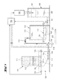
- Figure 1 shows an arrangement for coating channels (110) in a substrate (121), which has a piston (101), actuated by an actuator (100), in a cylinder (102), which is filled with liquid (103) and, through a connection (104) of the cylinder (102) to the displacement body (111), allows the actuation of the displacement body (111) in the tank (112), which is filled with liquid coating medium (113) and has two line sections (114, 116) with an interposed multiway valve (115) between the tank (112) and the coating device (122), wherein the coating device (122) is provided with the substrate (121) and with sensors (123) for determining the first level (130). Additional sensors (124) are used to monitor the displacement volume of the coating medium (113) and the state of the displacement body (111) in the tank (112).
- the values determined by the sensors (123, 124) are transmitted to a control unit (125) which, for its part, controls the actuator (100) and hence the piston (101).
- the multiway valve (115) switches the filling of the coating device (122) with coating medium (113) up to the first level (130) in the filling flow direction (117) and, on the other hand, after the second level (132) in the substrate (121) is reached, switches, in the return flow direction (118), the connection to the discharge pump (119) and to the connecting line (120) leading to a storage tank for excess coating medium (113) and for holding it ready for further use.
- All the control commands required for this purpose are preferably likewise output by the central control unit (125).
- Figure 2 shows an arrangement for coating channels (210) in a substrate (221), which has a piston (201), actuated by an actuator (200), in a cylinder (202), which is filled with liquid (203) and, through a connection (204) of the cylinder (202), communicates with the tank (212), in which the displacement body (211) is situated, which contains liquid coating medium (213) and is connected via two line sections (214, 216) with an interposed multiway valve (215) to the coating device (222), which is provided with a substrate (221) and sensors (223) for determining the first level (230) of coating medium (213).
- the additional sensors (224) on the tank (212) By means of the additional sensors (224) on the tank (212), the displacement volume of coating medium and the state of the displacement body (211) in the tank (212) are monitored. The values determined by the sensors (223, 224) are transmitted to a control unit (225) which, for its part, controls the actuator (200) and hence the piston (201).
- the multiway valve (215) switches the filling of the coating device (222) with coating medium (213) up to the first level (230) in the filling flow direction (217) and, on the other hand, after the second level (232) in the substrate (221) is reached, switches, in the return flow direction (218), the connection to the discharge pump (219) and to the connecting line (220) leading to a storage tank for excess coating medium (213) and for holding it ready for further use. All the control commands required for this purpose are preferably likewise output by the central control unit (225).
- Figures 3A and 3B show in perspective a substrate (300), which has a section broken away in three planes in the central part thereof to make it possible to see into the coating structure according to the invention.
- the substrate (300), which is coated in two partial length zones (303, 305), has two end faces (301), a circumferential surface (302) and a length (L) and is traversed by a multiplicity of channels (310) between the two end faces (301).
- a first coating (330) is applied to a first partial length zone (303) in the channels (310), while a further partial length zone (305) is provided with a second coating (340).
- FIG. 3B Between the two partial length zones (303) and (305) or between the two coatings (330) and (340) there is a coating-free zone (304), as figure 3B , in particular, shows on an enlarged scale.
Landscapes
- Chemical & Material Sciences (AREA)
- Engineering & Computer Science (AREA)
- Chemical Kinetics & Catalysis (AREA)
- Materials Engineering (AREA)
- Organic Chemistry (AREA)
- Wood Science & Technology (AREA)
- Life Sciences & Earth Sciences (AREA)
- Ceramic Engineering (AREA)
- Combustion & Propulsion (AREA)
- Mechanical Engineering (AREA)
- General Engineering & Computer Science (AREA)
- Structural Engineering (AREA)
- Health & Medical Sciences (AREA)
- Toxicology (AREA)
- Catalysts (AREA)
- Application Of Or Painting With Fluid Materials (AREA)
- Coating Apparatus (AREA)
Abstract
Description
- The present invention is directed to a certain method of catalytically coating a honeycomb monolith, in particular a so-called flow-through monolith. These types of monoliths can quite precisely be coated by a method using an indirect coating via a displacement body. The present invention further improves this method through controlling the process by certain measures.
- It is well known in the field of combustion engines that fuel combustion is not complete and yield emissions of pollutants like unburned hydrocarbons (HC), carbon monoxide (CO), nitrogen oxides (NOx) and particulate matter (PM). In order to improve air quality, emission limit legislations are in place to achieve lower emissions of pollutants from stationary applications and from mobile sources. For mobile sources like passenger cars, primary measures enabled achieving decrease in the emission of pollutants. Improvement of fuel-air mixing as primary measure yielded considerable diminution of pollutants. However, due to more stringent legislations over the years, the use of heterogeneous catalysts has been made inevitable.
- An important aspect of producing these heterogeneous catalysts is the precise coating of substrate bodies used in terms of, e.g. coating length, coating quantity applied, evenness of coating layer, and uniformity of coating length. In order to achieve this, up to now several coating strategies have been employed that try to provide well coated monolithic bodies, advantageously in as few time as possible.
- One possibility for coating substrate bodies is to bring the openings on one side thereof into contact with the coating medium and to draw the liquid coating medium through the openings, e.g. channels, of the substrate by applying a vacuum to the opposite side of the substrate. If the intention is to coat the channels on only part of the length thereof, it is disadvantageous that different channels are coated over different lengths due to the inevitably individual flow profile which arises from channel to channel.
- If the coating medium is forced into the channels by pressure against the force of gravity, there is then a need to check (generally by means of a sensor) when the liquid emerges at the top in the case of complete coating of the channels. In the case of coating over part of the length of the channels, the height of the liquid column of coating medium within the channels is usually determined by direct or indirect measurement through sensors (capacity sensor; visual sensor; IR-sensor; vibrational sensor). However, also in this case an inhomogeneous coating front within the channels of a monolith can result, e.g. if coating is started with an uneven slurry surface formed in the coating chamber below the monolith. The latter occurs, in particular, if fast coating speeds are applied and coating slurry tends to get turbulent while being pumped into the coating chamber within a short timeframe.
- In DE102010007499A1 a preferred coating apparatus and method is disclosed where cylindrical support bodies, each having two end faces, a circumferential surface and an axial length L, further being traversed from the first end face to the second end face by a multiplicity of channels, are coated with a liquid coating media. The apparatus in question has a cylinder filled with a liquid and has a piston, wherein the liquid-filled cylinder communicates with a tank, in the interior of which a displacement body is arranged in such a way that, when the piston is moved, the displacement body is moved proportionally by the liquid. The tank communicates with the coating device for the substrate, thus the displacement body acts on the liquid coating medium, with the result that a proportional change in the level of liquid coating medium in the coating device is brought about (see
Fig. 1 of that application). Two sensors are arranged on the same height in the coating device in order to check whether the position of the slurry surface in the coating chamber has reached a certain level. - In view to accelerate the coating process even further with this type of coating device a factor is the speed with which
- i. the coating liquid can be submitted into the substrate, and
- ii. the displacement body can be deflated again in order to let new coating media flow into the coating tank.
- This speed is directly related to the velocity of the movement of the piston in the liquid-filled cylinder that communicates with the displacement body. If speed for i. and/or ii. is increased certain defects occur in the coating which may mean that the flow and pressure conditions in some channels of a substrate differ greatly from the other channels, the effect being that the liquid coating medium penetrates with considerably more or considerably less difficulty and is deposited either over a shorter or longer length of the individual channels under the coating conditions.
- E.g., it has been discovered that gas bubbles can appear in the liquid coating media. Because of the sometimes very high viscosity of the coating slurry these gas bubbles survive and are carried towards the coating chamber and into the substrate monolith, which in turn lead to mentioned defects, e.g. to unevenly or non-uniformly coated products if the bubbles finally enter a channel of the monolith.
- The objective of the present invention is to dispense with this drawback. In particular, the aim of the present invention is to present a method for coating a monolithic substrate with an apparatus as depicted above without the fear of having inhomogeneous coating slurries, especially due to bubble formation in it. In addition, a process for coating a monolithic substrate should be proposed that allows to safely coat these monoliths with envisaged device in a minimum amount of time.
- This objective is achieved by applying a process of
present claim 1. Dependent claims are directed towards advantageous aspects of the present invention. - In that;
in a process for coating substrates for the production of exhaust gas purification catalysts, particularly for motor vehicles, which are cylindrical support bodies and each have two end faces (301), a circumferential surface (302) and an axial length L and are traversed from the first end face to the second end face by a multiplicity of channels (310), with liquid coating media, which has a cylinder (102) filled with a liquid (103) and having a piston (101), wherein the liquid-filled cylinder (102) communicates with a tank (112), in the interior of which a displacement body (111) is arranged in such a way that, when the piston (101) is moved, the displacement body (111) is moved proportionally by the liquid (103), and the tank (112) communicates with the coating device (122) for the substrate, wherein the displacement body (111) acts on the liquid coating medium (113), with the result that a proportional change in the level of liquid coating medium (113) in the coating device (122) is brought about;
the movement of the piston (101), which leads to deflation of the displacement body (111) (so-called: backstroke), is controlled in such a way that a certain velocity of the piston (101) is not overshot, the present invention rather surprisingly but nonetheless advantageously solves the problems associated with instant coating technology and greatly decreases the risk of gas formation within the washcoat slurry. - The appearance of bubbles, obviously, is enhanced by applying too high an underpressure in the washcoat reservoir (112). If the velocity of the movement of the piston (101) in the backstroke phase is too high such disadvantageous underpressure may result. However, the generation of bubbles in the coating medium is strongly dependent also on the character of the slurry and the components being present therein. Hence, the threshold value for the velocity of the backstroke of the piston (101) which is not to be overshot has to be set individually for each coating medium (washcoat). The threshold value can be determined in preliminary trial experiments and then be applied accordingly to the controller unit (125) of the coating device. In tests it has been determined that for usual washcoat slurries a velocity of the piston (101), which leads to deflation of the displacement body (111) (backstroke) can vary between 0.01-3, more preferably between 0.05-0.25 and most preferred between 0.08-0.2m/s.
- A main factor for bubble generation and, in particular, for bubble lifetime is the viscosity of the slurry that is coated onto the substrate body. If the viscosity is high bubbles tend to survive a considerably period of time and endanger their appearance in the coating chamber. Hence, taken the position that the coating time should be as low as possible in order to coat as much parts as possible in a certain period of time and advantageously keeping the backstroke of the piston (101) in the above time frame, the viscosity of the liquid coating medium (113) shall be between 2- 200 mPa*s.
- It has further turned out that a certain kind of profile of the backstroke movement of the piston (101) has an influence on the generation of gases in the washcoat slurry. Several such profiles can come to the mind of the skilled worker in this regard. However, in a preferred aspect the velocity of the piston (101), which leads to deflation of the displacement body (111) (backstroke) is controlled in such a way that the piston is accelerated first and decelerated to the end of its backstroke. In a more preferred mode, the profile of the velocity approaches a Gaussian distribution curve profile. In a very preferred embodiment, the highest velocity of the backstroke of the piston (101) is not more than 0.5 times, preferably 1 times, and most preferably 5 times the velocity at a position of 10% of the way of the piston (101) after start of the backstroke.
- Checking and controlling the backstroke of the piston (101) can be done by devices known to the skilled worker. The movement of the piston, generally, is controlled by the controller unit (125). Normally, the controller unit (125) can rely on stored data for managing the movement of the piston (101) according to the present invention. However, the movement of the piston (125) can also be done by certain sensors applied to the coating device, whereby the sensor used to control the velocity of the piston (101) is selected from the group consisting of pressure sensor, level sensor and conductivity sensor.
- In a very preferred embodiment of the present invention a so-called in-process-control is used to manage the backstroke movement of the piston (101). When moving back the piston (101) into its initial position, and thus producing an underpressure in the liquid coating slurry, a pressure sensor applied to the washcoat reservoir (112 in
Fig. 1 ; 212 inFig. 2 ) will receive a discontinuity in the pressure value measurement if bubbles occur in the washcoat slurry. Hence, it is advantageous to take this discontinuity of the pressure curve as a point to control the velocity of the movement of the piston (101). Controlling is done in that the velocity of the piston (101) in the backstroke movement is lowered as soon as the discontinuity arises to at least minimize the appearance of gas bubbles in the washcoat slurry and/or the velocity is kept below this discontinuity point to avoid bubble formation at all. This type of controlling is greatly preferred and utmost advantageous in view of the fact that the washcoat and its physical properties may vary over the length of a production campaign. Often the viscosity and, as said earlier, the bubble generation tendency is changing throughout the period of production of a certain catalyst body. Through applying this in-process-control measure the risk of gas formation and thus of bubbles in the coating medium is greatly reduced. - For performing the coating process of the present invention it is referred to the disclosure
DE102010007499A1 , which is incorporated herein in its entirety, at least in view of the aspects directed to the device features. In particular, the preferred characteristics of the process mentioned inDE102010007499A1 apply mutatis mutandis also to the process of present invention. It is likewise noted that references made herein toFig. 1 are deemed to be made toFig. 2 accordingly for the same aspect. It has to be noted though thatFig. 2 is different fromFig. 1 in that deflation and inflation of the displacement body (111) or (211) are anticyclic. Hence, when talking about an embodiment according toFig. 2 in the above text "deflation" has to be exchanged for "inflation". Other aspects may receive a similar interpretation according to the above said. - The substrate used (121, 221) is generally a hollow substrate which is composed of metals or ceramics and has at least one inner channel (110, 210, 310), generally a multiplicity of inner channels. The substrates are generally substantially cylindrical support bodies, which each have a cylinder axis, two end faces, a circumferential surface and an axial length L and are traversed from the first end face to the second end face by a multiplicity of channels. Such support bodies are often also referred to as honeycomb bodies. In particular, the substrates can be flow-through honeycomb bodies or monoliths but also wall-flow-filters. The substrate can be composed of, for example, cordierite, mullite, aluminum titanate, silicon carbide or metals such as steel or stainless steel. The substrate is advantageously a monolithic, cylindrically shaped catalyst support body and is traversed by a multiplicity of flow channels parallel to the cylinder axis for the exhaust gases from internal combustion engines. Such monolithic catalyst support bodies are used on a large scale for the production of automotive exhaust gas catalysts. The cross-sectional shape of the catalyst support bodies depends on the installation requirements on the motor vehicle. Catalyst bodies with a round cross section, an elliptical or a triangular or hexagonal cross section are widely used. The flow channels generally have a square, rectangular, hexagonal, triangular, rhomboedric or other cross section and are arranged in a narrowly spaced pattern over the entire cross section of the catalyst bodies. The channel or cell density of the flow channels generally varies between 10 and 250 cm-2, depending on the application. For exhaust gas purification on motor cars, catalyst support bodies with cell densities of about 62 cm-2 are still frequently used nowadays. The wall thicknesses, i.e. the thickness of the walls which separate the channels of the substrate from one another, are usually from about 0.005 cm to about 0.25 cm.
- The substrate is advantageously arranged on the coating device (122, 222) in a liquid-tight manner, it being possible to achieve this by means of at least one seal. The seal can be hollow and can be filled with gas or liquid as the substrate is mounted on or inserted into the coating device (122, 222), and thus can form a leak tight closure. The leak tightness of the joint can be checked by means of a pressure or flow sensor.
- The liquid coating medium (113, 213) is, for example, a suspension or dispersion for coating exhaust gas catalysts (flow-through monoliths or filters) for motor vehicles ("washcoat") which contains catalytically active components or precursors thereof and inorganic oxides such as aluminum oxide, titanium dioxide, zirconium oxide or a combination thereof, it being possible for the oxides to be doped with silicon or lanthanum, for example. Oxides of vanadium, chromium, manganese, iron, cobalt, copper, zinc, nickel or rare earth metals such as lanthanum, cerium, praseodymium, neodymium, promethium, samarium, europium, gadolinium, terbium, dysprosium, holmium, erbium, thulium, ytterbium or combinations thereof can be used as catalytically active components. Noble metals such as platinum, palladium, gold, rhodium, iridium, osmium, ruthenium and combinations thereof can also be used as catalytically active components. These metals can also be present as alloys with one another or with other metals or as oxides. The metals can also be present as precursors, such as nitrates, sulfites or organyls of said noble metals and mixtures thereof, and, in particular, palladium nitrate, palladium sulfite, platinum nitrate, platinum sulfite or Pt(NH3)4(NO3)2 can be used in the liquid coating medium. By calcination at about 400°C to about 700°C, the catalytically active component can then be obtained from the precursor. To coat a substrate for the production of automotive exhaust gas catalysts, a suspension or dispersion of an inorganic oxide can initially be used for coating, after which, in a subsequent coating step, a suspension or dispersion which contains one or more catalytically active components can be applied. However, it is also possible for the liquid coating medium to contain both of these components. The liquid coating medium often has a solids content of between 35% and 52%.
- The finished substrates (i.e. coated and heat-treated or calcined substrates), which are suitable for the production of exhaust gas catalysts for motor vehicles, have a particularly uniform coating, which is characterized in that the coated lengths of the different channels differ from one another by no more than 5 mm, in particular 3 mm, this applying to at least 95% of all the channels of a substrate, advantageously at least 99% of all the channels of a substrate, in particular 100% of all the channels. In this case, the coated length of the channels is less than the axial length L. The uniform coating length has the advantage that it is possible in this way to introduce two coatings from the mutually opposite ends of the respective substrate.
- If these coatings are different and have to be separate from one another (e.g. because the coating components react with one another in an unwanted way or impair each other in their action), a spacing must be maintained and reliably ensured between the two coatings. It is advantageous here if the coating length can be set as accurately and reliably as possible since, in this way, only a short length of the substrate has to be used for the spacing between the coatings, remaining uncoated and thus inoperative. It is thereby possible to achieve improved exhaust gas purification or to reduce the charging of the substrate with coating.
- It is thus possible, in a particularly advantageous way, to use the method of the invention to obtain a coated substrate for the production of exhaust gas catalysts for motor vehicles in which the channels are provided on the inside with at least one first catalytically active coating and on the outlet with one second catalytically active coating, the channel lengths coated with the first catalytically active coating and the second catalytically active coating are in each case less than the axial length L of the substrate and, in the case of at least 95% of the channels of a substrate, the channel lengths coated with the first catalytically active coating and the second catalytically active coating respectively differ by no more than 5 mm, preferably 3 mm, from one another, and wherein the spacing between the two coatings in the case of at least 95% of the channels of a substrate is no more than 5 mm, advantageously no more than 3 mm, in particular no more than 1 mm.
-
Figures 3A and 3B show a coated substrate (300) of this kind. The substrate has two end faces (301), a circumferential surface (302) and a length (L) and is traversed by a multiplicity of channels (310) between the end faces. In this case, the channels are provided with a first coating (330) over a first partial length (303) and with a second coating (340) over a further partial length (305), indicated by thickened lines infigure 3A , which form two zones, provided respectively with a first and a second coating. The spacing (304) between the two zones (303, 305) is preferably minimized, for which purpose as uniform a coating length as possible is necessary in both zones (303, 305) in order to avoid overlapping. According to this invention, this coating-free spacing (304) is no more than 5 mm, advantageously no more than 3 mm, in particular no more than 1 mm. In thisfigure 3A , a substrate (300) with circular end faces is illustrated. It is, of course, also possible for the end faces to have rectangular, square, oval, triangular, hexagonal or other polygonal shapes, resulting in a corresponding different three-dimensional shape of the substrate, e.g. prismatic or cuboidal. The first and second coatings and their partial lengths provided with the first (330) and the second (340) coating can be the same or different, and can show a gap as noted above or can overlap at least to a certain extent. - The first and second coatings are advantageously of different types. In one embodiment of the invention, at least one of the coatings is an oxidation catalyst or an SCR catalyst. In a particularly advantageous embodiment of the invention, the first coating (330) is an SCR catalyst and the second coating (340) is an oxidation catalyst for the oxidation of NH3, HC, and CO.
- It is advantageous if the oxidation catalyst contains a noble metal of group VIII of the periodic table of elements, such as platinum, palladium, ruthenium, rhodium, gold, iridium or mixtures thereof, advantageously on a porous, solid support, generally a porous inorganic oxide, such as aluminum oxide or silicon dioxide. Platinum on a porous aluminum oxide and/or zeolite as a support is particularly advantageous. This coating on the coated substrate generally contains 0.1 to 10 g/ft3, preferably 0.5 - 5 g/ft3 of platinum.
- In a specific embodiment of the invention, the SCR catalyst contains an oxide chosen from the group comprising titanium dioxide, vanadium pentoxide, tungsten trioxide, cerium oxide, zirconium oxide, or mixtures thereof. In another specific embodiment of the invention, the SCR catalyst contains titanium dioxide as a matrix, up to 10% by weight of vanadium pentoxide and up to 20% by weight of tungsten trioxide. In another specific embodiment of the invention, the first coating contains an SCR catalyst containing vanadium pentoxide and aluminum oxide, and the second coating contains an oxidation catalyst which contains platinum, gold, palladium and aluminum oxide. In this case, the second coating preferably contains 0.1 to 10 g/ft3, preferably 0.5 - 5 g/ft3 of platinum, gold or a combination thereof. In another specific embodiment of the invention, the first coating contains an SCR catalyst containing titanium dioxide, vanadium pentoxide and tungsten trioxide, and the second coating contains an oxidation catalyst which contains platinum and aluminum oxide and/or a zeolite. In this case, the second coating preferably contains 0.1 to 10 g/ft3, preferably 0.5 - 5 g/ft3 of platinum.
- In another specific embodiment of the invention, the first coating contains an SCR catalyst containing a composition of a zeolite or zeotype, e.g. a small pore molecular sieve such as chabazite or erionite or levyne or SAPO-34, in particular a molecular sieve exchanged with iron or copper, and the second coating contains an oxidation catalyst which comprises platinum and aluminum oxide and/or a zeolite as mentioned above. In this case, the second coating preferably contains 0.1 to 10 g/ft3, preferably 0.5 - 5 g/ft3 of platinum.
- In another specific embodiment of the invention, the first coating contains an SCR catalyst containing a chabazite zeolite exchanged with copper and having an ammonia storage capacity of at least 20 milliliters of ammonia per gram of catalyst material, and the second coating contains an oxidation catalyst which contains platinum and aluminum oxide and/or a zeolite like chabazite. In this case, the second coating preferably contains 0.1 to 10 g/ft3, preferably 0.5 - 5 g/ft3 of platinum.
- In view of filter substrates, which are suitable for the production of exhaust gas filters for motor vehicles according to the present process, they preferably have a porosity of more than 40%, generally from 40% to 75%, in particular from 45% to 60%. The mean pore size is at least 7 µm, e.g. from 7 µm to 34 µm, preferably more than 10 µm, in particular from 10 µm to 20 µm or from 11 µm to 19 µm. Finished substrates suitable for the production of exhaust gas filters for motor vehicles which have a mean pore size of 11 to 33 µm and a porosity of 40% to 60% are particularly advantageous.
-
-
Fig.1 :- 100
- actuator
- 101
- piston
- 102
- cylinder
- 103
- liquid
- 104
- connection
- 110
- channels - in the
substrate 121 - 111
- displacement body
- 112
- tank
- 113
- coating medium
- 114
- line section
- 115
- multiway valve
- 116
- line section
- 117
- filling flow direction
- 118
- return flow direction to remove
coating medium 113 - 119
- discharge pump
- 120
- connecting line leading to the reservoir for the coating medium
- 121
- substrate
- 122
- coating device
- 123
- sensor for detecting the
level 130 - 124
- sensor for monitoring the position of the
displacement body 111 - 125
- control unit
- 130
- first level - of 113 in the
coating device 122 - 132
- second level - of 113 in the
substrate 121
-
Fig. 2 :- 200
- actuator
- 201
- piston
- 202
- cylinder
- 203
- liquid
- 204
- connection
- 210
- channels - in the
substrate 221 - 211
- displacement body
- 212
- tank
- 213
- coating medium
- 214
- line section
- 215
- multiway valve
- 216
- line section
- 217
- filling direction
- 218
- extraction flow direction of 213
- 219
- discharge and extraction pump
- 220
- connecting line leading to the reservoir for
excess coating medium 213 - 221
- substrate
- 222
- coating device
- 223
- sensor for detecting the
level 230 - 224
- sensor for monitoring the position of the displacement body
- 225
- control unit
- 230
- first level - in the
coating device 222 - 232
- second level - in the
substrate 221
-
Fig. 3 :- 300
- substrate
- 301
- end face
- 302
- circumderential surface
- 303
- firt partial length zone
- 304
- spacing - between the two
partial lengths - 305
- second partial length zone
- 310
- channels - in the
substrate 300 - 330
- first coating - in the
channels 310 - 340
- second coating - in the
channels 310 - L
- total length of the
substrate 300
-
Figure 1 shows an arrangement for coating channels (110) in a substrate (121), which has a piston (101), actuated by an actuator (100), in a cylinder (102), which is filled with liquid (103) and, through a connection (104) of the cylinder (102) to the displacement body (111), allows the actuation of the displacement body (111) in the tank (112), which is filled with liquid coating medium (113) and has two line sections (114, 116) with an interposed multiway valve (115) between the tank (112) and the coating device (122), wherein the coating device (122) is provided with the substrate (121) and with sensors (123) for determining the first level (130). Additional sensors (124) are used to monitor the displacement volume of the coating medium (113) and the state of the displacement body (111) in the tank (112). - The values determined by the sensors (123, 124) are transmitted to a control unit (125) which, for its part, controls the actuator (100) and hence the piston (101).
- On the one hand, the multiway valve (115) switches the filling of the coating device (122) with coating medium (113) up to the first level (130) in the filling flow direction (117) and, on the other hand, after the second level (132) in the substrate (121) is reached, switches, in the return flow direction (118), the connection to the discharge pump (119) and to the connecting line (120) leading to a storage tank for excess coating medium (113) and for holding it ready for further use.
- All the control commands required for this purpose are preferably likewise output by the central control unit (125).
-
Figure 2 shows an arrangement for coating channels (210) in a substrate (221), which has a piston (201), actuated by an actuator (200), in a cylinder (202), which is filled with liquid (203) and, through a connection (204) of the cylinder (202), communicates with the tank (212), in which the displacement body (211) is situated, which contains liquid coating medium (213) and is connected via two line sections (214, 216) with an interposed multiway valve (215) to the coating device (222), which is provided with a substrate (221) and sensors (223) for determining the first level (230) of coating medium (213). - By means of the additional sensors (224) on the tank (212), the displacement volume of coating medium and the state of the displacement body (211) in the tank (212) are monitored. The values determined by the sensors (223, 224) are transmitted to a control unit (225) which, for its part, controls the actuator (200) and hence the piston (201).
- On the one hand, the multiway valve (215) switches the filling of the coating device (222) with coating medium (213) up to the first level (230) in the filling flow direction (217) and, on the other hand, after the second level (232) in the substrate (221) is reached, switches, in the return flow direction (218), the connection to the discharge pump (219) and to the connecting line (220) leading to a storage tank for excess coating medium (213) and for holding it ready for further use. All the control commands required for this purpose are preferably likewise output by the central control unit (225).
-
Figures 3A and 3B show in perspective a substrate (300), which has a section broken away in three planes in the central part thereof to make it possible to see into the coating structure according to the invention. - The substrate (300), which is coated in two partial length zones (303, 305), has two end faces (301), a circumferential surface (302) and a length (L) and is traversed by a multiplicity of channels (310) between the two end faces (301).
- A first coating (330) is applied to a first partial length zone (303) in the channels (310), while a further partial length zone (305) is provided with a second coating (340).
- Between the two partial length zones (303) and (305) or between the two coatings (330) and (340) there is a coating-free zone (304), as
figure 3B , in particular, shows on an enlarged scale.
Claims (5)
- A process for coating substrates for the production of exhaust gas purification catalysts, particularly for motor vehicles, which are cylindrical support bodies and each have two end faces (301), a circumferential surface (302) and an axial length L and are traversed from the first end face to the second end face by a multiplicity of channels (310), with liquid coating media, which has a cylinder (102) filled with a liquid (103) and having a piston (101), wherein the liquid-filled cylinder (102) communicates with a tank (112), in the interior of which a displacement body (111) is arranged in such a way that, when the piston (101) is moved, the displacement body (111) is moved proportionally by the liquid (103), and the tank (112) communicates with the coating device (122) for the substrate, wherein the displacement body (111) acts on the liquid coating medium (113), with the result that a proportional change in the level of liquid coating medium (113) in the coating device (122) is brought about,
wherein the movement of the piston (101), which leads to deflation of the displacement body (111) is controlled in such a way that a certain velocity of the piston (101) is not overshot. - Process according to claim 1,
characterized in that,
the velocity of the piston (101) ), which leads to deflation of the displacement body (111) is between 0.01 - 3 m/s. - Process according to claim 2,
characterized in that,
the viscosity of the liquid coating medium (113) is between 2 - 200mPa*s. - Process according to anyone of the preceding claims,
characterized in that,
the velocity of the piston (101), which leads to deflation of the displacement body (111) is controlled in such a way that the piston is accelerated first and decelerated to the end of its backstroke. - Process according to anyone of the preceding claims,
characterized in that,
the sensor used to control the velocity of the piston (101) is selected from the group consisting of pressure sensor, optical sensor, conductivity sensor and vibration sensor.
Priority Applications (10)
| Application Number | Priority Date | Filing Date | Title |
|---|---|---|---|
| PL14180973T PL2985084T3 (en) | 2014-08-14 | 2014-08-14 | Process for coating a substrate body |
| EP14180973.1A EP2985084B1 (en) | 2014-08-14 | 2014-08-14 | Process for coating a substrate body |
| US15/503,588 US10441971B2 (en) | 2014-08-14 | 2015-08-05 | Process for coating a substrate body |
| CN201580043495.9A CN106573273B (en) | 2014-08-14 | 2015-08-05 | Process for coating a substrate body |
| PCT/EP2015/068108 WO2016023810A1 (en) | 2014-08-14 | 2015-08-05 | Process for coating a substrate body |
| BR112017002608A BR112017002608A2 (en) | 2014-08-14 | 2015-08-05 | process |
| KR1020177003208A KR102338972B1 (en) | 2014-08-14 | 2015-08-05 | Process for coating a substrate body |
| CA2958108A CA2958108A1 (en) | 2014-08-14 | 2015-08-05 | Process for coating a substrate body |
| RU2017108172A RU2693135C2 (en) | 2014-08-14 | 2015-08-05 | Method of coating application on carrier body |
| JP2017508006A JP6594407B2 (en) | 2014-08-14 | 2015-08-05 | Substrate coating method |
Applications Claiming Priority (1)
| Application Number | Priority Date | Filing Date | Title |
|---|---|---|---|
| EP14180973.1A EP2985084B1 (en) | 2014-08-14 | 2014-08-14 | Process for coating a substrate body |
Publications (2)
| Publication Number | Publication Date |
|---|---|
| EP2985084A1 true EP2985084A1 (en) | 2016-02-17 |
| EP2985084B1 EP2985084B1 (en) | 2016-10-12 |
Family
ID=51352429
Family Applications (1)
| Application Number | Title | Priority Date | Filing Date |
|---|---|---|---|
| EP14180973.1A Active EP2985084B1 (en) | 2014-08-14 | 2014-08-14 | Process for coating a substrate body |
Country Status (10)
| Country | Link |
|---|---|
| US (1) | US10441971B2 (en) |
| EP (1) | EP2985084B1 (en) |
| JP (1) | JP6594407B2 (en) |
| KR (1) | KR102338972B1 (en) |
| CN (1) | CN106573273B (en) |
| BR (1) | BR112017002608A2 (en) |
| CA (1) | CA2958108A1 (en) |
| PL (1) | PL2985084T3 (en) |
| RU (1) | RU2693135C2 (en) |
| WO (1) | WO2016023810A1 (en) |
Families Citing this family (3)
| Publication number | Priority date | Publication date | Assignee | Title |
|---|---|---|---|---|
| KR102190075B1 (en) * | 2020-05-06 | 2020-12-11 | 이종철 | Catalytic reactor comprising coating composition for catalytic and method for coating |
| WO2021010768A1 (en) * | 2019-07-16 | 2021-01-21 | 주식회사 국일인토트 | Catalytic reaction apparatus comprising coating composition for catalyst and coating method |
| JP7247380B1 (en) | 2022-01-07 | 2023-03-28 | 株式会社キャタラー | Equipment for manufacturing exhaust gas purification catalysts |
Citations (4)
| Publication number | Priority date | Publication date | Assignee | Title |
|---|---|---|---|---|
| EP1273344A1 (en) * | 2001-06-30 | 2003-01-08 | OMG AG & Co. KG | Process for the coating of a support |
| DE102010007499A1 (en) | 2010-02-09 | 2011-08-11 | Umicore AG & Co. KG, 63457 | Volumetric coating arrangement |
| EP2415522A1 (en) * | 2009-04-03 | 2012-02-08 | Cataler Corporation | Method and device for manufacturing exhaust emission control catalyst and nozzle used for the device |
| EP2537655A1 (en) * | 2010-12-07 | 2012-12-26 | Sumitomo Chemical Company Limited | Device for conveying honeycomb structural body, method for sealing honeycomb structural body, and method for producing honeycomb structural body |
Family Cites Families (12)
| Publication number | Priority date | Publication date | Assignee | Title |
|---|---|---|---|---|
| JPH01135543A (en) * | 1987-11-19 | 1989-05-29 | Toyota Motor Corp | Preparation of monolith-type catalyst |
| JP3754095B2 (en) * | 1994-06-14 | 2006-03-08 | マツダ株式会社 | Method and apparatus for applying slurry to tubular honeycomb body |
| US6648943B2 (en) * | 2001-12-21 | 2003-11-18 | Eastman Kodak Company | Integrated use of deaeration methods to reduce bubbles and liquid waste |
| US7521087B2 (en) * | 2002-08-27 | 2009-04-21 | Basf Catalysts Llc | Method for catalyst coating of a substrate |
| US6946013B2 (en) * | 2002-10-28 | 2005-09-20 | Geo2 Technologies, Inc. | Ceramic exhaust filter |
| US7892600B2 (en) * | 2002-12-06 | 2011-02-22 | E. I. Du Pont De Nemours And Company | Rotolining process |
| DE10317885C5 (en) * | 2003-04-17 | 2015-04-02 | Umicore Ag & Co. Kg | Method and device for coating a support body |
| RU2250142C1 (en) * | 2003-09-12 | 2005-04-20 | Государственное образовательное учреждение Воронежская государственная технологическая академия | Device of a liquid coating deposition on internal surfaces of cylindrical items |
| CN101309883B (en) * | 2006-01-27 | 2012-12-26 | 揖斐电株式会社 | Honeycomb structure and method for manufacturing honeycomb structure |
| JP4774418B2 (en) * | 2008-03-27 | 2011-09-14 | 東レエンジニアリング株式会社 | Catalyst slurry applicator |
| JP2010247079A (en) | 2009-04-16 | 2010-11-04 | Denso Corp | Method for producing exhaust gas purification catalyst |
| US9096923B2 (en) * | 2011-11-10 | 2015-08-04 | Corning Incorporated | Coating apparatus and method for forming a coating layer on monolith substrates |
-
2014
- 2014-08-14 EP EP14180973.1A patent/EP2985084B1/en active Active
- 2014-08-14 PL PL14180973T patent/PL2985084T3/en unknown
-
2015
- 2015-08-05 CN CN201580043495.9A patent/CN106573273B/en active Active
- 2015-08-05 KR KR1020177003208A patent/KR102338972B1/en not_active Expired - Fee Related
- 2015-08-05 JP JP2017508006A patent/JP6594407B2/en not_active Expired - Fee Related
- 2015-08-05 US US15/503,588 patent/US10441971B2/en active Active
- 2015-08-05 WO PCT/EP2015/068108 patent/WO2016023810A1/en not_active Ceased
- 2015-08-05 BR BR112017002608A patent/BR112017002608A2/en not_active Application Discontinuation
- 2015-08-05 CA CA2958108A patent/CA2958108A1/en not_active Abandoned
- 2015-08-05 RU RU2017108172A patent/RU2693135C2/en not_active IP Right Cessation
Patent Citations (4)
| Publication number | Priority date | Publication date | Assignee | Title |
|---|---|---|---|---|
| EP1273344A1 (en) * | 2001-06-30 | 2003-01-08 | OMG AG & Co. KG | Process for the coating of a support |
| EP2415522A1 (en) * | 2009-04-03 | 2012-02-08 | Cataler Corporation | Method and device for manufacturing exhaust emission control catalyst and nozzle used for the device |
| DE102010007499A1 (en) | 2010-02-09 | 2011-08-11 | Umicore AG & Co. KG, 63457 | Volumetric coating arrangement |
| EP2537655A1 (en) * | 2010-12-07 | 2012-12-26 | Sumitomo Chemical Company Limited | Device for conveying honeycomb structural body, method for sealing honeycomb structural body, and method for producing honeycomb structural body |
Also Published As
| Publication number | Publication date |
|---|---|
| US10441971B2 (en) | 2019-10-15 |
| PL2985084T3 (en) | 2017-03-31 |
| JP2017532190A (en) | 2017-11-02 |
| BR112017002608A2 (en) | 2017-12-05 |
| KR20170042573A (en) | 2017-04-19 |
| CA2958108A1 (en) | 2016-02-18 |
| RU2017108172A (en) | 2018-09-14 |
| KR102338972B1 (en) | 2021-12-15 |
| CN106573273A (en) | 2017-04-19 |
| US20170232472A1 (en) | 2017-08-17 |
| RU2693135C2 (en) | 2019-07-01 |
| JP6594407B2 (en) | 2019-10-23 |
| RU2017108172A3 (en) | 2019-01-30 |
| EP2985084B1 (en) | 2016-10-12 |
| CN106573273B (en) | 2021-01-15 |
| WO2016023810A1 (en) | 2016-02-18 |
Similar Documents
| Publication | Publication Date | Title |
|---|---|---|
| RU2553886C2 (en) | Method and system for application of coating | |
| US9488087B2 (en) | Coating device and method | |
| KR102413256B1 (en) | Fast homogenous coating process | |
| KR102326632B1 (en) | Apparatus for coating a substrate | |
| EP2985084B1 (en) | Process for coating a substrate body | |
| EP3230708B1 (en) | Process for leak detection in catalyst production |
Legal Events
| Date | Code | Title | Description |
|---|---|---|---|
| PUAI | Public reference made under article 153(3) epc to a published international application that has entered the european phase |
Free format text: ORIGINAL CODE: 0009012 |
|
| 17P | Request for examination filed |
Effective date: 20140814 |
|
| AK | Designated contracting states |
Kind code of ref document: A1 Designated state(s): AL AT BE BG CH CY CZ DE DK EE ES FI FR GB GR HR HU IE IS IT LI LT LU LV MC MK MT NL NO PL PT RO RS SE SI SK SM TR |
|
| AX | Request for extension of the european patent |
Extension state: BA ME |
|
| GRAP | Despatch of communication of intention to grant a patent |
Free format text: ORIGINAL CODE: EPIDOSNIGR1 |
|
| INTG | Intention to grant announced |
Effective date: 20160428 |
|
| GRAS | Grant fee paid |
Free format text: ORIGINAL CODE: EPIDOSNIGR3 |
|
| GRAA | (expected) grant |
Free format text: ORIGINAL CODE: 0009210 |
|
| RBV | Designated contracting states (corrected) |
Designated state(s): AL AT BE BG CH CY CZ DE DK EE ES FI FR GB GR HR HU IE IS IT LI LT LU LV MC MK MT NL NO PL PT RO RS SE SI SK SM TR |
|
| AK | Designated contracting states |
Kind code of ref document: B1 Designated state(s): AL AT BE BG CH CY CZ DE DK EE ES FI FR GB GR HR HU IE IS IT LI LT LU LV MC MK MT NL NO PL PT RO RS SE SI SK SM TR |
|
| REG | Reference to a national code |
Ref country code: GB Ref legal event code: FG4D |
|
| REG | Reference to a national code |
Ref country code: CH Ref legal event code: EP |
|
| REG | Reference to a national code |
Ref country code: AT Ref legal event code: REF Ref document number: 836013 Country of ref document: AT Kind code of ref document: T Effective date: 20161015 |
|
| REG | Reference to a national code |
Ref country code: IE Ref legal event code: FG4D |
|
| REG | Reference to a national code |
Ref country code: DE Ref legal event code: R096 Ref document number: 602014004179 Country of ref document: DE |
|
| REG | Reference to a national code |
Ref country code: SE Ref legal event code: TRGR |
|
| REG | Reference to a national code |
Ref country code: LT Ref legal event code: MG4D |
|
| REG | Reference to a national code |
Ref country code: NL Ref legal event code: MP Effective date: 20161012 |
|
| PG25 | Lapsed in a contracting state [announced via postgrant information from national office to epo] |
Ref country code: LV Free format text: LAPSE BECAUSE OF FAILURE TO SUBMIT A TRANSLATION OF THE DESCRIPTION OR TO PAY THE FEE WITHIN THE PRESCRIBED TIME-LIMIT Effective date: 20161012 |
|
| REG | Reference to a national code |
Ref country code: EE Ref legal event code: FG4A Ref document number: E013156 Country of ref document: EE Effective date: 20170110 Ref country code: AT Ref legal event code: MK05 Ref document number: 836013 Country of ref document: AT Kind code of ref document: T Effective date: 20161012 |
|
| PG25 | Lapsed in a contracting state [announced via postgrant information from national office to epo] |
Ref country code: NO Free format text: LAPSE BECAUSE OF FAILURE TO SUBMIT A TRANSLATION OF THE DESCRIPTION OR TO PAY THE FEE WITHIN THE PRESCRIBED TIME-LIMIT Effective date: 20170112 Ref country code: GR Free format text: LAPSE BECAUSE OF FAILURE TO SUBMIT A TRANSLATION OF THE DESCRIPTION OR TO PAY THE FEE WITHIN THE PRESCRIBED TIME-LIMIT Effective date: 20170113 Ref country code: LT Free format text: LAPSE BECAUSE OF FAILURE TO SUBMIT A TRANSLATION OF THE DESCRIPTION OR TO PAY THE FEE WITHIN THE PRESCRIBED TIME-LIMIT Effective date: 20161012 |
|
| PG25 | Lapsed in a contracting state [announced via postgrant information from national office to epo] |
Ref country code: NL Free format text: LAPSE BECAUSE OF FAILURE TO SUBMIT A TRANSLATION OF THE DESCRIPTION OR TO PAY THE FEE WITHIN THE PRESCRIBED TIME-LIMIT Effective date: 20161012 Ref country code: ES Free format text: LAPSE BECAUSE OF FAILURE TO SUBMIT A TRANSLATION OF THE DESCRIPTION OR TO PAY THE FEE WITHIN THE PRESCRIBED TIME-LIMIT Effective date: 20161012 Ref country code: IS Free format text: LAPSE BECAUSE OF FAILURE TO SUBMIT A TRANSLATION OF THE DESCRIPTION OR TO PAY THE FEE WITHIN THE PRESCRIBED TIME-LIMIT Effective date: 20170212 Ref country code: BE Free format text: LAPSE BECAUSE OF FAILURE TO SUBMIT A TRANSLATION OF THE DESCRIPTION OR TO PAY THE FEE WITHIN THE PRESCRIBED TIME-LIMIT Effective date: 20161012 Ref country code: AT Free format text: LAPSE BECAUSE OF FAILURE TO SUBMIT A TRANSLATION OF THE DESCRIPTION OR TO PAY THE FEE WITHIN THE PRESCRIBED TIME-LIMIT Effective date: 20161012 Ref country code: FI Free format text: LAPSE BECAUSE OF FAILURE TO SUBMIT A TRANSLATION OF THE DESCRIPTION OR TO PAY THE FEE WITHIN THE PRESCRIBED TIME-LIMIT Effective date: 20161012 Ref country code: PT Free format text: LAPSE BECAUSE OF FAILURE TO SUBMIT A TRANSLATION OF THE DESCRIPTION OR TO PAY THE FEE WITHIN THE PRESCRIBED TIME-LIMIT Effective date: 20170213 Ref country code: RS Free format text: LAPSE BECAUSE OF FAILURE TO SUBMIT A TRANSLATION OF THE DESCRIPTION OR TO PAY THE FEE WITHIN THE PRESCRIBED TIME-LIMIT Effective date: 20161012 Ref country code: HR Free format text: LAPSE BECAUSE OF FAILURE TO SUBMIT A TRANSLATION OF THE DESCRIPTION OR TO PAY THE FEE WITHIN THE PRESCRIBED TIME-LIMIT Effective date: 20161012 |
|
| REG | Reference to a national code |
Ref country code: DE Ref legal event code: R097 Ref document number: 602014004179 Country of ref document: DE |
|
| REG | Reference to a national code |
Ref country code: FR Ref legal event code: PLFP Year of fee payment: 4 |
|
| PG25 | Lapsed in a contracting state [announced via postgrant information from national office to epo] |
Ref country code: RO Free format text: LAPSE BECAUSE OF FAILURE TO SUBMIT A TRANSLATION OF THE DESCRIPTION OR TO PAY THE FEE WITHIN THE PRESCRIBED TIME-LIMIT Effective date: 20161012 Ref country code: DK Free format text: LAPSE BECAUSE OF FAILURE TO SUBMIT A TRANSLATION OF THE DESCRIPTION OR TO PAY THE FEE WITHIN THE PRESCRIBED TIME-LIMIT Effective date: 20161012 Ref country code: SK Free format text: LAPSE BECAUSE OF FAILURE TO SUBMIT A TRANSLATION OF THE DESCRIPTION OR TO PAY THE FEE WITHIN THE PRESCRIBED TIME-LIMIT Effective date: 20161012 Ref country code: CZ Free format text: LAPSE BECAUSE OF FAILURE TO SUBMIT A TRANSLATION OF THE DESCRIPTION OR TO PAY THE FEE WITHIN THE PRESCRIBED TIME-LIMIT Effective date: 20161012 |
|
| PLBE | No opposition filed within time limit |
Free format text: ORIGINAL CODE: 0009261 |
|
| STAA | Information on the status of an ep patent application or granted ep patent |
Free format text: STATUS: NO OPPOSITION FILED WITHIN TIME LIMIT |
|
| PG25 | Lapsed in a contracting state [announced via postgrant information from national office to epo] |
Ref country code: IT Free format text: LAPSE BECAUSE OF FAILURE TO SUBMIT A TRANSLATION OF THE DESCRIPTION OR TO PAY THE FEE WITHIN THE PRESCRIBED TIME-LIMIT Effective date: 20161012 Ref country code: BG Free format text: LAPSE BECAUSE OF FAILURE TO SUBMIT A TRANSLATION OF THE DESCRIPTION OR TO PAY THE FEE WITHIN THE PRESCRIBED TIME-LIMIT Effective date: 20170112 Ref country code: SM Free format text: LAPSE BECAUSE OF FAILURE TO SUBMIT A TRANSLATION OF THE DESCRIPTION OR TO PAY THE FEE WITHIN THE PRESCRIBED TIME-LIMIT Effective date: 20161012 |
|
| 26N | No opposition filed |
Effective date: 20170713 |
|
| PG25 | Lapsed in a contracting state [announced via postgrant information from national office to epo] |
Ref country code: SI Free format text: LAPSE BECAUSE OF FAILURE TO SUBMIT A TRANSLATION OF THE DESCRIPTION OR TO PAY THE FEE WITHIN THE PRESCRIBED TIME-LIMIT Effective date: 20161012 |
|
| REG | Reference to a national code |
Ref country code: CH Ref legal event code: PL |
|
| PG25 | Lapsed in a contracting state [announced via postgrant information from national office to epo] |
Ref country code: MC Free format text: LAPSE BECAUSE OF FAILURE TO SUBMIT A TRANSLATION OF THE DESCRIPTION OR TO PAY THE FEE WITHIN THE PRESCRIBED TIME-LIMIT Effective date: 20161012 |
|
| PG25 | Lapsed in a contracting state [announced via postgrant information from national office to epo] |
Ref country code: LI Free format text: LAPSE BECAUSE OF NON-PAYMENT OF DUE FEES Effective date: 20170831 Ref country code: CH Free format text: LAPSE BECAUSE OF NON-PAYMENT OF DUE FEES Effective date: 20170831 |
|
| REG | Reference to a national code |
Ref country code: IE Ref legal event code: MM4A |
|
| PG25 | Lapsed in a contracting state [announced via postgrant information from national office to epo] |
Ref country code: LU Free format text: LAPSE BECAUSE OF NON-PAYMENT OF DUE FEES Effective date: 20170814 |
|
| REG | Reference to a national code |
Ref country code: FR Ref legal event code: PLFP Year of fee payment: 5 |
|
| PG25 | Lapsed in a contracting state [announced via postgrant information from national office to epo] |
Ref country code: IE Free format text: LAPSE BECAUSE OF NON-PAYMENT OF DUE FEES Effective date: 20170814 |
|
| PG25 | Lapsed in a contracting state [announced via postgrant information from national office to epo] |
Ref country code: MT Free format text: LAPSE BECAUSE OF NON-PAYMENT OF DUE FEES Effective date: 20170814 |
|
| PG25 | Lapsed in a contracting state [announced via postgrant information from national office to epo] |
Ref country code: HU Free format text: LAPSE BECAUSE OF FAILURE TO SUBMIT A TRANSLATION OF THE DESCRIPTION OR TO PAY THE FEE WITHIN THE PRESCRIBED TIME-LIMIT; INVALID AB INITIO Effective date: 20140814 |
|
| PG25 | Lapsed in a contracting state [announced via postgrant information from national office to epo] |
Ref country code: CY Free format text: LAPSE BECAUSE OF FAILURE TO SUBMIT A TRANSLATION OF THE DESCRIPTION OR TO PAY THE FEE WITHIN THE PRESCRIBED TIME-LIMIT Effective date: 20161012 |
|
| PGFP | Annual fee paid to national office [announced via postgrant information from national office to epo] |
Ref country code: SE Payment date: 20190813 Year of fee payment: 6 Ref country code: FR Payment date: 20190711 Year of fee payment: 6 Ref country code: EE Payment date: 20190726 Year of fee payment: 6 |
|
| PGFP | Annual fee paid to national office [announced via postgrant information from national office to epo] |
Ref country code: MK Payment date: 20190626 Year of fee payment: 6 Ref country code: PL Payment date: 20190702 Year of fee payment: 6 |
|
| PG25 | Lapsed in a contracting state [announced via postgrant information from national office to epo] |
Ref country code: TR Free format text: LAPSE BECAUSE OF FAILURE TO SUBMIT A TRANSLATION OF THE DESCRIPTION OR TO PAY THE FEE WITHIN THE PRESCRIBED TIME-LIMIT Effective date: 20161012 |
|
| PG25 | Lapsed in a contracting state [announced via postgrant information from national office to epo] |
Ref country code: AL Free format text: LAPSE BECAUSE OF FAILURE TO SUBMIT A TRANSLATION OF THE DESCRIPTION OR TO PAY THE FEE WITHIN THE PRESCRIBED TIME-LIMIT Effective date: 20161012 |
|
| REG | Reference to a national code |
Ref country code: EE Ref legal event code: MM4A Ref document number: E013156 Country of ref document: EE Effective date: 20200831 |
|
| REG | Reference to a national code |
Ref country code: SE Ref legal event code: EUG |
|
| PG25 | Lapsed in a contracting state [announced via postgrant information from national office to epo] |
Ref country code: EE Free format text: LAPSE BECAUSE OF NON-PAYMENT OF DUE FEES Effective date: 20200831 |
|
| PG25 | Lapsed in a contracting state [announced via postgrant information from national office to epo] |
Ref country code: SE Free format text: LAPSE BECAUSE OF NON-PAYMENT OF DUE FEES Effective date: 20200815 |
|
| PG25 | Lapsed in a contracting state [announced via postgrant information from national office to epo] |
Ref country code: FR Free format text: LAPSE BECAUSE OF NON-PAYMENT OF DUE FEES Effective date: 20200831 |
|
| PG25 | Lapsed in a contracting state [announced via postgrant information from national office to epo] |
Ref country code: PL Free format text: LAPSE BECAUSE OF NON-PAYMENT OF DUE FEES Effective date: 20200814 |
|
| PGFP | Annual fee paid to national office [announced via postgrant information from national office to epo] |
Ref country code: GB Payment date: 20240620 Year of fee payment: 11 |
|
| PGFP | Annual fee paid to national office [announced via postgrant information from national office to epo] |
Ref country code: DE Payment date: 20240618 Year of fee payment: 11 |
|
| REG | Reference to a national code |
Ref country code: DE Ref legal event code: R119 Ref document number: 602014004179 Country of ref document: DE |