EP2984513B1 - Fiber optic connection assembly - Google Patents
Fiber optic connection assembly Download PDFInfo
- Publication number
- EP2984513B1 EP2984513B1 EP14718760.3A EP14718760A EP2984513B1 EP 2984513 B1 EP2984513 B1 EP 2984513B1 EP 14718760 A EP14718760 A EP 14718760A EP 2984513 B1 EP2984513 B1 EP 2984513B1
- Authority
- EP
- European Patent Office
- Prior art keywords
- fiber optic
- fiber
- fan
- optical cable
- out member
- Prior art date
- Legal status (The legal status is an assumption and is not a legal conclusion. Google has not performed a legal analysis and makes no representation as to the accuracy of the status listed.)
- Active
Links
Images





Classifications
-
- G—PHYSICS
- G02—OPTICS
- G02B—OPTICAL ELEMENTS, SYSTEMS OR APPARATUS
- G02B6/00—Light guides; Structural details of arrangements comprising light guides and other optical elements, e.g. couplings
- G02B6/24—Coupling light guides
- G02B6/36—Mechanical coupling means
- G02B6/38—Mechanical coupling means having fibre to fibre mating means
- G02B6/3807—Dismountable connectors, i.e. comprising plugs
- G02B6/381—Dismountable connectors, i.e. comprising plugs of the ferrule type, e.g. fibre ends embedded in ferrules, connecting a pair of fibres
- G02B6/3825—Dismountable connectors, i.e. comprising plugs of the ferrule type, e.g. fibre ends embedded in ferrules, connecting a pair of fibres with an intermediate part, e.g. adapter, receptacle, linking two plugs
-
- G—PHYSICS
- G02—OPTICS
- G02B—OPTICAL ELEMENTS, SYSTEMS OR APPARATUS
- G02B6/00—Light guides; Structural details of arrangements comprising light guides and other optical elements, e.g. couplings
- G02B6/24—Coupling light guides
- G02B6/36—Mechanical coupling means
- G02B6/38—Mechanical coupling means having fibre to fibre mating means
- G02B6/3807—Dismountable connectors, i.e. comprising plugs
- G02B6/381—Dismountable connectors, i.e. comprising plugs of the ferrule type, e.g. fibre ends embedded in ferrules, connecting a pair of fibres
- G02B6/3818—Dismountable connectors, i.e. comprising plugs of the ferrule type, e.g. fibre ends embedded in ferrules, connecting a pair of fibres of a low-reflection-loss type
- G02B6/3821—Dismountable connectors, i.e. comprising plugs of the ferrule type, e.g. fibre ends embedded in ferrules, connecting a pair of fibres of a low-reflection-loss type with axial spring biasing or loading means
-
- G—PHYSICS
- G02—OPTICS
- G02B—OPTICAL ELEMENTS, SYSTEMS OR APPARATUS
- G02B6/00—Light guides; Structural details of arrangements comprising light guides and other optical elements, e.g. couplings
- G02B6/24—Coupling light guides
- G02B6/36—Mechanical coupling means
- G02B6/38—Mechanical coupling means having fibre to fibre mating means
- G02B6/3807—Dismountable connectors, i.e. comprising plugs
- G02B6/3873—Connectors using guide surfaces for aligning ferrule ends, e.g. tubes, sleeves, V-grooves, rods, pins, balls
- G02B6/3885—Multicore or multichannel optical connectors, i.e. one single ferrule containing more than one fibre, e.g. ribbon type
-
- G—PHYSICS
- G02—OPTICS
- G02B—OPTICAL ELEMENTS, SYSTEMS OR APPARATUS
- G02B6/00—Light guides; Structural details of arrangements comprising light guides and other optical elements, e.g. couplings
- G02B6/24—Coupling light guides
- G02B6/36—Mechanical coupling means
- G02B6/38—Mechanical coupling means having fibre to fibre mating means
- G02B6/3807—Dismountable connectors, i.e. comprising plugs
- G02B6/3887—Anchoring optical cables to connector housings, e.g. strain relief features
-
- G—PHYSICS
- G02—OPTICS
- G02B—OPTICAL ELEMENTS, SYSTEMS OR APPARATUS
- G02B6/00—Light guides; Structural details of arrangements comprising light guides and other optical elements, e.g. couplings
- G02B6/24—Coupling light guides
- G02B6/36—Mechanical coupling means
- G02B6/38—Mechanical coupling means having fibre to fibre mating means
- G02B6/3807—Dismountable connectors, i.e. comprising plugs
- G02B6/3887—Anchoring optical cables to connector housings, e.g. strain relief features
- G02B6/3888—Protection from over-extension or over-compression
-
- G—PHYSICS
- G02—OPTICS
- G02B—OPTICAL ELEMENTS, SYSTEMS OR APPARATUS
- G02B6/00—Light guides; Structural details of arrangements comprising light guides and other optical elements, e.g. couplings
- G02B6/44—Mechanical structures for providing tensile strength and external protection for fibres, e.g. optical transmission cables
- G02B6/4401—Optical cables
- G02B6/4429—Means specially adapted for strengthening or protecting the cables
- G02B6/44384—Means specially adapted for strengthening or protecting the cables the means comprising water blocking or hydrophobic materials
-
- G—PHYSICS
- G02—OPTICS
- G02B—OPTICAL ELEMENTS, SYSTEMS OR APPARATUS
- G02B6/00—Light guides; Structural details of arrangements comprising light guides and other optical elements, e.g. couplings
- G02B6/44—Mechanical structures for providing tensile strength and external protection for fibres, e.g. optical transmission cables
- G02B6/4439—Auxiliary devices
- G02B6/444—Systems or boxes with surplus lengths
- G02B6/44528—Patch-cords; Connector arrangements in the system or in the box
-
- G—PHYSICS
- G02—OPTICS
- G02B—OPTICAL ELEMENTS, SYSTEMS OR APPARATUS
- G02B6/00—Light guides; Structural details of arrangements comprising light guides and other optical elements, e.g. couplings
- G02B6/44—Mechanical structures for providing tensile strength and external protection for fibres, e.g. optical transmission cables
- G02B6/4439—Auxiliary devices
- G02B6/444—Systems or boxes with surplus lengths
- G02B6/4453—Cassettes
-
- G—PHYSICS
- G02—OPTICS
- G02B—OPTICAL ELEMENTS, SYSTEMS OR APPARATUS
- G02B6/00—Light guides; Structural details of arrangements comprising light guides and other optical elements, e.g. couplings
- G02B6/44—Mechanical structures for providing tensile strength and external protection for fibres, e.g. optical transmission cables
- G02B6/4439—Auxiliary devices
- G02B6/4471—Terminating devices ; Cable clamps
- G02B6/44715—Fan-out devices
Definitions
- the present invention relates to a fiber optic connection assembly, more particularly, relates to a fiber optic connection assembly for fiber to the home (FTTH).
- FTTH fiber to the home
- a fiber optic connection box is commonly used to couple fibers of a multi-fiber optical cable to respective fibers of single-fiber optical cables of a user side.
- Fig. 1 is an illustrative perspective view of a conventional fiber optic connection box 10, and Fig.2 shows the fiber optic connection box 10 of Fig. 1 after a cover 14 is removed from a body 12.
- the fiber optic connection box mainly comprises the body 12 and the cover 14.
- a multi-fiber optical cable 16 containing a plurality of fibers is introduced into the body 12 from an end of the fiber optic connection box 10.
- a plurality of fiber optic adapters 18 are provided on a back side of the body 12.
- the fiber optic adapters 18 each comprises an internal port located inside the body 12 and an external port located outside the body 12.
- the external port is often sealed by a sealing cap 19.
- the sealing cap 19 can be simply removed.
- the plurality of fibers 11 of the multi-fiber optical cable 16 are coupled to a plurality of single-fiber optic connectors 13, respectively.
- the single-fiber optic connector 13 is fitted in the internal port of the fiber optic adapter 18.
- the single-fiber optic connector 13 is coupled to the single-fiber optic connector of the user side, and the fiber of the multi-fiber optical cable 16 is optically coupled to the fiber of the single-fiber optic connector of the user side.
- the fiber optic connectors 13 and adapters 18 are all provided in the fiber optic connection box 10. Therefore, the conventional fiber optic connection box 10 has a large size and cannot be used in a narrow workspace, for example, in a well. Accordingly, the conventional fiber optic connection box 10 is limited in the practical application. Further, the cost of the conventional fiber optic connection box 10 is very high.
- the fiber optic adapters 18 are fixed on the body 12 of the fiber optic connection box 10, therefore, the single-fiber optical cable from the user side must have an enough length to be coupled to the fiber optic connector 18. If the single-fiber optical cable from the user side is too short to reach the fiber optic connector 18, the single-fiber optical cable from the user side must be replaced, complicating the operation of coupling fibers.
- US 2006/0133758 A1 discloses a fiber optic connection assembly comprising a fan-out member, a multi-fiber optical cable having a first end introduced into the fan-out member and a plurality of single-fiber optical cables each having a first end introduced into the fan-out member, wherein the multi-fiber optical cable and the single-fiber optical cables are introduced into the fan-out member from different sides of the fan-out member.
- the present invention has been made to overcome or alleviate at least one aspect of the above mentioned disadvantages.
- a fiber optic connection assembly for fiber to the home, comprising: a fan-out member; a multi-fiber optical cable having a first end introduced into the fan-out member and a second end extending out of the fan-out member; a multi-fiber optic connector connected to the second end of the multi-fiber optical cable; a plurality of single-fiber optical cables each having a first end introduced into the fan-out member and a second end extending out of the fan-out member; and a plurality of single-fiber optic connectors connected to the second ends of the single-fiber optical cables, respectively; a plurality of first fiber optic adapters mated with the plurality of single-fiber optic connectors, respectively; and a plurality of outer shields each constructed to receive the connector and the adapter of a respective single-fiber optical cable therein, wherein the outer shield is hermetically fitted on the connector and the adapter of the respective single-fiber optical cable to form a sealed inner chamber so as to prevent moisture or water from entering into the inner
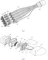
- Fig.3 is an illustrative perspective view of a fiber optic connection assembly for fiber to the home according to an exemplary embodiment of the present invention.
- the fiber optic connection assembly mainly comprises a multi-fiber optical cable 100, a plurality of single-fiber optical cables 200 and a fan-out member 300.
- the multi-fiber optical cable 100 has a first end introduced into the fan-out member 300 and a second end extending out of the fan-out member 300.
- a multi-fiber optic connector 110 is hermetically connected to the second end of the multi-fiber optical cable 100.
- the multi-fiber optic connector 110 may be coupled to another mating multi-fiber optic connector (not shown) by a fiber optic adapter.
- the plurality of single-fiber optical cables 200 each has a first end introduced into the fan-out member 300 and a second end extending out of the fan-out member 300.
- a plurality of single-fiber optic connectors 1000 are connected to the second ends of the single-fiber optical cables 200, respectively.
- the single-fiber optic connectors 1000 each may be coupled to another mating single-fiber optic connector (not shown) from a user side by a fiber optic adapter 2000.
- the multi-fiber optical cable 100 and the single-fiber optical cables 200 are introduced into the fan-out member 300 from the same side of the fan-out member 300.
- the present invention is not limited to this, in other embodiments, the multi-fiber optical cable 100 and the single-fiber optical cables 200 may be introduced into the fan-out member 300 from different sides of the fan-out member 300, as shown in Figs.6-7 and 9 .
- the single-fiber optical cables 200 have the same length extending out of the fan-out member 300. But the present invention is not limited to this, in other embodiments, the single-fiber optical cables 200 may have different lengths extending out of the fan-out member 300, as shown in Figs.8-9 .
- each group of single-fiber optical cables 200 has four single-fiber optical cables 200.
- the single-fiber optic connectors 1000 of the same one group of single-fiber optical cables 200 are arranged in the same layer; and the single-fiber optic connectors 1000 of different groups of single-fiber optical cables 200 are arranged in different layers and may be held in different layers by, for example, a locking mechanism.
- the present invention is not limited to the illustrated embodiments, the number and the arrangement of the single-fiber optical cables 200 may be freely adjusted as necessary.
- each group of single-fiber optical cables 200 have a same length extending out of the fan-out member 300; and different groups of single-fiber optical cables 200 also have the same length extending out of the fan-out member 300.
- the present invention is not limited to this, in other embodiments, the different groups of single-fiber optical cables 200 may have different lengths extending out of the fan-out member 300, as shown in Figs.8-9 .
- the single-fiber optic connector 1000 may be configured to be a sealed type of fiber optic connector to have excellent waterproof performance.
- the fiber optic connection assembly may further comprises a plurality of first fiber optic adapters 2000 mated with the plurality of single-fiber optic connectors 1000, respectively.
- the single-fiber optic connector 1000 may be coupled to another mating single-fiber optic connector (not shown) from a user side by the fiber optic adapter 2000.
- the fiber optic connection assembly may further comprises a second fiber optic adapter (not shown in Fig.3 ) mated with the multi-fiber optic connector 110.
- the multi-fiber optic connector 110 may be hermetically fitted in the second fiber optic adapter.
- Fig.4 is an illustrative exploded perspective view of a fan-out member 300 according to an exemplary embodiment of the present invention
- Fig.5 is a cross section view of the fan-out member 300 of Fig.4 after it has been assembled.
- any fiber optic connector and fiber optic adapter in the fan-out member 300 there is not provided any fiber optic connector and fiber optic adapter in the fan-out member 300.
- the fiber optic connector 110, 1000 and fiber optic adapters 2000 are all disposed on ends of the respective optical cables 100, 200 extending outside of the fan-out member 300.
- the single-fiber optic connectors of the fiber optic connection assembly and the mating single-fiber optic connector (not shown) from the user side are hermetically fitted in the first fiber optic adapters 2000.
- the respective port of the first fiber optic adapter 2000 may be provisionally sealed by a sealing cap 2200.
- the sealing cap 2200 may be simply removed, and the mating single-fiber optic connector of the user side can be inserted into the respective port of the first fiber optic adapter 2000. In this way, the fiber of the single-fiber optical cable 200 can be optically coupled to a mating fiber of the single-fiber optical cable of the user side.
- the multi-fiber optical cable 100 and the single-fiber optical cables 200 are hermetically fitted in the fan-out member 300.
- the sealing manners of the multi-fiber optical cable 100 and the single-fiber optical cables 200 in detail according to several embodiments.
- the multi-fiber optical cable 100 and the single-fiber optical cables 200 are hermetically fitted in the fan-out member 300 by pressing a sealing gel block 306.
- the fan-out member 300 mainly comprises a housing 301, a tray 302, 303, a first pressing plate 305, the sealing gel block 306, and a second pressing plate 307.
- the tray 302, 303 is received in the housing 301 to store and manage the fibers of the multi-fiber optical cable 100.
- the tray 302, 303 comprises a body 302 and cover 303 fitted or sealed on the body 302.
- the tray 302, 303 contains a pillar 310 inside thereof.
- the redundant fibers of the multi-fiber optical cable 100 may be wound on the pillar 310.
- the first pressing plate 305 may be hermetically fitted in the housing 301 by a sealing ring 304.
- the second pressing plate 307 is disposed at a side of the first pressing plate 305 opposite to the housing 301, and the sealing gel block 306 is received in an inner space defined by the first and second pressing plates 305, 307.
- the first end of the multi-fiber optical cable 100 extends into the housing 301after passing through the second pressing plate 307, the sealing gel block 306 and the first pressing plate 305.
- the first ends of fibers of the single-fiber optical cable 200 are received in holes 308 formed in the sealing gel block 306, respectively, after passing through holes formed in the second pressing plate 307.
- the housing 301, the sealing gel block 306 and the second pressing plate 307 may be assembled together by bolts.
- the sealing gel block 306 and the sealing ring 304 can be pressed by screwing the bolts, so that the multi-fiber optical cable 100 and the single-fiber optical cable 200 can be hermetically fitted in the fan-out member 300 (the fibers of the multi-fiber optical cable 100 and the single-fiber optical cable 200 can be hermetically sealed in the fan-out member 300).
- the multi-fiber optical cable 100 is fixed to the first pressing plate 305 with, for example, epoxy glue. As a result, an external force exerted on the multi-fiber optical cable 100 is transferred to the housing 301 rather than the fibers of the multi-fiber optical cable 100.
- a crimp ring 201 is crimped on the first end of the single-fiber optical cable 200, and the crimp ring 201 has a diameter larger than that of the hole in the second pressing plate 307 to prevent the single-fiber optical cable 200 from being disengaged from the second pressing plate 307, and transfer an external force exerted on the single-fiber optical cable 200 to the housing 301 rather than the fiber of the single-fiber optical cable 200.
- the fan-out member 300 may further comprises an elastic tail sleeve 309 sleeved on the multi-fiber optical cable 100 and the single-fiber optical cables 200 and connected to the second pressing plate 307 at an end of the housing 301 to protect the multi-fiber optical cable 100 and the single-fiber optical cables 200 from being damaged by a lateral force.
- Fig.6 is an illustrative exploded perspective view of a fan-out member according to another exemplary embodiment of the present invention.
- the multi-fiber optical cable 100 and the single-fiber optical cable 200 are hermetically fitted in the fan-out member 300 by filling a sealing gel into the fan-out member 300.
- the fan-out member mainly comprises a housing 301', 302' and an end plate 301'.
- the housing 301', 302' defined a chamber 311' therein.
- the end plate 307' is fitted in a port of the housing 301', 302'.
- the housing 301', 302' comprises a body 301' and a cover 302' fitted on the body 301'.
- the first end of the single-fiber optical cable 200 passes through a hole in the end plate 307' and extends into the chamber 311', and the first end of the multi-fiber optical cable 100 extends into the chamber 311' of the housing 301'.
- the sealing gel is filled into the chamber 311' of the housing 301', 302', the multi-fiber optical cable 100 and the single-fiber optical cables 200 are sealed in the fan-out member 300.
- the multi-fiber optical cable 100 may be fixed to the housing 301' to transfer an external force exerted on the multi-fiber optical cable 100 to the housing 301' rather than the fibers of the multi-fiber optical cable 100.
- a crimp ring 201 is crimped on the first end of the single-fiber optical cable 200, and the crimp ring 201 has a diameter larger than that of the hole in the end plate 307' to prevent the single-fiber optical cable 200 from being disengaged from the end plate 307' and transfer an external force exerted on the single-fiber optical cable 200 to the housing 301' rather than the fiber of the single-fiber optical cable 200.
- the fan-out member 300 may further comprises an elastic tail sleeve 309' sleeved on the single-fiber optical cables 200 and connected to the end plate 307' to protect the single-fiber optical cables 200 from being damaged by a lateral force.
- the fan-out member 300 may further comprises a tray 310' for store and managing the redundant fibers of the multi-fiber optical cable 100.
- the tray 310' is received in the chamber 311' of the housing 301'.
- Fig.7 is an illustrative exploded perspective view of a fan-out member according to yet another exemplary embodiment of the present invention.
- the fan-out member does not comprise a tray for managing the fibers of the multi-fiber optical cable 100, and Kevlar elements 101 of the multi-fiber optical cable 100 may be directly joined to the crimp ring 201 of the single-fiber optical cables 200 by a sealing gel.
- the fibers of the multi-fiber optical cable 100 can be directly spliced with the fibers of the single-fiber optical cables 200, respectively, without needing a tray to manage the fiber of the multi-fiber optical cable 100.
- Kevlar elements of the single-fiber optical cables 200 is disposed on a metal piece 202 and is crimped on the metal piece 202 by the crimp ring 201.
- the fan-out member is configured to have a cylindrical housing 301'.
- the cylindrical fan-out member defines a chamber 311' in the housing 301'.
- the sealing gel is filled into the chamber 311' of the housing 301', the multi-fiber optical cable 100 and the single-fiber optical cables 200 are sealed in the fan-out member 300.
- the single-fiber optical cables 200 are introduced into the fan-out member from one side of the fan-out member, and the multi-fiber optical cable 100 is introduced into the fan-out member from the other side of the fan-out member.
- An elastic tail sleeve 309' is sleeved on the multi-fiber optical cable 100 and connected to the housing 301' to protect the multi-fiber optical cable 100 from being damaged by a lateral force.
- another elastic tail sleeve 309' is sleeved on the single-fiber optical cables 200 and connected to the housing 301' to protect the single-fiber optical cables 200 from being damaged by a lateral force.
- the present invention is not limited to the illustrated embodiments. Many other suitable fan-out members may be made according to the teaching of the present invention.
- the plurality of single-fiber optical cables 200 each may have a fiber spliced with a respective one of the plurality of fibers of the multi-fiber optical cable 100 in the fan-out member 300.
- a splitter may be disposed in the fan-out member 300 to separate the multi-fiber optical cable 100 into a plurality of fibers, and the plurality of fibers of the multi-fiber optical cable 100 each may directly run through a respective one of the single-fiber optical cables 200 and is terminated at the single-fiber optic connector 1000 on the respective one of the single-fiber optical cables 200.
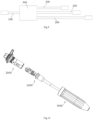
- Fig.10 is an illustrative exploded view of a fiber optic connection seal assembly for the fiber optic connection assembly of Fig.3 according to an exemplary embodiment of the present invention.
- the fiber optic connection seal assembly mainly comprises the fiber optic connector 1000, the fiber optic adapter 2000 and an outer shield 3000.
- Fig.11 is an illustrative assembled view of a fiber optic connection seal assembly according to an exemplary embodiment of the present invention
- Fig.13 is a cross section view of the fiber optic connection seal assembly of Fig.11 .
- an end of an optical cable 1000 is inserted into and coupled to the fiber optic connector 1000.
- the fiber optic adapter 2000 is configured to position the fiber optic connector 1000 therein, so that the fiber optic connector 1000 is optically coupled with a mating fiber optic connector (not shown) in the fiber optic adapter 2000 .
- the outer shield 3000 is disposed on the fiber optic connector 1000 and the fiber optic adapter 2000.
- the outer shield 3000 is hermetically fitted on the fiber optic connector 1000 and the fiber optic adapter 2000 to form a sealed inner chamber so as to prevent moisture or water from entering into the inner chamber.
- the fiber optic connector 1000 may comprise LC connector or other type of connector.
- the outer shield 3000 has a first end and a second end opposite to the first end.
- the first end of the outer shield 3000 is screwed onto a housing 2100 of the fiber optic adapter 2000.
- a first elastic seal ring 1010 is interposed between an inner flange surface 3020 (see Fig.14 ) of the first end of the outer shield 3000 and an outer flange surface (not indicated) of the housing 2100 of the fiber optic adapter 2000.
- the first elastic seal ring 1010 is axially pressed between the inner flange surface 3020 of the outer shield 3000 and the outer flange surface of the fiber optic adapter 2000 to seal an interface between the outer shield 3000 and the fiber optic adapter 2000.
- Fig. 12 is an illustrative perspective exploded view of the fiber optic connector 1000 of Fig. 10 .
- the fiber optic connector 1000 comprises an outer tube 1300 having a groove 1330 formed in an outer wall of the outer tube 1300.
- a second elastic seal ring 1020 is received in the groove 1330.
- the outer tube 1300 may be made of metal.
- the outer shield 3000 is formed with a radial protrusion 3300 on an inner wall of the outer shield 3000 at the second end of the outer shield 3000.
- the second elastic seal ring 1020 is radially inward pressed in the groove 1330 by the an inner peripheral surface 3030 of the radial protrusion 3300 to seal an interface between the outer shield 3000 and the fiber optic connector 1000.
- the fiber optic adapter 2000 comprises a seal cap 2200 screwed into a port of the housing 2100 of the fiber optic adapter 2000 opposite to the fiber optic connector 1000.
- a third elastic seal ring 1030 is interposed between an outer peripheral surface of the seal cap 2200 and an inner peripheral surface of the housing 2100 of the fiber optic adapter 2000.
- the third elastic seal ring 1030 is radially inward pressed between the outer peripheral surface of the seal cap 2200 and the inner peripheral surface of the fiber optic adapter 2000 to seal an interface between the seal cap 2200 and the fiber optic adapter 2000.
- the seal cap 2200 may be removed, and the mating fiber optic connector may be inserted into the port of the fiber optic adapter 2000. In this way, the fiber optic connector 1000 is coupled with the mating fiber optic connector.
- the fiber optic connector 1000 comprises a shrinkable tube 1600 having a first end 1610 firmly attached on a first end 1310 of the outer tube 1300 and a second end 1620 firmly attached on the optical cable 200 to seal an interface between the fiber optic connector 1000 and the optical cable 200.
- the radial protrusion 3300 of the outer shield 3000 has a slope 3100 for guiding the second elastic seal ring 1020 to the inner peripheral surface 3030 of the radial protrusion 3300.
- Fig.15 is an enlarged cross section view of the outer tube 1300 of Fig.12 ; and Fig.16 is an enlarged cross section view of an inner tube 1200 of Fig.12 .
- the fiber optic connector 1000 further comprises an inner tube 1200 passing through the outer tube 1300 and having a first end inserted into a housing 1100 of the fiber optic connector 1000.
- a buffer spring 1400 is provided between an outer flange 1220 on an outer wall of a second end of the inner tube 1200 and an inner flange 1340 (see Fig.15 ) on an inner wall of the second end of the outer tube 1300.
- a slot 1210 is formed in the outer wall of the inner tube 1200, and a block ring 1700 is received in the slot 1210.
- the outer tube 1300 is formed with an radial outer protrusion 1320 at the second end of the outer tube 1300, and the radial outer protrusion 1320 is limited between an radial inner protrusion 3300 of the outer shield 3000 and the block ring 1700 to prevent the outer tube 1300 and the buffer spring 1400 from being disengaged from the inner tube 1200.
- the inner tube 1200 may be made of metal.
- the radial outer protrusion 1320 of the outer tube 1300 has a first axial force carrying face 1350 (see Fig.15 ), and the radial protrusion 3300 of the outer shield 3000 has a second axial force carrying face 3320 (see Figs. 13-14 ) facing the first axial force carrying face 1350.
- the first axial force carrying face 1350 of the outer tube 1300 abuts against the second axial force carrying face 3320 of the outer shield 3000 to prevent the fiber optic connector 1000 from being pulled out of the outer shield 3000 and prevent the external force from being transferred to the inner tube 1200 and a ferrule (not indicated, which is received in the housing 1100) of the fiber optic connector 1000.
- the fiber optic connector 1000 may further comprise a crimp tube 1500 for crimping Kevlar elements of the optical cable 200 on the first end 1310 of the outer tube 1300 to prevent the external force exerted on the optical cable 200 from being transferred to the ferrule of the fiber optic connector.
- an outer surface of the first end 1310 of the outer tube 1300 is knurled to enhance a friction engagement force with the crimp tube 1500 and reliably hold the Kevlar elements of the optical cable 200 on the outer tube 1300.
- the outer shield 3000 provides a simple and reliable seal structure, and the fiber optic connection seal assembly may reach a classification of waterproof IP68. Furthermore, once the outer shield 3000 is screwed onto the fiber optic adapter 2000, the fiber optic connector 1000 is reliably positioned in the outer shield 3000 and cannot be pulled out of the outer shield 3000 under the external force, therefore, the seal performance of the assembly is independent of the external force exerted on the optical cable 200.
- the outer shield 3000 can limit a movement of the outer tube 1300 on which Kevlar elements of the optical cable 200 are crimped so as to prevent the external force exerted on the optical cable 200 from being transferred to the ferrule of the fiber optic connector 1000, therefore, the optical performance of the fiber optic connector 1000 is not affected by the external force.
Landscapes
- Physics & Mathematics (AREA)
- General Physics & Mathematics (AREA)
- Optics & Photonics (AREA)
- Mechanical Coupling Of Light Guides (AREA)
- Light Guides In General And Applications Therefor (AREA)
Description
- The present invention relates to a fiber optic connection assembly, more particularly, relates to a fiber optic connection assembly for fiber to the home (FTTH).
- In a conventional technology of fiber to the home (FTTH), a fiber optic connection box is commonly used to couple fibers of a multi-fiber optical cable to respective fibers of single-fiber optical cables of a user side. For example,
Fig. 1 is an illustrative perspective view of a conventional fiberoptic connection box 10, andFig.2 shows the fiberoptic connection box 10 ofFig. 1 after acover 14 is removed from abody 12. - As shown in
Figs. 1-2 , the fiber optic connection box mainly comprises thebody 12 and thecover 14. A multi-fiberoptical cable 16 containing a plurality of fibers is introduced into thebody 12 from an end of the fiberoptic connection box 10. A plurality of fiberoptic adapters 18 are provided on a back side of thebody 12. The fiberoptic adapters 18 each comprises an internal port located inside thebody 12 and an external port located outside thebody 12. When the fiberoptic adapter 18 is not in use, the external port is often sealed by a sealingcap 19. When it needs to operate the external port, the sealingcap 19 can be simply removed. - Referring to
Figs. 1-2 again, the plurality offibers 11 of the multi-fiberoptical cable 16 are coupled to a plurality of single-fiberoptic connectors 13, respectively. The single-fiberoptic connector 13 is fitted in the internal port of the fiberoptic adapter 18. When a single-fiber optic connector of the user side is fitted in the external port of the fiberoptic adapter 18 after the sealingcap 19 is removed from the external port, the single-fiberoptic connector 13 is coupled to the single-fiber optic connector of the user side, and the fiber of the multi-fiberoptical cable 16 is optically coupled to the fiber of the single-fiber optic connector of the user side. - Please refer to
Figs. 1-2 , the fiberoptic connectors 13 andadapters 18 are all provided in the fiberoptic connection box 10. Therefore, the conventional fiberoptic connection box 10 has a large size and cannot be used in a narrow workspace, for example, in a well. Accordingly, the conventional fiberoptic connection box 10 is limited in the practical application. Further, the cost of the conventional fiberoptic connection box 10 is very high. - Furthermore, as shown in
Figs. 1-2 , the fiberoptic adapters 18 are fixed on thebody 12 of the fiberoptic connection box 10, therefore, the single-fiber optical cable from the user side must have an enough length to be coupled to the fiberoptic connector 18. If the single-fiber optical cable from the user side is too short to reach the fiberoptic connector 18, the single-fiber optical cable from the user side must be replaced, complicating the operation of coupling fibers. -
US 2006/0133758 A1 discloses a fiber optic connection assembly comprising a fan-out member, a multi-fiber optical cable having a first end introduced into the fan-out member and a plurality of single-fiber optical cables each having a first end introduced into the fan-out member, wherein the multi-fiber optical cable and the single-fiber optical cables are introduced into the fan-out member from different sides of the fan-out member. - The present invention has been made to overcome or alleviate at least one aspect of the above mentioned disadvantages.
- Accordingly, it is an object of the present invention to provide a fiber optic connection assembly having a small volume and adapted to be used in a narrow workspace.
- According to an aspect of the present invention, there is provided a fiber optic connection assembly for fiber to the home, comprising: a fan-out member; a multi-fiber optical cable having a first end introduced into the fan-out member and a second end extending out of the fan-out member; a multi-fiber optic connector connected to the second end of the multi-fiber optical cable; a plurality of single-fiber optical cables each having a first end introduced into the fan-out member and a second end extending out of the fan-out member; and a plurality of single-fiber optic connectors connected to the second ends of the single-fiber optical cables, respectively; a plurality of first fiber optic adapters mated with the plurality of single-fiber optic connectors, respectively; and a plurality of outer shields each constructed to receive the connector and the adapter of a respective single-fiber optical cable therein, wherein the outer shield is hermetically fitted on the connector and the adapter of the respective single-fiber optical cable to form a sealed inner chamber so as to prevent moisture or water from entering into the inner chamber.
- The above and other features of the present invention will become more apparent by describing in detail exemplary embodiments thereof with reference to the accompanying drawings, in which:
-
Fig.1 is an illustrative perspective view of a conventional fiber optic connection box; -
Fig.2 shows the fiber optic connection box ofFig. 1 , wherein a cover has been removed from a body; -
Fig.3 is an illustrative perspective view of a fiber optic connection assembly for fiber to the home according to an exemplary embodiment of the present invention; -
Fig.4 is an illustrative exploded perspective view of a fan-out member according to an exemplary embodiment of the present invention; -
Fig.5 is a cross section view of the fan-out member ofFig.4 after it has been assembled; -
Fig.6 is an illustrative exploded perspective view of a fan-out member according to another exemplary embodiment of the present invention; -
Fig.7 is an illustrative exploded perspective view of a fan-out member according to yet another exemplary embodiment of the present invention; -
Fig.8 is an illustrative view of a fiber optic connection assembly according to another exemplary embodiment of the present invention; -
Fig.9 is an illustrative view of a fiber optic connection assembly according to yet another exemplary embodiment of the present invention; -
Fig.10 is an illustrative exploded view of a fiber optic connection seal assembly for the fiber optic connection assembly ofFig.3 according to an exemplary embodiment of the present invention; -
Fig.11 is an illustrative assembled view of a fiber optic connection seal assembly according to an exemplary embodiment of the present invention; -
Fig.12 is an illustrative perspective exploded view of a fiber optic connector ofFig.10 ; -
Fig. 13 is a cross section view of the fiber optic connection seal assembly ofFig.11 ; -
Fig.14 is an enlarged cross section view of an outer shield ofFig.10 ; -
Fig.15 is an enlarged cross section view of an outer tube ofFig.12 ; and -
Fig.16 is an enlarged cross section view of an inner tube ofFig.12 . - Exemplary embodiments of the present disclosure will be described hereinafter in detail with reference to the attached drawings, wherein the like reference numerals refer to the like elements. The present disclosure may, however, be embodied in many different forms and should not be construed as being limited to the embodiment set forth herein; rather, these embodiments are provided so that the present disclosure will be thorough and complete, and will fully convey the concept of the disclosure to those skilled in the art.
-
Fig.3 is an illustrative perspective view of a fiber optic connection assembly for fiber to the home according to an exemplary embodiment of the present invention. - As shown in
Fig.3 , the fiber optic connection assembly mainly comprises a multi-fiberoptical cable 100, a plurality of single-fiberoptical cables 200 and a fan-outmember 300. - Referring to
Fig.3 , the multi-fiberoptical cable 100 has a first end introduced into the fan-outmember 300 and a second end extending out of the fan-outmember 300. A multi-fiberoptic connector 110 is hermetically connected to the second end of the multi-fiberoptical cable 100. The multi-fiberoptic connector 110 may be coupled to another mating multi-fiber optic connector (not shown) by a fiber optic adapter. - Please refer to
Fig.3 again, the plurality of single-fiberoptical cables 200 each has a first end introduced into the fan-outmember 300 and a second end extending out of the fan-outmember 300. A plurality of single-fiberoptic connectors 1000 are connected to the second ends of the single-fiberoptical cables 200, respectively. The single-fiberoptic connectors 1000 each may be coupled to another mating single-fiber optic connector (not shown) from a user side by a fiberoptic adapter 2000. - In the illustrated embodiment of
Fig.3 , the multi-fiberoptical cable 100 and the single-fiberoptical cables 200 are introduced into the fan-outmember 300 from the same side of the fan-outmember 300. But the present invention is not limited to this, in other embodiments, the multi-fiberoptical cable 100 and the single-fiberoptical cables 200 may be introduced into the fan-outmember 300 from different sides of the fan-outmember 300, as shown inFigs.6-7 and9 . - Please refer to
Fig.3 again, in an exemplary embodiment, the single-fiberoptical cables 200 have the same length extending out of the fan-outmember 300. But the present invention is not limited to this, in other embodiments, the single-fiberoptical cables 200 may have different lengths extending out of the fan-outmember 300, as shown inFigs.8-9 . - In the illustrated embodiment of
Fig.3 , there are provided twelve single-fiberoptical cables 200. The twelve single-fiberoptical cables 200 are divided into three groups. Each group of single-fiberoptical cables 200 has four single-fiberoptical cables 200. As shown inFig.3 , the single-fiberoptic connectors 1000 of the same one group of single-fiberoptical cables 200 are arranged in the same layer; and the single-fiberoptic connectors 1000 of different groups of single-fiberoptical cables 200 are arranged in different layers and may be held in different layers by, for example, a locking mechanism. - Please be noted that the present invention is not limited to the illustrated embodiments, the number and the arrangement of the single-fiber
optical cables 200 may be freely adjusted as necessary. - As shown in
Fig.3 , each group of single-fiberoptical cables 200 have a same length extending out of the fan-outmember 300; and different groups of single-fiberoptical cables 200 also have the same length extending out of the fan-outmember 300. But the present invention is not limited to this, in other embodiments, the different groups of single-fiberoptical cables 200 may have different lengths extending out of the fan-outmember 300, as shown inFigs.8-9 . - Referring to
Fig.3 , in an exemplary embodiment of the present invention, the single-fiber optic connector 1000 may be configured to be a sealed type of fiber optic connector to have excellent waterproof performance. - In an exemplary embodiment of the present invention, as shown in
Fig.3 , the fiber optic connection assembly may further comprises a plurality of firstfiber optic adapters 2000 mated with the plurality of single-fiber optic connectors 1000, respectively. The single-fiber optic connector 1000 may be coupled to another mating single-fiber optic connector (not shown) from a user side by thefiber optic adapter 2000. - In an exemplary embodiment of the present invention, as shown in
Fig.3 , the fiber optic connection assembly may further comprises a second fiber optic adapter (not shown inFig.3 ) mated with the multi-fiberoptic connector 110. The multi-fiberoptic connector 110 may be hermetically fitted in the second fiber optic adapter. -
Fig.4 is an illustrative exploded perspective view of a fan-outmember 300 according to an exemplary embodiment of the present invention;Fig.5 is a cross section view of the fan-outmember 300 ofFig.4 after it has been assembled. - As shown in
Figs.3-5 , there is not provided any fiber optic connector and fiber optic adapter in the fan-outmember 300. Thefiber optic connector fiber optic adapters 2000 are all disposed on ends of the respectiveoptical cables member 300. - In an exemplary embodiment of the present invention, the single-fiber optic connectors of the fiber optic connection assembly and the mating single-fiber optic connector (not shown) from the user side are hermetically fitted in the first
fiber optic adapters 2000. - As shown in
Fig.3 , before the mating single-fiber optic connector of the user side is fitted into a respective port of the firstfiber optic adapter 2000, the respective port of the firstfiber optic adapter 2000 may be provisionally sealed by asealing cap 2200. When it needs to fit the mating single-fiber optic connector of the user side into the respective port of the firstfiber optic adapter 2000, thesealing cap 2200 may be simply removed, and the mating single-fiber optic connector of the user side can be inserted into the respective port of the firstfiber optic adapter 2000. In this way, the fiber of the single-fiberoptical cable 200 can be optically coupled to a mating fiber of the single-fiber optical cable of the user side. - In the illustrated embodiments, the multi-fiber
optical cable 100 and the single-fiberoptical cables 200 are hermetically fitted in the fan-outmember 300. Hereafter, it will describe the sealing manners of the multi-fiberoptical cable 100 and the single-fiberoptical cables 200 in detail according to several embodiments. - As shown in
Figs.4-5 , the multi-fiberoptical cable 100 and the single-fiberoptical cables 200 are hermetically fitted in the fan-outmember 300 by pressing a sealinggel block 306. - In the illustrated embodiment of
Figs.4-5 , the fan-outmember 300 mainly comprises ahousing 301, atray pressing plate 305, the sealinggel block 306, and a secondpressing plate 307. - As shown in
Figs.4-5 , thetray housing 301 to store and manage the fibers of the multi-fiberoptical cable 100. Thetray body 302 and cover 303 fitted or sealed on thebody 302. In addition thetray pillar 310 inside thereof. The redundant fibers of the multi-fiberoptical cable 100 may be wound on thepillar 310. - As shown in
Figs.4-5 , the firstpressing plate 305 may be hermetically fitted in thehousing 301 by a sealingring 304. - As shown in
Figs.4-5 , the secondpressing plate 307 is disposed at a side of the firstpressing plate 305 opposite to thehousing 301, and the sealinggel block 306 is received in an inner space defined by the first and secondpressing plates - Please refer to
Figs.4-5 again, the first end of the multi-fiberoptical cable 100 extends into the housing 301after passing through the secondpressing plate 307, the sealinggel block 306 and the firstpressing plate 305. The first ends of fibers of the single-fiberoptical cable 200 are received inholes 308 formed in the sealinggel block 306, respectively, after passing through holes formed in the secondpressing plate 307. - In the illustrated embodiment of
Figs.4-5 , thehousing 301, the sealinggel block 306 and the secondpressing plate 307 may be assembled together by bolts. In this case, the sealinggel block 306 and thesealing ring 304 can be pressed by screwing the bolts, so that the multi-fiberoptical cable 100 and the single-fiberoptical cable 200 can be hermetically fitted in the fan-out member 300 (the fibers of the multi-fiberoptical cable 100 and the single-fiberoptical cable 200 can be hermetically sealed in the fan-out member 300). - Referring to
Figs.4-5 , the multi-fiberoptical cable 100 is fixed to the firstpressing plate 305 with, for example, epoxy glue. As a result, an external force exerted on the multi-fiberoptical cable 100 is transferred to thehousing 301 rather than the fibers of the multi-fiberoptical cable 100. - Referring to
Figs.4-5 , acrimp ring 201 is crimped on the first end of the single-fiberoptical cable 200, and thecrimp ring 201 has a diameter larger than that of the hole in the secondpressing plate 307 to prevent the single-fiberoptical cable 200 from being disengaged from the secondpressing plate 307, and transfer an external force exerted on the single-fiberoptical cable 200 to thehousing 301 rather than the fiber of the single-fiberoptical cable 200. - As shown in
Figs.4-5 , the fan-outmember 300 may further comprises anelastic tail sleeve 309 sleeved on the multi-fiberoptical cable 100 and the single-fiberoptical cables 200 and connected to the secondpressing plate 307 at an end of thehousing 301 to protect the multi-fiberoptical cable 100 and the single-fiberoptical cables 200 from being damaged by a lateral force. -
Fig.6 is an illustrative exploded perspective view of a fan-out member according to another exemplary embodiment of the present invention. - As shown in
Fig.6 , the multi-fiberoptical cable 100 and the single-fiberoptical cable 200 are hermetically fitted in the fan-outmember 300 by filling a sealing gel into the fan-outmember 300. - Referring to
Fig.6 , the fan-out member mainly comprises a housing 301', 302' and an end plate 301'. The housing 301', 302' defined a chamber 311' therein. The end plate 307' is fitted in a port of the housing 301', 302'. The housing 301', 302' comprises a body 301' and a cover 302' fitted on the body 301'. - Please refer to
Fig.6 , the first end of the single-fiberoptical cable 200 passes through a hole in the end plate 307' and extends into the chamber 311', and the first end of the multi-fiberoptical cable 100 extends into the chamber 311' of the housing 301'. When the sealing gel is filled into the chamber 311' of the housing 301', 302', the multi-fiberoptical cable 100 and the single-fiberoptical cables 200 are sealed in the fan-outmember 300. - As shown in
Fig.6 , the multi-fiberoptical cable 100 may be fixed to the housing 301' to transfer an external force exerted on the multi-fiberoptical cable 100 to the housing 301' rather than the fibers of the multi-fiberoptical cable 100. - Referring to
Fig.6 again, acrimp ring 201 is crimped on the first end of the single-fiberoptical cable 200, and thecrimp ring 201 has a diameter larger than that of the hole in the end plate 307' to prevent the single-fiberoptical cable 200 from being disengaged from the end plate 307' and transfer an external force exerted on the single-fiberoptical cable 200 to the housing 301' rather than the fiber of the single-fiberoptical cable 200. - Please refer to
Fig.6 , the fan-outmember 300 may further comprises an elastic tail sleeve 309' sleeved on the single-fiberoptical cables 200 and connected to the end plate 307' to protect the single-fiberoptical cables 200 from being damaged by a lateral force. - As shown in
Fig.6 , the fan-outmember 300 may further comprises a tray 310' for store and managing the redundant fibers of the multi-fiberoptical cable 100. The tray 310' is received in the chamber 311' of the housing 301'. -
Fig.7 is an illustrative exploded perspective view of a fan-out member according to yet another exemplary embodiment of the present invention. - As shown in
Fig.7 , the fan-out member does not comprise a tray for managing the fibers of the multi-fiberoptical cable 100, andKevlar elements 101 of the multi-fiberoptical cable 100 may be directly joined to thecrimp ring 201 of the single-fiberoptical cables 200 by a sealing gel. In this case, the fibers of the multi-fiberoptical cable 100 can be directly spliced with the fibers of the single-fiberoptical cables 200, respectively, without needing a tray to manage the fiber of the multi-fiberoptical cable 100. - Referring to
Fig.7 , Kevlar elements of the single-fiberoptical cables 200 is disposed on ametal piece 202 and is crimped on themetal piece 202 by thecrimp ring 201. - In the illustrated embodiment of
Fig.7 , the fan-out member is configured to have a cylindrical housing 301'. The cylindrical fan-out member defines a chamber 311' in the housing 301'. When the sealing gel is filled into the chamber 311' of the housing 301', the multi-fiberoptical cable 100 and the single-fiberoptical cables 200 are sealed in the fan-outmember 300. - As shown in
Fig.7 , the single-fiberoptical cables 200 are introduced into the fan-out member from one side of the fan-out member, and the multi-fiberoptical cable 100 is introduced into the fan-out member from the other side of the fan-out member. An elastic tail sleeve 309' is sleeved on the multi-fiberoptical cable 100 and connected to the housing 301' to protect the multi-fiberoptical cable 100 from being damaged by a lateral force. Similarly, another elastic tail sleeve 309' is sleeved on the single-fiberoptical cables 200 and connected to the housing 301' to protect the single-fiberoptical cables 200 from being damaged by a lateral force. - Although several exemplary embodiments of the fan-out member have been shown and described with reference to
Figs.4-7 , the present invention is not limited to the illustrated embodiments. Many other suitable fan-out members may be made according to the teaching of the present invention. In an exemplary embodiment, the plurality of single-fiberoptical cables 200 each may have a fiber spliced with a respective one of the plurality of fibers of the multi-fiberoptical cable 100 in the fan-outmember 300. In another exemplary embodiment, a splitter may be disposed in the fan-outmember 300 to separate the multi-fiberoptical cable 100 into a plurality of fibers, and the plurality of fibers of the multi-fiberoptical cable 100 each may directly run through a respective one of the single-fiberoptical cables 200 and is terminated at the single-fiber optic connector 1000 on the respective one of the single-fiberoptical cables 200. - Hereafter, it will describe in detail a seal configuration for sealing the single-
fiber optic connector 1000 and theadapter 2000 of each single-fiberoptical cable 200 with reference toFigs.10-16 . -
Fig.10 is an illustrative exploded view of a fiber optic connection seal assembly for the fiber optic connection assembly ofFig.3 according to an exemplary embodiment of the present invention. - As shown in
Fig.10 , the fiber optic connection seal assembly mainly comprises thefiber optic connector 1000, thefiber optic adapter 2000 and anouter shield 3000. -
Fig.11 is an illustrative assembled view of a fiber optic connection seal assembly according to an exemplary embodiment of the present invention;Fig.13 is a cross section view of the fiber optic connection seal assembly ofFig.11 . - As shown in
Figs. 10-11 and13 , an end of anoptical cable 1000 is inserted into and coupled to thefiber optic connector 1000. Thefiber optic adapter 2000 is configured to position thefiber optic connector 1000 therein, so that thefiber optic connector 1000 is optically coupled with a mating fiber optic connector (not shown) in thefiber optic adapter 2000 . Theouter shield 3000 is disposed on thefiber optic connector 1000 and thefiber optic adapter 2000. Theouter shield 3000 is hermetically fitted on thefiber optic connector 1000 and thefiber optic adapter 2000 to form a sealed inner chamber so as to prevent moisture or water from entering into the inner chamber. - In an exemplary embodiment, the
fiber optic connector 1000 may comprise LC connector or other type of connector. - Please refer to
Fig.13 , theouter shield 3000 has a first end and a second end opposite to the first end. The first end of theouter shield 3000 is screwed onto ahousing 2100 of thefiber optic adapter 2000. A firstelastic seal ring 1010 is interposed between an inner flange surface 3020 (seeFig.14 ) of the first end of theouter shield 3000 and an outer flange surface (not indicated) of thehousing 2100 of thefiber optic adapter 2000. When theouter shield 3000 is screwed onto thehousing 2100 offiber optic adapter 2000, the firstelastic seal ring 1010 is axially pressed between theinner flange surface 3020 of theouter shield 3000 and the outer flange surface of thefiber optic adapter 2000 to seal an interface between theouter shield 3000 and thefiber optic adapter 2000. - In the illustrated embodiment of
Fig. 13 , when theouter shield 3000 is screwed in position on thefiber optic adapter 2000, for example, an end face of the first end of theouter shield 3000 becomes contact with thehousing 2100 of theadapter 2000, the interface between theouter shield 3000 and thefiber optic adapter 2000 is sealed by the firstelastic seal ring 1010. -
Fig. 12 is an illustrative perspective exploded view of thefiber optic connector 1000 ofFig. 10 . - As shown in
Fig. 12 , thefiber optic connector 1000 comprises anouter tube 1300 having agroove 1330 formed in an outer wall of theouter tube 1300. A secondelastic seal ring 1020 is received in thegroove 1330. Theouter tube 1300 may be made of metal. - As shown in
Figs. 13-14 , theouter shield 3000 is formed with aradial protrusion 3300 on an inner wall of theouter shield 3000 at the second end of theouter shield 3000. When theouter shield 3000 is screwed onto thehousing 2100 offiber optic adapter 2000, the secondelastic seal ring 1020 is radially inward pressed in thegroove 1330 by the an innerperipheral surface 3030 of theradial protrusion 3300 to seal an interface between theouter shield 3000 and thefiber optic connector 1000. - Referring to
Fig. 13 again, thefiber optic adapter 2000 comprises aseal cap 2200 screwed into a port of thehousing 2100 of thefiber optic adapter 2000 opposite to thefiber optic connector 1000. A thirdelastic seal ring 1030 is interposed between an outer peripheral surface of theseal cap 2200 and an inner peripheral surface of thehousing 2100 of thefiber optic adapter 2000. When theseal cap 2200 is screwed into the port offiber optic adapter 2000, the thirdelastic seal ring 1030 is radially inward pressed between the outer peripheral surface of theseal cap 2200 and the inner peripheral surface of thefiber optic adapter 2000 to seal an interface between theseal cap 2200 and thefiber optic adapter 2000. - In an exemplary embodiment of the present invention, when it needs to couple the
fiber optic connector 1000 with a mating fiber optic connector (not shown), theseal cap 2200 may be removed, and the mating fiber optic connector may be inserted into the port of thefiber optic adapter 2000. In this way, thefiber optic connector 1000 is coupled with the mating fiber optic connector. - As shown in
Figs.12-13 , thefiber optic connector 1000 comprises ashrinkable tube 1600 having afirst end 1610 firmly attached on afirst end 1310 of theouter tube 1300 and asecond end 1620 firmly attached on theoptical cable 200 to seal an interface between thefiber optic connector 1000 and theoptical cable 200. - As shown in
Figs. 13-14 , theradial protrusion 3300 of theouter shield 3000 has aslope 3100 for guiding the secondelastic seal ring 1020 to the innerperipheral surface 3030 of theradial protrusion 3300. -
Fig.15 is an enlarged cross section view of theouter tube 1300 ofFig.12 ; andFig.16 is an enlarged cross section view of aninner tube 1200 ofFig.12 . - As shown in
Figs. 12-13 and15-16 , thefiber optic connector 1000 further comprises aninner tube 1200 passing through theouter tube 1300 and having a first end inserted into ahousing 1100 of thefiber optic connector 1000. Abuffer spring 1400 is provided between anouter flange 1220 on an outer wall of a second end of theinner tube 1200 and an inner flange 1340 (seeFig.15 ) on an inner wall of the second end of theouter tube 1300. - As shown in
Figs. 12-13 and15-16 , aslot 1210 is formed in the outer wall of theinner tube 1200, and ablock ring 1700 is received in theslot 1210. Theouter tube 1300 is formed with an radialouter protrusion 1320 at the second end of theouter tube 1300, and the radialouter protrusion 1320 is limited between an radialinner protrusion 3300 of theouter shield 3000 and theblock ring 1700 to prevent theouter tube 1300 and thebuffer spring 1400 from being disengaged from theinner tube 1200. - In an exemplary embodiment of the present invention, the
inner tube 1200 may be made of metal. - As shown in
Figs. 13-15 , the radialouter protrusion 1320 of theouter tube 1300 has a first axial force carrying face 1350 (seeFig.15 ), and theradial protrusion 3300 of theouter shield 3000 has a second axial force carrying face 3320 (seeFigs. 13-14 ) facing the first axialforce carrying face 1350. As shown inFig.13 , when theoptical cable 200 is pulled outward by an external force, the first axialforce carrying face 1350 of theouter tube 1300 abuts against the second axialforce carrying face 3320 of theouter shield 3000 to prevent thefiber optic connector 1000 from being pulled out of theouter shield 3000 and prevent the external force from being transferred to theinner tube 1200 and a ferrule (not indicated, which is received in the housing 1100) of thefiber optic connector 1000. - As shown in
Figs. 12-13 , thefiber optic connector 1000 may further comprise acrimp tube 1500 for crimping Kevlar elements of theoptical cable 200 on thefirst end 1310 of theouter tube 1300 to prevent the external force exerted on theoptical cable 200 from being transferred to the ferrule of the fiber optic connector. - In an exemplary embodiment of the present invention, an outer surface of the
first end 1310 of theouter tube 1300 is knurled to enhance a friction engagement force with thecrimp tube 1500 and reliably hold the Kevlar elements of theoptical cable 200 on theouter tube 1300. - In the above various embodiments of the present invention, the
outer shield 3000 provides a simple and reliable seal structure, and the fiber optic connection seal assembly may reach a classification of waterproof IP68. Furthermore, once theouter shield 3000 is screwed onto thefiber optic adapter 2000, thefiber optic connector 1000 is reliably positioned in theouter shield 3000 and cannot be pulled out of theouter shield 3000 under the external force, therefore, the seal performance of the assembly is independent of the external force exerted on theoptical cable 200. Moreover, theouter shield 3000 can limit a movement of theouter tube 1300 on which Kevlar elements of theoptical cable 200 are crimped so as to prevent the external force exerted on theoptical cable 200 from being transferred to the ferrule of thefiber optic connector 1000, therefore, the optical performance of thefiber optic connector 1000 is not affected by the external force. - It should be appreciated for those skilled in this art that the above embodiments are intended to be illustrated, and not restrictive. For example, many modifications may be made to the above embodiments by those skilled in this art, and various features described in different embodiments may be freely combined with each other without conflicting in configuration or principle, so that more kinds of fiber optic connection assembly can be achieved with overcoming the technical problem of the present invention.
- Although several exemplary embodiments have been shown and described, it would be appreciated by those skilled in the art that various changes or modifications may be made in these embodiments without departing from the principles of the disclosure, the scope of which is defined in the claims.
- As used herein, an element recited in the singular and proceeded with the word "a" or "an" should be understood as not excluding plural of said elements or steps, unless such exclusion is explicitly stated. Furthermore, references to "one embodiment" of the present invention are not intended to be interpreted as excluding the existence of additional embodiments that also incorporate the recited features. Moreover, unless explicitly stated to the contrary, embodiments "comprising" or "having" an element or a plurality of elements having a particular property may include additional such elements not having that property.
Claims (15)
- A fiber optic connection assembly for fiber to the home, comprising:a fan-out member (300);a multi-fiber optical cable (100) having a first end introduced into the fan-out member (300) and a second end extending out of the fan-out member (300);a multi-fiber optic connector (110) connected to the second end of the multi-fiber optical cable (100);a plurality of single-fiber optical cables (200) each having a first end introduced into the fan-out member (300) and a second end extending out of the fan-out member (300), wherein the multi-fiber optical cable (100) and the single-fiber optical cables (200) are introduced into the fan-out member (300) from a same side of the fan-out member (300), the multi-fiber optical cable (100) and the single-fiber optical cables (200) are hermetically fitted in the fan-out member (300) by pressing a sealing gel block (306);a plurality of single-fiber optic connectors (1000) connected to the second ends of the single-fiber optical cables (200), respectively;a plurality of first fiber optic adapters (2000) mated with the plurality of single-fiber optic connectors (1000), respectively; anda plurality of outer shields (3000) each constructed to receive the connector (1000) and the adapter (2000) of a respective single-fiber optical cable (200) therein,wherein the outer shield (3000) is hermetically fitted on the connector (1000) and the adapter (2000) of the respective single-fiber optical cable (200) to form a sealed inner chamber so as to prevent moisture or water from entering into the inner chamber.
- The fiber optic connection assembly according to claim 1,wherein the outer shield (3000) has a first end screwed onto a housing (2100) of the fiber optic adapter (2000);wherein a first elastic seal ring (1010) is interposed between an inner flange surface (3020) of the first end of the outer shield (3000) and an outer flange surface of the housing (2100) of the fiber optic adapter (2000); andwhen the outer shield (3000) is screwed onto the housing (2100) of fiber optic adapter (2000), the first elastic seal ring (1010) is axially pressed between the inner flange surface (3020) of the outer shield (3000) and the outer flange surface of the fiber optic adapter (2000) to seal an interface between the outer shield (3000) and the fiber optic adapter (2000).
- The fiber optic connection assembly according to claim 1 or 2,wherein the fiber optic connector comprises an outer tube (1300) having a groove (1330) formed in an outer wall of the outer tube (1300), and a second elastic seal ring (1020) is received in the groove (1330);wherein the outer shield (3000) is formed with a radial protrusion (3300) on an inner wall of the outer shield (3000) at a second end of the outer shield (3000); andwhen the outer shield (3000) is screwed onto the housing (2100) of fiber optic adapter (2000), the second elastic seal ring (1020) is radially pressed in the groove (1330) by an inner peripheral surface (3030) of the radial protrusion (3300) to seal an interface between the outer shield (3000) and the fiber optic connector (1000).
- The fiber optic connection assembly according to claim 3,wherein the fiber optic adapter (2000) comprises a seal cap (2200) screwed into a port of the housing (2100) of the fiber optic adapter (2000) opposite to the fiber optic connector (1000);wherein a third elastic seal ring (1030) is interposed between an outer peripheral surface of the seal cap (2200) and an inner peripheral surface of the housing (2100) of the fiber optic adapter (2000); andwhen the seal cap (2200) is screwed into the port of the fiber optic adapter (2000), the third elastic seal ring (1030) is radially pressed between the outer peripheral surface of the seal cap (2200) and the inner peripheral surface of the fiber optic adapter (2000) to seal an interface between the seal cap (2200) and the fiber optic adapter (2000).
- The fiber optic connection assembly according to claim 4,
wherein the fiber optic connector (1000) comprises a shrinkable tube (1600) having a first end (1610) firmly attached on a first end of the outer tube (1300) and a second end (1620) firmly attached on the optical cable (200) to seal an interface between the fiber optic connector (1000) and the optical cable (200). - The fiber optic connection assembly according to claim 5,
wherein the radial protrusion (3300) of the outer shield (3000) has a slope (3100) for guiding the second elastic seal ring (1020) to the inner peripheral surface (3030) of the radial protrusion (3300). - The fiber optic connection assembly according to claim 6,wherein the fiber optic connector (1000) further comprises an inner tube (1200) passing through the outer tube (1300) and having a first end inserted into a housing (1100) of the fiber optic connector (1000); andwherein a buffer spring (1400) is interposed between an outer flange (1220) on an outer wall of a second end of the inner tube (1200) and an inner flange (1340) on an inner wall of the second end of the outer tube (1300).
- The fiber optic connection assembly according to claim 7,wherein a slot (1210) is formed in the outer wall of the inner tube (1200), and a block ring (1700) is received in the slot (1210); andwherein the outer tube (1300) is formed with a radial outer protrusion (1320) at the second end of the outer tube (1300), and the radial outer protrusion (1320) is limited between a radial inner protrusion (3300) of the outer shield (3000) and the block ring (1700) to prevent the outer tube (1300) and the buffer spring (1400) from being disengaged from the inner tube (1200).
- The fiber optic connection assembly according to claim 8,
wherein the fiber optic connector (1000) further comprises a crimp tube (1500) for crimping Kevlar elements of the optical cable (200) on the first end (1310) of the outer tube (1300) to prevent an external force exerted on the optical cable (200) from being transferred to a ferrule of the fiber optic connector, wherein an outer surface of the first end (1310) of the outer tube (1300) is knurled to enhance a friction engagement force with the crimp tube (1500). - The fiber optic connection assembly according to claim 1,wherein the single-fiber optical cables (200) have different lengths extending out the fan-out member (300);wherein the single-fiber optical cables (200) are divided into a plurality of groups, and each group of single-fiber optical cables (200) have a same length extending out the fan-out member (300); andwherein different groups of single-fiber optical cables (200) have a same length or different lengths extending out the fan-out member (300);wherein the single-fiber optic connectors (1000) of the same one group of single-fiber optical cables (200) are arranged in a same layer; andwherein the single-fiber optic connectors (1000) of different groups of single-fiber optical cables (200) are arranged in different layers.
- The fiber optic connection assembly according to claim 1,
wherein the single-fiber optic connector (1000) is configured to be a sealed type of optic connector. - The fiber optic connection assembly according to claim 1,
wherein the multi-fiber optical cable (100) and the single-fiber optical cables (200) are hermetically fitted in the fan-out member (300). - The fiber optic connection assembly according to claim 1,
wherein the plurality of single-fiber optical cables (200) each has a fiber spliced with a respective one of the plurality of fibers of the multi-fiber optical cable (100) in the fan-out member (300). - The fiber optic connection assembly according to claim 1,
wherein a splitter is disposed in the fan-out member (300) to separate the multi-fiber optical cable (100) into a plurality of fibers. - The fiber optic connection assembly according to claim 14,
wherein the plurality of fibers of the multi-fiber optical cable (100) each runs through a respective one of the single-fiber optical cables (200) and is terminated at the single-fiber optic connector (1000) on the respective one of the single-fiber optical cables (200).
Applications Claiming Priority (3)
| Application Number | Priority Date | Filing Date | Title |
|---|---|---|---|
| CN201310117198.7A CN104101953B (en) | 2013-04-07 | 2013-04-07 | Fiber optic connection components for fiber to the home |
| CN201320169165.2U CN203164475U (en) | 2013-04-07 | 2013-04-07 | Cable connector sealing assembly |
| PCT/IB2014/060209 WO2014167447A1 (en) | 2013-04-07 | 2014-03-27 | Fiber optic connection assembly |
Publications (2)
| Publication Number | Publication Date |
|---|---|
| EP2984513A1 EP2984513A1 (en) | 2016-02-17 |
| EP2984513B1 true EP2984513B1 (en) | 2023-02-15 |
Family
ID=50543270
Family Applications (1)
| Application Number | Title | Priority Date | Filing Date |
|---|---|---|---|
| EP14718760.3A Active EP2984513B1 (en) | 2013-04-07 | 2014-03-27 | Fiber optic connection assembly |
Country Status (5)
| Country | Link |
|---|---|
| US (3) | US20160041356A1 (en) |
| EP (1) | EP2984513B1 (en) |
| AU (4) | AU2014252282A1 (en) |
| ES (1) | ES1148183Y (en) |
| WO (1) | WO2014167447A1 (en) |
Families Citing this family (74)
| Publication number | Priority date | Publication date | Assignee | Title |
|---|---|---|---|---|
| WO2014167447A1 (en) * | 2013-04-07 | 2014-10-16 | Tyco Electronics (Shanghai) Co. Ltd. | Fiber optic connection assembly |
| WO2014197894A1 (en) * | 2013-06-07 | 2014-12-11 | Adc Telecommunications, Inc. | Telecommunications connection device |
| WO2015031342A1 (en) | 2013-08-26 | 2015-03-05 | Adc Telecommunications, Inc. | Wave division multiplexer arrangement for small cell networks |
| US10481341B2 (en) | 2014-08-14 | 2019-11-19 | CommScope Connectivity Belgium BVBA | Fiber optic adapter assembly |
| WO2016146848A2 (en) | 2015-03-19 | 2016-09-22 | Commscope Connectivity Uk Limited | Thermally conductive closure for electronics |
| EP3098633A1 (en) | 2015-05-29 | 2016-11-30 | Corning Optical Communications LLC | Cap apparatuses for sealing optical fiber connectors and associated methods |
| EP3098634A1 (en) | 2015-05-29 | 2016-11-30 | Corning Optical Communications LLC | Cap apparatuses for sealing optical fiber connectors and associated methods |
| US9835816B2 (en) | 2015-06-10 | 2017-12-05 | Telect, Inc. | Fiber blocking kits |
| EP3316013A4 (en) | 2015-06-23 | 2019-02-27 | ADC Telecommunications (Shanghai) Distribution Co., Ltd. | FIBER OPTIC CONNECTOR ASSEMBLY |
| US10151897B2 (en) | 2016-01-26 | 2018-12-11 | Commscope Technologies Llc | Fiber indexing systems |
| CN107193091B (en) | 2016-03-14 | 2020-09-04 | 康普科技有限责任公司 | Reinforced Female Fiber Optic Connector Cable Assemblies |
| US11092765B2 (en) | 2016-05-23 | 2021-08-17 | CommScope Connectivity Belgium BVBA | Optical termination enclosure with ruggedized self-supporting tethers |
| EP3465309A1 (en) | 2016-05-26 | 2019-04-10 | Corning Optical Communications LLC | Fiber optic multiport having different types of ports for multi-use |
| US9864156B1 (en) * | 2016-07-01 | 2018-01-09 | 3M Innovative Properties Company | Multi-purpose sealing device |
| US11073670B2 (en) | 2016-08-12 | 2021-07-27 | Corning Optical Communications LLC | Device and method for sealing multiport splitters |
| US10790899B2 (en) | 2017-01-12 | 2020-09-29 | Commscope Technologies Llc | Optical tapping in an indexing architecture |
| WO2018197410A1 (en) | 2017-04-25 | 2018-11-01 | CommScope Connectivity Belgium BVBA | Connection module for cable seal gel block |
| WO2018231833A1 (en) | 2017-06-12 | 2018-12-20 | Commscope Technologies Llc | Distributed tap architecture incorporating hardened connectivity |
| US12571977B2 (en) | 2017-06-28 | 2026-03-10 | Corning Research & Development Corporation | Multiports and other devices having optical connection ports with securing features and methods of making the same |
| US10359577B2 (en) | 2017-06-28 | 2019-07-23 | Corning Research & Development Corporation | Multiports and optical connectors with rotationally discrete locking and keying features |
| US11187859B2 (en) | 2017-06-28 | 2021-11-30 | Corning Research & Development Corporation | Fiber optic connectors and methods of making the same |
| CN111065946B (en) | 2017-06-28 | 2023-08-18 | 康宁研究与开发公司 | Multiport and other devices having keyed connection ports and securing features and methods of manufacture |
| US11300746B2 (en) | 2017-06-28 | 2022-04-12 | Corning Research & Development Corporation | Fiber optic port module inserts, assemblies and methods of making the same |
| US12271040B2 (en) | 2017-06-28 | 2025-04-08 | Corning Research & Development Corporation | Fiber optic extender ports, assemblies and methods of making the same |
| US11668890B2 (en) | 2017-06-28 | 2023-06-06 | Corning Research & Development Corporation | Multiports and other devices having optical connection ports with securing features and methods of making the same |
| MX2020000904A (en) | 2017-07-25 | 2020-07-22 | Commscope Technologies Llc | HARDENED EXIT FAN FIX. |
| USD941296S1 (en) | 2017-10-03 | 2022-01-18 | Corning Research & Development Corporation | Multiport for making optical connections |
| USD878370S1 (en) | 2017-10-03 | 2020-03-17 | Corning Research & Development Corporation | Multiports for making optical connections |
| USD941295S1 (en) | 2017-10-03 | 2022-01-18 | Corning Research & Development Corporation | Multiport for making optical connections |
| USD837788S1 (en) | 2017-11-30 | 2019-01-08 | Corning Research & Development Corporation | Multiport for making optical connections |
| USD878372S1 (en) | 2017-10-03 | 2020-03-17 | Corning Research & Development Corporation | Multiports for making optical connections |
| USD881132S1 (en) | 2017-11-30 | 2020-04-14 | Corning Research & Development Corporation | Multiport for making optical connections |
| USD941821S1 (en) | 2017-10-03 | 2022-01-25 | Corning Research & Development Corporation | Multiport for making optical connections |
| USD837216S1 (en) | 2017-11-30 | 2019-01-01 | Corning Research & Development Corporation | Multiport for making optical connections |
| USD837789S1 (en) | 2017-11-30 | 2019-01-08 | Corning Research & Development Corporation | Double-stack multiports for making optical connections |
| USD951954S1 (en) | 2018-03-29 | 2022-05-17 | Corning Research & Development Corporation | Double stack multiport for making optical connections |
| USD1092479S1 (en) | 2018-03-29 | 2025-09-09 | Corning Research & Development Corporation | Double stack multiport for making optical connections |
| CA183730S (en) | 2018-03-29 | 2020-05-26 | Corning Res And Development Corporation | Multiport for making optical connections |
| USD935417S1 (en) | 2018-03-29 | 2021-11-09 | Corning Research & Development Corporation | Multiport for making optical connections |
| WO2020028512A1 (en) * | 2018-08-01 | 2020-02-06 | Commscope Technologies Llc | Fan-out distribution box with isolating fiber chamber |
| EP3867982A4 (en) | 2018-10-19 | 2022-07-13 | CommScope Technologies LLC | TELECOMMUNICATIONS TERMINAL WITH BREAK CORD |
| US10641967B1 (en) | 2018-11-16 | 2020-05-05 | Corning Research & Development Corporation | Multiport assemblies including a modular adapter support array |
| EP3887883B1 (en) | 2018-11-29 | 2023-11-08 | Corning Research & Development Corporation | Multiport having connection ports with rotating actuators |
| US10768382B2 (en) | 2018-11-29 | 2020-09-08 | Corning Research & Development Corporation | Multiport assemblies including access apertures and a release tool |
| USD888060S1 (en) | 2018-12-28 | 2020-06-23 | Corning Research & Development Corporation | Multiport terminal for making optical connections |
| EP3903136B1 (en) | 2018-12-28 | 2024-11-06 | Corning Research & Development Corporation | Multiport assemblies including mounting features or dust plugs |
| USD913246S1 (en) | 2019-06-21 | 2021-03-16 | Corning Research & Development Corporation | Multiport terminal for making optical connections |
| MX2021014427A (en) | 2019-05-31 | 2022-03-04 | Corning Res & Dev Corp | MULTIPORTS AND OTHER DEVICES THAT HAVE OPTICAL CONNECTION PORTS WITH SLIDING ACTUATORS AND METHODS FOR MAKING SAME. |
| CN112099153B (en) * | 2019-06-17 | 2025-04-01 | 泰科电子(上海)有限公司 | Connector module |
| US11294133B2 (en) | 2019-07-31 | 2022-04-05 | Corning Research & Development Corporation | Fiber optic networks using multiports and cable assemblies with cable-to-connector orientation |
| US11487073B2 (en) | 2019-09-30 | 2022-11-01 | Corning Research & Development Corporation | Cable input devices having an integrated locking feature and assemblies using the cable input devices |
| EP3805827B1 (en) | 2019-10-07 | 2025-07-30 | Corning Research & Development Corporation | Fiber optic terminals and fiber optic networks having variable ratio couplers |
| WO2021076325A1 (en) | 2019-10-18 | 2021-04-22 | Corning Research & Development Corporation | Terminals having optical connection ports with securing features providing stable retention forces and methods of making the same |
| US11650388B2 (en) | 2019-11-14 | 2023-05-16 | Corning Research & Development Corporation | Fiber optic networks having a self-supporting optical terminal and methods of installing the optical terminal |
| USD940662S1 (en) | 2019-11-22 | 2022-01-11 | Corning Research & Development Corporation | Double stack multiport for making optical connections |
| US11536921B2 (en) | 2020-02-11 | 2022-12-27 | Corning Research & Development Corporation | Fiber optic terminals having one or more loopback assemblies |
| EP4172671B1 (en) | 2020-06-29 | 2026-01-21 | Corning Research & Development Corporation | Terminals having a multi-fiber optical connection port that inhibits damage from single-fiber connectors |
| CN111999836A (en) * | 2020-09-21 | 2020-11-27 | 四川天邑康和通信股份有限公司 | Novel LGX optical splitter |
| US11604320B2 (en) | 2020-09-30 | 2023-03-14 | Corning Research & Development Corporation | Connector assemblies for telecommunication enclosures |
| PL4237889T3 (en) | 2020-10-30 | 2026-01-26 | Corning Research & Development Corporation | FEMALE FIBER OPTIC CONNECTORS WITH LOCKING ARM WITH ROCKING MECHANISM |
| US11927810B2 (en) | 2020-11-30 | 2024-03-12 | Corning Research & Development Corporation | Fiber optic adapter assemblies including a conversion housing and a release member |
| US11686913B2 (en) | 2020-11-30 | 2023-06-27 | Corning Research & Development Corporation | Fiber optic cable assemblies and connector assemblies having a crimp ring and crimp body and methods of fabricating the same |
| US11880076B2 (en) | 2020-11-30 | 2024-01-23 | Corning Research & Development Corporation | Fiber optic adapter assemblies including a conversion housing and a release housing |
| US11994722B2 (en) | 2020-11-30 | 2024-05-28 | Corning Research & Development Corporation | Fiber optic adapter assemblies including an adapter housing and a locking housing |
| WO2022216861A1 (en) | 2021-04-08 | 2022-10-13 | Commscope Technologies Llc | Telecommunications connector with latch release mechanism |
| DE102021111848B4 (en) * | 2021-05-06 | 2026-05-13 | Odu Gmbh & Co. Kg | Plug device, connector and connecting cable |
| US11947167B2 (en) | 2021-05-26 | 2024-04-02 | Corning Research & Development Corporation | Fiber optic terminals and tools and methods for adjusting a split ratio of a fiber optic terminal |
| WO2022271913A1 (en) * | 2021-06-23 | 2022-12-29 | Commscope Technologies Llc | Sealed fiber optic adapters and fiber optic connection systems |
| CN118140167A (en) * | 2021-12-08 | 2024-06-04 | 株式会社藤仓 | Optical cable structure and method for manufacturing the same |
| US11739664B1 (en) * | 2022-03-17 | 2023-08-29 | Pratt & Whitney Canada Corp. | Service tube locking device |
| CN115016084B (en) * | 2022-07-06 | 2025-07-25 | 国网福建省电力有限公司 | Horizontal pluggable optical cable splice box |
| US11702946B1 (en) | 2022-07-13 | 2023-07-18 | Pratt & Whitney Canada Corp. | Service tube locking device |
| US12012872B1 (en) | 2023-03-08 | 2024-06-18 | Pratt & Whitney Canada Corp. | Service tube locking device |
| WO2024215851A1 (en) * | 2023-04-11 | 2024-10-17 | Commscope Technologies Llc | Compact dome style telecommunication enclosure |
Family Cites Families (39)
| Publication number | Priority date | Publication date | Assignee | Title |
|---|---|---|---|---|
| US5125060A (en) | 1991-04-05 | 1992-06-23 | Alcatel Na Cable Systems, Inc. | Fiber optic cable having spliceless fiber branch and method of making |
| US5416874A (en) | 1994-07-01 | 1995-05-16 | Siecor Corporation | Optical receiver stub fitting |
| US5966489A (en) | 1997-06-30 | 1999-10-12 | Siecor Corporation | Fiber optic ribbon interconnect cable |
| CN1213783A (en) | 1997-09-30 | 1999-04-14 | 大宇通信株式会社 | Terminal assembly for multiple fiber optic cable |
| US6648520B2 (en) * | 2001-09-28 | 2003-11-18 | Corning Cable Systems Llc | Fiber optic plug |
| FR2823610B1 (en) * | 2001-04-12 | 2003-05-30 | Nexans | GUIDE-CABLE FOR WATERPROOF CASE AND SEALING ASSEMBLY COMPRISING SUCH A GUIDE |
| GB0314688D0 (en) * | 2003-06-24 | 2003-07-30 | Tyco Electronics Raychem Nv | Cable splice closure |
| US6856748B1 (en) * | 2003-09-30 | 2005-02-15 | Corning Cable Systems Llc | Interconnection enclosure having a connector port and preterminated optical connector |
| US6933441B2 (en) * | 2003-11-14 | 2005-08-23 | Denise E. Fuller | Fiber optic cable enclosure |
| US7013074B2 (en) | 2004-02-06 | 2006-03-14 | Corning Cable Systems Llc | Optical connection closure having at least one connector port |
| US7127143B2 (en) | 2004-05-24 | 2006-10-24 | Corning Cable Systems Llc | Distribution cable assembly having overmolded mid-span access location |
| US7218827B2 (en) | 2004-06-18 | 2007-05-15 | Adc Telecommunications, Inc. | Multi-position fiber optic connector holder and method |
| US7277614B2 (en) | 2004-12-03 | 2007-10-02 | Corning Cable Systems Llc | Tether assembly having individual connector ports |
| US20060127026A1 (en) | 2004-12-10 | 2006-06-15 | Beck Ronald A | Fiber access terminal |
| US7428366B2 (en) * | 2004-12-22 | 2008-09-23 | Tyco Electronics Corporation | Optical fiber termination apparatus with connector adaptor and method for using the same |
| US7302152B2 (en) | 2004-12-30 | 2007-11-27 | Corning Cable Systems Llc | Overmolded multi-port optical connection terminal having means for accommodating excess fiber length |
| US7218828B2 (en) | 2005-01-24 | 2007-05-15 | Feustel Clay A | Optical fiber power splitter module apparatus |
| US20060233507A1 (en) * | 2005-04-14 | 2006-10-19 | Elli Makrides-Saravanos | Methods and apparatus for splitter modules and splitter module housings |
| US7349605B2 (en) | 2005-04-19 | 2008-03-25 | Adc Telecommunications, Inc. | Fiber breakout with radio frequency identification device |
| WO2006135524A2 (en) | 2005-05-18 | 2006-12-21 | Corning Cable Systems Llc | High density optical fiber distribution enclosure |
| US7444056B2 (en) | 2005-05-31 | 2008-10-28 | Tyco Electronics Corporation | Optical network architecture and terminals for use in such networks |
| US20070003204A1 (en) | 2005-06-30 | 2007-01-04 | Elli Makrides-Saravanos | Methods and apparatus for splitter modules and splitter module housings |
| US7738759B2 (en) | 2007-03-16 | 2010-06-15 | 3M Innovative Properties Company | Optical fiber cable inlet device |
| US7686519B2 (en) * | 2007-06-18 | 2010-03-30 | Adc Telecommunications, Inc. | Hardened fiber optic housing and cable assembly |
| WO2009049037A2 (en) * | 2007-10-09 | 2009-04-16 | Adc Telecommunications, Inc. | Mini drop terminal |
| US20090310929A1 (en) | 2007-10-10 | 2009-12-17 | Adc Telecommunications, Inc. | Optical fiber interconnection apparatus |
| US7744286B2 (en) * | 2007-12-11 | 2010-06-29 | Adc Telecommunications, Inc. | Hardened fiber optic connection system with multiple configurations |
| US7933256B2 (en) | 2008-02-27 | 2011-04-26 | Qualcomm Incorporated | Coherent single antenna interference cancellation for GSM/GPRS/EDGE |
| DE102008062535A1 (en) * | 2008-12-16 | 2010-06-17 | Adc Gmbh | Micro-distribution cables for optical communication technology and method for producing a micro-distribution cable |
| PL2239609T3 (en) * | 2009-02-10 | 2017-05-31 | Tyco Electronics Raychem Bvba | Enclosure for fiber optic cable assembly |
| US20100303431A1 (en) * | 2009-05-29 | 2010-12-02 | Cox Terry D | Fiber Optic Harnesses and Assemblies Facilitating Use of a Pre-Connectorized Fiber Optic Cable(s) with a Fiber Optic Terminal |
| US8467651B2 (en) | 2009-09-30 | 2013-06-18 | Ccs Technology Inc. | Fiber optic terminals configured to dispose a fiber optic connection panel(s) within an optical fiber perimeter and related methods |
| EP2330707A1 (en) * | 2009-12-03 | 2011-06-08 | Tyco Electronics Raychem BVBA | Gel sealing device |
| PT3151354T (en) * | 2009-12-03 | 2021-09-30 | CommScope Connectivity Belgium BVBA | ACCOMMODATION AND SEALING DEVICE |
| US9188760B2 (en) * | 2011-12-22 | 2015-11-17 | Adc Telecommunications, Inc. | Mini rapid delivery spool |
| US20140219621A1 (en) | 2013-02-06 | 2014-08-07 | Corning Cable Systems Llc | Fiber optic multiport |
| US9513444B2 (en) | 2013-02-26 | 2016-12-06 | Corning Optical Communications LLC | Female hardened optical connectors for use with male plug connectors |
| WO2014167447A1 (en) | 2013-04-07 | 2014-10-16 | Tyco Electronics (Shanghai) Co. Ltd. | Fiber optic connection assembly |
| WO2014197894A1 (en) | 2013-06-07 | 2014-12-11 | Adc Telecommunications, Inc. | Telecommunications connection device |
-
2014
- 2014-03-27 WO PCT/IB2014/060209 patent/WO2014167447A1/en not_active Ceased
- 2014-03-27 US US14/782,934 patent/US20160041356A1/en not_active Abandoned
- 2014-03-27 EP EP14718760.3A patent/EP2984513B1/en active Active
- 2014-03-27 ES ES201590022U patent/ES1148183Y/en not_active Expired - Fee Related
- 2014-03-27 AU AU2014252282A patent/AU2014252282A1/en not_active Abandoned
- 2014-04-04 AU AU2014100325A patent/AU2014100325A4/en not_active Expired
- 2014-12-17 AU AU2014101479A patent/AU2014101479B4/en not_active Expired
-
2017
- 2017-09-20 US US15/710,483 patent/US11002934B2/en active Active
-
2018
- 2018-07-25 AU AU2018208689A patent/AU2018208689B2/en active Active
-
2021
- 2021-05-10 US US17/315,985 patent/US11531176B2/en active Active
Also Published As
| Publication number | Publication date |
|---|---|
| AU2014101479A4 (en) | 2015-01-22 |
| US20160041356A1 (en) | 2016-02-11 |
| ES1148183U (en) | 2015-12-23 |
| US20210333499A1 (en) | 2021-10-28 |
| ES1148183Y (en) | 2016-03-18 |
| US20180100982A1 (en) | 2018-04-12 |
| US11531176B2 (en) | 2022-12-20 |
| EP2984513A1 (en) | 2016-02-17 |
| WO2014167447A1 (en) | 2014-10-16 |
| AU2014100325A4 (en) | 2014-05-01 |
| AU2014252282A1 (en) | 2015-11-05 |
| AU2014101479B4 (en) | 2015-08-27 |
| AU2018208689B2 (en) | 2020-09-03 |
| US11002934B2 (en) | 2021-05-11 |
| AU2018208689A1 (en) | 2018-08-09 |
Similar Documents
| Publication | Publication Date | Title |
|---|---|---|
| US11531176B2 (en) | Fiber optic connection assembly | |
| US11719894B2 (en) | Ferrule-based fiber optic connectors with ferrule retraction balancing | |
| US7264402B2 (en) | Multi-fiber optic receptacle and plug assembly | |
| US7150567B1 (en) | Fiber optic connector having keyed ferrule holder | |
| US20200150351A1 (en) | Optical fiber connector assembly | |
| US20070025665A1 (en) | Multi-fiber fiber optic assembly | |
| WO2018058508A1 (en) | Optical fiber sub-assembly, optical fiber adapter, and optical fiber connector | |
| CN104101953B (en) | Fiber optic connection components for fiber to the home | |
| CN116381871A (en) | Coupling device and detection system of wave-shifting optical fiber and photoelectric conversion element | |
| US20230213705A1 (en) | Hardened fiber optic adapter that couples a hardened fiber optic connector with a fiber cable lead of a drop terminal | |
| CN106324764B (en) | Fiber optic connector assembly | |
| EP4020033A1 (en) | Integrated boot for a protected cable connector assembly |
Legal Events
| Date | Code | Title | Description |
|---|---|---|---|
| PUAI | Public reference made under article 153(3) epc to a published international application that has entered the european phase |
Free format text: ORIGINAL CODE: 0009012 |
|
| 17P | Request for examination filed |
Effective date: 20151007 |
|
| AK | Designated contracting states |
Kind code of ref document: A1 Designated state(s): AL AT BE BG CH CY CZ DE DK EE ES FI FR GB GR HR HU IE IS IT LI LT LU LV MC MK MT NL NO PL PT RO RS SE SI SK SM TR |
|
| AX | Request for extension of the european patent |
Extension state: BA ME |
|
| DAX | Request for extension of the european patent (deleted) | ||
| RIN1 | Information on inventor provided before grant (corrected) |
Inventor name: FAN, WENYONG Inventor name: JIN, JIANFENG Inventor name: WANG, ZHENGBIN Inventor name: WANG, LIMING Inventor name: TIAN, XIN |
|
| RAP1 | Party data changed (applicant data changed or rights of an application transferred) |
Owner name: ADC TELECOMMUNICATIONS (SHANGHAI) DISTRIBUTION CO. |
|
| STAA | Information on the status of an ep patent application or granted ep patent |
Free format text: STATUS: EXAMINATION IS IN PROGRESS |
|
| 17Q | First examination report despatched |
Effective date: 20181005 |
|
| RAP1 | Party data changed (applicant data changed or rights of an application transferred) |
Owner name: COMMSCOPE TELECOMMUNICATIONS (SHANGHAI) CO. LTD. |
|
| GRAP | Despatch of communication of intention to grant a patent |
Free format text: ORIGINAL CODE: EPIDOSNIGR1 |
|
| STAA | Information on the status of an ep patent application or granted ep patent |
Free format text: STATUS: GRANT OF PATENT IS INTENDED |
|
| INTG | Intention to grant announced |
Effective date: 20220316 |
|
| GRAJ | Information related to disapproval of communication of intention to grant by the applicant or resumption of examination proceedings by the epo deleted |
Free format text: ORIGINAL CODE: EPIDOSDIGR1 |
|
| STAA | Information on the status of an ep patent application or granted ep patent |
Free format text: STATUS: EXAMINATION IS IN PROGRESS |
|
| INTC | Intention to grant announced (deleted) | ||
| GRAP | Despatch of communication of intention to grant a patent |
Free format text: ORIGINAL CODE: EPIDOSNIGR1 |
|
| STAA | Information on the status of an ep patent application or granted ep patent |
Free format text: STATUS: GRANT OF PATENT IS INTENDED |
|
| INTG | Intention to grant announced |
Effective date: 20220901 |
|
| GRAS | Grant fee paid |
Free format text: ORIGINAL CODE: EPIDOSNIGR3 |
|
| GRAA | (expected) grant |
Free format text: ORIGINAL CODE: 0009210 |
|
| STAA | Information on the status of an ep patent application or granted ep patent |
Free format text: STATUS: THE PATENT HAS BEEN GRANTED |
|
| AK | Designated contracting states |
Kind code of ref document: B1 Designated state(s): AL AT BE BG CH CY CZ DE DK EE ES FI FR GB GR HR HU IE IS IT LI LT LU LV MC MK MT NL NO PL PT RO RS SE SI SK SM TR |
|
| REG | Reference to a national code |
Ref country code: CH Ref legal event code: EP Ref country code: GB Ref legal event code: FG4D |
|
| REG | Reference to a national code |
Ref country code: DE Ref legal event code: R096 Ref document number: 602014086220 Country of ref document: DE |
|
| REG | Reference to a national code |
Ref country code: AT Ref legal event code: REF Ref document number: 1548518 Country of ref document: AT Kind code of ref document: T Effective date: 20230315 Ref country code: IE Ref legal event code: FG4D |
|
| REG | Reference to a national code |
Ref country code: LT Ref legal event code: MG9D |
|
| REG | Reference to a national code |
Ref country code: NL Ref legal event code: MP Effective date: 20230215 |
|
| REG | Reference to a national code |
Ref country code: AT Ref legal event code: MK05 Ref document number: 1548518 Country of ref document: AT Kind code of ref document: T Effective date: 20230215 |
|
| PG25 | Lapsed in a contracting state [announced via postgrant information from national office to epo] |
Ref country code: RS Free format text: LAPSE BECAUSE OF FAILURE TO SUBMIT A TRANSLATION OF THE DESCRIPTION OR TO PAY THE FEE WITHIN THE PRESCRIBED TIME-LIMIT Effective date: 20230215 Ref country code: PT Free format text: LAPSE BECAUSE OF FAILURE TO SUBMIT A TRANSLATION OF THE DESCRIPTION OR TO PAY THE FEE WITHIN THE PRESCRIBED TIME-LIMIT Effective date: 20230615 Ref country code: NO Free format text: LAPSE BECAUSE OF FAILURE TO SUBMIT A TRANSLATION OF THE DESCRIPTION OR TO PAY THE FEE WITHIN THE PRESCRIBED TIME-LIMIT Effective date: 20230515 Ref country code: NL Free format text: LAPSE BECAUSE OF FAILURE TO SUBMIT A TRANSLATION OF THE DESCRIPTION OR TO PAY THE FEE WITHIN THE PRESCRIBED TIME-LIMIT Effective date: 20230215 Ref country code: LV Free format text: LAPSE BECAUSE OF FAILURE TO SUBMIT A TRANSLATION OF THE DESCRIPTION OR TO PAY THE FEE WITHIN THE PRESCRIBED TIME-LIMIT Effective date: 20230215 Ref country code: LT Free format text: LAPSE BECAUSE OF FAILURE TO SUBMIT A TRANSLATION OF THE DESCRIPTION OR TO PAY THE FEE WITHIN THE PRESCRIBED TIME-LIMIT Effective date: 20230215 Ref country code: HR Free format text: LAPSE BECAUSE OF FAILURE TO SUBMIT A TRANSLATION OF THE DESCRIPTION OR TO PAY THE FEE WITHIN THE PRESCRIBED TIME-LIMIT Effective date: 20230215 Ref country code: ES Free format text: LAPSE BECAUSE OF FAILURE TO SUBMIT A TRANSLATION OF THE DESCRIPTION OR TO PAY THE FEE WITHIN THE PRESCRIBED TIME-LIMIT Effective date: 20230215 Ref country code: AT Free format text: LAPSE BECAUSE OF FAILURE TO SUBMIT A TRANSLATION OF THE DESCRIPTION OR TO PAY THE FEE WITHIN THE PRESCRIBED TIME-LIMIT Effective date: 20230215 |
|
| PG25 | Lapsed in a contracting state [announced via postgrant information from national office to epo] |
Ref country code: SE Free format text: LAPSE BECAUSE OF FAILURE TO SUBMIT A TRANSLATION OF THE DESCRIPTION OR TO PAY THE FEE WITHIN THE PRESCRIBED TIME-LIMIT Effective date: 20230215 Ref country code: PL Free format text: LAPSE BECAUSE OF FAILURE TO SUBMIT A TRANSLATION OF THE DESCRIPTION OR TO PAY THE FEE WITHIN THE PRESCRIBED TIME-LIMIT Effective date: 20230215 Ref country code: IS Free format text: LAPSE BECAUSE OF FAILURE TO SUBMIT A TRANSLATION OF THE DESCRIPTION OR TO PAY THE FEE WITHIN THE PRESCRIBED TIME-LIMIT Effective date: 20230615 Ref country code: GR Free format text: LAPSE BECAUSE OF FAILURE TO SUBMIT A TRANSLATION OF THE DESCRIPTION OR TO PAY THE FEE WITHIN THE PRESCRIBED TIME-LIMIT Effective date: 20230516 Ref country code: FI Free format text: LAPSE BECAUSE OF FAILURE TO SUBMIT A TRANSLATION OF THE DESCRIPTION OR TO PAY THE FEE WITHIN THE PRESCRIBED TIME-LIMIT Effective date: 20230215 |
|
| REG | Reference to a national code |
Ref country code: DE Ref legal event code: R119 Ref document number: 602014086220 Country of ref document: DE |
|
| PG25 | Lapsed in a contracting state [announced via postgrant information from national office to epo] |
Ref country code: SM Free format text: LAPSE BECAUSE OF FAILURE TO SUBMIT A TRANSLATION OF THE DESCRIPTION OR TO PAY THE FEE WITHIN THE PRESCRIBED TIME-LIMIT Effective date: 20230215 Ref country code: RO Free format text: LAPSE BECAUSE OF FAILURE TO SUBMIT A TRANSLATION OF THE DESCRIPTION OR TO PAY THE FEE WITHIN THE PRESCRIBED TIME-LIMIT Effective date: 20230215 Ref country code: EE Free format text: LAPSE BECAUSE OF FAILURE TO SUBMIT A TRANSLATION OF THE DESCRIPTION OR TO PAY THE FEE WITHIN THE PRESCRIBED TIME-LIMIT Effective date: 20230215 Ref country code: DK Free format text: LAPSE BECAUSE OF FAILURE TO SUBMIT A TRANSLATION OF THE DESCRIPTION OR TO PAY THE FEE WITHIN THE PRESCRIBED TIME-LIMIT Effective date: 20230215 Ref country code: CZ Free format text: LAPSE BECAUSE OF FAILURE TO SUBMIT A TRANSLATION OF THE DESCRIPTION OR TO PAY THE FEE WITHIN THE PRESCRIBED TIME-LIMIT Effective date: 20230215 |
|
| REG | Reference to a national code |
Ref country code: CH Ref legal event code: PL |
|
| PG25 | Lapsed in a contracting state [announced via postgrant information from national office to epo] |
Ref country code: SK Free format text: LAPSE BECAUSE OF FAILURE TO SUBMIT A TRANSLATION OF THE DESCRIPTION OR TO PAY THE FEE WITHIN THE PRESCRIBED TIME-LIMIT Effective date: 20230215 |
|
| REG | Reference to a national code |
Ref country code: BE Ref legal event code: MM Effective date: 20230331 |
|
| PLBE | No opposition filed within time limit |
Free format text: ORIGINAL CODE: 0009261 |
|
| STAA | Information on the status of an ep patent application or granted ep patent |
Free format text: STATUS: NO OPPOSITION FILED WITHIN TIME LIMIT |
|
| PG25 | Lapsed in a contracting state [announced via postgrant information from national office to epo] |
Ref country code: LU Free format text: LAPSE BECAUSE OF NON-PAYMENT OF DUE FEES Effective date: 20230327 |
|
| PG25 | Lapsed in a contracting state [announced via postgrant information from national office to epo] |
Ref country code: MC Free format text: LAPSE BECAUSE OF FAILURE TO SUBMIT A TRANSLATION OF THE DESCRIPTION OR TO PAY THE FEE WITHIN THE PRESCRIBED TIME-LIMIT Effective date: 20230215 |
|
| REG | Reference to a national code |
Ref country code: IE Ref legal event code: MM4A |
|
| 26N | No opposition filed |
Effective date: 20231116 |
|
| PG25 | Lapsed in a contracting state [announced via postgrant information from national office to epo] |
Ref country code: SI Free format text: LAPSE BECAUSE OF FAILURE TO SUBMIT A TRANSLATION OF THE DESCRIPTION OR TO PAY THE FEE WITHIN THE PRESCRIBED TIME-LIMIT Effective date: 20230215 Ref country code: MC Free format text: LAPSE BECAUSE OF FAILURE TO SUBMIT A TRANSLATION OF THE DESCRIPTION OR TO PAY THE FEE WITHIN THE PRESCRIBED TIME-LIMIT Effective date: 20230215 Ref country code: LI Free format text: LAPSE BECAUSE OF NON-PAYMENT OF DUE FEES Effective date: 20230331 Ref country code: IE Free format text: LAPSE BECAUSE OF NON-PAYMENT OF DUE FEES Effective date: 20230327 Ref country code: FR Free format text: LAPSE BECAUSE OF NON-PAYMENT OF DUE FEES Effective date: 20230415 Ref country code: DE Free format text: LAPSE BECAUSE OF NON-PAYMENT OF DUE FEES Effective date: 20231003 Ref country code: CH Free format text: LAPSE BECAUSE OF NON-PAYMENT OF DUE FEES Effective date: 20230331 |
|
| PG25 | Lapsed in a contracting state [announced via postgrant information from national office to epo] |
Ref country code: BE Free format text: LAPSE BECAUSE OF NON-PAYMENT OF DUE FEES Effective date: 20230331 |
|
| PG25 | Lapsed in a contracting state [announced via postgrant information from national office to epo] |
Ref country code: IT Free format text: LAPSE BECAUSE OF FAILURE TO SUBMIT A TRANSLATION OF THE DESCRIPTION OR TO PAY THE FEE WITHIN THE PRESCRIBED TIME-LIMIT Effective date: 20230215 |
|
| PG25 | Lapsed in a contracting state [announced via postgrant information from national office to epo] |
Ref country code: BG Free format text: LAPSE BECAUSE OF FAILURE TO SUBMIT A TRANSLATION OF THE DESCRIPTION OR TO PAY THE FEE WITHIN THE PRESCRIBED TIME-LIMIT Effective date: 20230215 |
|
| PG25 | Lapsed in a contracting state [announced via postgrant information from national office to epo] |
Ref country code: BG Free format text: LAPSE BECAUSE OF FAILURE TO SUBMIT A TRANSLATION OF THE DESCRIPTION OR TO PAY THE FEE WITHIN THE PRESCRIBED TIME-LIMIT Effective date: 20230215 |
|
| PG25 | Lapsed in a contracting state [announced via postgrant information from national office to epo] |
Ref country code: CY Free format text: LAPSE BECAUSE OF FAILURE TO SUBMIT A TRANSLATION OF THE DESCRIPTION OR TO PAY THE FEE WITHIN THE PRESCRIBED TIME-LIMIT; INVALID AB INITIO Effective date: 20140327 |
|
| PG25 | Lapsed in a contracting state [announced via postgrant information from national office to epo] |
Ref country code: HU Free format text: LAPSE BECAUSE OF FAILURE TO SUBMIT A TRANSLATION OF THE DESCRIPTION OR TO PAY THE FEE WITHIN THE PRESCRIBED TIME-LIMIT; INVALID AB INITIO Effective date: 20140327 |
|
| PG25 | Lapsed in a contracting state [announced via postgrant information from national office to epo] |
Ref country code: TR Free format text: LAPSE BECAUSE OF FAILURE TO SUBMIT A TRANSLATION OF THE DESCRIPTION OR TO PAY THE FEE WITHIN THE PRESCRIBED TIME-LIMIT Effective date: 20230215 |
|
| PGFP | Annual fee paid to national office [announced via postgrant information from national office to epo] |
Ref country code: GB Payment date: 20260327 Year of fee payment: 13 |