EP2983909B2 - A glazing - Google Patents
A glazing Download PDFInfo
- Publication number
- EP2983909B2 EP2983909B2 EP14715104.7A EP14715104A EP2983909B2 EP 2983909 B2 EP2983909 B2 EP 2983909B2 EP 14715104 A EP14715104 A EP 14715104A EP 2983909 B2 EP2983909 B2 EP 2983909B2
- Authority
- EP
- European Patent Office
- Prior art keywords
- glazing
- light
- ply
- reflector
- ink
- Prior art date
- Legal status (The legal status is an assumption and is not a legal conclusion. Google has not performed a legal analysis and makes no representation as to the accuracy of the status listed.)
- Active
Links
Images


Classifications
-
- B—PERFORMING OPERATIONS; TRANSPORTING
- B32—LAYERED PRODUCTS
- B32B—LAYERED PRODUCTS, i.e. PRODUCTS BUILT-UP OF STRATA OF FLAT OR NON-FLAT, e.g. CELLULAR OR HONEYCOMB, FORM
- B32B17/00—Layered products essentially comprising sheet glass, or glass, slag, or like fibres
- B32B17/06—Layered products essentially comprising sheet glass, or glass, slag, or like fibres comprising glass as the main or only constituent of a layer, next to another layer of a specific material
- B32B17/10—Layered products essentially comprising sheet glass, or glass, slag, or like fibres comprising glass as the main or only constituent of a layer, next to another layer of a specific material of synthetic resin
- B32B17/10005—Layered products essentially comprising sheet glass, or glass, slag, or like fibres comprising glass as the main or only constituent of a layer, next to another layer of a specific material of synthetic resin laminated safety glass or glazing
- B32B17/1055—Layered products essentially comprising sheet glass, or glass, slag, or like fibres comprising glass as the main or only constituent of a layer, next to another layer of a specific material of synthetic resin laminated safety glass or glazing characterized by the resin layer, i.e. interlayer
- B32B17/10761—Layered products essentially comprising sheet glass, or glass, slag, or like fibres comprising glass as the main or only constituent of a layer, next to another layer of a specific material of synthetic resin laminated safety glass or glazing characterized by the resin layer, i.e. interlayer containing vinyl acetal
-
- B—PERFORMING OPERATIONS; TRANSPORTING
- B32—LAYERED PRODUCTS
- B32B—LAYERED PRODUCTS, i.e. PRODUCTS BUILT-UP OF STRATA OF FLAT OR NON-FLAT, e.g. CELLULAR OR HONEYCOMB, FORM
- B32B17/00—Layered products essentially comprising sheet glass, or glass, slag, or like fibres
- B32B17/06—Layered products essentially comprising sheet glass, or glass, slag, or like fibres comprising glass as the main or only constituent of a layer, next to another layer of a specific material
- B32B17/10—Layered products essentially comprising sheet glass, or glass, slag, or like fibres comprising glass as the main or only constituent of a layer, next to another layer of a specific material of synthetic resin
- B32B17/10005—Layered products essentially comprising sheet glass, or glass, slag, or like fibres comprising glass as the main or only constituent of a layer, next to another layer of a specific material of synthetic resin laminated safety glass or glazing
- B32B17/10009—Layered products essentially comprising sheet glass, or glass, slag, or like fibres comprising glass as the main or only constituent of a layer, next to another layer of a specific material of synthetic resin laminated safety glass or glazing characterized by the number, the constitution or treatment of glass sheets
- B32B17/10036—Layered products essentially comprising sheet glass, or glass, slag, or like fibres comprising glass as the main or only constituent of a layer, next to another layer of a specific material of synthetic resin laminated safety glass or glazing characterized by the number, the constitution or treatment of glass sheets comprising two outer glass sheets
-
- B—PERFORMING OPERATIONS; TRANSPORTING
- B32—LAYERED PRODUCTS
- B32B—LAYERED PRODUCTS, i.e. PRODUCTS BUILT-UP OF STRATA OF FLAT OR NON-FLAT, e.g. CELLULAR OR HONEYCOMB, FORM
- B32B17/00—Layered products essentially comprising sheet glass, or glass, slag, or like fibres
- B32B17/06—Layered products essentially comprising sheet glass, or glass, slag, or like fibres comprising glass as the main or only constituent of a layer, next to another layer of a specific material
- B32B17/10—Layered products essentially comprising sheet glass, or glass, slag, or like fibres comprising glass as the main or only constituent of a layer, next to another layer of a specific material of synthetic resin
- B32B17/10005—Layered products essentially comprising sheet glass, or glass, slag, or like fibres comprising glass as the main or only constituent of a layer, next to another layer of a specific material of synthetic resin laminated safety glass or glazing
- B32B17/10165—Functional features of the laminated safety glass or glazing
- B32B17/10247—Laminated safety glass or glazing containing decorations or patterns for aesthetic reasons
- B32B17/10256—Laminated safety glass or glazing containing decorations or patterns for aesthetic reasons created by printing techniques
- B32B17/10266—Laminated safety glass or glazing containing decorations or patterns for aesthetic reasons created by printing techniques on glass pane
-
- B—PERFORMING OPERATIONS; TRANSPORTING
- B32—LAYERED PRODUCTS
- B32B—LAYERED PRODUCTS, i.e. PRODUCTS BUILT-UP OF STRATA OF FLAT OR NON-FLAT, e.g. CELLULAR OR HONEYCOMB, FORM
- B32B17/00—Layered products essentially comprising sheet glass, or glass, slag, or like fibres
- B32B17/06—Layered products essentially comprising sheet glass, or glass, slag, or like fibres comprising glass as the main or only constituent of a layer, next to another layer of a specific material
- B32B17/10—Layered products essentially comprising sheet glass, or glass, slag, or like fibres comprising glass as the main or only constituent of a layer, next to another layer of a specific material of synthetic resin
- B32B17/10005—Layered products essentially comprising sheet glass, or glass, slag, or like fibres comprising glass as the main or only constituent of a layer, next to another layer of a specific material of synthetic resin laminated safety glass or glazing
- B32B17/10165—Functional features of the laminated safety glass or glazing
- B32B17/10339—Specific parts of the laminated safety glass or glazing being colored or tinted
- B32B17/10348—Specific parts of the laminated safety glass or glazing being colored or tinted comprising an obscuration band
-
- B—PERFORMING OPERATIONS; TRANSPORTING
- B32—LAYERED PRODUCTS
- B32B—LAYERED PRODUCTS, i.e. PRODUCTS BUILT-UP OF STRATA OF FLAT OR NON-FLAT, e.g. CELLULAR OR HONEYCOMB, FORM
- B32B17/00—Layered products essentially comprising sheet glass, or glass, slag, or like fibres
- B32B17/06—Layered products essentially comprising sheet glass, or glass, slag, or like fibres comprising glass as the main or only constituent of a layer, next to another layer of a specific material
- B32B17/10—Layered products essentially comprising sheet glass, or glass, slag, or like fibres comprising glass as the main or only constituent of a layer, next to another layer of a specific material of synthetic resin
- B32B17/10005—Layered products essentially comprising sheet glass, or glass, slag, or like fibres comprising glass as the main or only constituent of a layer, next to another layer of a specific material of synthetic resin laminated safety glass or glazing
- B32B17/10165—Functional features of the laminated safety glass or glazing
- B32B17/10541—Functional features of the laminated safety glass or glazing comprising a light source or a light guide
-
- B—PERFORMING OPERATIONS; TRANSPORTING
- B60—VEHICLES IN GENERAL
- B60Q—ARRANGEMENT OF SIGNALLING OR LIGHTING DEVICES, THE MOUNTING OR SUPPORTING THEREOF OR CIRCUITS THEREFOR, FOR VEHICLES IN GENERAL
- B60Q3/00—Arrangement of lighting devices for vehicle interiors; Lighting devices specially adapted for vehicle interiors
- B60Q3/20—Arrangement of lighting devices for vehicle interiors; Lighting devices specially adapted for vehicle interiors for lighting specific fittings of passenger or driving compartments; mounted on specific fittings of passenger or driving compartments
- B60Q3/208—Sun roofs; Windows
-
- B—PERFORMING OPERATIONS; TRANSPORTING
- B60—VEHICLES IN GENERAL
- B60Q—ARRANGEMENT OF SIGNALLING OR LIGHTING DEVICES, THE MOUNTING OR SUPPORTING THEREOF OR CIRCUITS THEREFOR, FOR VEHICLES IN GENERAL
- B60Q3/00—Arrangement of lighting devices for vehicle interiors; Lighting devices specially adapted for vehicle interiors
- B60Q3/60—Arrangement of lighting devices for vehicle interiors; Lighting devices specially adapted for vehicle interiors characterised by optical aspects
- B60Q3/62—Arrangement of lighting devices for vehicle interiors; Lighting devices specially adapted for vehicle interiors characterised by optical aspects using light guides
- B60Q3/64—Arrangement of lighting devices for vehicle interiors; Lighting devices specially adapted for vehicle interiors characterised by optical aspects using light guides for a single lighting device
-
- B—PERFORMING OPERATIONS; TRANSPORTING
- B60—VEHICLES IN GENERAL
- B60Q—ARRANGEMENT OF SIGNALLING OR LIGHTING DEVICES, THE MOUNTING OR SUPPORTING THEREOF OR CIRCUITS THEREFOR, FOR VEHICLES IN GENERAL
- B60Q3/00—Arrangement of lighting devices for vehicle interiors; Lighting devices specially adapted for vehicle interiors
- B60Q3/70—Arrangement of lighting devices for vehicle interiors; Lighting devices specially adapted for vehicle interiors characterised by the purpose
- B60Q3/74—Arrangement of lighting devices for vehicle interiors; Lighting devices specially adapted for vehicle interiors characterised by the purpose for overall compartment lighting; for overall compartment lighting in combination with specific lighting, e.g. room lamps with reading lamps
- B60Q3/745—Arrangement of lighting devices for vehicle interiors; Lighting devices specially adapted for vehicle interiors characterised by the purpose for overall compartment lighting; for overall compartment lighting in combination with specific lighting, e.g. room lamps with reading lamps using lighting panels or mats, e.g. electro-luminescent panels, LED mats
-
- G—PHYSICS
- G02—OPTICS
- G02B—OPTICAL ELEMENTS, SYSTEMS OR APPARATUS
- G02B6/00—Light guides; Structural details of arrangements comprising light guides and other optical elements, e.g. couplings
- G02B6/0001—Light guides; Structural details of arrangements comprising light guides and other optical elements, e.g. couplings specially adapted for lighting devices or systems
- G02B6/0011—Light guides; Structural details of arrangements comprising light guides and other optical elements, e.g. couplings specially adapted for lighting devices or systems the light guides being planar or of plate-like form
- G02B6/0033—Means for improving the coupling-out of light from the light guide
- G02B6/0035—Means for improving the coupling-out of light from the light guide provided on the surface of the light guide or in the bulk of it
- G02B6/004—Scattering dots or dot-like elements, e.g. microbeads, scattering particles, nanoparticles
- G02B6/0043—Scattering dots or dot-like elements, e.g. microbeads, scattering particles, nanoparticles provided on the surface of the light guide
-
- G—PHYSICS
- G02—OPTICS
- G02B—OPTICAL ELEMENTS, SYSTEMS OR APPARATUS
- G02B6/00—Light guides; Structural details of arrangements comprising light guides and other optical elements, e.g. couplings
- G02B6/0001—Light guides; Structural details of arrangements comprising light guides and other optical elements, e.g. couplings specially adapted for lighting devices or systems
- G02B6/0011—Light guides; Structural details of arrangements comprising light guides and other optical elements, e.g. couplings specially adapted for lighting devices or systems the light guides being planar or of plate-like form
- G02B6/0033—Means for improving the coupling-out of light from the light guide
- G02B6/0058—Means for improving the coupling-out of light from the light guide varying in density, size, shape or depth along the light guide
-
- G—PHYSICS
- G02—OPTICS
- G02B—OPTICAL ELEMENTS, SYSTEMS OR APPARATUS
- G02B6/00—Light guides; Structural details of arrangements comprising light guides and other optical elements, e.g. couplings
- G02B6/0001—Light guides; Structural details of arrangements comprising light guides and other optical elements, e.g. couplings specially adapted for lighting devices or systems
- G02B6/0011—Light guides; Structural details of arrangements comprising light guides and other optical elements, e.g. couplings specially adapted for lighting devices or systems the light guides being planar or of plate-like form
- G02B6/0066—Light guides; Structural details of arrangements comprising light guides and other optical elements, e.g. couplings specially adapted for lighting devices or systems the light guides being planar or of plate-like form characterised by the light source being coupled to the light guide
- G02B6/0068—Arrangements of plural sources, e.g. multi-colour light sources
Definitions
- the present invention relates to a glazing for a vehicle.
- Vehicles for example cars and buses, have a number of window openings in their bodywork into which glazings may be fitted; the glazings include windscreens, rear window glazings, side window glazings and roof glazings.
- the windscreen is a laminated glazing (i.e. having two plies of glazing material joined together by a ply of interlayer material extending between them) for safety reasons, and the remainder of the glazings are usually toughened glass.
- courtesy lights provided in the cabin, typically adjacent the glazing.
- the lights are often located above passenger windows and adjacent the rearview mirror.
- the lights give a degree of illumination, providing the driver or passenger with sufficient light to safely enter the vehicle.
- the illumination is limited and the light does not reach, for example, a foot-well.
- it is known to provide additional lighting toward the base of a door.
- such lights provide minimal brightness and are a drain on the vehicle battery.
- WO 2005/054915 describes one example of such a glazing. It discloses a "light-guiding assembly" in the form of a laminated vehicle roof. The assembly comprises two sheets of glass joined together by a polymeric laminating interlayer material, and a means of integrated lighting in the form of light-coupling means for coupling light into the interlayer material. "Scattering centres" of highly reflective pigments are located on the surface of the interlayer material to allow light to exit the glazing creating a brightening effect of the vehicle roof. Disadvantageously, the printing of the interlayer takes place separate from the printing and processing of the automotive glazing. As such, the overall cost of production is increased which is economically undesirable.
- Light reflects off surfaces in a known manner, in accordance with laws of reflection.
- the wave When a light wave crosses a boundary between materials with different kinds of refractive indices, the wave will be partially refracted at the boundary surface, and partially reflected.
- the angle of incidence is greater (i.e. the direction of propagation is closer to being parallel to the boundary) than the critical angle, the angle of incidence at which light is refracted such that it travels along the boundary, then the wave will not cross the boundary and instead be totally reflected back internally. This can only occur where the wave travels from a medium with a higher refractive index [n 1 ] to one with a lower refractive index [n 2 ].
- the critical angle ⁇ c is calculated according to
- the light scattering means on the exterior surface of the second ply is advantageous.
- said means causes light that would be totally internally reflected due to the refractive index differential between glass/air, to become scattered and thus be emitted, creating a brightening effect in the vehicle cabin.
- a percentage of the coupled light that enters the second ply is scattered out through the light scattering means, a proportion is reflected along the second ply, and a portion is scattered through the interlayer and may pass through the first ply.
- the light source is mounted with respect to the second ply such that substantially all of the light exiting the light source is directed into the second ply.
- the light scattering means is provided on surface 4 of the glazing.
- Surface 4 is commonly understood to mean the surface of a laminated glazing which faces the interior or cabin of a vehicle.
- the light scattering means comprise a non-opaque ink.
- the non-opaque ink is a semi-transparent or a translucent ink.
- said ink comprises a suspension of frits, preferably glass frits, and preferably inorganic pigments in a preferably organic medium (preferably resins, solvents and additives), and is preferably an IR-drying glass enamel.
- An example of said ink is that supplied by Johnson Matthey B.V, Fregatweg 38, Maastricht, The Netherlands, product reference AF3901-654-63 or AF3900-654-63.
- An alternative ink is one manufactured by Ferro product reference 104001.
- the non-opaque ink is provided as at least one line on the glazing.
- said ink is provided as a plurality of discontinuous lines or dots on the surface of the glazing.
- the ink may comprise at least one shaped area on the surface of the glazing.
- the ink is applied by a screen printing process.
- the ink may be provided as an automotive glazing obscuration band.
- the ink is between 5 to 100 ⁇ m in thickness on the glazing when fired, preferably between 10 to 50 ⁇ m, most preferably between 20 to 30 ⁇ m.
- a reflector is provided on a surface of the first or second ply.
- the reflector is provided on an inner facing surface of the glazing.
- the reflector is provided adjacent the interlayer.
- the reflector is provided on surface 2 of the glazing.
- the reflector is provided on surface 2 of a laminated glazing and the light scattering means, preferably the non-opaque ink is provided on surface 4.
- the reflector is of the same size and configuration to the light scattering means.
- the reflector is positioned behind the light scattering means in the laminate arrangement. The reflector on surface 2, preferably behind the light scattering means on surface 4, boosts the visible light through surface 4.
- the reflector comprises an ink.
- the reflector comprises a light diffusing reflective material, preferably a white or metallic effect material, for example a material having an outward appearance of a metal, including a highly reflective material, most preferably an enamel ink for automotive use.
- a suitable white ink would be that manufactured by Ferro their reference 194002.
- the reflector ink is between 5 to 100 ⁇ m in thickness on the glazing when fired, preferably between 10 to 50 ⁇ m, most preferably between 20 to 30 ⁇ m.
- the reflector causes light which is scattered away from the second ply to be reflected back towards said ply. In so doing, the illumination in the vehicle cabin is boosted.
- An opaque ink is provided on at least a surface of the glazing.
- the opaque ink is provided adjacent the light scattering means on surface 4 of the glazing.
- the opaque ink preferably a black ink may be provided behind and/or on top of at least a portion of the light scattering means.
- the opaque print is provided adjacent at least a portion of the reflector.
- the opaque print is provided behind and/or on top of the reflector, preferably being located on surface 2 of the glazing.
- the non-opaque ink, and/or the reflector, and/or the opaque ink are screen printed on to the glazing in a multi-pass screen printing process.
- the or each ply of glass is a pane of extra clear glass (glass having greater than 85 % visible light transmission (measured with Illuminant A) at thicknesses preferably from 2 to 20 mm.
- at least one ply of glazing is a pane of low-iron, for example a ply of OPTIWHITE TM glass available from Pilkington Group Limited, having a visible light transmission of greater than 85 % preferably at thicknesses in the range of 2 to 20 mm.
- the use of such low iron glazing minimises the green colour produced as a result of light absorption in a high iron glazing.
- a ply of the glazing may be body-tinted glass, the composition of which includes one or more of the following colourants: iron oxide, cobalt oxide, selenium, chromium oxide, titanium oxide, manganese oxide, copper oxide, vanadium oxide, nickel oxide.
- the reflector may be provided on the body tinted ply.
- the first glass ply is a body-tinted glass and the second glass ply is a low iron glass, preferably OPTIWHITE TM .
- the plies of glazing material may be flat or they may be curved. Each pane may be between 0.5 and 25 mm in thickness, preferably between 1 and 5 mm. The overall thickness of the glazing may therefore be between 1.5 and 100 mm, preferably between 2 and 50 mm, and further preferably between 2.5 and 20 mm.
- a solar control coating may be provided on a surface of at least one pane of glazing material or within the interlayer.
- the interlayer material may be any material known in the art that is suitable for forming a laminate and providing the required differential in refractive index.
- the interlayer is polyvinylbutyral (“PVB”).
- the interlayer may be polyvinyl chloride (“PVC”), polyurethane (“PU”) or an ethyl vinyl acetate (“EVA”).
- PVC polyvinyl chloride
- PU polyurethane
- EVA ethyl vinyl acetate
- the interlayer is provided in a thickness of between 0.38 and 1.1 mm, most preferably 0.76 mm.
- the light source comprises at least one LED.
- the or each light source is mounted with respect to an edge of a ply of the glazing. In this manner, the ply functions as a waveguide for the coupled-in light.
- a plurality of light sources is provided, preferably each is mounted with respect to different edges of the glazing.
- Figure 1 shows a typical vehicle 2 comprising a roof glazing 4 and side windows 6.
- Courtesy lights 8 are provided inside the cabin, located above the rear passenger doors. Such lights 8 are generally small and provide a degree of illumination only to their immediate vicinity as illustrated in the figure.
- FIG. 2 shows a vehicle 10 incorporating a glazing 12 according to the present invention.
- a panoramic roof glazing is shown for ease of illustration of the invention but it will be understood by the reader that the invention is not limited to such roof glazings and includes windscreens, rear window glazings, and side window glazings.
- the glazing 12 provides increased illumination (shown by dotted lines 14) into the cabin when compared with the typical glazing of Figure 1 . The details of how this is achieved are described below.
- FIG. 3 shows a glazing 12 not according to the invention.
- the glazing 12 is a laminated glazing comprising a first glass ply or sheet 16 and a second glass ply or sheet 18 bonded together by an interlayer 20, typically comprising PVB.
- the first and second sheets 16, 18 are clear glass, preferably each or both being a pane of low iron, extra-clear glass, in particular, OPTIWHITE TM glass available from Pilkington Group Limited in the UK.
- Such glass has a visible light transmission of greater than 85% at thicknesses in the range of 2 to 20 mm.
- Non opaque ink 22 (a light scattering means or outcoupler) is provided on the second glass sheet 18 as a discontinuous print as shown in Figure 3 .
- the ink 22 is applied to an exterior surface 24 of the second glass sheet 18, i.e. the surface which faces the interior of the cabin, often referred to as "surface 4" of a glazing.
- the ink 22 is applied to the sheet 18 by a conventional automotive screen printing process whereby ink is printed on to a surface of the glazing which does not come into contact with a press bending mould or sag bending rollers, i.e. surface 2 or surface 4 of a glazing. Ink printed on to surfaces 1 or 3 would smudge and be damaged.
- the non-opaque ink 22 is transparent or preferably translucent.
- a suitable ink is that supplied by Johnson Matthey B.V, Fregatweg 38, Maastricht, The Netherlands, product reference AF3901-654-63 or AF3900-654-63.
- the ink 22 comprises a suspension of frits and inorganic pigments in an organic medium (resins, solvents and additives), and is an IR-drying glass enamel in a 2-methoxymethylethoxy propanol carrier medium.
- An alternative ink is one manufactured by Ferro product reference 104001.
- At least one LED 26 is located adjacent an edge of the second sheet 18 to act as an optical coupler.
- the LED is positioned to ensure that light enters the second sheet 18 at an angle greater than the appropriate critical angle ⁇ C for total internal reflection at the surfaces of sheet 18.
- Arrows B schematically show the resulting path of light coupled into the second sheet 18.
- Light “A” passes through the ink 22 and out of the glass to provide illumination to the cabin of the vehicle.
- Light A' passes through the interlayer 20 and out through the first substrate 16.
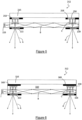
- a reflector 150 may be provided on a glazing 112 as shown in Figure 4 .
- the glazing 112 comprises a first and second glass sheet 116, 118 having an interlayer 120 therebetween.
- the non-opaque ink or outcoupler 122 is provided on surface 4 of the second sheet 118.
- a black obscuration band print 128 is provided at each side of the outcoupler 122.
- a reflector 150 is provided on the first glass sheet 116, on an interior facing surface 130 i.e. surface 2 of the glazing.
- the reflector 150 comprises a light diffusing reflective material, preferably a white or metallic effect material, preferably an enamel ink for automotive use.
- a suitable white ink would be that manufactured by Ferro their reference 194002.
- the reflector 150 causes a boost in the light output at surface 4 because emission through the first glass sheet 116 is substantially prevented. Specifically, light A' is reflected from reflector 150 and is scattered towards the outcoupler 122 (indicated by arrows C). The scattered light that strikes the outcoupler 122 at high angles of incidence will emerge therefrom causing the area of the outcoupler to emit light and become luminous (indicated by arrows A). Provision of the black print 128 helps to focus the area of illumination as light hitting the black print 128 will either be absorbed or reflected, in so doing, this reduces the direct visibility of the reflector 150 other than through the outcoupler 122.
- FIG. 5 shows a further embodiment of the invention of Figure 4 wherein a glazing 212 comprises an additional black print 258 on surface 2.
- the black band print 258 is adjacent either edge of a reflector 250. In so doing, reflected light is from a specified area 250.
- Such an arrangement enables decorative or patterned designs to be created.
- Figure 6 shows an embodiment of the invention having a glazing 312 in which the reflector 350 is printed on top of a surface 2 black print 368.
- the black print 368 provides a uniform appearance from above the glazing, and also acts to block any stray light which may pass through the reflector 350 and therefore all light is reflected providing maximum possible illumination to the cabin.
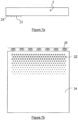
- the non-opaque ink may be provided in the form of an obscuration band for an automotive glazing, replacing black band print.
- the non-opaque ink is printed on the exterior surface 24 (surface 4) of the glazing 2.
- the ink 22 comprises a plurality of dots extending from the edge of the glazing. LEDs 26 are located around the periphery of the glazing to ensure a waveguide is created through the second glass sheet.
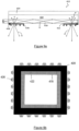
- the non-opaque ink may be arranged as a number of strips 60 on the surface of a glazing as shown in Figures 8 . Each of the strips 60 are within a black print obscuration band 70.
- Figures 9 show an alternative arrangement of a glazing 412 wherein a first black obscuration band print 428 is provided on surface 4 of the second glass sheet, adjacent the non-opaque ink 422, and a second black print 478 is provided on the surface of the non-opaque ink 422 as shown in Figure 9a .
- a first black obscuration band print 428 is provided on surface 4 of the second glass sheet, adjacent the non-opaque ink 422, and a second black print 478 is provided on the surface of the non-opaque ink 422 as shown in Figure 9a .
- an illuminated edge is created to the obscuration band.
- FIG 10 shows a further embodiment of the invention, similar to that of Figure 6 wherein a glazing 512 has a reflector 550 printed on top of a surface 2 black print 568.
- the non opaque ink 522 has been extended to a length substantially the same as the surface 2 black print 568.
- a second black print 578 is provided on top of a section of the non-opaque ink 522. In this way, some light that passes beyond the outcoupling window is still scattered and so does not continue to channel along the second ply. In so doing, the light intensity that passes into the transparent area is reduced.
- the visibility of defects in the transparent part of the glass is minimised.
- a light source adjacent a glazing having a non-opaque ink on surface 4 of a laminated glazing gives illumination to the interior of a cabin of a vehicle.
- the illumination is spread substantially evenly across the glazing allowing for an increase in brightness and uniformity of illumination throughout the cabin.
- the non-opaque ink can be applied during standard automotive glazing processing, without modification to a press bending or sag bending process. This is because said ink is applied to surface 4 of the glazing which does not come into contact with process moulds or rollers.
Landscapes
- Physics & Mathematics (AREA)
- Engineering & Computer Science (AREA)
- Mechanical Engineering (AREA)
- General Physics & Mathematics (AREA)
- Optics & Photonics (AREA)
- Laminated Bodies (AREA)
Description
- The present invention relates to a glazing for a vehicle.
- Vehicles, for example cars and buses, have a number of window openings in their bodywork into which glazings may be fitted; the glazings include windscreens, rear window glazings, side window glazings and roof glazings. In a typical car, the windscreen is a laminated glazing (i.e. having two plies of glazing material joined together by a ply of interlayer material extending between them) for safety reasons, and the remainder of the glazings are usually toughened glass.
- Most vehicles have courtesy lights provided in the cabin, typically adjacent the glazing. The lights are often located above passenger windows and adjacent the rearview mirror. The lights give a degree of illumination, providing the driver or passenger with sufficient light to safely enter the vehicle. However, the illumination is limited and the light does not reach, for example, a foot-well. In order to address this problem, it is known to provide additional lighting toward the base of a door. Disadvantageously, such lights provide minimal brightness and are a drain on the vehicle battery.
- It is known to provide a vehicle glazing with a means of integrated lighting.
WO 2005/054915 describes one example of such a glazing. It discloses a "light-guiding assembly" in the form of a laminated vehicle roof. The assembly comprises two sheets of glass joined together by a polymeric laminating interlayer material, and a means of integrated lighting in the form of light-coupling means for coupling light into the interlayer material. "Scattering centres" of highly reflective pigments are located on the surface of the interlayer material to allow light to exit the glazing creating a brightening effect of the vehicle roof. Disadvantageously, the printing of the interlayer takes place separate from the printing and processing of the automotive glazing. As such, the overall cost of production is increased which is economically undesirable. - It is an object of the present invention to provide a glazing which enables improved illumination for a vehicle cabin.
- According to of the present invention there is provided a glazing for a vehicle as set out in independent claim 1.
- Light reflects off surfaces in a known manner, in accordance with laws of reflection. When a light wave crosses a boundary between materials with different kinds of refractive indices, the wave will be partially refracted at the boundary surface, and partially reflected. However, if the angle of incidence is greater (i.e. the direction of propagation is closer to being parallel to the boundary) than the critical angle, the angle of incidence at which light is refracted such that it travels along the boundary, then the wave will not cross the boundary and instead be totally reflected back internally. This can only occur where the wave travels from a medium with a higher refractive index [n1] to one with a lower refractive index [n2].
- The critical angle θ c is calculated according to

- For example, for glass to air n1 = 1.51 and n2 = 1.00, and so θ c = 41.4° from normal (perpendicular to the boundary). However, for glass to interlayer material (e.g. PVB), n1 = 1.51 and n2 = 1.48, and so θc = 78.6° from normal and so light will be totally reflected.
- If light is coupled into the glass at an edge, for a critical angle of θ c, the minimum distance in from the glass edge at which total internal reflection occurs for all light rays is :

- Therefore, for a typical automotive glazing having a glass edge 2.1mm thick (y) and a critical angle of 78.6°, light rays which first meet the glass/PVB interface more than about 10mm from the edge will be totally internally reflected in the second ply and not pass into the PVB.
- In the present invention, provision of the light scattering means on the exterior surface of the second ply is advantageous. Primarily, said means causes light that would be totally internally reflected due to the refractive index differential between glass/air, to become scattered and thus be emitted, creating a brightening effect in the vehicle cabin.
- In this arrangement, a percentage of the coupled light that enters the second ply is scattered out through the light scattering means, a proportion is reflected along the second ply, and a portion is scattered through the interlayer and may pass through the first ply.
- Preferably, the light source is mounted with respect to the second ply such that substantially all of the light exiting the light source is directed into the second ply. The light scattering means is provided on
surface 4 of the glazing.Surface 4 is commonly understood to mean the surface of a laminated glazing which faces the interior or cabin of a vehicle. - During production of an automotive glazing, it is important that nothing impedes the press bending or sag bending process and so, for example, surface printing must be applied to a surface remote from a bending mould or sag bending rollers. Consequently, known processes print an obscuration black band on
surface 2 orsurface 4 of the glazing. In the present invention, the light scattering means is printed onsurface 4, in keeping with automotive glazing processes. As such, minimal adaption of existing processes is required in order to implement the invention which is economically advantageous. - The light scattering means comprise a non-opaque ink. The non-opaque ink is a semi-transparent or a translucent ink. Preferably, said ink comprises a suspension of frits, preferably glass frits, and preferably inorganic pigments in a preferably organic medium (preferably resins, solvents and additives), and is preferably an IR-drying glass enamel. An example of said ink is that supplied by Johnson Matthey B.V, Fregatweg 38, Maastricht, The Netherlands, product reference AF3901-654-63 or AF3900-654-63. An alternative ink is one manufactured by Ferro product reference 104001.
- Preferably, the non-opaque ink is provided as at least one line on the glazing. Preferably, said ink is provided as a plurality of discontinuous lines or dots on the surface of the glazing. The ink may comprise at least one shaped area on the surface of the glazing. Preferably, the ink is applied by a screen printing process. The ink may be provided as an automotive glazing obscuration band.
- Preferably, the ink is between 5 to 100µm in thickness on the glazing when fired, preferably between 10 to 50 µm, most preferably between 20 to 30 µm.
- Preferably, a reflector is provided on a surface of the first or second ply. Preferably, the reflector is provided on an inner facing surface of the glazing. Preferably, the reflector is provided adjacent the interlayer. Most preferably, the reflector is provided on
surface 2 of the glazing. - In a most preferred arrangement, the reflector is provided on
surface 2 of a laminated glazing and the light scattering means, preferably the non-opaque ink is provided onsurface 4. Preferably, the reflector is of the same size and configuration to the light scattering means. Preferably, the reflector is positioned behind the light scattering means in the laminate arrangement. The reflector onsurface 2, preferably behind the light scattering means onsurface 4, boosts the visible light throughsurface 4. - Preferably, the reflector comprises an ink. Most preferably, the reflector comprises a light diffusing reflective material, preferably a white or metallic effect material, for example a material having an outward appearance of a metal, including a highly reflective material, most preferably an enamel ink for automotive use. For example, a suitable white ink would be that manufactured by Ferro their reference 194002.
- Preferably, the reflector ink is between 5 to 100µm in thickness on the glazing when fired, preferably between 10 to 50 µm, most preferably between 20 to 30 µm.
- Advantageously, the reflector causes light which is scattered away from the second ply to be reflected back towards said ply. In so doing, the illumination in the vehicle cabin is boosted.
- An opaque ink is provided on at least a surface of the glazing. The opaque ink is provided adjacent the light scattering means on
surface 4 of the glazing. The opaque ink, preferably a black ink may be provided behind and/or on top of at least a portion of the light scattering means. - Preferably, the opaque print is provided adjacent at least a portion of the reflector. Preferably, the opaque print is provided behind and/or on top of the reflector, preferably being located on
surface 2 of the glazing. - Preferably, the non-opaque ink, and/or the reflector, and/or the opaque ink are screen printed on to the glazing in a multi-pass screen printing process.
- Preferably, the or each ply of glass is a pane of extra clear glass (glass having greater than 85 % visible light transmission (measured with Illuminant A) at thicknesses preferably from 2 to 20 mm. Preferably, at least one ply of glazing is a pane of low-iron, for example a ply of OPTIWHITE™ glass available from Pilkington Group Limited, having a visible light transmission of greater than 85 % preferably at thicknesses in the range of 2 to 20 mm.
- Advantageously, the use of such low iron glazing minimises the green colour produced as a result of light absorption in a high iron glazing.
- A ply of the glazing may be body-tinted glass, the composition of which includes one or more of the following colourants: iron oxide, cobalt oxide, selenium, chromium oxide, titanium oxide, manganese oxide, copper oxide, vanadium oxide, nickel oxide. The reflector may be provided on the body tinted ply.
- Preferably, the first glass ply is a body-tinted glass and the second glass ply is a low iron glass, preferably OPTIWHITE™.
- The plies of glazing material may be flat or they may be curved. Each pane may be between 0.5 and 25 mm in thickness, preferably between 1 and 5 mm. The overall thickness of the glazing may therefore be between 1.5 and 100 mm, preferably between 2 and 50 mm, and further preferably between 2.5 and 20 mm. A solar control coating may be provided on a surface of at least one pane of glazing material or within the interlayer.
- Preferably, the interlayer material may be any material known in the art that is suitable for forming a laminate and providing the required differential in refractive index. Preferably, the interlayer is polyvinylbutyral ("PVB"). The interlayer may be polyvinyl chloride ("PVC"), polyurethane ("PU") or an ethyl vinyl acetate ("EVA"). Preferably, the interlayer is provided in a thickness of between 0.38 and 1.1 mm, most preferably 0.76 mm.
- Preferably, the light source comprises at least one LED. Preferably, the or each light source is mounted with respect to an edge of a ply of the glazing. In this manner, the ply functions as a waveguide for the coupled-in light. When a plurality of light sources is provided, preferably each is mounted with respect to different edges of the glazing.
- An embodiment of the invention will now be described, by way of example only, with reference to the accompanying drawings, wherein:
-
Figure 1 shows a schematic perspective view part of a vehicle incorporating a typical glazing; -
Figure 2 shows a schematic perspective view of part of a vehicle incorporating a glazing according to the present invention; -
Figure 3 shows a schematic sectional side view of a glazing not according to the present invention; -
Figure 4 shows a schematic sectional side view of an alternative embodiment of a glazing according to the present invention; -
Figure 5 shows a schematic sectional side view of an alternative embodiment of a glazing according to the present invention; -
Figure 6 shows a schematic sectional side view of an alternative embodiment of a glazing according to the present invention; -
Figures 7a and 7b show a schematic side view and a schematic plan view respectively of an alternative glazing not according to the present invention; -
Figures 8a and 8b show a schematic side view and a schematic plan view respectively of an alternative embodiment of a glazing according to the present invention; -
Figures 9a and 9b show a schematic sectional side view and a schematic plan view respectively of an alternative embodiment of a a glazing according to the present invention; and -
Figure 10 shows a schematic sectional side view of a further alternative embodiment of a glazing according to the present invention. -
Figure 1 shows atypical vehicle 2 comprising aroof glazing 4 and side windows 6.Courtesy lights 8 are provided inside the cabin, located above the rear passenger doors.Such lights 8 are generally small and provide a degree of illumination only to their immediate vicinity as illustrated in the figure. -
Figure 2 shows a vehicle 10 incorporating aglazing 12 according to the present invention. A panoramic roof glazing is shown for ease of illustration of the invention but it will be understood by the reader that the invention is not limited to such roof glazings and includes windscreens, rear window glazings, and side window glazings. It is shown inFigure 2 that theglazing 12 provides increased illumination (shown by dotted lines 14) into the cabin when compared with the typical glazing ofFigure 1 . The details of how this is achieved are described below. -
Figure 3 shows aglazing 12 not according to the invention. Theglazing 12 is a laminated glazing comprising a first glass ply orsheet 16 and a second glass ply orsheet 18 bonded together by aninterlayer 20, typically comprising PVB. The first andsecond sheets - Non opaque ink 22 (a light scattering means or outcoupler) is provided on the
second glass sheet 18 as a discontinuous print as shown inFigure 3 . Theink 22 is applied to anexterior surface 24 of thesecond glass sheet 18, i.e. the surface which faces the interior of the cabin, often referred to as "surface 4" of a glazing. - The
ink 22 is applied to thesheet 18 by a conventional automotive screen printing process whereby ink is printed on to a surface of the glazing which does not come into contact with a press bending mould or sag bending rollers, i.e.surface 2 orsurface 4 of a glazing. Ink printed on to surfaces 1 or 3 would smudge and be damaged. - The
non-opaque ink 22 is transparent or preferably translucent. A suitable ink is that supplied by Johnson Matthey B.V, Fregatweg 38, Maastricht, The Netherlands, product reference AF3901-654-63 or AF3900-654-63. Theink 22 comprises a suspension of frits and inorganic pigments in an organic medium (resins, solvents and additives), and is an IR-drying glass enamel in a 2-methoxymethylethoxy propanol carrier medium. An alternative ink is one manufactured by Ferro product reference 104001. - At least one
LED 26 is located adjacent an edge of thesecond sheet 18 to act as an optical coupler. The LED is positioned to ensure that light enters thesecond sheet 18 at an angle greater than the appropriate critical angle θC for total internal reflection at the surfaces ofsheet 18. Arrows B schematically show the resulting path of light coupled into thesecond sheet 18. - In use, when light hits the
ink 22, because the ink is not totally reflective, it acts as a light scattering centre. Light is caused to scatter in all directions, but primarily in two general directions as represented by arrows A, A' in the figures. Light "A" passes through theink 22 and out of the glass to provide illumination to the cabin of the vehicle. Light A' passes through theinterlayer 20 and out through thefirst substrate 16. - In order to maximise the illumination effect, a
reflector 150 may be provided on aglazing 112 as shown inFigure 4 . Theglazing 112 comprises a first andsecond glass sheet 116, 118 having aninterlayer 120 therebetween. The non-opaque ink oroutcoupler 122 is provided onsurface 4 of the second sheet 118. A blackobscuration band print 128 is provided at each side of theoutcoupler 122. Areflector 150 is provided on thefirst glass sheet 116, on an interior facingsurface 130 i.e.surface 2 of the glazing. Thereflector 150 comprises a light diffusing reflective material, preferably a white or metallic effect material, preferably an enamel ink for automotive use. For example, a suitable white ink would be that manufactured by Ferro their reference 194002. - In use, the
reflector 150 causes a boost in the light output atsurface 4 because emission through thefirst glass sheet 116 is substantially prevented. Specifically, light A' is reflected fromreflector 150 and is scattered towards the outcoupler 122 (indicated by arrows C). The scattered light that strikes theoutcoupler 122 at high angles of incidence will emerge therefrom causing the area of the outcoupler to emit light and become luminous (indicated by arrows A). Provision of theblack print 128 helps to focus the area of illumination as light hitting theblack print 128 will either be absorbed or reflected, in so doing, this reduces the direct visibility of thereflector 150 other than through theoutcoupler 122. -
Figure 5 shows a further embodiment of the invention ofFigure 4 wherein aglazing 212 comprises an additionalblack print 258 onsurface 2. Theblack band print 258 is adjacent either edge of areflector 250. In so doing, reflected light is from a specifiedarea 250. Such an arrangement enables decorative or patterned designs to be created. -
Figure 6 shows an embodiment of the invention having aglazing 312 in which thereflector 350 is printed on top of asurface 2black print 368. Theblack print 368 provides a uniform appearance from above the glazing, and also acts to block any stray light which may pass through thereflector 350 and therefore all light is reflected providing maximum possible illumination to the cabin. - The non-opaque ink may be provided in the form of an obscuration band for an automotive glazing, replacing black band print. For example, as shown in
Figures 7 , the non-opaque ink is printed on the exterior surface 24 (surface 4) of theglazing 2. Theink 22 comprises a plurality of dots extending from the edge of the glazing.LEDs 26 are located around the periphery of the glazing to ensure a waveguide is created through the second glass sheet. Alternatively, the non-opaque ink may be arranged as a number ofstrips 60 on the surface of a glazing as shown inFigures 8 . Each of thestrips 60 are within a blackprint obscuration band 70. -
Figures 9 show an alternative arrangement of aglazing 412 wherein a first blackobscuration band print 428 is provided onsurface 4 of the second glass sheet, adjacent thenon-opaque ink 422, and a secondblack print 478 is provided on the surface of thenon-opaque ink 422 as shown inFigure 9a . In this configuration, an illuminated edge is created to the obscuration band. -
Figure 10 shows a further embodiment of the invention, similar to that ofFigure 6 wherein aglazing 512 has areflector 550 printed on top of asurface 2black print 568. - The non
opaque ink 522 has been extended to a length substantially the same as thesurface 2black print 568. A secondblack print 578 is provided on top of a section of thenon-opaque ink 522. In this way, some light that passes beyond the outcoupling window is still scattered and so does not continue to channel along the second ply. In so doing, the light intensity that passes into the transparent area is reduced. Advantageously, the visibility of defects in the transparent part of the glass is minimised. - Advantageously, provision of a light source adjacent a glazing having a non-opaque ink on
surface 4 of a laminated glazing, gives illumination to the interior of a cabin of a vehicle. The illumination is spread substantially evenly across the glazing allowing for an increase in brightness and uniformity of illumination throughout the cabin. - Further, by reducing the amount of light that reaches the open or middle area of the glass, causes a reduction in the visibility of scratches of defects that may be present on the glass.
- Advantageously, the non-opaque ink can be applied during standard automotive glazing processing, without modification to a press bending or sag bending process. This is because said ink is applied to
surface 4 of the glazing which does not come into contact with process moulds or rollers.
Claims (10)
- A glazing (12, 112, 212, 312, 412, 512) for a vehicle, the glazing comprising at least a first ply (16, 116, 216, 316, 416, 516), at least a second ply (18, 118, 218, 318, 418), and an interlayer (20, 120, 220, 320, 420, 520) therebetween,the second ply mountable with respect to a light source (26, 126, 226), the light source being operable to couple light into said second ply,wherein light scattering means (22, 122, 222, 322, 422, 522) comprising a non-opaque ink are provided on an exterior surface (24) of the second ply,the light scattering means being adapted to cause at least a portion of the coupled light to scatter and be transmitted through said scattering means, wherein the non-opaque ink is a semi-transparent or a translucent ink, andan opaque ink (128, 228, 258, 328, 368, 70, 428, 478, 528, 568, 578) is provided on at least a surface of the glazing, whereinthe light scattering means are provided on surface 4 (24) of the glazing and the opaque ink (128, 228, 328, 70, 428, 528) is provided adjacent at least a portion of the light scattering means (22, 122, 222, 322, 422, 522) on surface 4 of the glazing.
- A glazing as claimed in claim 1, wherein the non-opaque ink is provided as a plurality of discontinuous lines or dots on the surface of the glazing.
- A glazing as claimed in claim 1 or 2, wherein a reflector (150, 250, 350, 550) is provided on a surface (130) of the first or second ply.
- A glazing as claimed in claim 3, wherein the reflector is provided on an inner facing surface of the or each ply.
- A glazing as claimed in claim 4, wherein the reflector (150, 250, 350, 550) is provided adjacent the interlayer (120, 220, 320, 520).
- A glazing as claimed in claim 4 or 5, wherein the reflector is provided on surface 2 of the glazing.
- A glazing as claimed in any one of claims 3 to 6, wherein the reflector is of the same size and configuration as the light scattering means.
- A glazing as claimed in any one of claims 3 to 7, wherein the reflector comprises a light diffusing reflective material.
- A glazing as claimed in claim 8, wherein the light diffusing reflective material is a white or metallic effect material.
- A glazing as claimed in any one of the preceding Claims, wherein at least one ply of the glazing is a pane of low-iron glass having a visible light transmission of greater than 85%, preferably at thicknesses in the range of 2 to 20 mm.
Applications Claiming Priority (2)
| Application Number | Priority Date | Filing Date | Title |
|---|---|---|---|
| GB201306726A GB201306726D0 (en) | 2013-04-12 | 2013-04-12 | A glazing |
| PCT/GB2014/051016 WO2014167291A1 (en) | 2013-04-12 | 2014-04-01 | A glazing |
Publications (3)
| Publication Number | Publication Date |
|---|---|
| EP2983909A1 EP2983909A1 (en) | 2016-02-17 |
| EP2983909B1 EP2983909B1 (en) | 2021-06-09 |
| EP2983909B2 true EP2983909B2 (en) | 2024-07-17 |
Family
ID=48537203
Family Applications (1)
| Application Number | Title | Priority Date | Filing Date |
|---|---|---|---|
| EP14715104.7A Active EP2983909B2 (en) | 2013-04-12 | 2014-04-01 | A glazing |
Country Status (3)
| Country | Link |
|---|---|
| EP (1) | EP2983909B2 (en) |
| GB (1) | GB201306726D0 (en) |
| WO (1) | WO2014167291A1 (en) |
Families Citing this family (43)
| Publication number | Priority date | Publication date | Assignee | Title |
|---|---|---|---|---|
| EP3034296A1 (en) * | 2014-12-19 | 2016-06-22 | AGC Glass Europe | Laminated glazing |
| US20170028908A1 (en) * | 2015-08-02 | 2017-02-02 | Henry E. Curtis | Led lighting for an automobile |
| US9902314B1 (en) * | 2016-11-17 | 2018-02-27 | Ford Global Technologies, Llc | Vehicle light system |
| TW201925120A (en) * | 2017-11-08 | 2019-07-01 | 美商康寧公司 | Ceiling lighting system using glass light-guide plate |
| EP3702217B1 (en) * | 2019-03-01 | 2025-08-20 | Inalfa Roof Systems Group B.V. | A transparent roof assembly for a vehicle roof |
| CN113613888A (en) * | 2019-03-21 | 2021-11-05 | 中央硝子株式会社 | Glass with lighting capability |
| CN113677521A (en) * | 2019-03-29 | 2021-11-19 | Agp美洲股份公司 | Lighting laminates with superior aesthetics and brightness |
| DE102020109338B3 (en) * | 2020-04-03 | 2021-05-27 | Webasto SE | Vehicle window with light source and light guide layer |
| EP3925774A1 (en) * | 2020-06-17 | 2021-12-22 | Inalfa Roof Systems Group B.V. | Functional lighting in an obscuration band of a vehicle glazing |
| CN113715727A (en) * | 2020-11-05 | 2021-11-30 | 法国圣戈班玻璃公司 | Light guide layer for vehicle glazing, vehicle glazing and vehicle interior lighting system |
| EP4105678A1 (en) * | 2021-06-18 | 2022-12-21 | HELLA Saturnus Slovenija d.o.o. | Illuminated cover for electromagnetic transmitter and receiver |
| DE102021121195A1 (en) * | 2021-08-16 | 2023-02-16 | Webasto SE | Glass pane of a vehicle glazing with a print |
| EP4392253A1 (en) * | 2021-08-25 | 2024-07-03 | Inalfa Roof Systems Group B.V. | A transparent roof panel assembly for a vehicle roof |
| EP4183575A1 (en) * | 2021-11-22 | 2023-05-24 | Inalfa Roof Systems Group B.V. | A transparent roof panel assembly for a vehicle roof |
| WO2023114743A1 (en) * | 2021-12-14 | 2023-06-22 | Acr Ii Glass America Inc. | Glazing with lighting capabilities |
| DE102021134016B4 (en) | 2021-12-21 | 2024-06-13 | Webasto SE | Method for producing a laminated glass pane |
| CN117279779A (en) * | 2022-01-28 | 2023-12-22 | 法国圣戈班玻璃厂 | Illuminated glazing |
| CN116829349A (en) * | 2022-01-28 | 2023-09-29 | 法国圣戈班玻璃厂 | Illuminated glazing |
| CN117015472A (en) | 2022-03-07 | 2023-11-07 | 法国圣戈班玻璃厂 | Illuminated composite glass panels with reflective edge coating |
| DE102022001884B4 (en) | 2022-05-30 | 2024-05-08 | Mercedes-Benz Group AG | Window assembly for a motor vehicle |
| CN119343563A (en) | 2022-06-10 | 2025-01-21 | 法国圣戈班玻璃厂 | Illuminated panel glass element with reduced light emission via the sides |
| JP2025537457A (en) | 2022-12-12 | 2025-11-18 | サン-ゴバン セキュリット フランス | Illuminating glazing element with coated reflective structure for light coupling - Patent Application 20070122997 |
| DE202022106921U1 (en) | 2022-12-12 | 2023-01-04 | Saint-Gobain SEKURIT Deutschland GmbH | Glazing element with a light-conducting transparent layer |
| WO2024133090A1 (en) | 2022-12-22 | 2024-06-27 | Saint-Gobain Glass France | Illuminated composite pane |
| CN118346946A (en) | 2023-01-13 | 2024-07-16 | 法国圣戈班玻璃厂 | Illuminated glazing element with emissivity reducing coating |
| EP4403355A1 (en) * | 2023-01-20 | 2024-07-24 | Inalfa Roof Systems Group B.V. | Vehicle roof assembly comprising a patterned transparent panel and method of providing a pattern on a transparent element |
| CN120897845A (en) | 2023-03-27 | 2025-11-04 | 法国圣戈班安全玻璃公司 | Illumination window glass element with diffraction holographic elements for coupling in incident light |
| WO2024231137A1 (en) | 2023-05-08 | 2024-11-14 | Saint-Gobain Glass France | Method for producing an illuminated laminated pane having a reflective structure for the incoupling of light |
| EP4731438A1 (en) | 2023-06-22 | 2026-04-29 | Saint-Gobain Sekurit France | Composite pane having a plurality of reflective structures for 3-dimensional illumination |
| WO2025004105A1 (en) * | 2023-06-29 | 2025-01-02 | Saint-Gobain Glass France | A light diffusing ink for coating on a substrate and a coated automotive glazing thereof |
| WO2025026972A1 (en) | 2023-07-31 | 2025-02-06 | Saint-Gobain Glass France | Method for manufacturing an illuminable vehicle roof |
| CN121752432A (en) | 2023-08-15 | 2026-03-27 | 法国圣戈班安全玻璃公司 | Composite pane for luminous glazing element |
| WO2025036660A1 (en) | 2023-08-17 | 2025-02-20 | Saint-Gobain Glass France | Glazing element which can be illuminated and has controllable optical properties |
| WO2025040448A1 (en) | 2023-08-18 | 2025-02-27 | Saint-Gobain Glass France | Foldable panel assembly with light module |
| CN121866233A (en) | 2023-09-25 | 2026-04-14 | 法国圣戈班安全玻璃公司 | Lighting glazing element with emissivity-reducing coating |
| DE102023130347A1 (en) * | 2023-11-02 | 2025-05-08 | Webasto SE | Vehicle glazing with a light-diffusing print |
| DE102023130348A1 (en) * | 2023-11-02 | 2025-05-08 | Webasto SE | Vehicle glazing with a light-diffusing print |
| WO2025119574A1 (en) | 2023-12-08 | 2025-06-12 | Saint-Gobain Sekurit France | Pane for a glazing which can be illuminated three-dimensionally |
| WO2025119575A1 (en) | 2023-12-08 | 2025-06-12 | Saint-Gobain Sekurit France | Composite pane for a glazing which can be illuminated three-dimensionally |
| WO2025190997A1 (en) | 2024-03-14 | 2025-09-18 | Saint-Gobain Sekurit France | Co-extruded multi-layer film |
| WO2026012643A1 (en) | 2024-07-12 | 2026-01-15 | Saint-Gobain Sekurit France | Layer stack for use as a light-coupling element on an optical waveguide |
| WO2026012650A1 (en) | 2024-07-12 | 2026-01-15 | Saint-Gobain Sekurit France | Pane comprising a layer stack |
| WO2026032648A1 (en) | 2024-08-09 | 2026-02-12 | Saint-Gobain Sekurit France | Illuminable glazing element with dichroic coupling-in element |
Citations (1)
| Publication number | Priority date | Publication date | Assignee | Title |
|---|---|---|---|---|
| WO2013110885A1 (en) † | 2012-01-26 | 2013-08-01 | Saint-Gobain Glass France | Illuminating glazing unit for a vehicle |
Family Cites Families (7)
| Publication number | Priority date | Publication date | Assignee | Title |
|---|---|---|---|---|
| FR2809496B1 (en) | 2000-05-23 | 2002-07-12 | Saint Gobain Vitrage | DIFFUSING LAYER |
| US20070098969A1 (en) * | 2003-12-02 | 2007-05-03 | Koninklijke Philips Electronics N.V. | Light-guiding assembly and automotive vehicle roof |
| WO2007077099A1 (en) * | 2006-01-06 | 2007-07-12 | Pilkington Automotive Deutschland Gmbh | Vehicle glazing with light-guiding assembly |
| FR2937710B1 (en) | 2008-10-27 | 2013-05-17 | Saint Gobain | LIGHT EMITTING DIODE MODULE FOR VEHICLE, DIODE SUPPORT, FABRICATIONS |
| FR2955539B1 (en) | 2010-01-26 | 2016-03-25 | Saint Gobain | LUMINOUS VEHICLE GLAZING, MANUFACTURING |
| FR2987323A1 (en) * | 2012-02-23 | 2013-08-30 | Peugeot Citroen Automobiles Sa | Luminous glazing for vehicle i.e. car, has light source comprising transmitter, and extraction unit arranged on one of main faces of glass leaf, where extraction unit comprises focusing unit for focusing extracted light |
| DE102012109900B4 (en) * | 2012-10-17 | 2015-10-15 | Bayerische Motoren Werke Aktiengesellschaft | vehicle glazing |
-
2013
- 2013-04-12 GB GB201306726A patent/GB201306726D0/en not_active Ceased
-
2014
- 2014-04-01 EP EP14715104.7A patent/EP2983909B2/en active Active
- 2014-04-01 WO PCT/GB2014/051016 patent/WO2014167291A1/en not_active Ceased
Patent Citations (1)
| Publication number | Priority date | Publication date | Assignee | Title |
|---|---|---|---|---|
| WO2013110885A1 (en) † | 2012-01-26 | 2013-08-01 | Saint-Gobain Glass France | Illuminating glazing unit for a vehicle |
Also Published As
| Publication number | Publication date |
|---|---|
| EP2983909B1 (en) | 2021-06-09 |
| EP2983909A1 (en) | 2016-02-17 |
| GB201306726D0 (en) | 2013-05-29 |
| WO2014167291A1 (en) | 2014-10-16 |
Similar Documents
| Publication | Publication Date | Title |
|---|---|---|
| EP2983909B2 (en) | A glazing | |
| CN103260918B (en) | Luminous signaling window glass for vehicles | |
| DK3105051T3 (en) | LIGHTING WINDOW WITH OPTICAL ISOLATOR | |
| EP1973762A1 (en) | Vehicle glazing with light-guiding assembly | |
| CN116897104A (en) | Components with lightable panes | |
| US20070098969A1 (en) | Light-guiding assembly and automotive vehicle roof | |
| KR102480290B1 (en) | Light-emitting laminated glazing for vehicles, including inorganic light-emitting diodes, and manufacturing thereof | |
| US20250162286A1 (en) | Illuminating glazed roof | |
| EA025103B1 (en) | Automobile vehicle | |
| CN220682104U (en) | Curved automotive laminate with lighting device | |
| CN114126856B (en) | Laminated glass | |
| US20230086792A1 (en) | Vehicle window structure | |
| CN114103800A (en) | Light emitting assembly of vehicle window light-transmitting piece and vehicle | |
| US20250050716A1 (en) | Transparent roof panel assembly for a vehicle roof | |
| CN116766891A (en) | Vehicle windshield and vehicle | |
| CN117015472A (en) | Illuminated composite glass panels with reflective edge coating | |
| EP4183575A1 (en) | A transparent roof panel assembly for a vehicle roof | |
| JP2001105849A (en) | Edge light device | |
| WO2025071401A1 (en) | Automotive window laminate and method for producing the same | |
| CN119261504A (en) | Glass assembly and window assembly |
Legal Events
| Date | Code | Title | Description |
|---|---|---|---|
| PUAI | Public reference made under article 153(3) epc to a published international application that has entered the european phase |
Free format text: ORIGINAL CODE: 0009012 |
|
| 17P | Request for examination filed |
Effective date: 20151112 |
|
| AK | Designated contracting states |
Kind code of ref document: A1 Designated state(s): AL AT BE BG CH CY CZ DE DK EE ES FI FR GB GR HR HU IE IS IT LI LT LU LV MC MK MT NL NO PL PT RO RS SE SI SK SM TR |
|
| AX | Request for extension of the european patent |
Extension state: BA ME |
|
| DAX | Request for extension of the european patent (deleted) | ||
| STAA | Information on the status of an ep patent application or granted ep patent |
Free format text: STATUS: EXAMINATION IS IN PROGRESS |
|
| 17Q | First examination report despatched |
Effective date: 20191010 |
|
| GRAP | Despatch of communication of intention to grant a patent |
Free format text: ORIGINAL CODE: EPIDOSNIGR1 |
|
| STAA | Information on the status of an ep patent application or granted ep patent |
Free format text: STATUS: GRANT OF PATENT IS INTENDED |
|
| INTG | Intention to grant announced |
Effective date: 20201222 |
|
| GRAS | Grant fee paid |
Free format text: ORIGINAL CODE: EPIDOSNIGR3 |
|
| GRAA | (expected) grant |
Free format text: ORIGINAL CODE: 0009210 |
|
| STAA | Information on the status of an ep patent application or granted ep patent |
Free format text: STATUS: THE PATENT HAS BEEN GRANTED |
|
| RIN1 | Information on inventor provided before grant (corrected) |
Inventor name: VOSS, JONATHAN PETER |
|
| AK | Designated contracting states |
Kind code of ref document: B1 Designated state(s): AL AT BE BG CH CY CZ DE DK EE ES FI FR GB GR HR HU IE IS IT LI LT LU LV MC MK MT NL NO PL PT RO RS SE SI SK SM TR |
|
| REG | Reference to a national code |
Ref country code: GB Ref legal event code: FG4D |
|
| REG | Reference to a national code |
Ref country code: AT Ref legal event code: REF Ref document number: 1400123 Country of ref document: AT Kind code of ref document: T Effective date: 20210615 Ref country code: CH Ref legal event code: EP |
|
| REG | Reference to a national code |
Ref country code: DE Ref legal event code: R096 Ref document number: 602014078010 Country of ref document: DE |
|
| REG | Reference to a national code |
Ref country code: IE Ref legal event code: FG4D |
|
| REG | Reference to a national code |
Ref country code: LT Ref legal event code: MG9D |
|
| PG25 | Lapsed in a contracting state [announced via postgrant information from national office to epo] |
Ref country code: BG Free format text: LAPSE BECAUSE OF FAILURE TO SUBMIT A TRANSLATION OF THE DESCRIPTION OR TO PAY THE FEE WITHIN THE PRESCRIBED TIME-LIMIT Effective date: 20210909 Ref country code: FI Free format text: LAPSE BECAUSE OF FAILURE TO SUBMIT A TRANSLATION OF THE DESCRIPTION OR TO PAY THE FEE WITHIN THE PRESCRIBED TIME-LIMIT Effective date: 20210609 Ref country code: LT Free format text: LAPSE BECAUSE OF FAILURE TO SUBMIT A TRANSLATION OF THE DESCRIPTION OR TO PAY THE FEE WITHIN THE PRESCRIBED TIME-LIMIT Effective date: 20210609 Ref country code: HR Free format text: LAPSE BECAUSE OF FAILURE TO SUBMIT A TRANSLATION OF THE DESCRIPTION OR TO PAY THE FEE WITHIN THE PRESCRIBED TIME-LIMIT Effective date: 20210609 |
|
| REG | Reference to a national code |
Ref country code: AT Ref legal event code: MK05 Ref document number: 1400123 Country of ref document: AT Kind code of ref document: T Effective date: 20210609 |
|
| REG | Reference to a national code |
Ref country code: NL Ref legal event code: MP Effective date: 20210609 |
|
| PG25 | Lapsed in a contracting state [announced via postgrant information from national office to epo] |
Ref country code: GR Free format text: LAPSE BECAUSE OF FAILURE TO SUBMIT A TRANSLATION OF THE DESCRIPTION OR TO PAY THE FEE WITHIN THE PRESCRIBED TIME-LIMIT Effective date: 20210910 Ref country code: LV Free format text: LAPSE BECAUSE OF FAILURE TO SUBMIT A TRANSLATION OF THE DESCRIPTION OR TO PAY THE FEE WITHIN THE PRESCRIBED TIME-LIMIT Effective date: 20210609 Ref country code: NO Free format text: LAPSE BECAUSE OF FAILURE TO SUBMIT A TRANSLATION OF THE DESCRIPTION OR TO PAY THE FEE WITHIN THE PRESCRIBED TIME-LIMIT Effective date: 20210909 Ref country code: RS Free format text: LAPSE BECAUSE OF FAILURE TO SUBMIT A TRANSLATION OF THE DESCRIPTION OR TO PAY THE FEE WITHIN THE PRESCRIBED TIME-LIMIT Effective date: 20210609 Ref country code: SE Free format text: LAPSE BECAUSE OF FAILURE TO SUBMIT A TRANSLATION OF THE DESCRIPTION OR TO PAY THE FEE WITHIN THE PRESCRIBED TIME-LIMIT Effective date: 20210609 |
|
| PG25 | Lapsed in a contracting state [announced via postgrant information from national office to epo] |
Ref country code: ES Free format text: LAPSE BECAUSE OF FAILURE TO SUBMIT A TRANSLATION OF THE DESCRIPTION OR TO PAY THE FEE WITHIN THE PRESCRIBED TIME-LIMIT Effective date: 20210609 Ref country code: RO Free format text: LAPSE BECAUSE OF FAILURE TO SUBMIT A TRANSLATION OF THE DESCRIPTION OR TO PAY THE FEE WITHIN THE PRESCRIBED TIME-LIMIT Effective date: 20210609 Ref country code: NL Free format text: LAPSE BECAUSE OF FAILURE TO SUBMIT A TRANSLATION OF THE DESCRIPTION OR TO PAY THE FEE WITHIN THE PRESCRIBED TIME-LIMIT Effective date: 20210609 Ref country code: PT Free format text: LAPSE BECAUSE OF FAILURE TO SUBMIT A TRANSLATION OF THE DESCRIPTION OR TO PAY THE FEE WITHIN THE PRESCRIBED TIME-LIMIT Effective date: 20211011 Ref country code: AT Free format text: LAPSE BECAUSE OF FAILURE TO SUBMIT A TRANSLATION OF THE DESCRIPTION OR TO PAY THE FEE WITHIN THE PRESCRIBED TIME-LIMIT Effective date: 20210609 Ref country code: CZ Free format text: LAPSE BECAUSE OF FAILURE TO SUBMIT A TRANSLATION OF THE DESCRIPTION OR TO PAY THE FEE WITHIN THE PRESCRIBED TIME-LIMIT Effective date: 20210609 Ref country code: EE Free format text: LAPSE BECAUSE OF FAILURE TO SUBMIT A TRANSLATION OF THE DESCRIPTION OR TO PAY THE FEE WITHIN THE PRESCRIBED TIME-LIMIT Effective date: 20210609 Ref country code: SM Free format text: LAPSE BECAUSE OF FAILURE TO SUBMIT A TRANSLATION OF THE DESCRIPTION OR TO PAY THE FEE WITHIN THE PRESCRIBED TIME-LIMIT Effective date: 20210609 Ref country code: SK Free format text: LAPSE BECAUSE OF FAILURE TO SUBMIT A TRANSLATION OF THE DESCRIPTION OR TO PAY THE FEE WITHIN THE PRESCRIBED TIME-LIMIT Effective date: 20210609 |
|
| PG25 | Lapsed in a contracting state [announced via postgrant information from national office to epo] |
Ref country code: PL Free format text: LAPSE BECAUSE OF FAILURE TO SUBMIT A TRANSLATION OF THE DESCRIPTION OR TO PAY THE FEE WITHIN THE PRESCRIBED TIME-LIMIT Effective date: 20210609 |
|
| REG | Reference to a national code |
Ref country code: DE Ref legal event code: R026 Ref document number: 602014078010 Country of ref document: DE |
|
| PLBI | Opposition filed |
Free format text: ORIGINAL CODE: 0009260 |
|
| PLAX | Notice of opposition and request to file observation + time limit sent |
Free format text: ORIGINAL CODE: EPIDOSNOBS2 |
|
| 26 | Opposition filed |
Opponent name: SAINT-GOBAIN GLASS FRANCE Effective date: 20220308 |
|
| PG25 | Lapsed in a contracting state [announced via postgrant information from national office to epo] |
Ref country code: DK Free format text: LAPSE BECAUSE OF FAILURE TO SUBMIT A TRANSLATION OF THE DESCRIPTION OR TO PAY THE FEE WITHIN THE PRESCRIBED TIME-LIMIT Effective date: 20210609 |
|
| PG25 | Lapsed in a contracting state [announced via postgrant information from national office to epo] |
Ref country code: AL Free format text: LAPSE BECAUSE OF FAILURE TO SUBMIT A TRANSLATION OF THE DESCRIPTION OR TO PAY THE FEE WITHIN THE PRESCRIBED TIME-LIMIT Effective date: 20210609 |
|
| PLBB | Reply of patent proprietor to notice(s) of opposition received |
Free format text: ORIGINAL CODE: EPIDOSNOBS3 |
|
| PG25 | Lapsed in a contracting state [announced via postgrant information from national office to epo] |
Ref country code: IT Free format text: LAPSE BECAUSE OF FAILURE TO SUBMIT A TRANSLATION OF THE DESCRIPTION OR TO PAY THE FEE WITHIN THE PRESCRIBED TIME-LIMIT Effective date: 20210609 |
|
| REG | Reference to a national code |
Ref country code: CH Ref legal event code: PL |
|
| REG | Reference to a national code |
Ref country code: BE Ref legal event code: MM Effective date: 20220430 |
|
| PG25 | Lapsed in a contracting state [announced via postgrant information from national office to epo] |
Ref country code: MC Free format text: LAPSE BECAUSE OF FAILURE TO SUBMIT A TRANSLATION OF THE DESCRIPTION OR TO PAY THE FEE WITHIN THE PRESCRIBED TIME-LIMIT Effective date: 20210609 Ref country code: LU Free format text: LAPSE BECAUSE OF NON-PAYMENT OF DUE FEES Effective date: 20220401 Ref country code: LI Free format text: LAPSE BECAUSE OF NON-PAYMENT OF DUE FEES Effective date: 20220430 Ref country code: CH Free format text: LAPSE BECAUSE OF NON-PAYMENT OF DUE FEES Effective date: 20220430 |
|
| PG25 | Lapsed in a contracting state [announced via postgrant information from national office to epo] |
Ref country code: BE Free format text: LAPSE BECAUSE OF NON-PAYMENT OF DUE FEES Effective date: 20220430 |
|
| PG25 | Lapsed in a contracting state [announced via postgrant information from national office to epo] |
Ref country code: IE Free format text: LAPSE BECAUSE OF NON-PAYMENT OF DUE FEES Effective date: 20220401 |
|
| P01 | Opt-out of the competence of the unified patent court (upc) registered |
Effective date: 20230516 |
|
| APAH | Appeal reference modified |
Free format text: ORIGINAL CODE: EPIDOSCREFNO |
|
| APBM | Appeal reference recorded |
Free format text: ORIGINAL CODE: EPIDOSNREFNO |
|
| APBP | Date of receipt of notice of appeal recorded |
Free format text: ORIGINAL CODE: EPIDOSNNOA2O |
|
| APBU | Appeal procedure closed |
Free format text: ORIGINAL CODE: EPIDOSNNOA9O |
|
| PG25 | Lapsed in a contracting state [announced via postgrant information from national office to epo] |
Ref country code: HU Free format text: LAPSE BECAUSE OF FAILURE TO SUBMIT A TRANSLATION OF THE DESCRIPTION OR TO PAY THE FEE WITHIN THE PRESCRIBED TIME-LIMIT; INVALID AB INITIO Effective date: 20140401 |
|
| PG25 | Lapsed in a contracting state [announced via postgrant information from national office to epo] |
Ref country code: MK Free format text: LAPSE BECAUSE OF FAILURE TO SUBMIT A TRANSLATION OF THE DESCRIPTION OR TO PAY THE FEE WITHIN THE PRESCRIBED TIME-LIMIT Effective date: 20210609 Ref country code: CY Free format text: LAPSE BECAUSE OF FAILURE TO SUBMIT A TRANSLATION OF THE DESCRIPTION OR TO PAY THE FEE WITHIN THE PRESCRIBED TIME-LIMIT Effective date: 20210609 |
|
| PUAH | Patent maintained in amended form |
Free format text: ORIGINAL CODE: 0009272 |
|
| STAA | Information on the status of an ep patent application or granted ep patent |
Free format text: STATUS: PATENT MAINTAINED AS AMENDED |
|
| PG25 | Lapsed in a contracting state [announced via postgrant information from national office to epo] |
Ref country code: TR Free format text: LAPSE BECAUSE OF FAILURE TO SUBMIT A TRANSLATION OF THE DESCRIPTION OR TO PAY THE FEE WITHIN THE PRESCRIBED TIME-LIMIT Effective date: 20210609 |
|
| 27A | Patent maintained in amended form |
Effective date: 20240717 |
|
| AK | Designated contracting states |
Kind code of ref document: B2 Designated state(s): AL AT BE BG CH CY CZ DE DK EE ES FI FR GB GR HR HU IE IS IT LI LT LU LV MC MK MT NL NO PL PT RO RS SE SI SK SM TR |
|
| REG | Reference to a national code |
Ref country code: DE Ref legal event code: R102 Ref document number: 602014078010 Country of ref document: DE |
|
| PG25 | Lapsed in a contracting state [announced via postgrant information from national office to epo] |
Ref country code: MT Free format text: LAPSE BECAUSE OF FAILURE TO SUBMIT A TRANSLATION OF THE DESCRIPTION OR TO PAY THE FEE WITHIN THE PRESCRIBED TIME-LIMIT Effective date: 20210609 |
|
| PGFP | Annual fee paid to national office [announced via postgrant information from national office to epo] |
Ref country code: DE Payment date: 20250417 Year of fee payment: 12 |
|
| PGFP | Annual fee paid to national office [announced via postgrant information from national office to epo] |
Ref country code: FR Payment date: 20250428 Year of fee payment: 12 |
|
| PGFP | Annual fee paid to national office [announced via postgrant information from national office to epo] |
Ref country code: GB Payment date: 20260324 Year of fee payment: 13 |