EP2983590B1 - Computerized tomography (ct) imaging system with improved x-ray tube mount - Google Patents
Computerized tomography (ct) imaging system with improved x-ray tube mount Download PDFInfo
- Publication number
- EP2983590B1 EP2983590B1 EP14782465.0A EP14782465A EP2983590B1 EP 2983590 B1 EP2983590 B1 EP 2983590B1 EP 14782465 A EP14782465 A EP 14782465A EP 2983590 B1 EP2983590 B1 EP 2983590B1
- Authority
- EP
- European Patent Office
- Prior art keywords
- ray tube
- housing
- assembly
- rotating disk
- mounting
- Prior art date
- Legal status (The legal status is an assumption and is not a legal conclusion. Google has not performed a legal analysis and makes no representation as to the accuracy of the status listed.)
- Not-in-force
Links
- 238000003384 imaging method Methods 0.000 title claims description 8
- 238000003325 tomography Methods 0.000 title description 4
- 238000013170 computed tomography imaging Methods 0.000 claims description 21
- 238000000034 method Methods 0.000 claims description 5
- 238000002591 computed tomography Methods 0.000 claims description 3
- 210000003484 anatomy Anatomy 0.000 description 7
- 238000005094 computer simulation Methods 0.000 description 3
- 238000010276 construction Methods 0.000 description 2
- 238000002059 diagnostic imaging Methods 0.000 description 2
- 238000004458 analytical method Methods 0.000 description 1
- 238000012986 modification Methods 0.000 description 1
- 230000004048 modification Effects 0.000 description 1
- 230000000149 penetrating effect Effects 0.000 description 1
- 238000012216 screening Methods 0.000 description 1
Images






Classifications
-
- H—ELECTRICITY
- H05—ELECTRIC TECHNIQUES NOT OTHERWISE PROVIDED FOR
- H05G—X-RAY TECHNIQUE
- H05G1/00—X-ray apparatus involving X-ray tubes; Circuits therefor
- H05G1/02—Constructional details
- H05G1/04—Mounting the X-ray tube within a closed housing
-
- A—HUMAN NECESSITIES
- A61—MEDICAL OR VETERINARY SCIENCE; HYGIENE
- A61B—DIAGNOSIS; SURGERY; IDENTIFICATION
- A61B6/00—Apparatus or devices for radiation diagnosis; Apparatus or devices for radiation diagnosis combined with radiation therapy equipment
- A61B6/02—Arrangements for diagnosis sequentially in different planes; Stereoscopic radiation diagnosis
- A61B6/03—Computed tomography [CT]
- A61B6/032—Transmission computed tomography [CT]
- A61B6/035—Mechanical aspects of CT
-
- A—HUMAN NECESSITIES
- A61—MEDICAL OR VETERINARY SCIENCE; HYGIENE
- A61B—DIAGNOSIS; SURGERY; IDENTIFICATION
- A61B6/00—Apparatus or devices for radiation diagnosis; Apparatus or devices for radiation diagnosis combined with radiation therapy equipment
- A61B6/40—Arrangements for generating radiation specially adapted for radiation diagnosis
-
- A—HUMAN NECESSITIES
- A61—MEDICAL OR VETERINARY SCIENCE; HYGIENE
- A61B—DIAGNOSIS; SURGERY; IDENTIFICATION
- A61B6/00—Apparatus or devices for radiation diagnosis; Apparatus or devices for radiation diagnosis combined with radiation therapy equipment
- A61B6/44—Constructional features of apparatus for radiation diagnosis
- A61B6/4429—Constructional features of apparatus for radiation diagnosis related to the mounting of source units and detector units
-
- G—PHYSICS
- G01—MEASURING; TESTING
- G01N—INVESTIGATING OR ANALYSING MATERIALS BY DETERMINING THEIR CHEMICAL OR PHYSICAL PROPERTIES
- G01N23/00—Investigating or analysing materials by the use of wave or particle radiation, e.g. X-rays or neutrons, not covered by groups G01N3/00 – G01N17/00, G01N21/00 or G01N22/00
- G01N23/02—Investigating or analysing materials by the use of wave or particle radiation, e.g. X-rays or neutrons, not covered by groups G01N3/00 – G01N17/00, G01N21/00 or G01N22/00 by transmitting the radiation through the material
- G01N23/04—Investigating or analysing materials by the use of wave or particle radiation, e.g. X-rays or neutrons, not covered by groups G01N3/00 – G01N17/00, G01N21/00 or G01N22/00 by transmitting the radiation through the material and forming images of the material
- G01N23/046—Investigating or analysing materials by the use of wave or particle radiation, e.g. X-rays or neutrons, not covered by groups G01N3/00 – G01N17/00, G01N21/00 or G01N22/00 by transmitting the radiation through the material and forming images of the material using tomography, e.g. computed tomography [CT]
-
- G—PHYSICS
- G01—MEASURING; TESTING
- G01N—INVESTIGATING OR ANALYSING MATERIALS BY DETERMINING THEIR CHEMICAL OR PHYSICAL PROPERTIES
- G01N2223/00—Investigating materials by wave or particle radiation
- G01N2223/30—Accessories, mechanical or electrical features
- G01N2223/308—Accessories, mechanical or electrical features support of radiation source
Definitions
- This invention relates to imaging systems in general, and more particularly to computerized tomography (CT) imaging systems.
- CT computerized tomography
- in the medical field it can be desirable to image the interior of a patient's body so as to allow internal body structures to be viewed without physically penetrating the skin of the patient.
- in the security field it can be desirable to image the interior of a container and/or carrying case so as to allow the contents of the container and/or carrying case to be viewed without physically opening the container and/or carrying case.
- CT imaging systems generally operate by directing X-rays into the body from a variety of positions, detecting the X-rays passing through the body, and then processing the detected X-rays so as to build a computer model of the patient's anatomy. This computer model can then be visualized so as to provide images of the patient's anatomy.
- CT imaging system 5 generally comprises a torus 10 which is supported by a base 15. Torus 10 and base 15 together comprise a frame for CT imaging system 5.
- a center opening 20 (which is sometimes referred to as an axial opening) is formed in torus 10. Center opening 20 receives the patient anatomy which is to be scanned.
- torus 10 generally comprises an X-ray tube assembly 25, an X-ray detector assembly 30, and a rotating disk assembly 35.
- X-ray tube assembly 25 and X-ray detector assembly 30 are mounted to rotating disk assembly 35 in diametrically-opposing relation, such that the X-ray beam 40 (generated by X-ray tube assembly 25 and detected by X-ray detector assembly 30) is passed through the patient anatomy disposed in center opening 20.
- X-ray tube assembly 25 and X-ray detector assembly 30 are mounted on rotating disk assembly 35 so that they are rotated as a unit concentrically about center opening 20, X-ray beam 40 will be passed through the patient's anatomy and detected along a full range of radial positions, so as to enable CT imaging system 5 to create a "slice" image of the anatomy penetrated by the X-ray beam.
- CT imaging system 5 By moving the patient relative to CT imaging system 5 during scanning (or, alternatively, by moving CT imaging system 5 relative to the patient during scanning), a series of slice images can be acquired, and thereafter appropriately processed, so as to create a three-dimensional (3D) computer model of the scanned anatomy.
- X-ray tube assembly 25 and X-ray detector assembly 30 are mounted on rotating disk assembly 35 so that they are rotated as a unit concentrically about center opening 20.
- X-ray tube assembly 25 is mounted to rotating disk assembly 35 using an X-ray tube mount 45.
- X-ray tube mount 45 comprises a housing which is typically formed in two sections, an outer section 50 and an inner section 55, with X-ray tube assembly 25 being captured between outer section 50 and inner section 55.
- the terms "outer” and “inner” are characterized in the context of the center of rotation of rotating disk assembly 35, i.e., inner section 55 is disposed closer to the center of rotation of rotating disk assembly 35 than outer section 50.
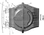
- Outer section 50 of X-ray tube mount 45 is secured to rotating disk assembly 35, whereby to secure X-ray tube mount 45 (and hence X-ray tube assembly 25) to rotating disk assembly 35. More particularly, outer section 50 of X-ray tube mount 45 comprises two feet 60 which are secured to rotating disk assembly 35 via bolts 63 which extend through holes 65 in feet 60 and engage drum mounts 66 (e.g., brackets). Thus, holes 65 in feet 60 provide mounting constructs for mounting X-ray tube mount 45 to rotating disk assembly 35. Note that holes 65 and bolts 63 are disposed at the outer end of X-ray tube mount 45, i.e., near the outer circumference of rotating disk assembly 35.
- outermost portion of outer section 50 of X-ray tube mount 45 comprises first and second lateralmost edges 67A, 67B, and that holes 65 (i.e., the mounting constructs) are disposed laterally inboard of first and second lateralmost edges 67A, 67B.
- Inner section 55 of X-ray tube mount 45 includes a window 70 which emits the X-rays from X-ray tube assembly 25.
- X-ray tube assembly 25 generally comprises a so-called "moving anode” X-ray tube.
- the anode 71 ( Fig. 6 ) of the X-ray tube assembly 25 is mounted on a shaft 72 which is rotated at a high rate of speed (e.g., up to 10,000 revolutions per minute) within the X-ray tube assembly.
- the cathode 73 emits electrons which are drawn to anode 71, with X-rays 40 being emitted off the anode and passing out window 70.
- cathode 73 is radially displaced from the axis of rotation 74 of anode 71 (which axis of rotation 74 is sometimes referred to as "the longitudinal axis of the X-ray tube"). It should also be appreciated that in a moving anode X-ray tube, delicate bearings must be provided for shaft 72, etc., in order to sustain the high rate of rotation required for the moving anode.
- any instability in the mounting of X-ray tube assembly 25 to rotating disk assembly 35 can produce variations in the X-ray beam characteristics, and hence can negatively affect the quality of the images generated by CT imaging system 5.
- X-ray tube assembly 25 typically contains rapidly moving parts (e.g., an anode rotating at up to 10,000 revolutions per minute)
- any instability in the mounting of X-ray tube assembly 25 to rotating disk assembly 35 can cause excessive wear of the parts (e.g., bearings) within X-ray tube assembly 25, which can shorten the life of the X-ray tube assembly.
- excessive wear of the parts (e.g., bearings) within X-ray tube assembly 25 is undesirable.
- the aforementioned X-ray tube mount 45 (comprising outer section 50 and inner section 55, with outer section 50 comprising feet 60 which are secured to rotating disk assembly 35 via bolts 63 which extend through holes 65 in feet 60 and engage drum mounts 66) has performed acceptably.
- interest has now arisen in rotating the rotating disk assembly 35 with significantly increased speeds, e.g., at 270 revolutions per minute.
- the forces imposed on X-ray tube assembly 25 and X-ray tube mount 45 are quite large, and the conventional X-ray tube mount 45 has proven incapable of providing the requisite stability for X-ray tube assembly 25 as rotating disk assembly 35 is rotated.
- instability in the mounting of X-ray tube assembly 25 to rotating disk assembly 35 has negatively affected the quality of the images generated by CT imaging system 5 and has caused excessive wear of the parts (e.g., bearings) within X-ray tube assembly 25, which shortens the life of the X-ray tube assembly.
- US2003/035506 discloses a system and a method for mounting an X-ray tube within a CT scanner.
- a new and improved X-ray tube mount is needed for mounting the X-ray tube assembly to the rotating disk assembly in a CT imaging system.
- the invention is defined by claims 1, 8 and 9.
- the present invention provides a new and improved X-ray tube mount for mounting the X-ray tube assembly to the rotating disk assembly in a CT imaging system.
- this new and improved X-ray tube mount provides significantly increased stability for an X-ray tube assembly, such that the rotating disk assembly can be rotated with significantly increased speeds, e.g., 270 revolutions per minute, while still providing the requisite stability for the X-ray tube assembly.
- an X-ray tube mount for mounting an X-ray tube assembly to the rotating disk assembly of a CT imaging system, said X-ray tube mount comprising:
- apparatus comprising:
- a method for scanning an object comprising:
- the present invention provides a new and improved X-ray tube mount for mounting the X-ray tube assembly to the rotating disk assembly in a CT imaging system.
- this new and improved X-ray tube mount provides significantly increased stability for an X-ray tube assembly, such that the rotating disk assembly can be rotated with significantly increased speeds, e.g., 270 revolutions per minute, while still providing the requisite stability for the X-ray tube assembly.
- the new and improved X-ray tube mount 145 for mounting X-ray tube assembly 25 to rotating disk assembly 35.
- the new and improved X-ray tube mount 145 comprises a housing which is formed in two sections, an outer section 150 and an inner section 155, with X-ray tube assembly 25 being captured to X-ray tube mount 145 between outer section 150 and inner section 155.
- the terms "outer” and “inner” are characterized in the context of the center of rotation of rotating disk assembly 35, i.e., inner section 155 lies closer to the center of rotation of rotating disk assembly 35 than outer section 150.
- Inner section 155 is secured to rotating disk assembly 35, whereby to secure X-ray tube mount 145 (and hence X-ray tube assembly 25) to rotating disk assembly 35. More particularly, with the present invention, inner section 155 of X-ray tube mount 145 comprises a pair of flanges 160 which extend parallel to the longitudinal axis of X-ray tube assembly 25 (i.e., parallel to the axis of rotation 74 of anode 71) and are secured to rotating disk assembly 35 via bolts 163 which extend through holes 165 in flanges 160 and engage drum mounts 166 (e.g., brackets). Thus, holes 165 in flanges 160 provide mounting constructs for mounting X-ray tube mount 145 to rotating disk assembly 35.
- outermost portion of outer section 150 of X-ray tube mount 145 comprises first and second lateralmost edges 167A, 167B, and that holes 165 in flanges 160 of inner section 155 (i.e., the mounting constructs) are disposed laterally outboard of first and second lateralmost edges 167A, 167B.
- holes 165 in flanges 160 of the new and improved X-ray tube mount 145 are disposed outboard of holes 65 in feet 60 of conventional X-ray tube mount 45 (note the distance X in Figs. 4 and 5 versus the distance X+ ⁇ in Figs. 10 and 11 ), and holes 165 in flanges 160 of improved X-ray tube mount 145 are disposed closer to the center of rotation of rotating disk assembly 35 than holes 65 in feet 60 of conventional X-ray tube mount 45 (note the distance Y in Figs. 4 and 5 versus the distance Y+ ⁇ in Figs. 10 and 11 ), whereby to provide significantly increased stability for X-ray tube assembly 25.
- holes 165 in flanges 160 of improved X-ray tube mount 145 are set on a line which extends parallel to the longitudinal axis of X-ray tube assembly 25 (i.e., parallel to the axis of rotation 74 of anode 71 of X-ray tube assembly 25), which results in significantly increased stability for X-ray tube assembly 145 as rotating disk assembly 35 is rotated.
- the mounting constructs of the new and improved X-ray tube mount 145 are set on a line which extends parallel to the longitudinal axis of X-ray tube assembly 25 (i.e., parallel to the axis of rotation 74 of anode 71 of X-ray tube assembly 25), whereby to provide significantly more stability for X-ray tube assembly 25 as rotating disk assembly 35 of CT imaging system 5 is rotated.
- Inner section 155 of X-ray tube mount 145 also includes a window 170 which emits the X-rays from X-ray tube assembly 25.
- the new and improved X-ray tube mount 145 provides significantly more stability for X-ray tube assembly 25 than does conventional X-ray tube mount 45. See, for example, Figs. 16 and 17 , which show the extent of deformation of conventional X-ray tube mount 45, and Figs. 18 and 19 , which show the extent of deformation with the improved X-ray tube mount 145. As can be seen from Figs. 16 and 17 , and 18 and 19 , the new and improved X-ray tube mount 145 provides significantly more stability for X-ray tube assembly 25 than does conventional X-ray tube mount 45.
- flanges 160 may be formed on outer section 150 of X-ray tube mount 145, rather than being formed on inner section 155 of X-ray tube mount 145 as disclosed above.
- flanges 160 would be formed on the inner end of outer section 150 of X-ray tube mount 145, rather than being formed on the outer end of inner section 155 of X-ray tube mount 145 as previously disclosed.
- improved X-ray tube mount 145 can also provide additional mounting means at the outermost surfaces of its outer section 150.
Landscapes
- Health & Medical Sciences (AREA)
- Life Sciences & Earth Sciences (AREA)
- Engineering & Computer Science (AREA)
- Medical Informatics (AREA)
- Pathology (AREA)
- General Health & Medical Sciences (AREA)
- Physics & Mathematics (AREA)
- Nuclear Medicine, Radiotherapy & Molecular Imaging (AREA)
- Radiology & Medical Imaging (AREA)
- Surgery (AREA)
- Veterinary Medicine (AREA)
- Biomedical Technology (AREA)
- Heart & Thoracic Surgery (AREA)
- Molecular Biology (AREA)
- High Energy & Nuclear Physics (AREA)
- Animal Behavior & Ethology (AREA)
- Biophysics (AREA)
- Public Health (AREA)
- Optics & Photonics (AREA)
- Pulmonology (AREA)
- Theoretical Computer Science (AREA)
- Chemical & Material Sciences (AREA)
- Analytical Chemistry (AREA)
- Biochemistry (AREA)
- General Physics & Mathematics (AREA)
- Immunology (AREA)
- Apparatus For Radiation Diagnosis (AREA)
- X-Ray Techniques (AREA)
Description
- This patent application claims benefit of pending prior
U.S. Provisional Patent Application Serial No. 61/809,917 filed 04/09/2013 by Andrew P. Tybinkowski et al . for COMPUTERIZED TOMOGRAPHY (CT) IMAGING SYSTEM WITH IMPROVED X-RAY TUBE MOUNT (Attorney's Docket No. NEUROLOGICA-65 PROV). - This invention relates to imaging systems in general, and more particularly to computerized tomography (CT) imaging systems.
- In many situations, it can be desirable to image the interior of opaque objects. By way of example but not limitation, in the medical field, it can be desirable to image the interior of a patient's body so as to allow internal body structures to be viewed without physically penetrating the skin of the patient. By way of further example but not limitation, in the security field, it can be desirable to image the interior of a container and/or carrying case so as to allow the contents of the container and/or carrying case to be viewed without physically opening the container and/or carrying case.
- The present invention will hereinafter be discussed in the context of medical imaging, however, it should be appreciated that the present invention is also applicable to other types of imaging, e.g., security screening, equipment analysis, etc.
- Computerized Tomography (CT) has emerged as a key imaging modality in the medical field. CT imaging systems generally operate by directing X-rays into the body from a variety of positions, detecting the X-rays passing through the body, and then processing the detected X-rays so as to build a computer model of the patient's anatomy. This computer model can then be visualized so as to provide images of the patient's anatomy.
- By way of example but not limitation, and looking now at
Figs. 1 and2 , there is shown aCT imaging system 5.CT imaging system 5 generally comprises atorus 10 which is supported by abase 15.Torus 10 andbase 15 together comprise a frame forCT imaging system 5. A center opening 20 (which is sometimes referred to as an axial opening) is formed intorus 10. Center opening 20 receives the patient anatomy which is to be scanned. - Looking next at
Fig. 3 ,torus 10 generally comprises anX-ray tube assembly 25, anX-ray detector assembly 30, and a rotatingdisk assembly 35.X-ray tube assembly 25 andX-ray detector assembly 30 are mounted to rotatingdisk assembly 35 in diametrically-opposing relation, such that the X-ray beam 40 (generated byX-ray tube assembly 25 and detected by X-ray detector assembly 30) is passed through the patient anatomy disposed incenter opening 20. Inasmuch asX-ray tube assembly 25 andX-ray detector assembly 30 are mounted on rotatingdisk assembly 35 so that they are rotated as a unit concentrically about center opening 20,X-ray beam 40 will be passed through the patient's anatomy and detected along a full range of radial positions, so as to enableCT imaging system 5 to create a "slice" image of the anatomy penetrated by the X-ray beam. Furthermore, by moving the patient relative toCT imaging system 5 during scanning (or, alternatively, by movingCT imaging system 5 relative to the patient during scanning), a series of slice images can be acquired, and thereafter appropriately processed, so as to create a three-dimensional (3D) computer model of the scanned anatomy. - As noted above,
X-ray tube assembly 25 andX-ray detector assembly 30 are mounted on rotatingdisk assembly 35 so that they are rotated as a unit concentrically aboutcenter opening 20. - In general, and looking now at
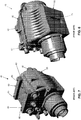
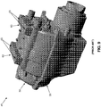
Figs. 4-9 ,X-ray tube assembly 25 is mounted to rotatingdisk assembly 35 using anX-ray tube mount 45. More particularly,X-ray tube mount 45 comprises a housing which is typically formed in two sections, anouter section 50 and aninner section 55, withX-ray tube assembly 25 being captured betweenouter section 50 andinner section 55. As used herein, the terms "outer" and "inner" are characterized in the context of the center of rotation of rotatingdisk assembly 35, i.e.,inner section 55 is disposed closer to the center of rotation of rotatingdisk assembly 35 thanouter section 50. -
Outer section 50 ofX-ray tube mount 45 is secured to rotatingdisk assembly 35, whereby to secure X-ray tube mount 45 (and hence X-ray tube assembly 25) to rotatingdisk assembly 35. More particularly,outer section 50 ofX-ray tube mount 45 comprises twofeet 60 which are secured to rotatingdisk assembly 35 viabolts 63 which extend throughholes 65 infeet 60 and engage drum mounts 66 (e.g., brackets). Thus,holes 65 infeet 60 provide mounting constructs for mountingX-ray tube mount 45 to rotatingdisk assembly 35. Note thatholes 65 andbolts 63 are disposed at the outer end ofX-ray tube mount 45, i.e., near the outer circumference of rotatingdisk assembly 35. Note also that the outermost portion ofouter section 50 ofX-ray tube mount 45 comprises first and secondlateralmost edges 67A, 67B, and that holes 65 (i.e., the mounting constructs) are disposed laterally inboard of first and secondlateralmost edges 67A, 67B. -
Inner section 55 ofX-ray tube mount 45 includes awindow 70 which emits the X-rays fromX-ray tube assembly 25. - In addition to the foregoing, it should also be appreciated that
X-ray tube assembly 25 generally comprises a so-called "moving anode" X-ray tube. In a moving anode X-ray tube, which is commonly used in medical scanners due to the higher energy requirements associated with medical imaging, the anode 71 (Fig. 6 ) of theX-ray tube assembly 25 is mounted on ashaft 72 which is rotated at a high rate of speed (e.g., up to 10,000 revolutions per minute) within the X-ray tube assembly. Thecathode 73 emits electrons which are drawn toanode 71, withX-rays 40 being emitted off the anode and passing outwindow 70. It should be appreciated that in a moving anode X-ray tube,cathode 73 is radially displaced from the axis ofrotation 74 of anode 71 (which axis ofrotation 74 is sometimes referred to as "the longitudinal axis of the X-ray tube"). It should also be appreciated that in a moving anode X-ray tube, delicate bearings must be provided forshaft 72, etc., in order to sustain the high rate of rotation required for the moving anode. - It will be appreciated that any instability in the mounting of
X-ray tube assembly 25 to rotatingdisk assembly 35 can produce variations in the X-ray beam characteristics, and hence can negatively affect the quality of the images generated byCT imaging system 5. In addition, sinceX-ray tube assembly 25 typically contains rapidly moving parts (e.g., an anode rotating at up to 10,000 revolutions per minute), any instability in the mounting ofX-ray tube assembly 25 to rotatingdisk assembly 35 can cause excessive wear of the parts (e.g., bearings) withinX-ray tube assembly 25, which can shorten the life of the X-ray tube assembly. It will be appreciated that, inasmuch as the X-ray tube assembly is a relatively expensive component of a CT imaging system, excessive wear of the parts (e.g., bearings) withinX-ray tube assembly 25 is undesirable. - Historically, the aforementioned X-ray tube mount 45 (comprising
outer section 50 andinner section 55, withouter section 50 comprisingfeet 60 which are secured to rotatingdisk assembly 35 viabolts 63 which extend throughholes 65 infeet 60 and engage drum mounts 66) has performed acceptably. However, interest has now arisen in rotating the rotatingdisk assembly 35 with significantly increased speeds, e.g., at 270 revolutions per minute. At these increased speeds, the forces imposed onX-ray tube assembly 25 andX-ray tube mount 45 are quite large, and the conventionalX-ray tube mount 45 has proven incapable of providing the requisite stability forX-ray tube assembly 25 as rotatingdisk assembly 35 is rotated. Among other things, instability in the mounting ofX-ray tube assembly 25 to rotatingdisk assembly 35 has negatively affected the quality of the images generated byCT imaging system 5 and has caused excessive wear of the parts (e.g., bearings) withinX-ray tube assembly 25, which shortens the life of the X-ray tube assembly. -
US2003/035506 discloses a system and a method for mounting an X-ray tube within a CT scanner. - Therefore, a new and improved X-ray tube mount is needed for mounting the X-ray tube assembly to the rotating disk assembly in a CT imaging system.
- The invention is defined by
claims 1, 8 and 9. The present invention provides a new and improved X-ray tube mount for mounting the X-ray tube assembly to the rotating disk assembly in a CT imaging system. Among other things, this new and improved X-ray tube mount provides significantly increased stability for an X-ray tube assembly, such that the rotating disk assembly can be rotated with significantly increased speeds, e.g., 270 revolutions per minute, while still providing the requisite stability for the X-ray tube assembly. - In one preferred form, there is provided an X-ray tube mount for mounting an X-ray tube assembly to the rotating disk assembly of a CT imaging system, said X-ray tube mount comprising:
- a housing having an inner end and an outer end, wherein said inner end of said housing is located closer to the center of rotation of the rotating disk assembly than said outer end of said housing; and
- at least one mounting construct for mounting said housing to the rotating disk assembly, wherein said at least one mounting construct is disposed intermediate said inner end of said housing and said outer end of said housing.
- In another preferred form, there is provided apparatus comprising:
- an X-ray tube mount for mounting an X-ray tube assembly to the rotating disk assembly of a CT imaging system, said X-ray tube mount comprising:
- a housing having an inner end and an outer end, wherein said inner end of said housing is located closer to the center of rotation of the rotating disk assembly than said outer end of said housing; and
- at least one mounting construct for mounting said housing to the rotating disk assembly, wherein said at least one mounting construct is disposed intermediate said inner end of said housing and said outer end of said housing; and
- an X-ray tube assembly disposed within said housing.
- In another preferred form, there is provided a method for scanning an object, said method comprising:
- providing a computer tomography (CT) imaging system comprising a rotating disk assembly having an axial opening formed therein, an X-ray tube assembly mounted to said rotating disk assembly on one side of said axial opening, and an X-ray detector assembly mounted to said rotating disk assembly on the opposing side of said axial opening, wherein said X-ray tube assembly is mounted to said rotating disk assembly using an X-ray tube mount, wherein said X-ray tube mount comprises:
- a housing having an inner end and an outer end, wherein said inner end of said housing is located closer to the center of rotation of said rotating disk assembly than said outer end of said housing; and
- at least one mounting construct for mounting said housing to said rotating disk assembly, wherein said at least one mounting construct is disposed intermediate said inner end of said housing and said outer end of said housing;
- positioning the object to be scanned within said axial opening of said rotating disk assembly; and
- while rotating said rotating disk assembly, passing X-rays from said X-ray tube assembly through the object and detecting X-rays passing through the object with said X-ray detector.
- These and other objects and features of the present invention will be more fully disclosed or rendered obvious by the following detailed description of the preferred embodiments of the invention, which is to be considered together with the accompanying drawings wherein like numbers refer to like parts, and further wherein:
-
Figs. 1-3 are schematic views showing the general construction of a CT imaging system; -
Figs. 4-9 are schematic views showing a conventional X-ray tube mount for mounting an X-ray tube assembly to the rotating disk assembly of a CT imaging system; -
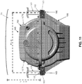
Figs. 10-15 are schematic views showing a new and improved X-ray tube mount formed in accordance with the present invention for mounting an X-ray tube assembly to the rotating disk assembly of a CT imaging system; -
Figs. 16 and 17 are schematic views showing the stiffness of the conventional X-ray tube mount shown inFigs. 4-9 ; and -
Figs. 18 and 19 are schematic views showing the stiffness of the new and improved X-ray tube mount shown inFigs. 10-15 . - The present invention provides a new and improved X-ray tube mount for mounting the X-ray tube assembly to the rotating disk assembly in a CT imaging system. Among other things, this new and improved X-ray tube mount provides significantly increased stability for an X-ray tube assembly, such that the rotating disk assembly can be rotated with significantly increased speeds, e.g., 270 revolutions per minute, while still providing the requisite stability for the X-ray tube assembly.
- More particularly, and looking now at
Figs. 10-15 , there is shown a new and improvedX-ray tube mount 145 for mountingX-ray tube assembly 25 torotating disk assembly 35. The new and improvedX-ray tube mount 145 comprises a housing which is formed in two sections, anouter section 150 and aninner section 155, withX-ray tube assembly 25 being captured to X-raytube mount 145 betweenouter section 150 andinner section 155. Again, as used herein, the terms "outer" and "inner" are characterized in the context of the center of rotation ofrotating disk assembly 35, i.e.,inner section 155 lies closer to the center of rotation ofrotating disk assembly 35 thanouter section 150. -
Inner section 155 is secured torotating disk assembly 35, whereby to secure X-ray tube mount 145 (and hence X-ray tube assembly 25) torotating disk assembly 35. More particularly, with the present invention,inner section 155 ofX-ray tube mount 145 comprises a pair offlanges 160 which extend parallel to the longitudinal axis of X-ray tube assembly 25 (i.e., parallel to the axis ofrotation 74 of anode 71) and are secured torotating disk assembly 35 viabolts 163 which extend throughholes 165 inflanges 160 and engage drum mounts 166 (e.g., brackets). Thus, holes 165 inflanges 160 provide mounting constructs for mountingX-ray tube mount 145 torotating disk assembly 35. Note that the outermost portion ofouter section 150 ofX-ray tube mount 145 comprises first and second lateralmost edges 167A, 167B, and thatholes 165 inflanges 160 of inner section 155 (i.e., the mounting constructs) are disposed laterally outboard of first and second lateralmost edges 167A, 167B. - Significantly, holes 165 in
flanges 160 of the new and improvedX-ray tube mount 145 are disposed outboard ofholes 65 infeet 60 of conventional X-ray tube mount 45 (note the distance X inFigs. 4 and5 versus the distance X+α inFigs. 10 and11 ), and holes 165 inflanges 160 of improvedX-ray tube mount 145 are disposed closer to the center of rotation ofrotating disk assembly 35 thanholes 65 infeet 60 of conventional X-ray tube mount 45 (note the distance Y inFigs. 4 and5 versus the distance Y+β inFigs. 10 and11 ), whereby to provide significantly increased stability forX-ray tube assembly 25. - Furthermore, holes 165 in
flanges 160 of improvedX-ray tube mount 145 are set on a line which extends parallel to the longitudinal axis of X-ray tube assembly 25 (i.e., parallel to the axis ofrotation 74 ofanode 71 of X-ray tube assembly 25), which results in significantly increased stability forX-ray tube assembly 145 asrotating disk assembly 35 is rotated. - Thus it will be seen that with the present invention, (i) the mounting constructs of the new and improved
X-ray tube mount 145 are moved laterally outward and radially inward relative to the mounting constructs of conventional X-ray tube mount 45 (see the distance X+α inFigs. 10 and11 versus the distance X inFigs. 4 and5 , and see the distance Y+β inFigs. 10 and11 versus the distance Y inFigs. 4 and5 ), and (ii) the mounting constructs of the new and improvedX-ray tube mount 145 are set on a line which extends parallel to the longitudinal axis of X-ray tube assembly 25 (i.e., parallel to the axis ofrotation 74 ofanode 71 of X-ray tube assembly 25), whereby to provide significantly more stability forX-ray tube assembly 25 asrotating disk assembly 35 ofCT imaging system 5 is rotated. -
Inner section 155 ofX-ray tube mount 145 also includes awindow 170 which emits the X-rays fromX-ray tube assembly 25. - The new and improved
X-ray tube mount 145 provides significantly more stability forX-ray tube assembly 25 than does conventionalX-ray tube mount 45. See, for example,Figs. 16 and 17 , which show the extent of deformation of conventionalX-ray tube mount 45, andFigs. 18 and 19 , which show the extent of deformation with the improvedX-ray tube mount 145. As can be seen fromFigs. 16 and 17 , and18 and 19 , the new and improvedX-ray tube mount 145 provides significantly more stability forX-ray tube assembly 25 than does conventionalX-ray tube mount 45. - It should also be appreciated that, if desired,
flanges 160 may be formed onouter section 150 ofX-ray tube mount 145, rather than being formed oninner section 155 ofX-ray tube mount 145 as disclosed above. Of course, in this alternative construction,flanges 160 would be formed on the inner end ofouter section 150 ofX-ray tube mount 145, rather than being formed on the outer end ofinner section 155 ofX-ray tube mount 145 as previously disclosed. - It should also be appreciated that, if desired, improved
X-ray tube mount 145 can also provide additional mounting means at the outermost surfaces of itsouter section 150. - It should be understood that many additional changes in the details, materials, steps and arrangements of parts, which have been herein described and illustrated in order to explain the nature of the present invention, may be made by those skilled in the art while still remaining within the principles and scope of the invention.
Claims (9)
- An X-ray tube mount (145) for mounting an X-ray tube assembly (25) to a rotating disk assembly (35) of a CT imaging system (5), wherein the X-ray tube assembly (25) comprises an anode (71) rotating on a shaft (72), the shaft (72) having a longitudinal axis (74) extending therethrough, said X-ray tube mount (145) comprising:a housing for receiving the x-ray tube assembly (25), the housing having an inner end and an outer end, wherein said inner end of said housing is located closer to the center of rotation of the rotating disk assembly (35) than said outer end of said housing; andat least two mounting constructs (165) for mounting said housing to the rotating disk assembly (35), the at least two mounting constructs (165) being connected to said housing at two points, wherein the two points are co-planar with the longitudinal axis (74) of the shaft (72) when said X-ray tube assembly (25) is disposed in said housing.
- An X-ray tube mount (145) according to claim 1
wherein said at least two mounting constructs (165) comprise a hole. - An X-ray tube mount (145) according to claim 1
wherein the outer end of said housing terminates in first and second lateralmost edges (167A, 167B), and further wherein said at least two mounting constructs (165) are disposed more lateral than said first and second lateralmost edges (167A, 167B) of said outer end of said housing. - An X-ray tube mount (145) according to claim 1
wherein said housing comprises an outer section (150) terminating in said outer end and an inner section (155) terminating in said inner end. - An X-ray tube mount (145) according to claim 4
wherein said housing comprises at least one axially-extending flange (160), wherein said at least one axially-extending flange (160) is formed on one of an inner portion of said outer section (150) and an outer portion of said inner section (155), and further wherein one of said at least two mounting constructs (165) is disposed on said at least one axially-extending flange (160). - An X-ray tube mount (145) according to claim 5
wherein said at least one axially-extending flange (160) is formed on said outer portion of said inner section (155). - An X-ray tube mount (145) according to claim 5
wherein said housing comprises at least two axially-extending flanges (160), and further wherein at least one mounting construct (165) is mounted to each axially-extending flange (160). - Apparatus comprising:
an X-ray tube mount (145) for mounting an X-ray tube assembly (25) to a rotating disk assembly (35) of a CT imaging system (5), wherein the X-ray tube assembly (25) comprises an anode (71) rotating on a shaft (72), the shaft (72) having a longitudinal axis (74) extending therethrough, said X-ray tube mount (145) comprising:a housing for receiving the x-ray tube assembly (25), the housing having an inner end and an outer end, wherein said inner end of said housing is located closer to the center of rotation of the rotating disk assembly (35) than said outer end of said housing; andat least two mounting constructs (165) for mounting said housing to the rotating disk assembly (35), the at least two mounting constructs (165) being connected to said housing at two points, wherein the two points are coplanar with the longitudinal axis (74) of the shaft (72); wherein the apparatus comprises said X-ray tube assembly (25) disposed within said housing. - A method for scanning an object, said method comprising:providing a computer tomography (CT) imaging system (5) comprising a rotating disk assembly (35) having an axial opening (20) formed therein, an X-ray tube assembly (25) mounted to said rotating disk assembly (35) on one side of said axial opening (20), and an X-ray detector assembly (30) mounted to said rotating disk assembly (35) on the opposing side of said axial opening (20), wherein said X-ray tube assembly (25) comprises an anode (71) rotating on a shaft (72), the shaft (72) having a longitudinal axis (74) extending therethrough, wherein said X-ray tube assembly (25) is mounted to said rotating disk assembly (35) using an X-ray tube mount (145), wherein said X-ray tube mount (145) comprises:a housing for receiving the x-ray tube assembly (25) such that said X-ray tube assembly (25) is disposed within said housing, the housing having an inner end and an outer end, wherein said inner end of said housing is located closer to the center of rotation of said rotating disk assembly (35) than said outer end of said housing; andat least two mounting constructs (165) for mounting said housing to said rotating disk assembly (35), the at least two mounting constructs (165) being connected to said housing at two points, wherein the two points are coplanar with the longitudinal axis (74) of the shaft (72);positioning the object to be scanned within said axial opening (20) of said rotating disk assembly (35); andwhile rotating said rotating disk assembly (35), passing X-rays from said X-ray tube assembly (25) through the object and detecting X-rays passing through the object with said X-ray detector assembly (30).
Applications Claiming Priority (2)
| Application Number | Priority Date | Filing Date | Title |
|---|---|---|---|
| US201361809917P | 2013-04-09 | 2013-04-09 | |
| PCT/US2014/033537 WO2014169059A1 (en) | 2013-04-09 | 2014-04-09 | Computerized tomography (ct) imaging system with improved x-ray tube mount |
Publications (3)
| Publication Number | Publication Date |
|---|---|
| EP2983590A1 EP2983590A1 (en) | 2016-02-17 |
| EP2983590A4 EP2983590A4 (en) | 2017-04-19 |
| EP2983590B1 true EP2983590B1 (en) | 2020-09-02 |
Family
ID=51654471
Family Applications (1)
| Application Number | Title | Priority Date | Filing Date |
|---|---|---|---|
| EP14782465.0A Not-in-force EP2983590B1 (en) | 2013-04-09 | 2014-04-09 | Computerized tomography (ct) imaging system with improved x-ray tube mount |
Country Status (3)
| Country | Link |
|---|---|
| US (1) | US9363876B2 (en) |
| EP (1) | EP2983590B1 (en) |
| WO (1) | WO2014169059A1 (en) |
Families Citing this family (2)
| Publication number | Priority date | Publication date | Assignee | Title |
|---|---|---|---|---|
| US9204850B2 (en) * | 2014-02-04 | 2015-12-08 | General Electric Company | Gantry with secondary safety mechanism |
| CN111419259B (en) * | 2020-04-01 | 2023-05-02 | 上海大骋医疗科技有限公司 | Mechanism suitable for installation and adjustment of X-ray tube of CT equipment |
Family Cites Families (8)
| Publication number | Priority date | Publication date | Assignee | Title |
|---|---|---|---|---|
| US4115695A (en) * | 1977-02-25 | 1978-09-19 | General Electric Company | Gantry for computed tomography |
| US4366577A (en) | 1981-07-13 | 1982-12-28 | General Electric Company | Computed tomography system cable retractor |
| US4658408A (en) | 1985-03-04 | 1987-04-14 | Picker International Inc. | Computed tomography brake method and apparatus |
| US6519312B1 (en) * | 2000-08-16 | 2003-02-11 | Analogic Corporation | System and method for mounting x-ray tube in CT scanner |
| US6590953B2 (en) * | 2000-09-12 | 2003-07-08 | Hitachi Medical Corporation | X-ray CT scanner |
| US7568836B2 (en) * | 2004-07-30 | 2009-08-04 | Neurologica Corp. | Mobile computerized tomography (CT) imaging system with off-center x-ray beam |
| US7281848B2 (en) * | 2005-08-17 | 2007-10-16 | General Electric Co. | X-ray tube mounting methodology |
| US8340250B2 (en) * | 2009-09-04 | 2012-12-25 | General Electric Company | System and method for generating X-rays |
-
2014
- 2014-04-09 EP EP14782465.0A patent/EP2983590B1/en not_active Not-in-force
- 2014-04-09 US US14/249,106 patent/US9363876B2/en active Active
- 2014-04-09 WO PCT/US2014/033537 patent/WO2014169059A1/en not_active Ceased
Non-Patent Citations (1)
| Title |
|---|
| None * |
Also Published As
| Publication number | Publication date |
|---|---|
| US9363876B2 (en) | 2016-06-07 |
| EP2983590A1 (en) | 2016-02-17 |
| US20140301526A1 (en) | 2014-10-09 |
| WO2014169059A1 (en) | 2014-10-16 |
| EP2983590A4 (en) | 2017-04-19 |
Similar Documents
| Publication | Publication Date | Title |
|---|---|---|
| JP5265906B2 (en) | Convection cooled X-ray tube target and manufacturing method thereof | |
| US9254108B2 (en) | Gantry with bore safety mechanism | |
| US8681930B2 (en) | High speed rotating gantry | |
| CN105431086B (en) | System and method for integrating pet detector and CT scan frame | |
| JP5809806B2 (en) | X-ray device with wide coverage | |
| US20080260102A1 (en) | X-ray tube target brazed emission layer | |
| US7558375B2 (en) | Stationary cathode in rotating frame x-ray tube | |
| US7927013B2 (en) | Computed tomography rotor, and gantry embodying same | |
| US20110150174A1 (en) | Multiple x-ray tube system and method of making same | |
| US20210353237A1 (en) | Rotating structure for radiation imaging modalities | |
| US9363876B2 (en) | Computerized tomography (CT) imaging system with improved X-ray tube mount | |
| CN107810538A (en) | System for generating and collimating X-ray beams | |
| JP5674299B2 (en) | Apparatus and method for Z-position dependent X-ray beam filtering of an imaging system | |
| US6762540B2 (en) | One-piece tab assembly for a cathode cup of an X-ray imaging machine | |
| US20110135065A1 (en) | Magnetic coupler drive for x-ray tube anode rotation | |
| EP3582690B1 (en) | Anti-scatter collimator for radiation imaging modalities | |
| US7974377B2 (en) | X-ray detection methods and apparatus | |
| US20080063145A1 (en) | Apparatus and method for rapidly switching the energy spectrum of diagnostic X-ray beams | |
| US20100027758A1 (en) | Computed tomography rotor rigidified by a metal matrix material | |
| US20140362969A1 (en) | System and method for mounting x-ray tube on a ct gantry for high g-load applications | |
| DE102013101231A1 (en) | X-ray tube for attachment to gantry of e.g. computed tomography system that is utilized for recognizing explosive parcel, has wear-resistant coating attached to two materials and positioned between two materials | |
| US20180076000A1 (en) | X-ray back scattering for inspection of part | |
| EP2994050B1 (en) | Imaging system rotating component alignment with iso-center | |
| EP4413925A1 (en) | Ct imaging system | |
| EP4358113A2 (en) | System and method for creating a vacuum in an x-ray tube |
Legal Events
| Date | Code | Title | Description |
|---|---|---|---|
| PUAI | Public reference made under article 153(3) epc to a published international application that has entered the european phase |
Free format text: ORIGINAL CODE: 0009012 |
|
| 17P | Request for examination filed |
Effective date: 20151109 |
|
| AK | Designated contracting states |
Kind code of ref document: A1 Designated state(s): AL AT BE BG CH CY CZ DE DK EE ES FI FR GB GR HR HU IE IS IT LI LT LU LV MC MK MT NL NO PL PT RO RS SE SI SK SM TR |
|
| AX | Request for extension of the european patent |
Extension state: BA ME |
|
| DAX | Request for extension of the european patent (deleted) | ||
| A4 | Supplementary search report drawn up and despatched |
Effective date: 20170322 |
|
| RIC1 | Information provided on ipc code assigned before grant |
Ipc: A61B 6/03 20060101AFI20170316BHEP |
|
| STAA | Information on the status of an ep patent application or granted ep patent |
Free format text: STATUS: EXAMINATION IS IN PROGRESS |
|
| 17Q | First examination report despatched |
Effective date: 20200402 |
|
| GRAP | Despatch of communication of intention to grant a patent |
Free format text: ORIGINAL CODE: EPIDOSNIGR1 |
|
| STAA | Information on the status of an ep patent application or granted ep patent |
Free format text: STATUS: GRANT OF PATENT IS INTENDED |
|
| RIC1 | Information provided on ipc code assigned before grant |
Ipc: G01N 23/046 20180101ALN20200505BHEP Ipc: A61B 6/00 20060101ALI20200505BHEP Ipc: A61B 6/03 20060101AFI20200505BHEP Ipc: H05G 1/04 20060101ALI20200505BHEP |
|
| INTG | Intention to grant announced |
Effective date: 20200520 |
|
| GRAS | Grant fee paid |
Free format text: ORIGINAL CODE: EPIDOSNIGR3 |
|
| GRAA | (expected) grant |
Free format text: ORIGINAL CODE: 0009210 |
|
| STAA | Information on the status of an ep patent application or granted ep patent |
Free format text: STATUS: THE PATENT HAS BEEN GRANTED |
|
| AK | Designated contracting states |
Kind code of ref document: B1 Designated state(s): AL AT BE BG CH CY CZ DE DK EE ES FI FR GB GR HR HU IE IS IT LI LT LU LV MC MK MT NL NO PL PT RO RS SE SI SK SM TR |
|
| REG | Reference to a national code |
Ref country code: GB Ref legal event code: FG4D |
|
| REG | Reference to a national code |
Ref country code: AT Ref legal event code: REF Ref document number: 1307863 Country of ref document: AT Kind code of ref document: T Effective date: 20200915 Ref country code: CH Ref legal event code: EP |
|
| REG | Reference to a national code |
Ref country code: DE Ref legal event code: R096 Ref document number: 602014069734 Country of ref document: DE |
|
| REG | Reference to a national code |
Ref country code: IE Ref legal event code: FG4D |
|
| REG | Reference to a national code |
Ref country code: NL Ref legal event code: FP |
|
| REG | Reference to a national code |
Ref country code: LT Ref legal event code: MG4D |
|
| PG25 | Lapsed in a contracting state [announced via postgrant information from national office to epo] |
Ref country code: FI Free format text: LAPSE BECAUSE OF FAILURE TO SUBMIT A TRANSLATION OF THE DESCRIPTION OR TO PAY THE FEE WITHIN THE PRESCRIBED TIME-LIMIT Effective date: 20200902 Ref country code: GR Free format text: LAPSE BECAUSE OF FAILURE TO SUBMIT A TRANSLATION OF THE DESCRIPTION OR TO PAY THE FEE WITHIN THE PRESCRIBED TIME-LIMIT Effective date: 20201203 Ref country code: NO Free format text: LAPSE BECAUSE OF FAILURE TO SUBMIT A TRANSLATION OF THE DESCRIPTION OR TO PAY THE FEE WITHIN THE PRESCRIBED TIME-LIMIT Effective date: 20201202 Ref country code: SE Free format text: LAPSE BECAUSE OF FAILURE TO SUBMIT A TRANSLATION OF THE DESCRIPTION OR TO PAY THE FEE WITHIN THE PRESCRIBED TIME-LIMIT Effective date: 20200902 Ref country code: BG Free format text: LAPSE BECAUSE OF FAILURE TO SUBMIT A TRANSLATION OF THE DESCRIPTION OR TO PAY THE FEE WITHIN THE PRESCRIBED TIME-LIMIT Effective date: 20201202 Ref country code: LT Free format text: LAPSE BECAUSE OF FAILURE TO SUBMIT A TRANSLATION OF THE DESCRIPTION OR TO PAY THE FEE WITHIN THE PRESCRIBED TIME-LIMIT Effective date: 20200902 Ref country code: HR Free format text: LAPSE BECAUSE OF FAILURE TO SUBMIT A TRANSLATION OF THE DESCRIPTION OR TO PAY THE FEE WITHIN THE PRESCRIBED TIME-LIMIT Effective date: 20200902 |
|
| REG | Reference to a national code |
Ref country code: AT Ref legal event code: MK05 Ref document number: 1307863 Country of ref document: AT Kind code of ref document: T Effective date: 20200902 |
|
| PG25 | Lapsed in a contracting state [announced via postgrant information from national office to epo] |
Ref country code: PL Free format text: LAPSE BECAUSE OF FAILURE TO SUBMIT A TRANSLATION OF THE DESCRIPTION OR TO PAY THE FEE WITHIN THE PRESCRIBED TIME-LIMIT Effective date: 20200902 Ref country code: RS Free format text: LAPSE BECAUSE OF FAILURE TO SUBMIT A TRANSLATION OF THE DESCRIPTION OR TO PAY THE FEE WITHIN THE PRESCRIBED TIME-LIMIT Effective date: 20200902 Ref country code: LV Free format text: LAPSE BECAUSE OF FAILURE TO SUBMIT A TRANSLATION OF THE DESCRIPTION OR TO PAY THE FEE WITHIN THE PRESCRIBED TIME-LIMIT Effective date: 20200902 |
|
| PG25 | Lapsed in a contracting state [announced via postgrant information from national office to epo] |
Ref country code: CZ Free format text: LAPSE BECAUSE OF FAILURE TO SUBMIT A TRANSLATION OF THE DESCRIPTION OR TO PAY THE FEE WITHIN THE PRESCRIBED TIME-LIMIT Effective date: 20200902 Ref country code: EE Free format text: LAPSE BECAUSE OF FAILURE TO SUBMIT A TRANSLATION OF THE DESCRIPTION OR TO PAY THE FEE WITHIN THE PRESCRIBED TIME-LIMIT Effective date: 20200902 Ref country code: RO Free format text: LAPSE BECAUSE OF FAILURE TO SUBMIT A TRANSLATION OF THE DESCRIPTION OR TO PAY THE FEE WITHIN THE PRESCRIBED TIME-LIMIT Effective date: 20200902 Ref country code: SM Free format text: LAPSE BECAUSE OF FAILURE TO SUBMIT A TRANSLATION OF THE DESCRIPTION OR TO PAY THE FEE WITHIN THE PRESCRIBED TIME-LIMIT Effective date: 20200902 Ref country code: PT Free format text: LAPSE BECAUSE OF FAILURE TO SUBMIT A TRANSLATION OF THE DESCRIPTION OR TO PAY THE FEE WITHIN THE PRESCRIBED TIME-LIMIT Effective date: 20210104 |
|
| PG25 | Lapsed in a contracting state [announced via postgrant information from national office to epo] |
Ref country code: ES Free format text: LAPSE BECAUSE OF FAILURE TO SUBMIT A TRANSLATION OF THE DESCRIPTION OR TO PAY THE FEE WITHIN THE PRESCRIBED TIME-LIMIT Effective date: 20200902 Ref country code: AL Free format text: LAPSE BECAUSE OF FAILURE TO SUBMIT A TRANSLATION OF THE DESCRIPTION OR TO PAY THE FEE WITHIN THE PRESCRIBED TIME-LIMIT Effective date: 20200902 Ref country code: AT Free format text: LAPSE BECAUSE OF FAILURE TO SUBMIT A TRANSLATION OF THE DESCRIPTION OR TO PAY THE FEE WITHIN THE PRESCRIBED TIME-LIMIT Effective date: 20200902 Ref country code: IS Free format text: LAPSE BECAUSE OF FAILURE TO SUBMIT A TRANSLATION OF THE DESCRIPTION OR TO PAY THE FEE WITHIN THE PRESCRIBED TIME-LIMIT Effective date: 20210102 |
|
| REG | Reference to a national code |
Ref country code: DE Ref legal event code: R097 Ref document number: 602014069734 Country of ref document: DE |
|
| PG25 | Lapsed in a contracting state [announced via postgrant information from national office to epo] |
Ref country code: SK Free format text: LAPSE BECAUSE OF FAILURE TO SUBMIT A TRANSLATION OF THE DESCRIPTION OR TO PAY THE FEE WITHIN THE PRESCRIBED TIME-LIMIT Effective date: 20200902 |
|
| PLBE | No opposition filed within time limit |
Free format text: ORIGINAL CODE: 0009261 |
|
| STAA | Information on the status of an ep patent application or granted ep patent |
Free format text: STATUS: NO OPPOSITION FILED WITHIN TIME LIMIT |
|
| PGFP | Annual fee paid to national office [announced via postgrant information from national office to epo] |
Ref country code: DE Payment date: 20210531 Year of fee payment: 8 |
|
| 26N | No opposition filed |
Effective date: 20210603 |
|
| PG25 | Lapsed in a contracting state [announced via postgrant information from national office to epo] |
Ref country code: SI Free format text: LAPSE BECAUSE OF FAILURE TO SUBMIT A TRANSLATION OF THE DESCRIPTION OR TO PAY THE FEE WITHIN THE PRESCRIBED TIME-LIMIT Effective date: 20200902 Ref country code: DK Free format text: LAPSE BECAUSE OF FAILURE TO SUBMIT A TRANSLATION OF THE DESCRIPTION OR TO PAY THE FEE WITHIN THE PRESCRIBED TIME-LIMIT Effective date: 20200902 |
|
| PG25 | Lapsed in a contracting state [announced via postgrant information from national office to epo] |
Ref country code: IT Free format text: LAPSE BECAUSE OF FAILURE TO SUBMIT A TRANSLATION OF THE DESCRIPTION OR TO PAY THE FEE WITHIN THE PRESCRIBED TIME-LIMIT Effective date: 20200902 |
|
| PGFP | Annual fee paid to national office [announced via postgrant information from national office to epo] |
Ref country code: NL Payment date: 20210421 Year of fee payment: 8 |
|
| PG25 | Lapsed in a contracting state [announced via postgrant information from national office to epo] |
Ref country code: MC Free format text: LAPSE BECAUSE OF FAILURE TO SUBMIT A TRANSLATION OF THE DESCRIPTION OR TO PAY THE FEE WITHIN THE PRESCRIBED TIME-LIMIT Effective date: 20200902 |
|
| GBPC | Gb: european patent ceased through non-payment of renewal fee |
Effective date: 20210409 |
|
| PG25 | Lapsed in a contracting state [announced via postgrant information from national office to epo] |
Ref country code: LU Free format text: LAPSE BECAUSE OF NON-PAYMENT OF DUE FEES Effective date: 20210409 |
|
| REG | Reference to a national code |
Ref country code: BE Ref legal event code: MM Effective date: 20210430 |
|
| PG25 | Lapsed in a contracting state [announced via postgrant information from national office to epo] |
Ref country code: LI Free format text: LAPSE BECAUSE OF NON-PAYMENT OF DUE FEES Effective date: 20210430 Ref country code: CH Free format text: LAPSE BECAUSE OF NON-PAYMENT OF DUE FEES Effective date: 20210430 Ref country code: GB Free format text: LAPSE BECAUSE OF NON-PAYMENT OF DUE FEES Effective date: 20210409 Ref country code: FR Free format text: LAPSE BECAUSE OF NON-PAYMENT OF DUE FEES Effective date: 20210430 |
|
| REG | Reference to a national code |
Ref country code: DE Ref legal event code: R082 Ref document number: 602014069734 Country of ref document: DE Representative=s name: GEITZ TRUCKENMUELLER LUCHT CHRIST PATENTANWAEL, DE Ref country code: DE Ref legal event code: R082 Ref document number: 602014069734 Country of ref document: DE Representative=s name: GEITZ PATENTANWAELTE PARTG MBB, DE |
|
| PG25 | Lapsed in a contracting state [announced via postgrant information from national office to epo] |
Ref country code: IE Free format text: LAPSE BECAUSE OF NON-PAYMENT OF DUE FEES Effective date: 20210409 |
|
| PG25 | Lapsed in a contracting state [announced via postgrant information from national office to epo] |
Ref country code: IS Free format text: LAPSE BECAUSE OF FAILURE TO SUBMIT A TRANSLATION OF THE DESCRIPTION OR TO PAY THE FEE WITHIN THE PRESCRIBED TIME-LIMIT Effective date: 20210102 |
|
| PG25 | Lapsed in a contracting state [announced via postgrant information from national office to epo] |
Ref country code: BE Free format text: LAPSE BECAUSE OF NON-PAYMENT OF DUE FEES Effective date: 20210430 |
|
| REG | Reference to a national code |
Ref country code: DE Ref legal event code: R119 Ref document number: 602014069734 Country of ref document: DE |
|
| REG | Reference to a national code |
Ref country code: NL Ref legal event code: MM Effective date: 20220501 |
|
| PG25 | Lapsed in a contracting state [announced via postgrant information from national office to epo] |
Ref country code: NL Free format text: LAPSE BECAUSE OF NON-PAYMENT OF DUE FEES Effective date: 20220501 Ref country code: DE Free format text: LAPSE BECAUSE OF NON-PAYMENT OF DUE FEES Effective date: 20221103 |
|
| PG25 | Lapsed in a contracting state [announced via postgrant information from national office to epo] |
Ref country code: HU Free format text: LAPSE BECAUSE OF FAILURE TO SUBMIT A TRANSLATION OF THE DESCRIPTION OR TO PAY THE FEE WITHIN THE PRESCRIBED TIME-LIMIT; INVALID AB INITIO Effective date: 20140409 |
|
| PG25 | Lapsed in a contracting state [announced via postgrant information from national office to epo] |
Ref country code: CY Free format text: LAPSE BECAUSE OF FAILURE TO SUBMIT A TRANSLATION OF THE DESCRIPTION OR TO PAY THE FEE WITHIN THE PRESCRIBED TIME-LIMIT Effective date: 20200902 |
|
| PG25 | Lapsed in a contracting state [announced via postgrant information from national office to epo] |
Ref country code: MK Free format text: LAPSE BECAUSE OF FAILURE TO SUBMIT A TRANSLATION OF THE DESCRIPTION OR TO PAY THE FEE WITHIN THE PRESCRIBED TIME-LIMIT Effective date: 20200902 |
|
| PG25 | Lapsed in a contracting state [announced via postgrant information from national office to epo] |
Ref country code: TR Free format text: LAPSE BECAUSE OF FAILURE TO SUBMIT A TRANSLATION OF THE DESCRIPTION OR TO PAY THE FEE WITHIN THE PRESCRIBED TIME-LIMIT Effective date: 20200902 |
|
| PG25 | Lapsed in a contracting state [announced via postgrant information from national office to epo] |
Ref country code: MT Free format text: LAPSE BECAUSE OF FAILURE TO SUBMIT A TRANSLATION OF THE DESCRIPTION OR TO PAY THE FEE WITHIN THE PRESCRIBED TIME-LIMIT Effective date: 20200902 |