EP2983455A1 - Tubular choked waveguide applicator - Google Patents
Tubular choked waveguide applicator Download PDFInfo
- Publication number
- EP2983455A1 EP2983455A1 EP15179898.0A EP15179898A EP2983455A1 EP 2983455 A1 EP2983455 A1 EP 2983455A1 EP 15179898 A EP15179898 A EP 15179898A EP 2983455 A1 EP2983455 A1 EP 2983455A1
- Authority
- EP
- European Patent Office
- Prior art keywords
- microwave
- tubular waveguide
- waveguide applicator
- resistive
- applicator
- Prior art date
- Legal status (The legal status is an assumption and is not a legal conclusion. Google has not performed a legal analysis and makes no representation as to the accuracy of the status listed.)
- Granted
Links
Images


Classifications
-
- H—ELECTRICITY
- H05—ELECTRIC TECHNIQUES NOT OTHERWISE PROVIDED FOR
- H05B—ELECTRIC HEATING; ELECTRIC LIGHT SOURCES NOT OTHERWISE PROVIDED FOR; CIRCUIT ARRANGEMENTS FOR ELECTRIC LIGHT SOURCES, IN GENERAL
- H05B6/00—Heating by electric, magnetic or electromagnetic fields
- H05B6/64—Heating using microwaves
- H05B6/70—Feed lines
- H05B6/707—Feed lines using waveguides
-
- H—ELECTRICITY
- H05—ELECTRIC TECHNIQUES NOT OTHERWISE PROVIDED FOR
- H05B—ELECTRIC HEATING; ELECTRIC LIGHT SOURCES NOT OTHERWISE PROVIDED FOR; CIRCUIT ARRANGEMENTS FOR ELECTRIC LIGHT SOURCES, IN GENERAL
- H05B6/00—Heating by electric, magnetic or electromagnetic fields
- H05B6/64—Heating using microwaves
- H05B6/70—Feed lines
- H05B6/701—Feed lines using microwave applicators
-
- H—ELECTRICITY
- H05—ELECTRIC TECHNIQUES NOT OTHERWISE PROVIDED FOR
- H05B—ELECTRIC HEATING; ELECTRIC LIGHT SOURCES NOT OTHERWISE PROVIDED FOR; CIRCUIT ARRANGEMENTS FOR ELECTRIC LIGHT SOURCES, IN GENERAL
- H05B6/00—Heating by electric, magnetic or electromagnetic fields
- H05B6/64—Heating using microwaves
- H05B6/76—Prevention of microwave leakage, e.g. door sealings
-
- H—ELECTRICITY
- H05—ELECTRIC TECHNIQUES NOT OTHERWISE PROVIDED FOR
- H05B—ELECTRIC HEATING; ELECTRIC LIGHT SOURCES NOT OTHERWISE PROVIDED FOR; CIRCUIT ARRANGEMENTS FOR ELECTRIC LIGHT SOURCES, IN GENERAL
- H05B2206/00—Aspects relating to heating by electric, magnetic, or electromagnetic fields covered by group H05B6/00
- H05B2206/04—Heating using microwaves
- H05B2206/046—Microwave drying of wood, ink, food, ceramic, sintering of ceramic, clothes, hair
Definitions
- the invention relates generally to microwave heating apparatus and more particularly to waveguide applicators for heating or drying products with microwaves.
- Microwaves are often used in industrial processes to heat or dry products.
- U.S. Patent No. 4,497,759 describes a waveguide system for dielectrically heating a crystalline polymer drawn into a rod fed continuously through a circular waveguide applicator along its centerline.
- the TM 01 mode is used to concentrate the heating along the centerline.
- the narrow waveguide applicator has an inner diameter of 95.6 mm, which limits its use to small-diameter products, such as drawn polymer rods.
- openings are provided at opposite ends of the applicator for product entry and exit. But microwave radiation can also leak through the openings, especially if the openings are large to accommodate large-diameter products.
- One version of a microwave heating apparatus embodying features of the invention comprises a tubular waveguide applicator forming a heating chamber between a first end and an opposite second end.
- the applicator has a circular cross section and an axis along its centerline.
- a waveguide feed connected between a microwave source and the tubular waveguide applicator at the first end propagates microwaves through the tubular waveguide applicator from the first end to the second end with a dominant TE 01 field pattern in the heating chamber.
- a first resistive choke is connected in series with the tubular waveguide applicator at the first end.
- a second resistive choke is connected in series the tubular waveguide applicator at the second end.
- Each of the resistive chokes includes a plurality of conductive vanes covered with a microwave-absorbent material and spaced apart along the axis in a chevron pattern.
- the vanes have central apertures aligned with openings in the opposite ends of the resistive chokes and with the heating chamber to guide articles to be treated in the heating chamber through the resistive chokes.
- a microwave heating apparatus comprises a tubular waveguide applicator that has a cylindrical outer wall terminating in a first end and an opposite second end to form a heating chamber with a circular cross section between the first and second ends with an axis along the heating chamber's centerline.
- a microwave source supplies microwave energy into the tubular waveguide applicator.
- a first reactive choke is disposed in series with the tubular waveguide applicator at the first end of the tubular waveguide applicator.
- a second reactive choke is disposed in series with the tubular waveguide applicator at the second end of the tubular waveguide applicator.
- a first resistive choke is connected in series with the tubular waveguide applicator and the first reactive choke.
- a second resistive choke is connected in series with the tubular waveguide applicator and the second reactive choke.
- FIGS. 1 and 2 A microwave heating apparatus embodying features of the invention, including a tubular waveguide applicator, is shown in FIGS. 1 and 2 .
- the applicator 10 shown in this example is constructed of a single circular waveguide section having a cylindrical outer wall 11 forming a heating chamber. But the applicator could be constructed of a series of individual circular waveguide sections connected end to end.
- the applicator 10 has circular flanges 12 at each end.
- Plastic or teflon ribs 14 extend radially inward from the inside surface of the metal waveguide walls.
- the ribs 14, which extend along the length of the applicator 10, are spaced apart circumferentially around the inner circumference of the applicator.
- the plastic or teflon ribs 14 are transparent to microwaves.
- the ribs extend radially inward a distance sufficient to bound a central bore 16 through the heating chamber through which articles, such as individual cylindrical items or a continuous cylindrical strand, can pass.
- a microwave source 17 injects microwaves 18, for example, at 915 MHz or 2540 MHz, into the waveguide applicator 10 through a rectangular waveguide feed 20 at an entrance end 22 of the applicator.
- the microwaves propagate along the waveguide applicator 10 from the entrance end 22 to an exit end 23.
- the microwaves travel through the interior of the applicator 10 in a direction of propagation 24 parallel to the axis 25 of the applicator.
- Microwave energy unabsorbed by the articles to be treated in the heating chamber exits the exit end 23 through a rectangular waveguide segment 21 to a dummy load 26, which prevents reflections back into the applicator.
- the TE 01 mode produces an electric field with circular symmetry in the applicator 10 and with its maximum electric-field intensity midway between the centerline and the cylindrical outer wall 11 of the applicator.
- This increased field intensity between the center and the wall is indicated by the bolder and denser arrows 28 concentrically circling the centerline in the electric-field pattern shown in FIG. 5 .
- the magnitude of the electric field at any position along the applicator varies sinusoidally with the passing traveling microwave with reversals of direction every half cycle. Because the field intensity is greatest near the inner ends 30 of the guide ribs 14, the applicator 10 is especially useful in applications that require the outer circumference of the cylindrical article to be heated.
- cylindrical articles 32 enter the vertically oriented applicator 10 at the upper end and fall through the applicator aided by gravity.
- the articles 32 advance through the applicator 10 in or opposite to the direction of propagation 24 of the microwaves.
- the articles could be advanced through the applicator by an injected air stream instead of or in addition to gravity.
- the microwaves heat the outer portions.
- the central bore has to be relatively large with respect to the cross-sectional dimensions of the waveguide applicator 10. For that reason leakage of microwave energy through the large openings at the ends 22, 23 of the applicator is reduced by two chokes 34, 42 at each end.
- the chokes 34 closer to the applicator are reactive chokes that reflect microwave energy back into the applicator.
- the reactive chokes 34 are positioned at the ends 22, 23 of the applicator 10.
- the reactive chokes 34 shown in FIG. 3 in more detail are constructed of four metal circular waveguide segments 36, 37A, 37B, 38. Each segment has a flange 40 at each end to attach to the flange of another segment, of the applicator 10, or of a choke box 42 ( FIG. 1 ) with screws, for example.
- the left-most segment 38 in FIG. 3 is a flanged cylindrical metallic tube having a circular bore.
- the identical interior metallic waveguide segments 37A, 37B are flanged at each end and have a stepped bore formed by a small-diameter section 44 and a large-diameter section 45.
- the small-diameter section 44 has the same inner diameter as the left-most segment 38.
- the right-most segment 36 is the same as the interior segments 37A, 37B, except that the small-diameter section 44' is elongated.
- a plastic or teflon microwave-transparent ring 46 having the same inner diameter as the small-diameter sections 44, 44' is retained in the large-diameter end of each interior waveguide segment 37A, 37B and the right-most segment 36.
- the rings 46 are clamped in place and form a continuous smooth bore with the small-diameter sections 44, 44' and the bore of the left-most segment 38.
- the smooth bore allows cylindrical articles to pass through without snagging.
- Air gaps 48 are formed between the walls of the large-diameter sections 45 and the rings 46.
- the air gaps 48 are spaced apart axially on quarter-wavelength centers (about 2.9 cm at 2540 MHz). The quarter-wavelength spacing of the steps in the waveguide's diameter provides choking that reduces the leakage of microwave energy.
- the reactive chokes may not reduce leakage enough.
- So resistive, absorbing choke boxes 42 ( FIG. 1 ) are connected in series with the reactive chokes 34.
- the resistive chokes 42 are shown in more detail in FIG. 4 .
- the choke box 42 is shown as a rectangular box in FIG. 4 , but it could be another shape, such as circular or elliptic cylindrical.
- the dimensions of the choke box 42 are greater than the diameter of the bore formed in a plastic or teflon tube 50 extending centrally through the choke box.
- V-shaped, conductive metallic vanes 52 arranged in a chevron pattern have central apertures 54 to receive the microwave-transparent tube 50 that guides the articles centrally through the choke box 42.
- the vanes 52 are attached at their opposite ends to one pair of side walls 56 of the choke box. Openings 57 in end walls 58 are aligned with central apertures 54 in the vanes to admit the tube 50 and guide articles centrally through the choke and into the applicator.
- the metallic vanes are coated with a dielectric material, such as Eccosorb, that absorbs microwave energy.
- the vanes are spaced apart in the axial direction by a quarter of the wavelength of the microwave radiation. The combination of the reactive and resistive chokes reduces the leakage to a level 60 dB below the power level of the microwave source 17 ( FIG. 1 ).
Landscapes
- Physics & Mathematics (AREA)
- Electromagnetism (AREA)
- Constitution Of High-Frequency Heating (AREA)
Abstract
Description
- The invention relates generally to microwave heating apparatus and more particularly to waveguide applicators for heating or drying products with microwaves.
- Microwaves are often used in industrial processes to heat or dry products. For example,
U.S. Patent No. 4,497,759 describes a waveguide system for dielectrically heating a crystalline polymer drawn into a rod fed continuously through a circular waveguide applicator along its centerline. The TM01 mode is used to concentrate the heating along the centerline. The narrow waveguide applicator has an inner diameter of 95.6 mm, which limits its use to small-diameter products, such as drawn polymer rods. For continuous heating and drying processes in which individual products or a product strand is fed continuously through a waveguide applicator, openings are provided at opposite ends of the applicator for product entry and exit. But microwave radiation can also leak through the openings, especially if the openings are large to accommodate large-diameter products. - One version of a microwave heating apparatus embodying features of the invention comprises a tubular waveguide applicator forming a heating chamber between a first end and an opposite second end. The applicator has a circular cross section and an axis along its centerline. A waveguide feed connected between a microwave source and the tubular waveguide applicator at the first end propagates microwaves through the tubular waveguide applicator from the first end to the second end with a dominant TE01 field pattern in the heating chamber. A first resistive choke is connected in series with the tubular waveguide applicator at the first end. A second resistive choke is connected in series the tubular waveguide applicator at the second end. Each of the resistive chokes includes a plurality of conductive vanes covered with a microwave-absorbent material and spaced apart along the axis in a chevron pattern. The vanes have central apertures aligned with openings in the opposite ends of the resistive chokes and with the heating chamber to guide articles to be treated in the heating chamber through the resistive chokes.
- Another version of a microwave heating apparatus comprises a tubular waveguide applicator that has a cylindrical outer wall terminating in a first end and an opposite second end to form a heating chamber with a circular cross section between the first and second ends with an axis along the heating chamber's centerline. A microwave source supplies microwave energy into the tubular waveguide applicator. A first reactive choke is disposed in series with the tubular waveguide applicator at the first end of the tubular waveguide applicator. A second reactive choke is disposed in series with the tubular waveguide applicator at the second end of the tubular waveguide applicator. A first resistive choke is connected in series with the tubular waveguide applicator and the first reactive choke. A second resistive choke is connected in series with the tubular waveguide applicator and the second reactive choke.
- These features of the invention are described in more detail in the following description, appended claims, and accompanying drawings, in which:
-
FIG. 1 is an isometric view of a tubular waveguide applicator embodying features of the invention; -
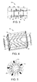
FIG. 2 is a cross section of the waveguide applicator ofFIG. 1 ; -
FIG. 3 is an enlarged cross section of a reactive choke in the applicator ofFIG. 1 ; -
FIG. 4 is an enlarged cross section of a resistive choke in the application ofFIG. 1 ; and; -
FIG. 5 is a cross section of the tubular applicator ofFIG. 1 showing the electric-field pattern. - A microwave heating apparatus embodying features of the invention, including a tubular waveguide applicator, is shown in
FIGS. 1 and2 . Theapplicator 10 shown in this example is constructed of a single circular waveguide section having a cylindrical outer wall 11 forming a heating chamber. But the applicator could be constructed of a series of individual circular waveguide sections connected end to end. Theapplicator 10 hascircular flanges 12 at each end. Plastic orteflon ribs 14 extend radially inward from the inside surface of the metal waveguide walls. Theribs 14, which extend along the length of theapplicator 10, are spaced apart circumferentially around the inner circumference of the applicator. The plastic orteflon ribs 14 are transparent to microwaves. The ribs extend radially inward a distance sufficient to bound acentral bore 16 through the heating chamber through which articles, such as individual cylindrical items or a continuous cylindrical strand, can pass. Theribs 14 center and guide the articles through thecentral bore 16. - A
microwave source 17 injectsmicrowaves 18, for example, at 915 MHz or 2540 MHz, into thewaveguide applicator 10 through arectangular waveguide feed 20 at anentrance end 22 of the applicator. The microwaves propagate along thewaveguide applicator 10 from theentrance end 22 to anexit end 23. The microwaves travel through the interior of theapplicator 10 in a direction ofpropagation 24 parallel to the axis 25 of the applicator. Microwave energy unabsorbed by the articles to be treated in the heating chamber exits theexit end 23 through arectangular waveguide segment 21 to adummy load 26, which prevents reflections back into the applicator. But it would also be possible to operate without a dummy load and allow the microwave energy to reflect back through theapplicator 10 toward theentrance end 22 and, in that way, double the effective length of the applicator. Theshorter sides 27 of therectangular waveguide feed 20, which define the feed's E plane, are perpendicular to the axis 25 of theapplicator 10 to produce an electric field pattern in which the TE01 mode is dominant. - As shown in
FIG. 5 , the TE01 mode produces an electric field with circular symmetry in theapplicator 10 and with its maximum electric-field intensity midway between the centerline and the cylindrical outer wall 11 of the applicator. This increased field intensity between the center and the wall is indicated by the bolder anddenser arrows 28 concentrically circling the centerline in the electric-field pattern shown inFIG. 5 . The magnitude of the electric field at any position along the applicator varies sinusoidally with the passing traveling microwave with reversals of direction every half cycle. Because the field intensity is greatest near theinner ends 30 of theguide ribs 14, theapplicator 10 is especially useful in applications that require the outer circumference of the cylindrical article to be heated. - As shown in
FIG. 2 ,cylindrical articles 32 enter the verticallyoriented applicator 10 at the upper end and fall through the applicator aided by gravity. Thearticles 32 advance through theapplicator 10 in or opposite to the direction ofpropagation 24 of the microwaves. The articles could be advanced through the applicator by an injected air stream instead of or in addition to gravity. As the articles fall, the microwaves heat the outer portions. For large-diameter articles the central bore has to be relatively large with respect to the cross-sectional dimensions of thewaveguide applicator 10. For that reason leakage of microwave energy through the large openings at theends chokes - The
chokes 34 closer to the applicator are reactive chokes that reflect microwave energy back into the applicator. Thereactive chokes 34 are positioned at theends applicator 10. Thereactive chokes 34 shown inFIG. 3 in more detail are constructed of four metalcircular waveguide segments applicator 10, or of a choke box 42 (FIG. 1 ) with screws, for example. Theleft-most segment 38 inFIG. 3 is a flanged cylindrical metallic tube having a circular bore. The identical interiormetallic waveguide segments diameter section 44 and a large-diameter section 45. The small-diameter section 44 has the same inner diameter as theleft-most segment 38. Theright-most segment 36 is the same as theinterior segments transparent ring 46 having the same inner diameter as the small-diameter sections 44, 44' is retained in the large-diameter end of eachinterior waveguide segment right-most segment 36. When the waveguide segments are fastened to each other, therings 46 are clamped in place and form a continuous smooth bore with the small-diameter sections 44, 44' and the bore of theleft-most segment 38. The smooth bore allows cylindrical articles to pass through without snagging.Air gaps 48 are formed between the walls of the large-diameter sections 45 and therings 46. Theair gaps 48 are spaced apart axially on quarter-wavelength centers (about 2.9 cm at 2540 MHz). The quarter-wavelength spacing of the steps in the waveguide's diameter provides choking that reduces the leakage of microwave energy. - Because of the large opening required to accommodate large-diameter articles entering and exiting the
reactive chokes 34, the reactive chokes may not reduce leakage enough. So resistive, absorbing choke boxes 42 (FIG. 1 ) are connected in series with thereactive chokes 34. The resistive chokes 42 are shown in more detail inFIG. 4 . Thechoke box 42 is shown as a rectangular box inFIG. 4 , but it could be another shape, such as circular or elliptic cylindrical. The dimensions of thechoke box 42 are greater than the diameter of the bore formed in a plastic orteflon tube 50 extending centrally through the choke box. V-shaped, conductivemetallic vanes 52 arranged in a chevron pattern havecentral apertures 54 to receive the microwave-transparent tube 50 that guides the articles centrally through thechoke box 42. Thevanes 52 are attached at their opposite ends to one pair ofside walls 56 of the choke box.Openings 57 inend walls 58 are aligned withcentral apertures 54 in the vanes to admit thetube 50 and guide articles centrally through the choke and into the applicator. The metallic vanes are coated with a dielectric material, such as Eccosorb, that absorbs microwave energy. Like the steps in thereactive chokes 34, the vanes are spaced apart in the axial direction by a quarter of the wavelength of the microwave radiation. The combination of the reactive and resistive chokes reduces the leakage to a level 60 dB below the power level of the microwave source 17 (FIG. 1 ). - Preferred features of the present invention will now be described by way of reference to the clauses below:
- 1. A microwave heating apparatus comprising:
- a tubular waveguide applicator having a first end and an opposite second end and a circular cross section and forming a heating chamber between the first and second ends with an axis along the centerline of the tubular waveguide applicator;
- a microwave source;
- a waveguide feed connected between the microwave source and the tubular waveguide applicator at the first end to propagate microwaves through the tubular waveguide applicator from the first end to the second end with a dominant TE01 field pattern in the heating chamber;
- a first resistive choke connected in series with the tubular waveguide applicator at the first end and a second resistive choke connected in series the tubular waveguide applicator at the second end, wherein each of the first and second resistive chokes includes:
- opposite ends having openings;
- a plurality of conductive vanes covered with a microwave-absorbent material and spaced apart along the axis in a chevron pattern, wherein the conductive vanes have apertures aligned with the openings in the opposite ends of the first and second resistive chokes and with the heating chamber to guide articles to be treated in the heating chamber through the first and second resistive chokes.
- 2. A microwave heating apparatus as in clause 1 further comprising microwave-transparent tubes extending through the central apertures and the openings in the first and second resistive chokes to guide articles to be heated in the heating chamber through the resistive chokes.
- 3. A microwave heating apparatus as in clause 1 or 2 further comprising a first reactive choke disposed in series with the tubular waveguide applicator between the first resistive choke and the first end of the tubular waveguide applicator and a second reactive choke disposed in series with the tubular waveguide applicator between the second resistive choke and the second end of the tubular waveguide applicator.
- 4. A microwave heating apparatus as in any one of the preceding clauses wherein the conductive vanes are V-shaped.
- 5. A microwave heating apparatus as in any one of the preceding clauses wherein the tubular waveguide is arranged with its axis vertical and articles to be heated advance by gravity through the heating chamber.
- 6. A microwave heating apparatus comprising:
- a tubular waveguide applicator having a cylindrical outer wall terminating in a first end and an opposite second end to form a heating chamber with a circular cross section between the first and second ends with an axis along the centerline of the heating chamber;
- a microwave source supplying microwave energy into the tubular waveguide applicator;
- a first reactive choke disposed in series with the tubular waveguide applicator at the first end of the tubular waveguide applicator;
- a second reactive choke disposed in series with the tubular waveguide applicator at the second end of the tubular waveguide applicator;
- a first resistive choke connected in series with the tubular waveguide applicator and the first reactive choke; and
- a second resistive choke connected in series with the tubular waveguide applicator and the second reactive choke.
- 7. A microwave heating apparatus as in clause 6 wherein each of the first and second resistive chokes includes a plurality of V-shaped conductive vanes covered with a microwave-absorbent material and spaced apart along the axis in a chevron pattern, wherein the V-shaped conductive vanes have central apertures aligned with the heating chamber to pass articles to be treated in the heating chamber through the first and second resistive chokes.
- 8. A microwave heating apparatus as in clause 7 further comprising microwave-transparent tubes extending through the central apertures in the first and second resistive chokes to guide articles to be heated in the heating chamber through the first and second resistive chokes.
- 9. A microwave heating apparatus as in any one of clauses 6 to 8 wherein the first reactive choke is between the first resistive choke and the first end of the tubular waveguide applicator and the second reactive choke is disposed between the second resistive choke and the second end of the tubular waveguide applicator.
- 10. A microwave heating apparatus as in any one of clauses 6 to 9 wherein the microwave source supplies microwaves with a dominant TE01 mode into the tubular waveguide applicator to produce a maximum electric field in the heating chamber midway between the centerline and the outer walls of the tubular waveguide applicator.
- 11. A microwave heating apparatus as in any one of clauses 6 to 10 further comprising a plurality of microwave-transparent ribs circumferentially spaced apart and extending inward from the cylindrical outer wall into the heating chamber to inner ends bounding a central bore to guide articles passing through the heating chamber.
Claims (11)
- A microwave heating apparatus comprising:a tubular waveguide applicator having a first end and an opposite second end and a circular cross section and forming a heating chamber between the first and second ends with an axis along the centerline of the tubular waveguide applicator;a microwave source;a waveguide feed connected between the microwave source and the tubular waveguide applicator at the first end to propagate microwaves through the tubular waveguide applicator from the first end to the second end with a dominant TE01 field pattern in the heating chamber;a first resistive choke connected in series with the tubular waveguide applicator at the first end and a second resistive choke connected in series the tubular waveguide applicator at the second end, wherein each of the first and second resistive chokes includes:opposite ends having openings;a plurality of conductive vanes covered with a microwave-absorbent material and spaced apart along the axis in a chevron pattern, wherein the conductive vanes have apertures aligned with the openings in the opposite ends of the first and second resistive chokes and with the heating chamber to guide articles to be treated in the heating chamber through the first and second resistive chokes.
- A microwave heating apparatus as in claim 1 further comprising microwave-transparent tubes extending through the central apertures and the openings in the first and second resistive chokes to guide articles to be heated in the heating chamber through the resistive chokes.
- A microwave heating apparatus as in claim 1 further comprising a first reactive choke disposed in series with the tubular waveguide applicator between the first resistive choke and the first end of the tubular waveguide applicator and a second reactive choke disposed in series with the tubular waveguide applicator between the second resistive choke and the second end of the tubular waveguide applicator.
- A microwave heating apparatus as in claim 1 wherein the conductive vanes are V-shaped.
- A microwave heating apparatus as in claim 1 wherein the tubular waveguide is arranged with its axis vertical and articles to be heated advance by gravity through the heating chamber.
- A microwave heating apparatus comprising:a tubular waveguide applicator having a cylindrical outer wall terminating in a first end and an opposite second end to form a heating chamber with a circular cross section between the first and second ends with an axis along the centerline of the heating chamber;a microwave source supplying microwave energy into the tubular waveguide applicator;a first reactive choke disposed in series with the tubular waveguide applicator at the first end of the tubular waveguide applicator;a second reactive choke disposed in series with the tubular waveguide applicator at the second end of the tubular waveguide applicator;a first resistive choke connected in series with the tubular waveguide applicator and the first reactive choke; anda second resistive choke connected in series with the tubular waveguide applicator and the second reactive choke.
- A microwave heating apparatus as in claim 6 wherein each of the first and second resistive chokes includes a plurality of V-shaped conductive vanes covered with a microwave-absorbent material and spaced apart along the axis in a chevron pattern, wherein the V-shaped conductive vanes have central apertures aligned with the heating chamber to pass articles to be treated in the heating chamber through the first and second resistive chokes.
- A microwave heating apparatus as in claim 7 further comprising microwave-transparent tubes extending through the central apertures in the first and second resistive chokes to guide articles to be heated in the heating chamber through the first and second resistive chokes.
- A microwave heating apparatus as in claim 6 wherein the first reactive choke is between the first resistive choke and the first end of the tubular waveguide applicator and the second reactive choke is disposed between the second resistive choke and the second end of the tubular waveguide applicator.
- A microwave heating apparatus as in claim 6 wherein the microwave source supplies microwaves with a dominant TE01 mode into the tubular waveguide applicator to produce a maximum electric field in the heating chamber midway between the centerline and the outer walls of the tubular waveguide applicator.
- A microwave heating apparatus as in claim 6 further comprising a plurality of microwave-transparent ribs circumferentially spaced apart and extending inward from the cylindrical outer wall into the heating chamber to inner ends bounding a central bore to guide articles passing through the heating chamber.
Applications Claiming Priority (1)
| Application Number | Priority Date | Filing Date | Title |
|---|---|---|---|
| US14/453,820 US9642194B2 (en) | 2014-08-07 | 2014-08-07 | Tubular choked waveguide applicator |
Publications (2)
| Publication Number | Publication Date |
|---|---|
| EP2983455A1 true EP2983455A1 (en) | 2016-02-10 |
| EP2983455B1 EP2983455B1 (en) | 2017-11-29 |
Family
ID=53783131
Family Applications (1)
| Application Number | Title | Priority Date | Filing Date |
|---|---|---|---|
| EP15179898.0A Not-in-force EP2983455B1 (en) | 2014-08-07 | 2015-08-05 | Tubular choked waveguide applicator |
Country Status (8)
| Country | Link |
|---|---|
| US (1) | US9642194B2 (en) |
| EP (1) | EP2983455B1 (en) |
| JP (1) | JP6616118B2 (en) |
| CN (1) | CN105376888B (en) |
| AU (1) | AU2015207975B2 (en) |
| BR (1) | BR102015019022A2 (en) |
| CA (1) | CA2899415A1 (en) |
| MX (1) | MX347880B (en) |
Cited By (1)
| Publication number | Priority date | Publication date | Assignee | Title |
|---|---|---|---|---|
| WO2017205034A2 (en) | 2016-05-27 | 2017-11-30 | Mks Instruments, Inc. | Compact microwave plasma applicator utilizing conjoining electric fields |
Families Citing this family (9)
| Publication number | Priority date | Publication date | Assignee | Title |
|---|---|---|---|---|
| WO2017165664A1 (en) | 2016-03-23 | 2017-09-28 | A.L.M Holding Company | Batch asphalt mix plant |
| US20170333258A1 (en) * | 2016-05-19 | 2017-11-23 | The Procter & Gamble Company | Method and apparatus for circularly polarized microwave product treatment |
| MX392386B (en) * | 2016-07-28 | 2025-03-24 | Guangdong Oppo Mobile Telecommunications Corp Ltd | Communication method, network equipment, and terminal equipment |
| US11039631B2 (en) * | 2017-10-19 | 2021-06-22 | Harold Dail Kimrey, JR. | Compact radio frequency heating of packaged articles |
| MX2020010442A (en) | 2018-04-03 | 2020-11-24 | Sinnovatek Inc | SYSTEM AND METHOD FOR THE CONTINUOUS THERMAL TREATMENT OF A FLUID PRODUCT. |
| US20200313267A1 (en) * | 2019-04-01 | 2020-10-01 | Marion Process Solutions, Inc. | Modular Microwave Choke Assembly |
| AU2020298486B2 (en) | 2019-07-01 | 2025-03-27 | A.L.M Holding Company | Microwave heating system with suppression tunnel and related features |
| US12690098B2 (en) | 2021-05-19 | 2026-07-21 | A.L.M. Holding Company | Microwave waste heating system and related features |
| AU2022463711A1 (en) | 2021-09-08 | 2024-03-07 | A.L.M. Holding Company | Microwave heating applied to mining and related features |
Citations (6)
| Publication number | Priority date | Publication date | Assignee | Title |
|---|---|---|---|---|
| US3590202A (en) * | 1970-02-24 | 1971-06-29 | Bechtel Corp | Construction for tuning microwave heating applicator |
| US3858022A (en) * | 1972-04-21 | 1974-12-31 | Microdry Corp | Microwave applicator |
| US4488027A (en) * | 1983-06-06 | 1984-12-11 | Raytheon Company | Leakage suppression tunnel for conveyorized microwave oven |
| US4497759A (en) | 1981-12-24 | 1985-02-05 | Nippon Telegraph & Telephone Public Corporation | Drawing of polyoxymethylene using dielectric heating |
| GB2262421A (en) * | 1991-12-10 | 1993-06-16 | Atomic Energy Authority Uk | The removal of organic materials from a gas by microwaves |
| DE102013009064B3 (en) * | 2013-05-28 | 2014-07-31 | Püschner GmbH + Co. KG | Continuous microwave furnace e.g. microwave oven, has microwave generator which is formed in microwave mode in specific mode orthogonally and is coupled with respective single mode microwave channel |
Family Cites Families (34)
| Publication number | Priority date | Publication date | Assignee | Title |
|---|---|---|---|---|
| GB902128A (en) | 1959-08-19 | 1962-07-25 | Decca Ltd | Improvements in or relating to waveguide couplings |
| US3442663A (en) | 1966-01-24 | 1969-05-06 | Tee Pak Inc | Method of treating a sausage casing with a release coating and product resulting therefrom |
| US3457385A (en) | 1966-07-07 | 1969-07-22 | Canadian Patents Dev | Apparatus for dielectric heating |
| US3461261A (en) | 1966-10-31 | 1969-08-12 | Du Pont | Heating apparatus |
| US3665141A (en) * | 1970-07-01 | 1972-05-23 | Dca Food Ind | End trap for microwave oven |
| JPS4910377B1 (en) * | 1970-12-29 | 1974-03-09 | ||
| US4006339A (en) * | 1975-12-31 | 1977-02-01 | General Electric Company | Microwave heating apparatus with multiple coupling elements and microwave power sources |
| US4330946A (en) | 1980-09-23 | 1982-05-25 | Ralph S. Tillitt | High efficiency material drying |
| WO1984002570A1 (en) | 1982-12-22 | 1984-07-05 | Buehler Ag Geb | Device and method for processing alimentary pastes by microwaves |
| SE460499B (en) | 1988-07-15 | 1989-10-16 | Loeoef Nils Oskar T | SEAT AND DEVICE FOR DRYING OF TANKS AND SIMILAR PRODUCTS |
| GB9126179D0 (en) * | 1991-12-10 | 1992-02-12 | Atomic Energy Authority Uk | The removal of organic materials from process gas streams |
| JP2567415Y2 (en) * | 1992-06-29 | 1998-04-02 | 新日本無線株式会社 | Microwave heating equipment |
| US5314647A (en) | 1992-07-20 | 1994-05-24 | Eastman Kodak Company | Method of making cellulose ester photographic film base |
| JPH0641096U (en) * | 1992-10-30 | 1994-05-31 | 新日本無線株式会社 | Microwave heating device |
| US5955126A (en) | 1993-09-21 | 1999-09-21 | Viskase Corporation | Self-coloring food casing |
| CN1061508C (en) * | 1996-10-18 | 2001-01-31 | 蔡同福 | Means for preventing microwave leakage for transmission equipment |
| US5869817A (en) | 1997-03-06 | 1999-02-09 | General Mills, Inc. | Tunable cavity microwave applicator |
| US5834744A (en) | 1997-09-08 | 1998-11-10 | The Rubbright Group | Tubular microwave applicator |
| DE10017172A1 (en) | 2000-04-07 | 2001-10-11 | Hartmut Brettschneider | Process for making a casing of greater length for food |
| US6322832B1 (en) | 2000-10-31 | 2001-11-27 | Misonix Incorporated | Manufacturing method and apparatus utilizing reusable deformable support |
| US6326039B1 (en) | 2000-10-31 | 2001-12-04 | Misonix Incorporated | Skinless sausage or frankfurter manufacturing method and apparatus utilizing reusable deformable support |
| SE521315C2 (en) | 2001-12-17 | 2003-10-21 | A Cell Acetyl Cellulosics | Microwave system for heating bulky elongated loads |
| US20030209542A1 (en) * | 2002-05-13 | 2003-11-13 | Harris George M. | Apparatus and method for microwave processing of food products |
| DE102004051298A1 (en) | 2004-10-20 | 2006-04-27 | Kalle Gmbh | Nonwoven fabric with improved wet and alkaline strength and cellulose hemp-based food casing produced therefrom |
| US8426785B2 (en) | 2007-10-15 | 2013-04-23 | E I Du Pont De Nemours And Company | Microwave field director structure with vanes having a conductive material thereon |
| JP4832403B2 (en) * | 2007-10-23 | 2011-12-07 | 大和製罐株式会社 | Continuous and uniform heating equipment for food by circular polarization |
| EP2243377A1 (en) | 2009-04-21 | 2010-10-27 | Unilever N.V. | Sausage |
| US20100311296A1 (en) | 2009-06-09 | 2010-12-09 | Boehmer Brian E | Dyed cellulose comminution sheet, dyed nonwoven material, and processes for their production |
| DE102010007658A1 (en) | 2010-02-10 | 2012-05-10 | Case Tech Gmbh | Method for drying tubular casings by microwaves |
| BR112013004565A2 (en) | 2010-09-01 | 2016-09-06 | Lbp Mfg Inc | process of accelerating activation of adhesive / thermosetting coatings used in the manufacture of packaging substrates |
| MX2013003852A (en) * | 2010-10-07 | 2013-07-03 | Milt D Mathis | Microwave rotary kiln. |
| EP2636314B1 (en) | 2010-11-02 | 2015-08-12 | Nippon Suisan Kaisha, Ltd. | Process for production of protein-containing food employing continuous heating method by internal heating |
| CN102316616B (en) * | 2011-05-26 | 2013-03-20 | 云南昆船瑞升烟草加工新技术有限责任公司 | A rotary dynamic sealing type microwave leakage prevention device |
| JP5787289B2 (en) | 2011-06-20 | 2015-09-30 | ミクロ電子株式会社 | Heating device using microwaves |
-
2014
- 2014-08-07 US US14/453,820 patent/US9642194B2/en not_active Expired - Fee Related
-
2015
- 2015-08-03 AU AU2015207975A patent/AU2015207975B2/en not_active Expired - Fee Related
- 2015-08-03 JP JP2015153465A patent/JP6616118B2/en not_active Expired - Fee Related
- 2015-08-05 EP EP15179898.0A patent/EP2983455B1/en not_active Not-in-force
- 2015-08-05 CA CA2899415A patent/CA2899415A1/en not_active Abandoned
- 2015-08-07 MX MX2015010222A patent/MX347880B/en active IP Right Grant
- 2015-08-07 CN CN201510483009.7A patent/CN105376888B/en not_active Expired - Fee Related
- 2015-08-07 BR BR102015019022-0A patent/BR102015019022A2/en not_active Application Discontinuation
Patent Citations (6)
| Publication number | Priority date | Publication date | Assignee | Title |
|---|---|---|---|---|
| US3590202A (en) * | 1970-02-24 | 1971-06-29 | Bechtel Corp | Construction for tuning microwave heating applicator |
| US3858022A (en) * | 1972-04-21 | 1974-12-31 | Microdry Corp | Microwave applicator |
| US4497759A (en) | 1981-12-24 | 1985-02-05 | Nippon Telegraph & Telephone Public Corporation | Drawing of polyoxymethylene using dielectric heating |
| US4488027A (en) * | 1983-06-06 | 1984-12-11 | Raytheon Company | Leakage suppression tunnel for conveyorized microwave oven |
| GB2262421A (en) * | 1991-12-10 | 1993-06-16 | Atomic Energy Authority Uk | The removal of organic materials from a gas by microwaves |
| DE102013009064B3 (en) * | 2013-05-28 | 2014-07-31 | Püschner GmbH + Co. KG | Continuous microwave furnace e.g. microwave oven, has microwave generator which is formed in microwave mode in specific mode orthogonally and is coupled with respective single mode microwave channel |
Cited By (2)
| Publication number | Priority date | Publication date | Assignee | Title |
|---|---|---|---|---|
| WO2017205034A2 (en) | 2016-05-27 | 2017-11-30 | Mks Instruments, Inc. | Compact microwave plasma applicator utilizing conjoining electric fields |
| EP3465728A4 (en) * | 2016-05-27 | 2020-01-01 | MKS Instruments, Inc. | Compact microwave plasma applicator utilizing conjoining electric fields |
Also Published As
| Publication number | Publication date |
|---|---|
| US20160044750A1 (en) | 2016-02-11 |
| AU2015207975A1 (en) | 2016-02-25 |
| BR102015019022A2 (en) | 2018-03-13 |
| MX2015010222A (en) | 2016-04-26 |
| AU2015207975B2 (en) | 2020-05-07 |
| EP2983455B1 (en) | 2017-11-29 |
| US9642194B2 (en) | 2017-05-02 |
| CN105376888B (en) | 2020-11-13 |
| JP2016039140A (en) | 2016-03-22 |
| JP6616118B2 (en) | 2019-12-04 |
| CN105376888A (en) | 2016-03-02 |
| CA2899415A1 (en) | 2016-02-07 |
| MX347880B (en) | 2017-05-16 |
Similar Documents
| Publication | Publication Date | Title |
|---|---|---|
| US9642194B2 (en) | Tubular choked waveguide applicator | |
| JP2016039140A5 (en) | ||
| US3715551A (en) | Twisted waveguide applicator | |
| US3461261A (en) | Heating apparatus | |
| EP3074201B1 (en) | Tubular waveguide applicator | |
| CN202918530U (en) | Microwave heating device | |
| US3307010A (en) | Arrangements for the treatment of goods by microwaves, especially in a continuous process | |
| US6072167A (en) | Enhanced uniformity in a length independent microwave applicator | |
| TW201922050A (en) | Device for processing products by microwave | |
| CN113015280B (en) | Microwave suppressor and microwave device | |
| NZ710702A (en) | Tubular choked waveguide applicator | |
| US9380651B2 (en) | Microwave choke system for use in heating articles under vacuum | |
| US3688068A (en) | Continuous microwave heating or cooking system and method | |
| US20150351165A1 (en) | Microwave barrier system for use in heating articles under vacuum | |
| US3491222A (en) | Microwave heating applicator | |
| RO131921B1 (en) | Microwave heating device | |
| KR102780461B1 (en) | Plasma generator by resonant waveguide | |
| EP3987889B1 (en) | Electromagnetic heating reactor | |
| EP2605267A2 (en) | An apparatus for performing a plasma chemical vapour deposition process | |
| RU130178U1 (en) | CAMERA FOR HIGH-FREQUENCY HEATING OF DIELECTRICIANS | |
| RU170944U1 (en) | WAVEGUIDE LOAD FOR PROCESSING SOLUTIONS, LIQUIDS, AND BULK MATERIALS | |
| SU1562981A1 (en) | Device for treating extended dielectric articles | |
| UA57960A (en) | DEVICE FOR microwave TREATMENT OF FLUIDS | |
| ITRM20130162A1 (en) | EXTENDED MICROWAVE POWERED LAMP |
Legal Events
| Date | Code | Title | Description |
|---|---|---|---|
| PUAI | Public reference made under article 153(3) epc to a published international application that has entered the european phase |
Free format text: ORIGINAL CODE: 0009012 |
|
| AK | Designated contracting states |
Kind code of ref document: A1 Designated state(s): AL AT BE BG CH CY CZ DE DK EE ES FI FR GB GR HR HU IE IS IT LI LT LU LV MC MK MT NL NO PL PT RO RS SE SI SK SM TR |
|
| AX | Request for extension of the european patent |
Extension state: BA ME |
|
| RIN1 | Information on inventor provided before grant (corrected) |
Inventor name: SHUPING, DONALD Inventor name: WILBER, WILLIAM |
|
| 17P | Request for examination filed |
Effective date: 20160809 |
|
| RBV | Designated contracting states (corrected) |
Designated state(s): AL AT BE BG CH CY CZ DE DK EE ES FI FR GB GR HR HU IE IS IT LI LT LU LV MC MK MT NL NO PL PT RO RS SE SI SK SM TR |
|
| GRAP | Despatch of communication of intention to grant a patent |
Free format text: ORIGINAL CODE: EPIDOSNIGR1 |
|
| INTG | Intention to grant announced |
Effective date: 20170619 |
|
| RIN1 | Information on inventor provided before grant (corrected) |
Inventor name: WILBER, WILLIAM Inventor name: SHUPING, DONALD |
|
| GRAS | Grant fee paid |
Free format text: ORIGINAL CODE: EPIDOSNIGR3 |
|
| GRAA | (expected) grant |
Free format text: ORIGINAL CODE: 0009210 |
|
| AK | Designated contracting states |
Kind code of ref document: B1 Designated state(s): AL AT BE BG CH CY CZ DE DK EE ES FI FR GB GR HR HU IE IS IT LI LT LU LV MC MK MT NL NO PL PT RO RS SE SI SK SM TR |
|
| REG | Reference to a national code |
Ref country code: CH Ref legal event code: EP |
|
| REG | Reference to a national code |
Ref country code: AT Ref legal event code: REF Ref document number: 951456 Country of ref document: AT Kind code of ref document: T Effective date: 20171215 |
|
| REG | Reference to a national code |
Ref country code: IE Ref legal event code: FG4D |
|
| REG | Reference to a national code |
Ref country code: DE Ref legal event code: R096 Ref document number: 602015006289 Country of ref document: DE |
|
| REG | Reference to a national code |
Ref country code: NL Ref legal event code: MP Effective date: 20171129 |
|
| REG | Reference to a national code |
Ref country code: LT Ref legal event code: MG4D |
|
| REG | Reference to a national code |
Ref country code: AT Ref legal event code: MK05 Ref document number: 951456 Country of ref document: AT Kind code of ref document: T Effective date: 20171129 |
|
| PG25 | Lapsed in a contracting state [announced via postgrant information from national office to epo] |
Ref country code: LT Free format text: LAPSE BECAUSE OF FAILURE TO SUBMIT A TRANSLATION OF THE DESCRIPTION OR TO PAY THE FEE WITHIN THE PRESCRIBED TIME-LIMIT Effective date: 20171129 Ref country code: FI Free format text: LAPSE BECAUSE OF FAILURE TO SUBMIT A TRANSLATION OF THE DESCRIPTION OR TO PAY THE FEE WITHIN THE PRESCRIBED TIME-LIMIT Effective date: 20171129 Ref country code: SE Free format text: LAPSE BECAUSE OF FAILURE TO SUBMIT A TRANSLATION OF THE DESCRIPTION OR TO PAY THE FEE WITHIN THE PRESCRIBED TIME-LIMIT Effective date: 20171129 Ref country code: ES Free format text: LAPSE BECAUSE OF FAILURE TO SUBMIT A TRANSLATION OF THE DESCRIPTION OR TO PAY THE FEE WITHIN THE PRESCRIBED TIME-LIMIT Effective date: 20171129 Ref country code: NO Free format text: LAPSE BECAUSE OF FAILURE TO SUBMIT A TRANSLATION OF THE DESCRIPTION OR TO PAY THE FEE WITHIN THE PRESCRIBED TIME-LIMIT Effective date: 20180228 |
|
| PG25 | Lapsed in a contracting state [announced via postgrant information from national office to epo] |
Ref country code: HR Free format text: LAPSE BECAUSE OF FAILURE TO SUBMIT A TRANSLATION OF THE DESCRIPTION OR TO PAY THE FEE WITHIN THE PRESCRIBED TIME-LIMIT Effective date: 20171129 Ref country code: AT Free format text: LAPSE BECAUSE OF FAILURE TO SUBMIT A TRANSLATION OF THE DESCRIPTION OR TO PAY THE FEE WITHIN THE PRESCRIBED TIME-LIMIT Effective date: 20171129 Ref country code: GR Free format text: LAPSE BECAUSE OF FAILURE TO SUBMIT A TRANSLATION OF THE DESCRIPTION OR TO PAY THE FEE WITHIN THE PRESCRIBED TIME-LIMIT Effective date: 20180301 Ref country code: RS Free format text: LAPSE BECAUSE OF FAILURE TO SUBMIT A TRANSLATION OF THE DESCRIPTION OR TO PAY THE FEE WITHIN THE PRESCRIBED TIME-LIMIT Effective date: 20171129 Ref country code: LV Free format text: LAPSE BECAUSE OF FAILURE TO SUBMIT A TRANSLATION OF THE DESCRIPTION OR TO PAY THE FEE WITHIN THE PRESCRIBED TIME-LIMIT Effective date: 20171129 Ref country code: BG Free format text: LAPSE BECAUSE OF FAILURE TO SUBMIT A TRANSLATION OF THE DESCRIPTION OR TO PAY THE FEE WITHIN THE PRESCRIBED TIME-LIMIT Effective date: 20180228 |
|
| PG25 | Lapsed in a contracting state [announced via postgrant information from national office to epo] |
Ref country code: NL Free format text: LAPSE BECAUSE OF FAILURE TO SUBMIT A TRANSLATION OF THE DESCRIPTION OR TO PAY THE FEE WITHIN THE PRESCRIBED TIME-LIMIT Effective date: 20171129 |
|
| PG25 | Lapsed in a contracting state [announced via postgrant information from national office to epo] |
Ref country code: DK Free format text: LAPSE BECAUSE OF FAILURE TO SUBMIT A TRANSLATION OF THE DESCRIPTION OR TO PAY THE FEE WITHIN THE PRESCRIBED TIME-LIMIT Effective date: 20171129 Ref country code: CY Free format text: LAPSE BECAUSE OF FAILURE TO SUBMIT A TRANSLATION OF THE DESCRIPTION OR TO PAY THE FEE WITHIN THE PRESCRIBED TIME-LIMIT Effective date: 20171129 Ref country code: EE Free format text: LAPSE BECAUSE OF FAILURE TO SUBMIT A TRANSLATION OF THE DESCRIPTION OR TO PAY THE FEE WITHIN THE PRESCRIBED TIME-LIMIT Effective date: 20171129 Ref country code: CZ Free format text: LAPSE BECAUSE OF FAILURE TO SUBMIT A TRANSLATION OF THE DESCRIPTION OR TO PAY THE FEE WITHIN THE PRESCRIBED TIME-LIMIT Effective date: 20171129 Ref country code: SK Free format text: LAPSE BECAUSE OF FAILURE TO SUBMIT A TRANSLATION OF THE DESCRIPTION OR TO PAY THE FEE WITHIN THE PRESCRIBED TIME-LIMIT Effective date: 20171129 |
|
| REG | Reference to a national code |
Ref country code: DE Ref legal event code: R097 Ref document number: 602015006289 Country of ref document: DE |
|
| PG25 | Lapsed in a contracting state [announced via postgrant information from national office to epo] |
Ref country code: SM Free format text: LAPSE BECAUSE OF FAILURE TO SUBMIT A TRANSLATION OF THE DESCRIPTION OR TO PAY THE FEE WITHIN THE PRESCRIBED TIME-LIMIT Effective date: 20171129 Ref country code: IT Free format text: LAPSE BECAUSE OF FAILURE TO SUBMIT A TRANSLATION OF THE DESCRIPTION OR TO PAY THE FEE WITHIN THE PRESCRIBED TIME-LIMIT Effective date: 20171129 Ref country code: RO Free format text: LAPSE BECAUSE OF FAILURE TO SUBMIT A TRANSLATION OF THE DESCRIPTION OR TO PAY THE FEE WITHIN THE PRESCRIBED TIME-LIMIT Effective date: 20171129 Ref country code: PL Free format text: LAPSE BECAUSE OF FAILURE TO SUBMIT A TRANSLATION OF THE DESCRIPTION OR TO PAY THE FEE WITHIN THE PRESCRIBED TIME-LIMIT Effective date: 20171129 |
|
| PLBE | No opposition filed within time limit |
Free format text: ORIGINAL CODE: 0009261 |
|
| STAA | Information on the status of an ep patent application or granted ep patent |
Free format text: STATUS: NO OPPOSITION FILED WITHIN TIME LIMIT |
|
| 26N | No opposition filed |
Effective date: 20180830 |
|
| PG25 | Lapsed in a contracting state [announced via postgrant information from national office to epo] |
Ref country code: SI Free format text: LAPSE BECAUSE OF FAILURE TO SUBMIT A TRANSLATION OF THE DESCRIPTION OR TO PAY THE FEE WITHIN THE PRESCRIBED TIME-LIMIT Effective date: 20171129 |
|
| PG25 | Lapsed in a contracting state [announced via postgrant information from national office to epo] |
Ref country code: MC Free format text: LAPSE BECAUSE OF FAILURE TO SUBMIT A TRANSLATION OF THE DESCRIPTION OR TO PAY THE FEE WITHIN THE PRESCRIBED TIME-LIMIT Effective date: 20171129 |
|
| REG | Reference to a national code |
Ref country code: CH Ref legal event code: PL |
|
| PG25 | Lapsed in a contracting state [announced via postgrant information from national office to epo] |
Ref country code: LU Free format text: LAPSE BECAUSE OF NON-PAYMENT OF DUE FEES Effective date: 20180805 Ref country code: CH Free format text: LAPSE BECAUSE OF NON-PAYMENT OF DUE FEES Effective date: 20180831 Ref country code: LI Free format text: LAPSE BECAUSE OF NON-PAYMENT OF DUE FEES Effective date: 20180831 |
|
| REG | Reference to a national code |
Ref country code: BE Ref legal event code: MM Effective date: 20180831 |
|
| REG | Reference to a national code |
Ref country code: IE Ref legal event code: MM4A |
|
| REG | Reference to a national code |
Ref country code: DE Ref legal event code: R082 Ref document number: 602015006289 Country of ref document: DE Representative=s name: ETL WABLAT & KOLLEGEN PATENT- UND RECHTSANWALT, DE Ref country code: DE Ref legal event code: R082 Ref document number: 602015006289 Country of ref document: DE Representative=s name: ETL IP PATENT- UND RECHTSANWALTSGESELLSCHAFT M, DE |
|
| PG25 | Lapsed in a contracting state [announced via postgrant information from national office to epo] |
Ref country code: IE Free format text: LAPSE BECAUSE OF NON-PAYMENT OF DUE FEES Effective date: 20180805 |
|
| PG25 | Lapsed in a contracting state [announced via postgrant information from national office to epo] |
Ref country code: FR Free format text: LAPSE BECAUSE OF NON-PAYMENT OF DUE FEES Effective date: 20180831 Ref country code: BE Free format text: LAPSE BECAUSE OF NON-PAYMENT OF DUE FEES Effective date: 20180831 |
|
| PGFP | Annual fee paid to national office [announced via postgrant information from national office to epo] |
Ref country code: DE Payment date: 20190715 Year of fee payment: 5 |
|
| PGFP | Annual fee paid to national office [announced via postgrant information from national office to epo] |
Ref country code: GB Payment date: 20190728 Year of fee payment: 5 |
|
| PG25 | Lapsed in a contracting state [announced via postgrant information from national office to epo] |
Ref country code: MT Free format text: LAPSE BECAUSE OF NON-PAYMENT OF DUE FEES Effective date: 20180805 |
|
| PG25 | Lapsed in a contracting state [announced via postgrant information from national office to epo] |
Ref country code: TR Free format text: LAPSE BECAUSE OF FAILURE TO SUBMIT A TRANSLATION OF THE DESCRIPTION OR TO PAY THE FEE WITHIN THE PRESCRIBED TIME-LIMIT Effective date: 20171129 |
|
| PG25 | Lapsed in a contracting state [announced via postgrant information from national office to epo] |
Ref country code: PT Free format text: LAPSE BECAUSE OF FAILURE TO SUBMIT A TRANSLATION OF THE DESCRIPTION OR TO PAY THE FEE WITHIN THE PRESCRIBED TIME-LIMIT Effective date: 20171129 |
|
| PG25 | Lapsed in a contracting state [announced via postgrant information from national office to epo] |
Ref country code: MK Free format text: LAPSE BECAUSE OF NON-PAYMENT OF DUE FEES Effective date: 20171129 Ref country code: HU Free format text: LAPSE BECAUSE OF FAILURE TO SUBMIT A TRANSLATION OF THE DESCRIPTION OR TO PAY THE FEE WITHIN THE PRESCRIBED TIME-LIMIT; INVALID AB INITIO Effective date: 20150805 |
|
| REG | Reference to a national code |
Ref country code: DE Ref legal event code: R082 Ref document number: 602015006289 Country of ref document: DE Representative=s name: ETL IP PATENT- UND RECHTSANWALTSGESELLSCHAFT M, DE |
|
| PG25 | Lapsed in a contracting state [announced via postgrant information from national office to epo] |
Ref country code: AL Free format text: LAPSE BECAUSE OF FAILURE TO SUBMIT A TRANSLATION OF THE DESCRIPTION OR TO PAY THE FEE WITHIN THE PRESCRIBED TIME-LIMIT Effective date: 20171129 Ref country code: IS Free format text: LAPSE BECAUSE OF FAILURE TO SUBMIT A TRANSLATION OF THE DESCRIPTION OR TO PAY THE FEE WITHIN THE PRESCRIBED TIME-LIMIT Effective date: 20180329 |
|
| REG | Reference to a national code |
Ref country code: DE Ref legal event code: R119 Ref document number: 602015006289 Country of ref document: DE |
|
| GBPC | Gb: european patent ceased through non-payment of renewal fee |
Effective date: 20200805 |
|
| PG25 | Lapsed in a contracting state [announced via postgrant information from national office to epo] |
Ref country code: DE Free format text: LAPSE BECAUSE OF NON-PAYMENT OF DUE FEES Effective date: 20210302 |
|
| PG25 | Lapsed in a contracting state [announced via postgrant information from national office to epo] |
Ref country code: GB Free format text: LAPSE BECAUSE OF NON-PAYMENT OF DUE FEES Effective date: 20200805 |