EP2983252A1 - Connector assembly having conductive holder members - Google Patents
Connector assembly having conductive holder members Download PDFInfo
- Publication number
- EP2983252A1 EP2983252A1 EP15179861.8A EP15179861A EP2983252A1 EP 2983252 A1 EP2983252 A1 EP 2983252A1 EP 15179861 A EP15179861 A EP 15179861A EP 2983252 A1 EP2983252 A1 EP 2983252A1
- Authority
- EP
- European Patent Office
- Prior art keywords
- holes
- posts
- tabs
- holder member
- holder
- Prior art date
- Legal status (The legal status is an assumption and is not a legal conclusion. Google has not performed a legal analysis and makes no representation as to the accuracy of the status listed.)
- Withdrawn
Links
- 230000005855 radiation Effects 0.000 claims abstract description 22
- 230000008961 swelling Effects 0.000 claims 1
- 230000013011 mating Effects 0.000 description 32
- 230000000712 assembly Effects 0.000 description 12
- 238000000429 assembly Methods 0.000 description 12
- 230000000694 effects Effects 0.000 description 7
- 239000004020 conductor Substances 0.000 description 3
- 239000000463 material Substances 0.000 description 3
- 239000007769 metal material Substances 0.000 description 3
- 230000001902 propagating effect Effects 0.000 description 3
- 239000011800 void material Substances 0.000 description 3
- 239000003989 dielectric material Substances 0.000 description 2
- 230000007704 transition Effects 0.000 description 2
- 230000000903 blocking effect Effects 0.000 description 1
- 230000015556 catabolic process Effects 0.000 description 1
- 230000003247 decreasing effect Effects 0.000 description 1
- 238000006731 degradation reaction Methods 0.000 description 1
- 238000002955 isolation Methods 0.000 description 1
- 238000004519 manufacturing process Methods 0.000 description 1
- 239000011159 matrix material Substances 0.000 description 1
Images




Classifications
-
- H—ELECTRICITY
- H01—ELECTRIC ELEMENTS
- H01R—ELECTRICALLY-CONDUCTIVE CONNECTIONS; STRUCTURAL ASSOCIATIONS OF A PLURALITY OF MUTUALLY-INSULATED ELECTRICAL CONNECTING ELEMENTS; COUPLING DEVICES; CURRENT COLLECTORS
- H01R13/00—Details of coupling devices of the kinds covered by groups H01R12/70 or H01R24/00 - H01R33/00
- H01R13/648—Protective earth or shield arrangements on coupling devices, e.g. anti-static shielding
- H01R13/658—High frequency shielding arrangements, e.g. against EMI [Electro-Magnetic Interference] or EMP [Electro-Magnetic Pulse]
- H01R13/6581—Shield structure
- H01R13/6585—Shielding material individually surrounding or interposed between mutually spaced contacts
- H01R13/6586—Shielding material individually surrounding or interposed between mutually spaced contacts for separating multiple connector modules
- H01R13/6587—Shielding material individually surrounding or interposed between mutually spaced contacts for separating multiple connector modules for mounting on PCBs
-
- H—ELECTRICITY
- H01—ELECTRIC ELEMENTS
- H01R—ELECTRICALLY-CONDUCTIVE CONNECTIONS; STRUCTURAL ASSOCIATIONS OF A PLURALITY OF MUTUALLY-INSULATED ELECTRICAL CONNECTING ELEMENTS; COUPLING DEVICES; CURRENT COLLECTORS
- H01R13/00—Details of coupling devices of the kinds covered by groups H01R12/70 or H01R24/00 - H01R33/00
- H01R13/648—Protective earth or shield arrangements on coupling devices, e.g. anti-static shielding
- H01R13/658—High frequency shielding arrangements, e.g. against EMI [Electro-Magnetic Interference] or EMP [Electro-Magnetic Pulse]
- H01R13/6581—Shield structure
- H01R13/6585—Shielding material individually surrounding or interposed between mutually spaced contacts
- H01R13/6588—Shielding material individually surrounding or interposed between mutually spaced contacts with through openings for individual contacts
-
- H—ELECTRICITY
- H01—ELECTRIC ELEMENTS
- H01R—ELECTRICALLY-CONDUCTIVE CONNECTIONS; STRUCTURAL ASSOCIATIONS OF A PLURALITY OF MUTUALLY-INSULATED ELECTRICAL CONNECTING ELEMENTS; COUPLING DEVICES; CURRENT COLLECTORS
- H01R24/00—Two-part coupling devices, or either of their cooperating parts, characterised by their overall structure
- H01R24/20—Coupling parts carrying sockets, clips or analogous contacts and secured only to wire or cable
-
- H—ELECTRICITY
- H01—ELECTRIC ELEMENTS
- H01R—ELECTRICALLY-CONDUCTIVE CONNECTIONS; STRUCTURAL ASSOCIATIONS OF A PLURALITY OF MUTUALLY-INSULATED ELECTRICAL CONNECTING ELEMENTS; COUPLING DEVICES; CURRENT COLLECTORS
- H01R13/00—Details of coupling devices of the kinds covered by groups H01R12/70 or H01R24/00 - H01R33/00
- H01R13/62—Means for facilitating engagement or disengagement of coupling parts or for holding them in engagement
- H01R13/629—Additional means for facilitating engagement or disengagement of coupling parts, e.g. aligning or guiding means, levers, gas pressure electrical locking indicators, manufacturing tolerances
-
- H—ELECTRICITY
- H01—ELECTRIC ELEMENTS
- H01R—ELECTRICALLY-CONDUCTIVE CONNECTIONS; STRUCTURAL ASSOCIATIONS OF A PLURALITY OF MUTUALLY-INSULATED ELECTRICAL CONNECTING ELEMENTS; COUPLING DEVICES; CURRENT COLLECTORS
- H01R13/00—Details of coupling devices of the kinds covered by groups H01R12/70 or H01R24/00 - H01R33/00
- H01R13/62—Means for facilitating engagement or disengagement of coupling parts or for holding them in engagement
- H01R13/639—Additional means for holding or locking coupling parts together, after engagement, e.g. separate keylock, retainer strap
-
- H—ELECTRICITY
- H01—ELECTRIC ELEMENTS
- H01R—ELECTRICALLY-CONDUCTIVE CONNECTIONS; STRUCTURAL ASSOCIATIONS OF A PLURALITY OF MUTUALLY-INSULATED ELECTRICAL CONNECTING ELEMENTS; COUPLING DEVICES; CURRENT COLLECTORS
- H01R24/00—Two-part coupling devices, or either of their cooperating parts, characterised by their overall structure
- H01R24/28—Coupling parts carrying pins, blades or analogous contacts and secured only to wire or cable
-
- H—ELECTRICITY
- H01—ELECTRIC ELEMENTS
- H01R—ELECTRICALLY-CONDUCTIVE CONNECTIONS; STRUCTURAL ASSOCIATIONS OF A PLURALITY OF MUTUALLY-INSULATED ELECTRICAL CONNECTING ELEMENTS; COUPLING DEVICES; CURRENT COLLECTORS
- H01R13/00—Details of coupling devices of the kinds covered by groups H01R12/70 or H01R24/00 - H01R33/00
- H01R13/46—Bases; Cases
- H01R13/502—Bases; Cases composed of different pieces
-
- H—ELECTRICITY
- H01—ELECTRIC ELEMENTS
- H01R—ELECTRICALLY-CONDUCTIVE CONNECTIONS; STRUCTURAL ASSOCIATIONS OF A PLURALITY OF MUTUALLY-INSULATED ELECTRICAL CONNECTING ELEMENTS; COUPLING DEVICES; CURRENT COLLECTORS
- H01R13/00—Details of coupling devices of the kinds covered by groups H01R12/70 or H01R24/00 - H01R33/00
- H01R13/648—Protective earth or shield arrangements on coupling devices, e.g. anti-static shielding
- H01R13/658—High frequency shielding arrangements, e.g. against EMI [Electro-Magnetic Interference] or EMP [Electro-Magnetic Pulse]
- H01R13/6598—Shield material
- H01R13/6599—Dielectric material made conductive, e.g. plastic material coated with metal
Definitions
- the invention relates to a connector assembly having a shielding structure with a plurality of termination points.
- Some electrical systems utilize electrical connectors to interconnect two circuit boards, such as a motherboard and daughtercard.
- a midplane circuit board is provided with front and rear header connectors on opposite front and rear sides of the midplane circuit board.
- Other systems electrically connect the circuit boards without the use of a midplane circuit board by directly connecting electrical connectors on the circuit boards.
- some known systems utilize shielding to reduce interference between the contacts of the electrical connectors.
- the shielding utilized in known systems is not without disadvantages.
- the shielding along the signal channels may be subject to ground induced noise resonances, particularly at higher frequencies. In the presence of isolated ground structures, such ground induced noise resonances lead to pair-to-pair crosstalk.
- a connector assembly comprises a contact module comprising a conductive holder and a frame assembly held by the conductive holder.
- the conductive holder comprises a first holder member and second holder member coupled to the first holder member.
- the first and second holder members are electrically connected to each other.
- the conductive holder has a chamber between the first and second holder members.
- the chamber is divided into a plurality of channels by first tabs of the first holder member and second tabs of the second holder member.
- the frame assembly comprises at least one dielectric frame disposed in the chamber.
- the at least one dielectric frame comprises a plurality of contacts and frame members supporting the contacts. The contacts are routed through corresponding channels.
- the first and second tabs are disposed between corresponding frame members.
- the first tabs have posts extending therefrom, and the second tabs have holes receiving the posts.
- the second tabs have tab segments on opposite sides of the associated holes.
- Each of the holes has a bridge extending across the hole between the tab segments on opposite sides of the hole. The bridge blocks electrical radiation across the hole between the adjacent channels.
- FIG. 1 is a perspective view of an exemplary embodiment of an electrical connector system 100 illustrating a receptacle assembly 102 and a header assembly 104 that may be directly mated together.
- the receptacle assembly 102 and/or the header assembly 104 may be referred to hereinafter individually as a "connector assembly” or collectively as “connector assemblies”.
- Other types of connector assemblies may be used in alternative embodiments other than a receptacle assembly or a header assembly.
- the receptacle and header assemblies 102, 104 are each electrically connected to respective circuit boards 106, 108; however either of the connector assemblies may be cable assemblies having cables terminated to the conductors of the connector assemblies.
- the receptacle and header assemblies 102, 104 are mated together in a direction parallel to and along a mating axis 110.
- the receptacle and header assemblies 102, 104 are utilized to electrically connect the circuit boards 106, 108 to one another at a separable mating interface.
- the circuit boards 106, 108 are oriented perpendicular to one another when the receptacle and header assemblies 102, 104 are mated.
- Alternative orientations of the circuit boards 106, 108 are possible in alternative embodiments.
- the receptacle assembly 102 includes a front housing 120 that holds a plurality of contact modules 122. Any number of contact modules 122 may be provided to increase the number of data channels between the circuit boards 106, 108.
- the contact modules 122 each include a plurality of receptacle signal contacts 124 (shown in Figure 2 ) that are received in the front housing 120 for mating with the header assembly 104.
- each contact module 122 has a shield structure 126 for providing electrical shielding for the receptacle signal contacts 124.
- the shield structure 126 is electrically connected to the header assembly 104 and/or the circuit board 106.
- the shield structure 126 may be electrically connected to the header assembly 104 by extensions (e.g. beams or fingers) extending from the contact modules 122 that engage the header assembly 104.
- the shield structure 126 may be electrically connected to the circuit board 106 by features, such as ground pins.
- the shield structure 126 may provide shielding along substantially the entire length of the data channels between the circuit boards 106, 108.
- the receptacle assembly 102 includes a mating end 128 and a mounting end 130.
- the receptacle signal contacts 124 are received in the front housing 120 and held therein at the mating end 128 for mating to the header assembly 104.
- the receptacle signal contacts 124 are arranged in a matrix of rows and columns. Any number of receptacle signal contacts 124 may be provided in the rows and columns.
- the receptacle signal contacts 124 also extend to the mounting end 130 for mounting to the circuit board 106.
- the mounting end 130 may be substantially perpendicular to the mating end 128.
- the front housing 120 includes a plurality of signal contact openings 132 and a plurality of ground contact openings 134 at the mating end 128.
- the receptacle signal contacts 124 are aligned with corresponding signal contact openings 132 for mating with corresponding header signal contacts 144 when the receptacle and header assemblies 102, 104 are mated.
- the ground contact openings 134 receive header shields 146 therein when the receptacle and header assemblies 102, 104 are mated.
- the shield structures 126 of the contact modules 122 are electrically connected with the header shields 146 to electrically common the receptacle and header assemblies 102, 104.
- the front housing 120 is manufactured from a dielectric material, such as a plastic material, and provides isolation between the signal contacts 124, 144 and the header shields 146 and/or shield structure 126.
- the front housing 120 isolates each set of receptacle and header signal contacts 124, 144 from other sets of receptacle and header signal contacts 124,144.
- the header assembly 104 includes a header housing 138 having walls 140 defining a chamber 142.
- the header assembly 104 has a mating end 150 and a mounting end 152 that is mounted to the circuit board 108.
- the mounting end 152 may be substantially parallel to the mating end 150.
- the receptacle assembly 102 is received in the chamber 142 through the mating end 150.
- the front housing 120 engages the walls 140 to hold the receptacle assembly 102 in the chamber 142.
- the header signal contacts 144 and the header shields 146 extend from a base wall 148 into the chamber 142.
- the header signal contacts 144 and the header shields 146 extend through the base wall 148 and are mounted to the circuit board 108.
- the header signal contacts 144 are arranged as differential pairs.
- the header shields 146 are positioned between the differential pairs to provide electrical shielding between adjacent differential pairs.
- the header shields 146 are C-shaped and provide shielding on three sides of the corresponding pair of header signal contacts 144.
- the header shields 146 have a plurality of walls, such as three planar walls 154, 156, 158.
- the walls 154, 156, 158 may be integrally formed or alternatively, may be separate pieces.
- the wall 156 defines a center wall or top wall of the header shields 146.
- the walls 154, 158 define side walls that extend from the center wall 156.
- the header shield 146 associated with another pair of header signal contacts 144 provides shielding along the open, fourth side of the header shield 146 such that each of the pairs of signal contacts 144 is shielded from each adjacent pair in the same column and the same row.
- Other configurations or shapes for the header shields 146 are possible in alternative embodiments. More or less walls may be provided in alternative embodiments. The walls may be bent or angled rather than being planar. In other alternative embodiments, the header shields 146 may provide shielding for individual signal contacts 144 or sets of contacts having more than two signal contacts 144.
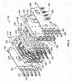
- FIG 2 is an exploded view of one of the contact modules 122 and part of the shield structure 126.
- the shield structure 126 includes a first ground shield 200 and a second ground shield 202.
- the first and second ground shields 200, 202 electrically connect the contact module 122 to the header shields 146 (shown in Figure 1 ).
- the first and second ground shields 200, 202 provide multiple, redundant points of contact to the header shield 146.
- the first and second ground shields 200, 202 provide shielding on all sides of the receptacle signal contacts 124.
- the contact module 122 includes a holder 214 having a first holder member 216 and a second holder member 218 that are coupled together to form the holder 214.
- the first and second holder members 216, 218 define a chamber 219 that receives receptacle signal contacts 124.
- the holder members 216, 218 are fabricated from an electrically conductive material.
- the holder members 216, 218 may be fabricated from a plastic material that has been metalized, plated or coated with a metallic layer.
- the holder members 216, 218 may be stamped and formed or may be die-cast from a metal material.
- the holder members 216, 218 may provide electrical shielding for the receptacle assembly 102.
- the holder members 216, 218 When the holder members 216, 218 are coupled together, the holder members 216, 218 define at least a portion of the shield structure 126 of the receptacle assembly 102.
- the ground shields 200, 202 are mechanically and electrically connected to the holder members 216, 218, respectively.
- the first and second holder members 216, 218 include first and second tabs 220, 221 extending inward toward one another from first and second walls 222, 223 of the holder members 216, 218, respectively.
- the tabs 220 define channels 224 therebetween.
- the tabs 221 define channels 225 therebetween.
- the tabs 220, 221 define at least a portion of the shield structure 126 of the receptacle assembly 102.
- the ground shields 200, 202 are attached to the first and second walls 222, 223, respectively.
- the holder members 216, 218 When assembled, the holder members 216, 218 are coupled together and define a front 226 and a bottom 228 of the holder 214.
- the holder members 216, 218 are mechanically and electrically connected at multiple, redundant points of contact within the contact module 122 to create a reliable electrical connection therebetween at regular intervals.
- the multiple points of contact at regular intervals reduce low frequency noise resonance effects to control near end and/or far end cross talk and improve signal performance.
- the intervals can be selected to reduce the noise in certain ranges or below a certain threshold. For example, the intervals may be selected to reduce noise resonance effects at below 12.5 GHz. The intervals may be selected to reduce noise resonance effects at higher frequency ranges if desired.
- the contact module 122 includes a frame assembly 230 held by the holder 214.
- the frame assembly 230 includes the receptacle signal contacts 124.
- the frame assembly 230 includes a pair of dielectric frames 240, 242 surrounding the receptacle signal contacts 124.
- the receptacle signal contacts 124 are initially held together as lead frames (not shown), which are overmolded with dielectric material to form the first and second dielectric frames 240, 242. Manufacturing processes other than overmolding a leadframe may be utilized to form the contact modules 122, such as loading receptacle signal contacts 124 into a formed dielectric body.
- the dielectric frame 240 includes a plurality of frame members 248. Each frame member 248 is formed around a different receptacle signal contact 124. Stated differently, each receptacle signal contact 124 extends along, and inside of, a corresponding frame member 248. The frame members 248 encase the receptacle signal contacts 124. The receptacle signal contacts 124 have mating portions 250 extending from the fronts and contact tails 252 extending from the bottoms of the frame members 248. Other configurations are possible in alternative embodiments. Inner portions or encased portions of the receptacle signal contacts 124 transition between the mating portions 250 and the contact tails 252 within the dielectric frame 240.
- the dielectric frame 240 includes a plurality of windows 254 extending through the dielectric frame 240 between the frame members 248.
- the windows 254 separate the frame members 248 from one another.
- the windows 254 extend entirely through the dielectric frame 240.
- the windows 254 are internal of the dielectric frame 240 and located between adjacent receptacle signal contacts 124, which are held in the frame members 248.
- the windows 254 extend along lengths of the receptacle signal contacts 124 between the contact tails 252 and the mating portions 250.
- the windows 254 may extend along a majority of the length of each receptacle signal contact 124 measured between the corresponding contact tail 252 and mating portion 250.
- first dielectric frame 240 and corresponding receptacle signal contacts 124 are coupled to the first holder member 216.
- the frame members 248 are received in corresponding channels 224.
- the first tabs 220 are received in corresponding windows 254 such that the tabs 220 are positioned between adjacent receptacle signal contacts 124.
- the tabs 220 provide electrical shielding between the receptacle signal contacts 124 on either side of the tabs 220.
- the second dielectric frame 242 is manufactured in a similar manner as the first dielectric frame 240 and includes similar components.
- the second dielectric frame 242 and corresponding receptacle signal contacts 124 are coupled to the second holder member 218 in a similar manner with the second tabs 221 extending through the windows 254 in the second dielectric frame 242.
- the receptacle signal contacts 124 are arranged as differential pairs.
- the tabs 220, 221 extend through the dielectric frames 240, 242 to provide shielding between the differential pairs of receptacle signal contacts 124.
- the first and second tabs 220, 221 have multiple points of contact therebetween to ensure electrical continuity of the shield structure 126 along the entire lengths of the receptacle signal contacts 124.
- the holder members 216, 218 provide shielding from electromagnetic interference (EMI) and/or radio frequency interference (RFI).
- EMI electromagnetic interference
- RFID radio frequency interference
- the holder members 216, 218 may provide shielding from other types of interference as well.
- the holder members 216, 218 provide shielding around the outside of the frames 240, 242 and thus around the outside of all of the receptacle signal contacts 124, such as between pairs of receptacle signal contacts 124, as well as between the receptacle signal contacts 124 using the tabs 220, 221 to control electrical characteristics, such as impedance control, cross-talk control, and the like, of the receptacle signal contacts 124.
- the first ground shield 200 includes a main body 260 configured to be coupled to the first wall 222 of the first holder member 216.
- the ground shield 200 includes grounding beams 262 extending forward from the main body 260.
- the grounding beams 262 are used to electrically connect the shield structure 126 to the corresponding header shield 146 (shown in Figure 1 ).
- the first ground shield 200 is manufactured from a metal material.
- the ground shield 200 is a stamped and formed part with the grounding beams 262 being stamped and formed out of plane with respect to the main body 260.
- the second ground shield 202 includes a main body 270 configured to be coupled to the second wall 223 of the second holder member 218.
- the ground shield 202 includes grounding beams 272 extending forward from the main body 270.
- the grounding beams 272 are used to electrically connect the shield structure 126 to the corresponding header shield 146 (shown in Figure 1 ).
- the second ground shield 202 is manufactured from a metal material.
- the ground shield 202 is a stamped and formed part with the grounding beams 272 being stamped and formed out of plane with respect to the main body 270.
- Figure 3 illustrates one of the contact modules 122 in an assembled state.
- the dielectric frames 240, 242 (shown in Figure 2 ) are received in the corresponding holder members 216, 218.
- the holder members 216, 218 are coupled together and generally surround the dielectric frames 240, 242.
- the receptacle signal contacts 124 are aligned with one another and define contact pairs 280.
- Each contact pair 280 is configured to transmit differential signals through the contact module 122.
- the first and second ground shields 200, 202 are coupled to the holder 214 to provide shielding for the receptacle signal contacts 124.
- the grounding beams 262, 272 extend along the receptacle signal contacts 124.
- the first and second ground shields 200, 202 are configured to be electrically connected to the header shields 146 (shown in Figure 1 ) when the receptacle assembly 102 is coupled to the header assembly 104 (shown in Figure 1 ).
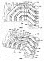
- Figure 4 is a side view of the first holder member 216 formed in accordance with an exemplary embodiment.
- Figure 5 is a perspective view of the first holder member 216.
- Figures 4 and 5 illustrate the first tabs 220 extending from the first wall 222 to define the corresponding channels 224.
- the first tabs 220 and channels 224 transition between the front 226 and bottom 228 of the first holder member 216.
- the first holder member 216 includes a plurality of connection features that mechanically and electrically connect the first holder member 216 to the second holder member 218 (shown in Figure 2 ).
- the multiple connection features create a reliable electrical connection between the first and second holder members 216, 218 to ensure that the shielding structure 126 is electrically commoned at regular intervals to reduce the ground induced noise resonances that can be present in pair-to-pair cross talk. Having multiple electrical connections reduces the presence of isolated ground structures around the receptacle signal contacts, which may enhance the electrical performance of the receptacle assembly 102 (shown in Figure 1 ).
- the first holder member 216 includes electrical radiation reducing features that reduce electrical radiation between channels 224.
- bridges 290 block any openings or gaps in the tabs 220 between channels 224.
- the bridges 290 may make the tabs 220 continuous from the front 226 to the bottom 228.
- Such electrical radiation reducing features reduce noise resonances between receptacle signal contacts 124 (shown in Figure 3 ) in adjacent channels 224 as compared to contact modules that have gaps, spaces or holes in the tabs that would allow electrical radiation therethrough.
- the electrical radiation reducing features improve performance of the contact module 122 (shown in Figure 3 ) as compared to contact modules that have gaps, spaces or holes in the tabs.
- connection features include first posts 300 arranged at intervals along the first tabs 220 and first holes 302 arranged at intervals along the first tabs 220.
- the intervals of the first posts 300 and first holes 302 may not be equidistant along any particular first tab 220 or from one tab 220 to another tab 220, but rather may be arranged at intervals that are less than a preselected maximum interval.
- the maximum interval is selected to reduce or eliminate frequency noise resonance effects in a particular frequency range or below a predetermined frequency, such as below 12.5 GHz. Having a shorter maximum interval generally increases the frequency below which frequency noise resonance effects are reduced. For example, further decreasing of the spacing between the connection features may reduce frequency noise resonance effects below 12.5 GHz, below 20 GHz, or below other targeted frequencies. Any desired frequency range may be targeted and the corresponding spacing between the connection features may be set accordingly.
- the first posts 300 are configured to be received in corresponding holes 322 (shown in Figure 7 ) in the second holder member 218 while the first holes 302 are configured to receive corresponding posts 320 (shown in Figure 7 ) extending from the second holder member 218, as described in further detailed below.
- the posts 300 and holes 302 may be arranged in any sequence, such as an alternating sequence of post-hole-post-hole along the first tab 220. Other sequences are possible in alternative embodiments.
- portions of the first tab 220 may be wider, such as along the bottom, and in such portions the posts 300 and holes 302 may be enlarged, which may allow the posts 300 to be more robust and reduce the risk of damage.
- the first tabs 220 may have different thickness along different sections thereof, with the thickness dimension generally defined across the tab 220 between the adjacent channels 224 on either side of the corresponding tab 220.
- the first holder member 216 may include only posts 300 or only holes 302.
- the first holder member 216 may include different sized and shaped posts 300 and holes 302 along the first tabs 220.
- the first holder member 216 may include connection features in locations other than along the first tabs 220.
- the first holder member 216 includes outer posts 304 along surfaces of the first holder member 216 outside of the area of the first tabs 220.
- connection features include first shoulders 306 along the first tabs 220.
- Each first shoulder 306 may be provided along the upper half of the corresponding first tab 220 and include a downward facing surface 308 that is configured to engage a corresponding shoulder of the second holder member 218.
- the first shoulders 306 may engage the second holder member 218 to create mechanical and/or electrical connection between the first holder member 216 and the second holder member 218.
- the first posts 300 have an outer perimeter 310.
- the first posts 300 may be oblong or oval in shape.
- the first posts 300 may have other shapes, such as circular, rectangular or other shapes.
- the first posts 300 may be elongated along the length of the tab 220, with the length of the tab 220 being defined in a direction generally parallel to the channels 224.
- the posts 300 may be tapered.
- each post 300 may be wider at a base 312 of the post 300 and narrower at a tip 314 of the post 300.
- the posts 300 may have chamfered lead-ins 316 at the tip 314 to help guide the posts 300 into the corresponding holes 322.
- Figure 6 illustrates a portion of the first holder member 216 showing one of the first posts 300 and one of the first holes 302.
- the second posts 320 and second holes 322 may be similar to the first posts 300 and first holes 302, respectively.
- the first tabs 220 extend inward from the first wall 222 to an inner edge 330.
- the first shoulders 306 extend from the inner edge 330.
- the first post 300 extends from the inner edge 330.
- the first post 300 has an oval cross section. However, other shapes are possible in alternative embodiments.
- the first post 300 is sized and shaped to fit in the corresponding second hole 322 when the first holder member 216 is coupled to the second holder member 218 (shown in Figure 7 ).
- the first post 300 is an integral part of the first holder member 216 and may be co-molded or co-formed with other portions of the first holder member 216, such as the first tab 220 and the first wall 222.
- the first hole 302 is sized and shaped to receive one of the second posts 320 (shown in Figure 7 ).
- the first hole 302 is generally hexagonally shaped bounded by a plurality of flat walls 332; however other polygonal shaped holes may be used in alternative embodiments having a different number of flat walls 332.
- the first hole 302 includes undercuts 334 at opposite sides 336, 338 of the first hole 302.
- the undercuts 334 are aligned along a longitudinal axis 340 of the first hole 302, which generally runs along the length of the first tab 220, such as parallel to the channels 224.
- the undercuts 334 provide void spaces for the first hole 302.
- the second post 320 when the second post 320 is loaded in the corresponding first hole 302, the second post 320 may be compressed and the undercuts 334 provide a space for the second post 320 to swell into, which may relieve pressure or stress in the second post 320, such as to reduce the risk of damage to the second post 320 or to the first tab 220.
- Interference tabs 342 are defined at the intersections between the flat walls 332 and the undercuts 334.
- the interference tabs 342 are configured to engage the second post 320 received in the first hole 302.
- the interference tabs 342 define termination points 344 between the first holder member 216 and the second holder member 218 (shown in Figure 7 ).
- Each second post 320 is configured to engage the first holder member 216 at a plurality of termination points 344 ensuring good electrical connection between the first holder member 216 and the second holder member 218.
- the first hole 302 is entirely contained within and bounded by the material of the first tab 220.
- the first hole 302 includes the bridges 290 closing or blocking the first hole 302 from the channels 224 on either side of the first hole 302.
- the first hole 302 does not include any open sides that open to the channels 224.
- the bridges 290 extend across the first hole 302 between tab segments 346, 348 defined on opposite sides of the first hole 302.
- the bridges 290 define a continuous shield structure along the first tab 220, such as from the tab segment 346 to the tab segment 348.
- the bridges 290 block electrical radiation from propagating across the first hole 302 between the adjacent channels 224 (for example, as compared to a situation having the first hole 302 with open sides rather than the bridges 290, where such open sides could allow electrical radiation leakage across the first hole 302 from one channel 224 to the other channel 224).
- the bridges 290 have inner edges 350, which may be coplanar with the inner edge 330 of the first tab 220.
- the bridges 290 and associated tab segments 346, 348 form continuous walls extending across the first hole 302 that define the channels 224 on opposite sides of the first tab 220.
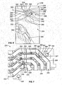
- Figure 7 is a side view of the second holder member 218 formed in accordance with an exemplary embodiment.
- Figure 7 illustrates the second tabs 221 extending from the second wall 223 to define the corresponding channels 225.
- the second holder member 218 includes a plurality of connection features that mechanically and electrically connect the second holder member 218 to the first holder member 216 (shown in Figures 4 and 5 ).
- the multiple connection features create a reliable electrical connection between the first and second holder members 216, 218 to ensure that the shielding structure is electrically commoned at regular intervals to reduce the ground induced noise resonances that can be present in pair-to-pair cross talk. Having multiple electrical connections reduces the presence of isolated ground structures around the receptacle signal contacts, which may enhance the electrical performance of the receptacle assembly 102 (shown in Figure 1 ).
- the second holder member 218 includes electrical radiation reducing features that reduce electrical radiation between the adjacent channels 225.
- bridges 292 block any openings or gaps in the tabs 221 between the adjacent channels 225.
- the bridges 292 may make the tabs 221 continuous from the front 226 to the bottom 228.
- Such electrical radiation reducing features reduce noise resonances between receptacle signal contacts 124 (shown in Figure 3 ) in adjacent channels 225 as compared to contact modules that have gaps, spaces or holes in the tabs that would allow electrical radiation therethrough.
- the electrical radiation reducing features improve performance of the contact module 122 (shown in Figure 3 ) as compared to contact modules that have gaps, spaces or holes in the tabs.
- connection features include second posts 320 arranged at intervals along the second tabs 221 and second holes 322 arranged at intervals along the second tabs 221.
- the intervals may be selected to reduce or eliminate frequency noise resonance effects in a particular frequency range or below a predetermined frequency, such as below 12.5 GHz. Any desired frequency range may be targeted and the corresponding spacing between the connection features may be set accordingly.
- the second posts 320 are configured to be received in corresponding first holes 302 (shown in Figures 4 and 5 ) in the first holder member 216 while the second holes 322 are configured to receive corresponding posts 300 (shown in Figures 4 and 5 ) extending from the first holder member 216.
- the posts 320 and holes 322 may be arranged in any sequence, such as an alternating sequence of post-hole-post-hole along the second tab 221. Other sequences are possible in alternative embodiments.
- the posts 320 and holes 322 in such region(s) may be enlarged, which may allow the posts 320 to be more robust and reduce the risk of damage.
- the second holder member 218 may include only posts 320 or only holes 322.
- the second holder member 218 may include different sized and shaped posts 320 and holes 322 along the second tabs 221.
- the second holder member 218 may include connection features in locations other than along the second tabs 221.
- the second holder member 218 includes outer holes 324 along surfaces of the second holder member 218 outside of the area of the second tabs 221. The outer holes 324 are configured to receive the outer posts 304 (shown in Figures 4 and 5 ) of the first holder member 216.
- connection features include second shoulders 326 along the second tabs 221.
- Each second shoulder 326 may be provided along the lower half of the corresponding second tab 221 and include an upward facing surface 328 that is configured to engage a corresponding first shoulder 306 (shown in Figures 4 and 5 ) of the first holder member 216.
- the second shoulders 326 may engage the first shoulders 306 to create mechanical and/or electrical connection between the first holder member 216 and the second holder member 218.
- the second tabs 221 may have different thickness along different sections thereof, with the thickness dimension generally defined across the tab 221 between the adjacent channels 225 on either side of the corresponding tab 221.
- the second posts 320 may have post thicknesses approximately equal to the corresponding tab thicknesses.
- the second posts 320 may be may be oblong or oval in shape.
- the second posts 320 may have other shapes, such as circular, rectangular or other shapes.
- the second posts 320 may be elongated along the length of the tab 221, with the length of the tab 221 being defined in a direction generally parallel to the channels 225.
- the second posts 320 may be tapered.
- each post 320 may be wider at the base of the post 320 and narrower at the tip of the post 320.
- the posts 320 may have chamfered lead-ins at the tip to help guide the posts 320 into the corresponding holes 302 in the first holder member 216 (shown in Figures 4 and 5 ).
- the second tabs 221 extend inward from the second wall 223 to an inner edge 360.
- the second post 320 extends from the inner edge 360.
- the second post 320 has an oval cross section; however, other shapes are possible in alternative embodiments.
- the second post 320 is sized and shaped to fit in the corresponding first hole 302 when the first holder member 216 is coupled to the second holder member 218.
- the second post 320 is similar to the first post 300 and like components may be identified with like reference numbers.
- the second hole 322 is sized and shaped to receive one of the first posts 300.
- the second hole 322 is similar to the first hole 302 and like components may be identified with like reference numbers.
- the second hole 322 is bounded by a plurality of the flat walls 332 and includes undercuts 334.
- the interference tabs 342 define multiple termination points 344 for mechanical and electrical connection to the first post 300.
- the bridges 292 extend across the sides of the second holes 322 to close off the second holes 322 from the adjacent channels 225.
- the bridges 292 define continuous walls with tab segments 362, 364 of the second tab 221 arranged on opposite sides of the second hole 322. The bridges 292 block electrical radiation across the second hole 322 between the adjacent channels 225.
- Figure 8 is a schematic illustration of the first post 300 positioned relative to the second hole 322 showing interference between the first post 300 and the second hole 322 due to size and shape differences between the first post 300 and the second hole 322.
- the shaded regions 370 represent the overlap or interference at the interference tabs 342.
- the oblong shape of the first post 300 positions portions of the outer perimeter 310 of the first post 300 beyond the flat walls 332. As the tip 314 of the first post 300 is loaded into the second hole 322, the first post 300 engages the interference tabs 342 and portions of the first post 300 and/or portions of the interference tabs 342 are compressed, creating an interference fit between the first post 300 and the interference tabs 342.
- the shape of the first post 300 changes and portions of the first post 300 may swell into the undercuts 334 (indicated by the dashed lines showing the changed shapes of the first post 300 and the interference tabs 342).
- the undercuts 334 are void spaces that accommodate the swollen first post 300.
- the second hole 322 may include gaps 372 between the outer perimeter 310 of the first post 300 and the bridges 292. Portions of the first post 300 may swell into the gaps 372.
- the gaps 372 are void spaces that accommodate the swollen first post 300.
- Figure 9 is a side view of a portion of the contact module 122 showing the first post 300 loaded into the corresponding second hole 322.
- the second hole 322 includes a counterbore 380 at an outer end or rear 382 of the second hole 322.
- the rear 382 is generally opposite the inner edge 360 (shown in Figure 7 ).
- the rear 382 may be at the second wall 223 and the counterbore 380 may be formed in the exterior of the second wall 223.
- the counterbore 380 provides a relief area for the first post 300 to swell and/or return to its normal shape.
- the counterbore 380 is shaped differently than the second hole 322 and, when the first post 300 swells and/or returns to the normal shape, the first post 300 may be mechanically secured in the second holder member 218 due to interference with portions of the second holder member 218, such as the interference tabs 342 (shown in Figure 8 ).
- Figure 10 is a cross sectional view of a portion of the contact module 122 showing the first post 300 in the second hole 322.
- the tip 314 of the first post 300 is in the counterbore 380.
- the bridges 292 are shown extending to the first holder member 216.
- the bridges 292 form continuous walls between the circuits or data channels defined by the receptacle signal contacts 124. For example, even if the first post 300 were to break off, there is shield structure, namely the bridges 292 between the channels 225.
- the second holes 322 are not open to both channels 225, but rather are covered by the bridges 292 which extend across the second holes 322.
- Figure 11 is a side view of a first holder member 416 formed in accordance with an exemplary embodiment and configured to be mated with a second holder member 418 (shown in Figure 13).
- Figure 12 is a perspective view of the first holder member 416.
- the first holder member 416 may be similar to the first holder member 216 (shown in Figures 4 and 5 ) and some components of the first holder member 416 are not described in detail as they were described above with reference to the first holder member 216.
- the first holder member 416 includes first tabs 420 extending from a first wall 422 to define corresponding channels 424.
- the first holder member 416 includes a plurality of connection features that mechanically and electrically connect the first holder member 416 to the second holder member 418 (shown in Figure 13 ).
- the first holder member 416 forms part of a shielding structure for the frame assembly 230 (shown in Figure 2 ).
- the first holder member 416 includes electrical radiation reducing features that reduce electrical radiation between the channels 424.
- bridges 490 block any openings or gaps in the tabs 420 between channels 424. The bridges 490 may make the tabs 420 continuous such that there are no openings between the channels 424.
- connection features include first posts 500 and first holes 502 arranged at intervals along the first tabs 420.
- the first posts 500 are configured to be received in corresponding holes 522 (shown in Figure 13 ) in the second holder member 418 while the first holes 502 are configured to receive corresponding posts 520 (shown in Figure 13 ) extending from the second holder member 418.
- the posts 500 and holes 502 are aligned with each other at the same location along the first tabs 420.
- the first posts 500 are half-posts and the first holes 502 are half-holes.
- the first tabs 420 extend inward from the first wall 422 to an inner edge 530.
- the first post 500 extends from the inner edge 530.
- the first post 500 is sized and shaped to fit in the corresponding second hole 522 when the first holder member 416 is coupled to the second holder member 418 (shown in Figure 13 ).
- the first posts 500 have an outer perimeter 510 and a flat mating wall 512 that faces the first hole 502.
- the first posts 500 are semi-circular in shape; however, the first posts 500 may have other shapes.
- the flat mating walls 512 may extend generally parallel to the channels 424 on opposite sides of the first posts 500.
- the posts 500 may be tapered and may include chamfered lead-ins 514 to the outer perimeter 510 and/or a chamfered lead-in 516 to the flat mating wall 512.
- the first post 500 defines the bridge 490 extending across the corresponding first hole 502.
- the flat mating wall 512 may span entirely across the first hole 502 between the opposite tab segments on opposite sides of the first hole 502.
- the first hole 502 is sized and shaped to receive one of the second posts 520 (shown in Figure 13 ).
- the first hole 502 is semi-hexagonal shaped bounded by a plurality of flat walls 532 and bounded by the flat mating wall 512 of the first post 500; however other polygonal shaped holes may be used in alternative embodiments having a different number of flat walls 532.
- the first hole 502 may be semi-circular in shape also being bounded by the flat mating wall 512.
- the flat walls 532 are configured to engage the second post 520 received in the first hole 502.
- the flat walls 532 define termination points between the first holder member 416 and the second holder member 418 (shown in Figure 13 ).
- the first hole 502 is open to one of the channels 424, however the other channel 424 is blocked by the corresponding bridge 490 defined by the associated first post 500.
- the bridge 490 closes or blocks the first hole 502 from one of the channels 424, thus defining a continuous ground circuit or shield structure between the channels 424.
- the first tabs 420 do not include any openings or gaps between the channels 424.
- the bridges 490 extend across the first holes 502 between tab segments 534, 536 defined on opposite sides of the first holes 502.
- the bridges 490 define continuous shield structures along the first tabs 420, such as from the tab segments 534 to the associated tab segments 536.
- the bridges 490 block electrical radiation from propagating across the first holes 502 between the adjacent channels 424.
- Figure 13 is a side view of the second holder member 418 formed in accordance with an exemplary embodiment.
- Figure 13 illustrates second tabs 421 extending from a second wall 423 to define the corresponding channels 425.
- the second holder member 418 may be similar to the second holder member 218 (shown in Figure 7 ) and some components of the second holder member 418 are not described in detail as they were described above with reference to the second holder member 218.
- the second holder member 418 includes electrical radiation reducing features that reduce electrical radiation between the adjacent channels 425.
- bridges 492 block any openings or gaps in the tabs 421 between the adjacent channels 425.
- the bridges 492 may make the tabs 421 continuous such that there are no openings between the channels 425.
- connection features include second posts 520 and second holes 522 arranged at intervals along the second tabs 421.
- the second posts 520 are configured to be received in corresponding first holes 502 (shown in Figures 11 and 12 ) in the first holder member 416 while the second holes 522 are configured to receive corresponding posts 500 (shown in Figures 11 and 12 ) extending from the first holder member 416.
- the posts 520 and holes 522 are aligned with each other at the same location along the second tabs 421.
- the second posts 520 are half-posts and the second holes 522 are half-holes.
- the second tabs 421 extend inward from the second wall 423 to an inner edge 538.
- the second post 520 extends from the inner edge 538.
- the second post 520 is sized and shaped to fit in the corresponding first hole 502 when the second holder member 418 is coupled to the first holder member 416 (shown in Figures 11 and 12 ).
- the second posts 520 have an outer perimeter 540 and a flat mating wall 542 that faces the second hole 522.
- the second posts 520 are semi-circular in shape; however, the second posts 520 may have other shapes.
- the flat mating walls 542 may extend generally parallel to the channels 525 on opposite sides of the second posts 520.
- the second posts 520 may be tapered and may include chamfered lead-ins 544 to the outer perimeter 540 and/or a chamfered lead-in 546 to the flat mating wall 542.
- the second post 520 defines the bridge 492 extending across the corresponding second hole 522.
- the flat mating wall 542 may span entirely across the second hole 522 between tab segments 556, 558 on opposite sides of the second hole 522.
- the second hole 522 is sized and shaped to receive one of the first posts 500 (shown in Figures 11 and 12 ).
- the second hole 522 is semi-hexagonal shaped bounded by a plurality of flat walls 552 and bounded by the flat mating wall 542 of the second post 520; however other polygonal shaped holes may be used in alternative embodiments having a different number of flat walls 552.
- the second hole 522 may be semi-circular in shape also being bounded by the flat mating wall 542.
- the flat walls 552 are configured to engage the first post 500 received in the second hole 522.
- the flat walls 552 define termination points between the first holder member 416 and the second holder member 418.
- the second hole 522 is open to one of the channels 425, however the other channel 425 is blocked by the corresponding bridge 492 defined by the associated second post 520.
- the bridge 492 closes or blocks the second hole 522 from one of the channels 425, thus defining a continuous ground circuit or shield structure between the channels 425.
- the second tabs 421 do not include any openings or gaps between the channels 425.
- the bridges 492 extend across the second holes 522 between the tab segments 556, 558 defined on opposite sides of the second holes 522.
- the bridges 492 define continuous shield structures along the second tabs 421, such as from the tab segments 556 to corresponding tab segments 558.
- the bridges 492 block electrical radiation from propagating across the second holes 522 between the adjacent channels 425.
- Figure 14 is a schematic illustration of the first post 500 positioned relative to the second hole 522 showing interference between the first post 500 and the second hole 522 due to size and shape differences between the first post 500 and the second hole 522. Shaded regions 570 represent overlap between the first post 500 and the second hole 522.
- the shape of the second hole 522 forces the first post 500 against the second post 520.
- the flat mating wall 512 of the first post 500 is pressed against the flat mating wall 542 of the second post 520.
- the flat walls 552 are angled to press the first post 500 against the second post 520.
- the first post 500 and/or portions of the walls 552 may be compressed, creating an interference fit between the first post 500 and the second tab 421.
- Figure 15 is a cross sectional view of a portion of the contact module 122 showing the first post 500 in the second hole 522 and the second post 520 in the first hole 502.
- the flat mating walls 512, 542 are electrically connected together.
- the flat mating walls 512, 542 define the bridges 490, 492, respectively.
- the bridges 490, 492 form continuous walls between the circuits or data channels defined by the receptacle signal contacts 124. For example, even if one of the posts 500, 520 were to break off, there is shield structure, namely the bridge 490 or 492 of the other post 500, 520 between the channels 425.
Landscapes
- Details Of Connecting Devices For Male And Female Coupling (AREA)
Abstract
Description
- The invention relates to a connector assembly having a shielding structure with a plurality of termination points.
- Some electrical systems utilize electrical connectors to interconnect two circuit boards, such as a motherboard and daughtercard. In some systems, to electrically connect the electrical connectors, a midplane circuit board is provided with front and rear header connectors on opposite front and rear sides of the midplane circuit board. Other systems electrically connect the circuit boards without the use of a midplane circuit board by directly connecting electrical connectors on the circuit boards.
- However, as speed and performance demands increase, known electrical connectors are proving to be insufficient. Signal loss and/or signal degradation is a problem in known electrical systems. Additionally, there is a desire to increase the density of electrical connectors to increase throughput of the electrical system, without an appreciable increase in size of the electrical connectors, and in some cases, with a decrease in size of the electrical connectors. Such increase in density and/or reduction in size causes further strains on performance.
- In order to address performance, some known systems utilize shielding to reduce interference between the contacts of the electrical connectors. However, the shielding utilized in known systems is not without disadvantages. For instance, the shielding along the signal channels may be subject to ground induced noise resonances, particularly at higher frequencies. In the presence of isolated ground structures, such ground induced noise resonances lead to pair-to-pair crosstalk.
- A need remains for a connector assembly that provides efficient shielding to meet particular performance demands.
- This problem is solved by a connector assembly according to claim 1.
- According to the invention, a connector assembly comprises a contact module comprising a conductive holder and a frame assembly held by the conductive holder. The conductive holder comprises a first holder member and second holder member coupled to the first holder member. The first and second holder members are electrically connected to each other. The conductive holder has a chamber between the first and second holder members. The chamber is divided into a plurality of channels by first tabs of the first holder member and second tabs of the second holder member. The frame assembly comprises at least one dielectric frame disposed in the chamber. The at least one dielectric frame comprises a plurality of contacts and frame members supporting the contacts. The contacts are routed through corresponding channels. The first and second tabs are disposed between corresponding frame members. The first tabs have posts extending therefrom, and the second tabs have holes receiving the posts. The second tabs have tab segments on opposite sides of the associated holes. Each of the holes has a bridge extending across the hole between the tab segments on opposite sides of the hole. The bridge blocks electrical radiation across the hole between the adjacent channels.
- The invention will now be described by way of example with reference to the accompanying drawings wherein:
-
Figure 1 is a perspective view of an exemplary embodiment of an electrical connector system illustrating a connector assembly and a header assembly. -
Figure 2 is an exploded view of one of the contact modules and part of a shield structure shown inFigure 1 . -
Figure 3 illustrates one of the contact modules in an assembled state. -
Figure 4 is a side view of a holder member of the contact module formed in accordance with an exemplary embodiment. -
Figure 5 is a perspective view of the holder member. -
Figure 6 illustrates a portion of the holder member shown inFigure 4 . -
Figure 7 is a side view of another holder member formed in accordance with an exemplary embodiment. -
Figure 8 is a schematic illustration of the holder members being coupled together. -
Figure 9 is a side view of a portion of the contact module showing the holder members coupled together. -
Figure 10 is a cross sectional view of a portion of the contact module showing the holder members being coupled together. -
Figure 11 is a side view of a holder member formed in accordance with an exemplary embodiment. -
Figure 12 is a perspective view of the holder member shown inFigure 11 . -
Figure 13 is a side view of a holder member formed in accordance with an exemplary embodiment. -
Figure 14 is a schematic illustration of the of the holder members shown inFigures 11-13 being coupled together. -
Figure 15 is a cross sectional view of a portion of the contact module showing the holder members shown inFigures 11-13 coupled together. -
Figure 1 is a perspective view of an exemplary embodiment of anelectrical connector system 100 illustrating areceptacle assembly 102 and aheader assembly 104 that may be directly mated together. Thereceptacle assembly 102 and/or theheader assembly 104 may be referred to hereinafter individually as a "connector assembly" or collectively as "connector assemblies". Other types of connector assemblies may be used in alternative embodiments other than a receptacle assembly or a header assembly. The receptacle andheader assemblies respective circuit boards - The receptacle and
header assemblies mating axis 110. The receptacle andheader assemblies circuit boards circuit boards circuit boards - The
receptacle assembly 102 includes afront housing 120 that holds a plurality ofcontact modules 122. Any number ofcontact modules 122 may be provided to increase the number of data channels between thecircuit boards contact modules 122 each include a plurality of receptacle signal contacts 124 (shown inFigure 2 ) that are received in thefront housing 120 for mating with theheader assembly 104. - In an exemplary embodiment, each
contact module 122 has ashield structure 126 for providing electrical shielding for thereceptacle signal contacts 124. In an exemplary embodiment, theshield structure 126 is electrically connected to theheader assembly 104 and/or thecircuit board 106. For example, theshield structure 126 may be electrically connected to theheader assembly 104 by extensions (e.g. beams or fingers) extending from thecontact modules 122 that engage theheader assembly 104. Theshield structure 126 may be electrically connected to thecircuit board 106 by features, such as ground pins. Theshield structure 126 may provide shielding along substantially the entire length of the data channels between thecircuit boards - The
receptacle assembly 102 includes amating end 128 and amounting end 130. Thereceptacle signal contacts 124 are received in thefront housing 120 and held therein at themating end 128 for mating to theheader assembly 104. Thereceptacle signal contacts 124 are arranged in a matrix of rows and columns. Any number ofreceptacle signal contacts 124 may be provided in the rows and columns. Thereceptacle signal contacts 124 also extend to themounting end 130 for mounting to thecircuit board 106. Optionally, themounting end 130 may be substantially perpendicular to themating end 128. - The
front housing 120 includes a plurality ofsignal contact openings 132 and a plurality ofground contact openings 134 at themating end 128. Thereceptacle signal contacts 124 are aligned with correspondingsignal contact openings 132 for mating with correspondingheader signal contacts 144 when the receptacle andheader assemblies ground contact openings 134 receive header shields 146 therein when the receptacle andheader assemblies shield structures 126 of thecontact modules 122 are electrically connected with the header shields 146 to electrically common the receptacle andheader assemblies - The
front housing 120 is manufactured from a dielectric material, such as a plastic material, and provides isolation between thesignal contacts shield structure 126. Thefront housing 120 isolates each set of receptacle andheader signal contacts - The
header assembly 104 includes aheader housing 138 havingwalls 140 defining achamber 142. Theheader assembly 104 has amating end 150 and a mountingend 152 that is mounted to thecircuit board 108. Optionally, the mountingend 152 may be substantially parallel to themating end 150. Thereceptacle assembly 102 is received in thechamber 142 through themating end 150. Thefront housing 120 engages thewalls 140 to hold thereceptacle assembly 102 in thechamber 142. Theheader signal contacts 144 and the header shields 146 extend from abase wall 148 into thechamber 142. Theheader signal contacts 144 and the header shields 146 extend through thebase wall 148 and are mounted to thecircuit board 108. - In an exemplary embodiment, the
header signal contacts 144 are arranged as differential pairs. The header shields 146 are positioned between the differential pairs to provide electrical shielding between adjacent differential pairs. In the illustrated embodiment, the header shields 146 are C-shaped and provide shielding on three sides of the corresponding pair ofheader signal contacts 144. The header shields 146 have a plurality of walls, such as threeplanar walls walls wall 156 defines a center wall or top wall of the header shields 146. Thewalls center wall 156. The header shield 146 associated with another pair ofheader signal contacts 144 provides shielding along the open, fourth side of the header shield 146 such that each of the pairs ofsignal contacts 144 is shielded from each adjacent pair in the same column and the same row. Other configurations or shapes for the header shields 146 are possible in alternative embodiments. More or less walls may be provided in alternative embodiments. The walls may be bent or angled rather than being planar. In other alternative embodiments, the header shields 146 may provide shielding forindividual signal contacts 144 or sets of contacts having more than twosignal contacts 144. -
Figure 2 is an exploded view of one of thecontact modules 122 and part of theshield structure 126. Theshield structure 126 includes afirst ground shield 200 and asecond ground shield 202. The first and second ground shields 200, 202 electrically connect thecontact module 122 to the header shields 146 (shown inFigure 1 ). The first and second ground shields 200, 202 provide multiple, redundant points of contact to the header shield 146. The first and second ground shields 200, 202 provide shielding on all sides of thereceptacle signal contacts 124. - The
contact module 122 includes aholder 214 having afirst holder member 216 and asecond holder member 218 that are coupled together to form theholder 214. When theholder members second holder members chamber 219 that receivesreceptacle signal contacts 124. Theholder members holder members holder members holder members holder members receptacle assembly 102. When theholder members holder members shield structure 126 of thereceptacle assembly 102. The ground shields 200, 202 are mechanically and electrically connected to theholder members - The first and
second holder members second tabs second walls holder members tabs 220 definechannels 224 therebetween. Thetabs 221 definechannels 225 therebetween. Thetabs shield structure 126 of thereceptacle assembly 102. The ground shields 200, 202 are attached to the first andsecond walls - When assembled, the
holder members bottom 228 of theholder 214. Theholder members contact module 122 to create a reliable electrical connection therebetween at regular intervals. The multiple points of contact at regular intervals reduce low frequency noise resonance effects to control near end and/or far end cross talk and improve signal performance. The intervals can be selected to reduce the noise in certain ranges or below a certain threshold. For example, the intervals may be selected to reduce noise resonance effects at below 12.5 GHz. The intervals may be selected to reduce noise resonance effects at higher frequency ranges if desired. - The
contact module 122 includes aframe assembly 230 held by theholder 214. Theframe assembly 230 includes thereceptacle signal contacts 124. Theframe assembly 230 includes a pair ofdielectric frames receptacle signal contacts 124. In an exemplary embodiment, thereceptacle signal contacts 124 are initially held together as lead frames (not shown), which are overmolded with dielectric material to form the first and second dielectric frames 240, 242. Manufacturing processes other than overmolding a leadframe may be utilized to form thecontact modules 122, such as loadingreceptacle signal contacts 124 into a formed dielectric body. - The
dielectric frame 240 includes a plurality offrame members 248. Eachframe member 248 is formed around a differentreceptacle signal contact 124. Stated differently, eachreceptacle signal contact 124 extends along, and inside of, acorresponding frame member 248. Theframe members 248 encase thereceptacle signal contacts 124. Thereceptacle signal contacts 124 havemating portions 250 extending from the fronts and contacttails 252 extending from the bottoms of theframe members 248. Other configurations are possible in alternative embodiments. Inner portions or encased portions of thereceptacle signal contacts 124 transition between themating portions 250 and thecontact tails 252 within thedielectric frame 240. - The
dielectric frame 240 includes a plurality ofwindows 254 extending through thedielectric frame 240 between theframe members 248. Thewindows 254 separate theframe members 248 from one another. In an exemplary embodiment, thewindows 254 extend entirely through thedielectric frame 240. Thewindows 254 are internal of thedielectric frame 240 and located between adjacentreceptacle signal contacts 124, which are held in theframe members 248. Thewindows 254 extend along lengths of thereceptacle signal contacts 124 between thecontact tails 252 and themating portions 250. Optionally, thewindows 254 may extend along a majority of the length of eachreceptacle signal contact 124 measured between thecorresponding contact tail 252 andmating portion 250. - During assembly, the first
dielectric frame 240 and correspondingreceptacle signal contacts 124 are coupled to thefirst holder member 216. Theframe members 248 are received in correspondingchannels 224. Thefirst tabs 220 are received in correspondingwindows 254 such that thetabs 220 are positioned between adjacentreceptacle signal contacts 124. Thetabs 220 provide electrical shielding between thereceptacle signal contacts 124 on either side of thetabs 220. - The second
dielectric frame 242 is manufactured in a similar manner as the firstdielectric frame 240 and includes similar components. The seconddielectric frame 242 and correspondingreceptacle signal contacts 124 are coupled to thesecond holder member 218 in a similar manner with thesecond tabs 221 extending through thewindows 254 in the seconddielectric frame 242. When the first and second dielectric frames 240, 242 are arranged in theholder members receptacle signal contacts 124 are arranged as differential pairs. Thetabs dielectric frames receptacle signal contacts 124. The first andsecond tabs shield structure 126 along the entire lengths of thereceptacle signal contacts 124. - The
holder members shield structure 126, provide electrical shielding between and around respective receptacle signalcontacts 124. Theholder members holder members holder members frames receptacle signal contacts 124, such as between pairs ofreceptacle signal contacts 124, as well as between thereceptacle signal contacts 124 using thetabs receptacle signal contacts 124. - The
first ground shield 200 includes amain body 260 configured to be coupled to thefirst wall 222 of thefirst holder member 216. Theground shield 200 includes groundingbeams 262 extending forward from themain body 260. The grounding beams 262 are used to electrically connect theshield structure 126 to the corresponding header shield 146 (shown inFigure 1 ). In an exemplary embodiment, thefirst ground shield 200 is manufactured from a metal material. Theground shield 200 is a stamped and formed part with the grounding beams 262 being stamped and formed out of plane with respect to themain body 260. - The
second ground shield 202 includes amain body 270 configured to be coupled to thesecond wall 223 of thesecond holder member 218. Theground shield 202 includes groundingbeams 272 extending forward from themain body 270. The grounding beams 272 are used to electrically connect theshield structure 126 to the corresponding header shield 146 (shown inFigure 1 ). In an exemplary embodiment, thesecond ground shield 202 is manufactured from a metal material. Theground shield 202 is a stamped and formed part with the grounding beams 272 being stamped and formed out of plane with respect to themain body 270. -
Figure 3 illustrates one of thecontact modules 122 in an assembled state. During assembly of thecontact module 122, the dielectric frames 240, 242 (shown inFigure 2 ) are received in thecorresponding holder members holder members dielectric frames dielectric frames holder 214, thereceptacle signal contacts 124 are aligned with one another and define contact pairs 280. Eachcontact pair 280 is configured to transmit differential signals through thecontact module 122. - The first and second ground shields 200, 202 (
second ground shield 202 being shown inFigure 2 ) are coupled to theholder 214 to provide shielding for thereceptacle signal contacts 124. The grounding beams 262, 272 extend along thereceptacle signal contacts 124. The first and second ground shields 200, 202 are configured to be electrically connected to the header shields 146 (shown inFigure 1 ) when thereceptacle assembly 102 is coupled to the header assembly 104 (shown inFigure 1 ). -
Figure 4 is a side view of thefirst holder member 216 formed in accordance with an exemplary embodiment.Figure 5 is a perspective view of thefirst holder member 216.Figures 4 and 5 illustrate thefirst tabs 220 extending from thefirst wall 222 to define the correspondingchannels 224. Thefirst tabs 220 andchannels 224 transition between the front 226 andbottom 228 of thefirst holder member 216. - In an exemplary embodiment, the
first holder member 216 includes a plurality of connection features that mechanically and electrically connect thefirst holder member 216 to the second holder member 218 (shown inFigure 2 ). The multiple connection features create a reliable electrical connection between the first andsecond holder members structure 126 is electrically commoned at regular intervals to reduce the ground induced noise resonances that can be present in pair-to-pair cross talk. Having multiple electrical connections reduces the presence of isolated ground structures around the receptacle signal contacts, which may enhance the electrical performance of the receptacle assembly 102 (shown inFigure 1 ). Additionally, thefirst holder member 216 includes electrical radiation reducing features that reduce electrical radiation betweenchannels 224. For example, bridges 290 block any openings or gaps in thetabs 220 betweenchannels 224. Thebridges 290 may make thetabs 220 continuous from the front 226 to the bottom 228. Such electrical radiation reducing features reduce noise resonances between receptacle signal contacts 124 (shown inFigure 3 ) inadjacent channels 224 as compared to contact modules that have gaps, spaces or holes in the tabs that would allow electrical radiation therethrough. As such, the electrical radiation reducing features improve performance of the contact module 122 (shown inFigure 3 ) as compared to contact modules that have gaps, spaces or holes in the tabs. - In an exemplary embodiment, the connection features include
first posts 300 arranged at intervals along thefirst tabs 220 andfirst holes 302 arranged at intervals along thefirst tabs 220. The intervals of thefirst posts 300 andfirst holes 302 may not be equidistant along any particularfirst tab 220 or from onetab 220 to anothertab 220, but rather may be arranged at intervals that are less than a preselected maximum interval. The maximum interval is selected to reduce or eliminate frequency noise resonance effects in a particular frequency range or below a predetermined frequency, such as below 12.5 GHz. Having a shorter maximum interval generally increases the frequency below which frequency noise resonance effects are reduced. For example, further decreasing of the spacing between the connection features may reduce frequency noise resonance effects below 12.5 GHz, below 20 GHz, or below other targeted frequencies. Any desired frequency range may be targeted and the corresponding spacing between the connection features may be set accordingly. - The
first posts 300 are configured to be received in corresponding holes 322 (shown inFigure 7 ) in thesecond holder member 218 while thefirst holes 302 are configured to receive corresponding posts 320 (shown inFigure 7 ) extending from thesecond holder member 218, as described in further detailed below. Theposts 300 andholes 302 may be arranged in any sequence, such as an alternating sequence of post-hole-post-hole along thefirst tab 220. Other sequences are possible in alternative embodiments. Optionally, portions of thefirst tab 220 may be wider, such as along the bottom, and in such portions theposts 300 andholes 302 may be enlarged, which may allow theposts 300 to be more robust and reduce the risk of damage. For example, thefirst tabs 220 may have different thickness along different sections thereof, with the thickness dimension generally defined across thetab 220 between theadjacent channels 224 on either side of thecorresponding tab 220. - Optionally, in an alternative embodiment, the
first holder member 216 may include only posts 300 or only holes 302. Optionally, thefirst holder member 216 may include different sized and shapedposts 300 andholes 302 along thefirst tabs 220. Optionally, thefirst holder member 216 may include connection features in locations other than along thefirst tabs 220. For example, in the illustrated embodiment, thefirst holder member 216 includesouter posts 304 along surfaces of thefirst holder member 216 outside of the area of thefirst tabs 220. - In an exemplary embodiment, the connection features include
first shoulders 306 along thefirst tabs 220. Eachfirst shoulder 306 may be provided along the upper half of the correspondingfirst tab 220 and include a downward facingsurface 308 that is configured to engage a corresponding shoulder of thesecond holder member 218. Thefirst shoulders 306 may engage thesecond holder member 218 to create mechanical and/or electrical connection between thefirst holder member 216 and thesecond holder member 218. - The
first posts 300 have anouter perimeter 310. Optionally, thefirst posts 300 may be oblong or oval in shape. Alternatively, thefirst posts 300 may have other shapes, such as circular, rectangular or other shapes. Thefirst posts 300 may be elongated along the length of thetab 220, with the length of thetab 220 being defined in a direction generally parallel to thechannels 224. Theposts 300 may be tapered. For example, eachpost 300 may be wider at abase 312 of thepost 300 and narrower at atip 314 of thepost 300. Theposts 300 may have chamfered lead-ins 316 at thetip 314 to help guide theposts 300 into the corresponding holes 322. -
Figure 6 illustrates a portion of thefirst holder member 216 showing one of thefirst posts 300 and one of thefirst holes 302. Thesecond posts 320 and second holes 322 (both shown inFigure 7 ) may be similar to thefirst posts 300 andfirst holes 302, respectively. - The
first tabs 220 extend inward from thefirst wall 222 to aninner edge 330. Thefirst shoulders 306 extend from theinner edge 330. Thefirst post 300 extends from theinner edge 330. In the illustrated embodiment, thefirst post 300 has an oval cross section. However, other shapes are possible in alternative embodiments. Thefirst post 300 is sized and shaped to fit in the correspondingsecond hole 322 when thefirst holder member 216 is coupled to the second holder member 218 (shown inFigure 7 ). Thefirst post 300 is an integral part of thefirst holder member 216 and may be co-molded or co-formed with other portions of thefirst holder member 216, such as thefirst tab 220 and thefirst wall 222. - The
first hole 302 is sized and shaped to receive one of the second posts 320 (shown inFigure 7 ). In an exemplary embodiment, thefirst hole 302 is generally hexagonally shaped bounded by a plurality offlat walls 332; however other polygonal shaped holes may be used in alternative embodiments having a different number offlat walls 332. Thefirst hole 302 includesundercuts 334 atopposite sides first hole 302. Theundercuts 334 are aligned along alongitudinal axis 340 of thefirst hole 302, which generally runs along the length of thefirst tab 220, such as parallel to thechannels 224. Theundercuts 334 provide void spaces for thefirst hole 302. For example, when thesecond post 320 is loaded in the correspondingfirst hole 302, thesecond post 320 may be compressed and theundercuts 334 provide a space for thesecond post 320 to swell into, which may relieve pressure or stress in thesecond post 320, such as to reduce the risk of damage to thesecond post 320 or to thefirst tab 220. -
Interference tabs 342 are defined at the intersections between theflat walls 332 and theundercuts 334. Theinterference tabs 342 are configured to engage thesecond post 320 received in thefirst hole 302. Theinterference tabs 342 definetermination points 344 between thefirst holder member 216 and the second holder member 218 (shown inFigure 7 ). Eachsecond post 320 is configured to engage thefirst holder member 216 at a plurality oftermination points 344 ensuring good electrical connection between thefirst holder member 216 and thesecond holder member 218. - In an exemplary embodiment, the
first hole 302 is entirely contained within and bounded by the material of thefirst tab 220. For example, thefirst hole 302 includes thebridges 290 closing or blocking thefirst hole 302 from thechannels 224 on either side of thefirst hole 302. Thefirst hole 302 does not include any open sides that open to thechannels 224. Thebridges 290 extend across thefirst hole 302 betweentab segments first hole 302. Thebridges 290 define a continuous shield structure along thefirst tab 220, such as from thetab segment 346 to thetab segment 348. Thebridges 290 block electrical radiation from propagating across thefirst hole 302 between the adjacent channels 224 (for example, as compared to a situation having thefirst hole 302 with open sides rather than thebridges 290, where such open sides could allow electrical radiation leakage across thefirst hole 302 from onechannel 224 to the other channel 224). Thebridges 290 haveinner edges 350, which may be coplanar with theinner edge 330 of thefirst tab 220. Thebridges 290 and associatedtab segments first hole 302 that define thechannels 224 on opposite sides of thefirst tab 220. -
Figure 7 is a side view of thesecond holder member 218 formed in accordance with an exemplary embodiment.Figure 7 illustrates thesecond tabs 221 extending from thesecond wall 223 to define the correspondingchannels 225. - In an exemplary embodiment, the
second holder member 218 includes a plurality of connection features that mechanically and electrically connect thesecond holder member 218 to the first holder member 216 (shown inFigures 4 and 5 ). The multiple connection features create a reliable electrical connection between the first andsecond holder members Figure 1 ). Additionally, thesecond holder member 218 includes electrical radiation reducing features that reduce electrical radiation between theadjacent channels 225. For example, bridges 292 block any openings or gaps in thetabs 221 between theadjacent channels 225. Thebridges 292 may make thetabs 221 continuous from the front 226 to the bottom 228. Such electrical radiation reducing features reduce noise resonances between receptacle signal contacts 124 (shown inFigure 3 ) inadjacent channels 225 as compared to contact modules that have gaps, spaces or holes in the tabs that would allow electrical radiation therethrough. As such, the electrical radiation reducing features improve performance of the contact module 122 (shown inFigure 3 ) as compared to contact modules that have gaps, spaces or holes in the tabs. - In an exemplary embodiment, the connection features include
second posts 320 arranged at intervals along thesecond tabs 221 andsecond holes 322 arranged at intervals along thesecond tabs 221. The intervals may be selected to reduce or eliminate frequency noise resonance effects in a particular frequency range or below a predetermined frequency, such as below 12.5 GHz. Any desired frequency range may be targeted and the corresponding spacing between the connection features may be set accordingly. - The
second posts 320 are configured to be received in corresponding first holes 302 (shown inFigures 4 and 5 ) in thefirst holder member 216 while thesecond holes 322 are configured to receive corresponding posts 300 (shown inFigures 4 and 5 ) extending from thefirst holder member 216. Theposts 320 andholes 322 may be arranged in any sequence, such as an alternating sequence of post-hole-post-hole along thesecond tab 221. Other sequences are possible in alternative embodiments. Optionally, where thesecond tab 221 is able to be wider, such as along the bottom, theposts 320 andholes 322 in such region(s) may be enlarged, which may allow theposts 320 to be more robust and reduce the risk of damage. - Optionally, in an alternative embodiment, the
second holder member 218 may include only posts 320 or only holes 322. Optionally, thesecond holder member 218 may include different sized and shapedposts 320 andholes 322 along thesecond tabs 221. Optionally, thesecond holder member 218 may include connection features in locations other than along thesecond tabs 221. For example, in the illustrated embodiment, thesecond holder member 218 includesouter holes 324 along surfaces of thesecond holder member 218 outside of the area of thesecond tabs 221. Theouter holes 324 are configured to receive the outer posts 304 (shown inFigures 4 and 5 ) of thefirst holder member 216. - In an exemplary embodiment, the connection features include
second shoulders 326 along thesecond tabs 221. Eachsecond shoulder 326 may be provided along the lower half of the correspondingsecond tab 221 and include an upward facingsurface 328 that is configured to engage a corresponding first shoulder 306 (shown inFigures 4 and 5 ) of thefirst holder member 216. Thesecond shoulders 326 may engage thefirst shoulders 306 to create mechanical and/or electrical connection between thefirst holder member 216 and thesecond holder member 218. - Optionally, the
second tabs 221 may have different thickness along different sections thereof, with the thickness dimension generally defined across thetab 221 between theadjacent channels 225 on either side of thecorresponding tab 221. Optionally, thesecond posts 320 may have post thicknesses approximately equal to the corresponding tab thicknesses. - Optionally, the
second posts 320 may be may be oblong or oval in shape. Alternatively, thesecond posts 320 may have other shapes, such as circular, rectangular or other shapes. Thesecond posts 320 may be elongated along the length of thetab 221, with the length of thetab 221 being defined in a direction generally parallel to thechannels 225. Thesecond posts 320 may be tapered. For example, eachpost 320 may be wider at the base of thepost 320 and narrower at the tip of thepost 320. Theposts 320 may have chamfered lead-ins at the tip to help guide theposts 320 into the correspondingholes 302 in the first holder member 216 (shown inFigures 4 and 5 ). - The
second tabs 221 extend inward from thesecond wall 223 to aninner edge 360. Thesecond post 320 extends from theinner edge 360. In the illustrated embodiment, thesecond post 320 has an oval cross section; however, other shapes are possible in alternative embodiments. Thesecond post 320 is sized and shaped to fit in the correspondingfirst hole 302 when thefirst holder member 216 is coupled to thesecond holder member 218. Thesecond post 320 is similar to thefirst post 300 and like components may be identified with like reference numbers. - The
second hole 322 is sized and shaped to receive one of thefirst posts 300. In an exemplary embodiment, thesecond hole 322 is similar to thefirst hole 302 and like components may be identified with like reference numbers. For example, thesecond hole 322 is bounded by a plurality of theflat walls 332 and includesundercuts 334. Theinterference tabs 342 definemultiple termination points 344 for mechanical and electrical connection to thefirst post 300. Thebridges 292 extend across the sides of thesecond holes 322 to close off thesecond holes 322 from theadjacent channels 225. Thebridges 292 define continuous walls withtab segments second tab 221 arranged on opposite sides of thesecond hole 322. Thebridges 292 block electrical radiation across thesecond hole 322 between theadjacent channels 225. -
Figure 8 is a schematic illustration of thefirst post 300 positioned relative to thesecond hole 322 showing interference between thefirst post 300 and thesecond hole 322 due to size and shape differences between thefirst post 300 and thesecond hole 322. Theshaded regions 370 represent the overlap or interference at theinterference tabs 342. The oblong shape of thefirst post 300 positions portions of theouter perimeter 310 of thefirst post 300 beyond theflat walls 332. As thetip 314 of thefirst post 300 is loaded into thesecond hole 322, thefirst post 300 engages theinterference tabs 342 and portions of thefirst post 300 and/or portions of theinterference tabs 342 are compressed, creating an interference fit between thefirst post 300 and theinterference tabs 342. As thefirst post 300 is compressed, the shape of thefirst post 300 changes and portions of thefirst post 300 may swell into the undercuts 334 (indicated by the dashed lines showing the changed shapes of thefirst post 300 and the interference tabs 342). Theundercuts 334 are void spaces that accommodate the swollenfirst post 300. In an exemplary embodiment, thesecond hole 322 may includegaps 372 between theouter perimeter 310 of thefirst post 300 and thebridges 292. Portions of thefirst post 300 may swell into thegaps 372. Thegaps 372 are void spaces that accommodate the swollenfirst post 300. -
Figure 9 is a side view of a portion of thecontact module 122 showing thefirst post 300 loaded into the correspondingsecond hole 322. In an exemplary embodiment, thesecond hole 322 includes acounterbore 380 at an outer end or rear 382 of thesecond hole 322. The rear 382 is generally opposite the inner edge 360 (shown inFigure 7 ). The rear 382 may be at thesecond wall 223 and thecounterbore 380 may be formed in the exterior of thesecond wall 223. Thecounterbore 380 provides a relief area for thefirst post 300 to swell and/or return to its normal shape. Thecounterbore 380 is shaped differently than thesecond hole 322 and, when thefirst post 300 swells and/or returns to the normal shape, thefirst post 300 may be mechanically secured in thesecond holder member 218 due to interference with portions of thesecond holder member 218, such as the interference tabs 342 (shown inFigure 8 ). -
Figure 10 is a cross sectional view of a portion of thecontact module 122 showing thefirst post 300 in thesecond hole 322. Thetip 314 of thefirst post 300 is in thecounterbore 380. Thebridges 292 are shown extending to thefirst holder member 216. Thebridges 292 form continuous walls between the circuits or data channels defined by thereceptacle signal contacts 124. For example, even if thefirst post 300 were to break off, there is shield structure, namely thebridges 292 between thechannels 225. Thesecond holes 322 are not open to bothchannels 225, but rather are covered by thebridges 292 which extend across thesecond holes 322. -
Figure 11 is a side view of afirst holder member 416 formed in accordance with an exemplary embodiment and configured to be mated with a second holder member 418 (shown inFigure 13). Figure 12 is a perspective view of thefirst holder member 416. Thefirst holder member 416 may be similar to the first holder member 216 (shown inFigures 4 and 5 ) and some components of thefirst holder member 416 are not described in detail as they were described above with reference to thefirst holder member 216. Thefirst holder member 416 includesfirst tabs 420 extending from afirst wall 422 to definecorresponding channels 424. - In an exemplary embodiment, the
first holder member 416 includes a plurality of connection features that mechanically and electrically connect thefirst holder member 416 to the second holder member 418 (shown inFigure 13 ). Thefirst holder member 416 forms part of a shielding structure for the frame assembly 230 (shown inFigure 2 ). Thefirst holder member 416 includes electrical radiation reducing features that reduce electrical radiation between thechannels 424. For example, bridges 490 block any openings or gaps in thetabs 420 betweenchannels 424. Thebridges 490 may make thetabs 420 continuous such that there are no openings between thechannels 424. - In an exemplary embodiment, the connection features include
first posts 500 andfirst holes 502 arranged at intervals along thefirst tabs 420. Thefirst posts 500 are configured to be received in corresponding holes 522 (shown inFigure 13 ) in thesecond holder member 418 while thefirst holes 502 are configured to receive corresponding posts 520 (shown inFigure 13 ) extending from thesecond holder member 418. In an exemplary embodiment, theposts 500 andholes 502 are aligned with each other at the same location along thefirst tabs 420. For example, thefirst posts 500 are half-posts and thefirst holes 502 are half-holes. - The
first tabs 420 extend inward from thefirst wall 422 to aninner edge 530. Thefirst post 500 extends from theinner edge 530. Thefirst post 500 is sized and shaped to fit in the correspondingsecond hole 522 when thefirst holder member 416 is coupled to the second holder member 418 (shown inFigure 13 ). Thefirst posts 500 have anouter perimeter 510 and aflat mating wall 512 that faces thefirst hole 502. Optionally, thefirst posts 500 are semi-circular in shape; however, thefirst posts 500 may have other shapes. Theflat mating walls 512 may extend generally parallel to thechannels 424 on opposite sides of thefirst posts 500. Theposts 500 may be tapered and may include chamfered lead-ins 514 to theouter perimeter 510 and/or a chamfered lead-in 516 to theflat mating wall 512. - In an exemplary embodiment, the
first post 500 defines thebridge 490 extending across the correspondingfirst hole 502. For example, theflat mating wall 512 may span entirely across thefirst hole 502 between the opposite tab segments on opposite sides of thefirst hole 502. - The
first hole 502 is sized and shaped to receive one of the second posts 520 (shown inFigure 13 ). In an exemplary embodiment, thefirst hole 502 is semi-hexagonal shaped bounded by a plurality offlat walls 532 and bounded by theflat mating wall 512 of thefirst post 500; however other polygonal shaped holes may be used in alternative embodiments having a different number offlat walls 532. In other alternative embodiments, thefirst hole 502 may be semi-circular in shape also being bounded by theflat mating wall 512. Theflat walls 532 are configured to engage thesecond post 520 received in thefirst hole 502. Theflat walls 532 define termination points between thefirst holder member 416 and the second holder member 418 (shown inFigure 13 ). - In an exemplary embodiment, the
first hole 502 is open to one of thechannels 424, however theother channel 424 is blocked by the correspondingbridge 490 defined by the associatedfirst post 500. Thebridge 490 closes or blocks thefirst hole 502 from one of thechannels 424, thus defining a continuous ground circuit or shield structure between thechannels 424. In other words, thefirst tabs 420 do not include any openings or gaps between thechannels 424. Thebridges 490 extend across thefirst holes 502 betweentab segments first holes 502. Thebridges 490 define continuous shield structures along thefirst tabs 420, such as from thetab segments 534 to the associatedtab segments 536. Thebridges 490 block electrical radiation from propagating across thefirst holes 502 between theadjacent channels 424. -
Figure 13 is a side view of thesecond holder member 418 formed in accordance with an exemplary embodiment.Figure 13 illustratessecond tabs 421 extending from asecond wall 423 to define the correspondingchannels 425. Thesecond holder member 418 may be similar to the second holder member 218 (shown inFigure 7 ) and some components of thesecond holder member 418 are not described in detail as they were described above with reference to thesecond holder member 218. - The
second holder member 418 includes electrical radiation reducing features that reduce electrical radiation between theadjacent channels 425. For example, bridges 492 block any openings or gaps in thetabs 421 between theadjacent channels 425. Thebridges 492 may make thetabs 421 continuous such that there are no openings between thechannels 425. - In an exemplary embodiment, the connection features include
second posts 520 andsecond holes 522 arranged at intervals along thesecond tabs 421. Thesecond posts 520 are configured to be received in corresponding first holes 502 (shown inFigures 11 and12 ) in thefirst holder member 416 while thesecond holes 522 are configured to receive corresponding posts 500 (shown inFigures 11 and12 ) extending from thefirst holder member 416. In an exemplary embodiment, theposts 520 andholes 522 are aligned with each other at the same location along thesecond tabs 421. For example, thesecond posts 520 are half-posts and thesecond holes 522 are half-holes. - The
second tabs 421 extend inward from thesecond wall 423 to aninner edge 538. Thesecond post 520 extends from theinner edge 538. Thesecond post 520 is sized and shaped to fit in the correspondingfirst hole 502 when thesecond holder member 418 is coupled to the first holder member 416 (shown inFigures 11 and12 ). Thesecond posts 520 have anouter perimeter 540 and aflat mating wall 542 that faces thesecond hole 522. Optionally, thesecond posts 520 are semi-circular in shape; however, thesecond posts 520 may have other shapes. Theflat mating walls 542 may extend generally parallel to the channels 525 on opposite sides of the second posts 520. Thesecond posts 520 may be tapered and may include chamfered lead-ins 544 to theouter perimeter 540 and/or a chamfered lead-in 546 to theflat mating wall 542. - In an exemplary embodiment, the
second post 520 defines thebridge 492 extending across the correspondingsecond hole 522. For example, theflat mating wall 542 may span entirely across thesecond hole 522 betweentab segments second hole 522. - The
second hole 522 is sized and shaped to receive one of the first posts 500 (shown inFigures 11 and12 ). In an exemplary embodiment, thesecond hole 522 is semi-hexagonal shaped bounded by a plurality offlat walls 552 and bounded by theflat mating wall 542 of thesecond post 520; however other polygonal shaped holes may be used in alternative embodiments having a different number offlat walls 552. In other alternative embodiments, thesecond hole 522 may be semi-circular in shape also being bounded by theflat mating wall 542. Theflat walls 552 are configured to engage thefirst post 500 received in thesecond hole 522. Theflat walls 552 define termination points between thefirst holder member 416 and thesecond holder member 418. - In an exemplary embodiment, the
second hole 522 is open to one of thechannels 425, however theother channel 425 is blocked by the correspondingbridge 492 defined by the associatedsecond post 520. Thebridge 492 closes or blocks thesecond hole 522 from one of thechannels 425, thus defining a continuous ground circuit or shield structure between thechannels 425. In other words, thesecond tabs 421 do not include any openings or gaps between thechannels 425. Thebridges 492 extend across thesecond holes 522 between thetab segments second holes 522. Thebridges 492 define continuous shield structures along thesecond tabs 421, such as from thetab segments 556 tocorresponding tab segments 558. Thebridges 492 block electrical radiation from propagating across thesecond holes 522 between theadjacent channels 425. -
Figure 14 is a schematic illustration of thefirst post 500 positioned relative to thesecond hole 522 showing interference between thefirst post 500 and thesecond hole 522 due to size and shape differences between thefirst post 500 and thesecond hole 522.Shaded regions 570 represent overlap between thefirst post 500 and thesecond hole 522. The shape of thesecond hole 522 forces thefirst post 500 against thesecond post 520. For example, theflat mating wall 512 of thefirst post 500 is pressed against theflat mating wall 542 of thesecond post 520. Theflat walls 552 are angled to press thefirst post 500 against thesecond post 520. As thefirst post 500 is loaded into thesecond hole 522, thefirst post 500 and/or portions of thewalls 552 may be compressed, creating an interference fit between thefirst post 500 and thesecond tab 421. -
Figure 15 is a cross sectional view of a portion of thecontact module 122 showing thefirst post 500 in thesecond hole 522 and thesecond post 520 in thefirst hole 502. Theflat mating walls flat mating walls bridges bridges receptacle signal contacts 124. For example, even if one of theposts bridge other post channels 425.
Claims (10)
- A connector assembly (102) comprising a contact module (122) comprising a conductive holder (214) and a frame assembly (230) held by the conductive holder (214), the conductive holder (214) comprising a first holder member (216) and second holder member (218) coupled to the first holder member (216), the first and second holder members (216, 218) being electrically connected to each other, the conductive holder (214) having a chamber (219) between the first and second holder members (216, 218), the chamber (219) being divided into a plurality of channels (224, 225) by first tabs (220) of the first holder member (216) and second tabs (221) of the second holder member (218), the frame assembly (230) comprising at least one dielectric frame (240, 242) disposed in the chamber (219), the at least one dielectric frame (240, 242) comprising a plurality of contacts (124) and frame members (248) supporting the contacts (124), the contacts (124) being routed through corresponding channels (224, 225), the first and second tabs (220, 221) disposed between corresponding frame members (248), characterized in that:the first tabs (220) have posts (300) extending therefrom, the second tabs (221) have holes (322) receiving the posts (300), the second tabs (221) have tab segments (362, 364) on opposite sides of the associated holes (322), each of the holes (322) has a bridge (292) extending across the hole (322) between the tab segments (362, 364) on opposite sides of the hole (322), wherein the bridge (292) blocks electrical radiation across the hole (322) between the adjacent channels (225).
- The connector assembly (102) of claim 1, wherein the second tabs (221) have inner edges (360), the bridges (292) having inner edges (350), the inner edges (360) of the second tab (221) and the inner edges (350) of the bridges (292) defining continuous walls across the holes (322).
- The connector assembly (102) of claim 1 or 2, wherein each hole (322) is separated from at least one of the adjacent channels (225) by the corresponding bridges (292).
- The connector assembly (102) of any preceding claim, wherein the holes (322) are separated from both adjacent channels (225) by the corresponding bridges (292).
- The connector assembly (102) of any preceding claim, wherein the holes (322) have undercuts (334) wider than the posts (300), the posts (300) being compressed in the holes (322) such that a portion of each post (300) swells into the associated undercut (334).
- The connector assembly (102) of any preceding claim, wherein the holes (322) have counterbores (380) at corresponding rears (382) of the holes (322), the posts (300) being compressed in the holes (322), portions of the posts (300) received in the counterbores (380) swelling into the counterbores to mechanically hold the posts (300) in the holes (322).
- The connector assembly (102) of any preceding claim, wherein the holes (322) have interference tabs (342) at least partially compressed by corresponding posts (300) when the posts (300) are received in the holes (322).
- The connector assembly (102) of any preceding claim, wherein the posts (300) are oblong and the holes (322) have a plurality of flat walls (332) each defining termination points (344) with the corresponding posts (300).
- The connector assembly (102) of any preceding claim, wherein each first tab (220) includes first holes (302) and the holes (322) in the second tabs (221) define second holes, the posts (300) extending from the first tabs (220) defining first posts, and wherein each second tab (221) includes second posts (320) extending therefrom.
- The connector assembly (102) of claim 9, wherein the second posts (320) define the bridges (292).
Applications Claiming Priority (1)
| Application Number | Priority Date | Filing Date | Title |
|---|---|---|---|
| US14/452,737 US9225122B1 (en) | 2014-08-06 | 2014-08-06 | Connector assembly having conductive holder members |
Publications (1)
| Publication Number | Publication Date |
|---|---|
| EP2983252A1 true EP2983252A1 (en) | 2016-02-10 |
Family
ID=53776497
Family Applications (1)
| Application Number | Title | Priority Date | Filing Date |
|---|---|---|---|
| EP15179861.8A Withdrawn EP2983252A1 (en) | 2014-08-06 | 2015-08-05 | Connector assembly having conductive holder members |
Country Status (4)
| Country | Link |
|---|---|
| US (1) | US9225122B1 (en) |
| EP (1) | EP2983252A1 (en) |
| JP (1) | JP6705629B2 (en) |
| CN (1) | CN105576463B (en) |
Cited By (1)
| Publication number | Priority date | Publication date | Assignee | Title |
|---|---|---|---|---|
| CN107404022A (en) * | 2016-04-21 | 2017-11-28 | 泰连公司 | Connector sub-component and the connector with signal and earth conductor |
Families Citing this family (13)
| Publication number | Priority date | Publication date | Assignee | Title |
|---|---|---|---|---|
| CN105470679B (en) * | 2014-09-29 | 2019-12-27 | 富士康(昆山)电脑接插件有限公司 | Electric connector assembly and assembling method thereof |
| US9831608B1 (en) * | 2016-10-31 | 2017-11-28 | Te Connectivity Corporation | Electrical connector having ground shield that controls impedance at mating interface |
| US10096924B2 (en) * | 2016-11-21 | 2018-10-09 | Te Connectivity Corporation | Header contact for header connector of a communication system |
| CN107623229A (en) * | 2017-10-23 | 2018-01-23 | 安费诺(常州)高端连接器有限公司 | Series connection protected type back panel connector |
| US11509100B2 (en) | 2018-01-09 | 2022-11-22 | Molex, Llc | High density receptacle |
| CN108232691B (en) * | 2018-01-29 | 2023-12-01 | 欧品电子(昆山)有限公司 | Double-shielding high-speed butt-joint connector |
| US10476210B1 (en) * | 2018-10-22 | 2019-11-12 | Te Connectivity Corporation | Ground shield for a contact module |
| CN111668662B (en) * | 2019-03-05 | 2022-05-31 | 庆虹电子(苏州)有限公司 | Female end connector and transmission piece |
| CN110718815A (en) * | 2019-11-12 | 2020-01-21 | 深圳市西点精工技术有限公司 | backplane connector |
| US11146010B2 (en) * | 2019-12-09 | 2021-10-12 | TE Connectivity Services Gmbh | Overmolded contact assembly |
| CN111478088B (en) * | 2020-05-27 | 2025-04-18 | 东莞立讯技术有限公司 | Terminal structure and connector |
| CN112164936A (en) * | 2020-09-27 | 2021-01-01 | 上海航天科工电器研究院有限公司 | High transmission rate signal module structure |
| CN113809597B (en) * | 2021-08-11 | 2024-08-06 | 中航光电科技股份有限公司 | A snap-fit structure and a connector using the same |
Citations (5)
| Publication number | Priority date | Publication date | Assignee | Title |
|---|---|---|---|---|
| EP2194606A1 (en) * | 2008-12-05 | 2010-06-09 | Tyco Electronics Corporation | Electrical connector system |
| US20120184136A1 (en) * | 2011-01-17 | 2012-07-19 | Tyco Electronics Corporation | Connector assembly |
| US20130017723A1 (en) * | 2011-07-13 | 2013-01-17 | Tyco Electronics Corporation | Grounding structures for header and receptacle assemblies |
| US8419472B1 (en) * | 2012-01-30 | 2013-04-16 | Tyco Electronics Corporation | Grounding structures for header and receptacle assemblies |
| US20150064968A1 (en) * | 2013-08-28 | 2015-03-05 | Tyco Electronics Corporation | Receptacle assembly having a plurality of termination points |
Family Cites Families (13)
| Publication number | Priority date | Publication date | Assignee | Title |
|---|---|---|---|---|
| US6609929B2 (en) | 2002-01-18 | 2003-08-26 | Molex Incorporated | Electrical connector assembly |
| JP2009146769A (en) * | 2007-12-14 | 2009-07-02 | Kyocera Elco Corp | Connector |
| JP5684710B2 (en) * | 2008-09-23 | 2015-03-18 | アンフェノール コーポレイション | High density electrical connector |
| US7976318B2 (en) * | 2008-12-05 | 2011-07-12 | Tyco Electronics Corporation | Electrical connector system |
| US7931500B2 (en) * | 2008-12-05 | 2011-04-26 | Tyco Electronics Corporation | Electrical connector system |
| US7871296B2 (en) * | 2008-12-05 | 2011-01-18 | Tyco Electronics Corporation | High-speed backplane electrical connector system |
| US8616919B2 (en) * | 2009-11-13 | 2013-12-31 | Fci Americas Technology Llc | Attachment system for electrical connector |
| EP2539971A4 (en) * | 2010-02-24 | 2014-08-20 | Amphenol Corp | High bandwidth connector |
| US8662924B2 (en) * | 2012-04-23 | 2014-03-04 | Tyco Electronics Corporation | Electrical connector system having impedance control |
| US8747158B2 (en) * | 2012-06-19 | 2014-06-10 | Tyco Electronics Corporation | Electrical connector having grounding material |
| US20140194004A1 (en) * | 2013-01-07 | 2014-07-10 | Tyco Electronics Corporation | Grounding structures for a receptacle assembly |
| US8888530B2 (en) * | 2013-02-26 | 2014-11-18 | Tyco Electronics Corporation | Grounding structures for contact modules of connector assemblies |
| CN103280670A (en) * | 2013-05-17 | 2013-09-04 | 连展科技电子(昆山)有限公司 | Socket electric connector for inhibiting signal interference |
-
2014
- 2014-08-06 US US14/452,737 patent/US9225122B1/en active Active
-
2015
- 2015-08-05 EP EP15179861.8A patent/EP2983252A1/en not_active Withdrawn
- 2015-08-06 JP JP2015155612A patent/JP6705629B2/en active Active
- 2015-08-06 CN CN201510916044.3A patent/CN105576463B/en active Active
Patent Citations (5)
| Publication number | Priority date | Publication date | Assignee | Title |
|---|---|---|---|---|
| EP2194606A1 (en) * | 2008-12-05 | 2010-06-09 | Tyco Electronics Corporation | Electrical connector system |
| US20120184136A1 (en) * | 2011-01-17 | 2012-07-19 | Tyco Electronics Corporation | Connector assembly |
| US20130017723A1 (en) * | 2011-07-13 | 2013-01-17 | Tyco Electronics Corporation | Grounding structures for header and receptacle assemblies |
| US8419472B1 (en) * | 2012-01-30 | 2013-04-16 | Tyco Electronics Corporation | Grounding structures for header and receptacle assemblies |
| US20150064968A1 (en) * | 2013-08-28 | 2015-03-05 | Tyco Electronics Corporation | Receptacle assembly having a plurality of termination points |
Cited By (1)
| Publication number | Priority date | Publication date | Assignee | Title |
|---|---|---|---|---|
| CN107404022A (en) * | 2016-04-21 | 2017-11-28 | 泰连公司 | Connector sub-component and the connector with signal and earth conductor |
Also Published As
| Publication number | Publication date |
|---|---|
| JP2016039144A (en) | 2016-03-22 |
| JP6705629B2 (en) | 2020-06-03 |
| US9225122B1 (en) | 2015-12-29 |
| CN105576463A (en) | 2016-05-11 |
| CN105576463B (en) | 2019-04-02 |
Similar Documents
| Publication | Publication Date | Title |
|---|---|---|
| US9225122B1 (en) | Connector assembly having conductive holder members | |
| US8398431B1 (en) | Receptacle assembly | |
| US8444434B2 (en) | Grounding structures for header and receptacle assemblies | |
| US8500487B2 (en) | Grounding structures for header and receptacle assemblies | |
| US10276984B2 (en) | Connector assembly having a pin organizer | |
| US8430691B2 (en) | Grounding structures for header and receptacle assemblies | |
| US8419472B1 (en) | Grounding structures for header and receptacle assemblies | |
| US8398432B1 (en) | Grounding structures for header and receptacle assemblies | |
| US8690604B2 (en) | Receptacle assembly | |
| US8556657B1 (en) | Electrical connector having split footprint | |
| US10128619B2 (en) | Ground shield for a contact module | |
| TWI584536B (en) | Grounding structures for header and receptacle assemblies | |
| US8905786B2 (en) | Header connector for an electrical connector system | |
| US8591260B2 (en) | Grounding structures for header and receptacle assemblies | |
| US8579636B2 (en) | Midplane orthogonal connector system | |
| US9490586B1 (en) | Electrical connector having a ground shield | |
| US8771017B2 (en) | Ground inlays for contact modules of receptacle assemblies | |
| US8992253B2 (en) | Electrical connector for transmitting data signals | |
| US10868392B2 (en) | Ground commoning conductors for electrical connector assemblies | |
| US20150064968A1 (en) | Receptacle assembly having a plurality of termination points |
Legal Events
| Date | Code | Title | Description |
|---|---|---|---|
| PUAI | Public reference made under article 153(3) epc to a published international application that has entered the european phase |
Free format text: ORIGINAL CODE: 0009012 |
|
| AK | Designated contracting states |
Kind code of ref document: A1 Designated state(s): AL AT BE BG CH CY CZ DE DK EE ES FI FR GB GR HR HU IE IS IT LI LT LU LV MC MK MT NL NO PL PT RO RS SE SI SK SM TR |
|
| AX | Request for extension of the european patent |
Extension state: BA ME |
|
| 17P | Request for examination filed |
Effective date: 20160711 |
|
| RBV | Designated contracting states (corrected) |
Designated state(s): AL AT BE BG CH CY CZ DE DK EE ES FI FR GB GR HR HU IE IS IT LI LT LU LV MC MK MT NL NO PL PT RO RS SE SI SK SM TR |
|
| RAP1 | Party data changed (applicant data changed or rights of an application transferred) |
Owner name: TE CONNECTIVITY CORPORATION |
|
| 17Q | First examination report despatched |
Effective date: 20181011 |
|
| GRAP | Despatch of communication of intention to grant a patent |
Free format text: ORIGINAL CODE: EPIDOSNIGR1 |
|
| RIC1 | Information provided on ipc code assigned before grant |
Ipc: H01R 13/502 20060101ALN20191126BHEP Ipc: H01R 13/6587 20110101AFI20191126BHEP Ipc: H01R 13/6599 20110101ALN20191126BHEP |
|
| RIC1 | Information provided on ipc code assigned before grant |
Ipc: H01R 13/6587 20110101AFI20191203BHEP Ipc: H01R 13/6599 20110101ALN20191203BHEP Ipc: H01R 13/502 20060101ALN20191203BHEP |
|
| INTG | Intention to grant announced |
Effective date: 20200102 |
|
| STAA | Information on the status of an ep patent application or granted ep patent |
Free format text: STATUS: THE APPLICATION IS DEEMED TO BE WITHDRAWN |
|
| 18D | Application deemed to be withdrawn |
Effective date: 20200603 |