EP2983154A2 - Driving support device and driving support method - Google Patents
Driving support device and driving support method Download PDFInfo
- Publication number
- EP2983154A2 EP2983154A2 EP15180026.5A EP15180026A EP2983154A2 EP 2983154 A2 EP2983154 A2 EP 2983154A2 EP 15180026 A EP15180026 A EP 15180026A EP 2983154 A2 EP2983154 A2 EP 2983154A2
- Authority
- EP
- European Patent Office
- Prior art keywords
- vehicle
- host vehicle
- direction change
- side support
- road
- Prior art date
- Legal status (The legal status is an assumption and is not a legal conclusion. Google has not performed a legal analysis and makes no representation as to the accuracy of the status listed.)
- Withdrawn
Links
Images


Classifications
-
- B—PERFORMING OPERATIONS; TRANSPORTING
- B60—VEHICLES IN GENERAL
- B60W—CONJOINT CONTROL OF VEHICLE SUB-UNITS OF DIFFERENT TYPE OR DIFFERENT FUNCTION; CONTROL SYSTEMS SPECIALLY ADAPTED FOR HYBRID VEHICLES; ROAD VEHICLE DRIVE CONTROL SYSTEMS FOR PURPOSES NOT RELATED TO THE CONTROL OF A PARTICULAR SUB-UNIT
- B60W30/00—Purposes of road vehicle drive control systems not related to the control of a particular sub-unit, e.g. of systems using conjoint control of vehicle sub-units
- B60W30/08—Active safety systems predicting or avoiding probable or impending collision or attempting to minimise its consequences
-
- B—PERFORMING OPERATIONS; TRANSPORTING
- B60—VEHICLES IN GENERAL
- B60Q—ARRANGEMENT OF SIGNALLING OR LIGHTING DEVICES, THE MOUNTING OR SUPPORTING THEREOF OR CIRCUITS THEREFOR, FOR VEHICLES IN GENERAL
- B60Q1/00—Arrangement of optical signalling or lighting devices, the mounting or supporting thereof or circuits therefor
- B60Q1/26—Arrangement of optical signalling or lighting devices, the mounting or supporting thereof or circuits therefor the devices being primarily intended to indicate the vehicle, or parts thereof, or to give signals, to other traffic
- B60Q1/46—Arrangement of optical signalling or lighting devices, the mounting or supporting thereof or circuits therefor the devices being primarily intended to indicate the vehicle, or parts thereof, or to give signals, to other traffic for giving flashing caution signals during drive, other than signalling change of direction, e.g. flashing the headlights or hazard lights
-
- B—PERFORMING OPERATIONS; TRANSPORTING
- B60—VEHICLES IN GENERAL
- B60R—VEHICLES, VEHICLE FITTINGS, OR VEHICLE PARTS, NOT OTHERWISE PROVIDED FOR
- B60R21/00—Arrangements or fittings on vehicles for protecting or preventing injuries to occupants or pedestrians in case of accidents or other traffic risks
- B60R21/01—Electrical circuits for triggering passive safety arrangements, e.g. airbags, safety belt tighteners, in case of vehicle accidents or impending vehicle accidents
- B60R21/013—Electrical circuits for triggering passive safety arrangements, e.g. airbags, safety belt tighteners, in case of vehicle accidents or impending vehicle accidents including means for detecting collisions, impending collisions or roll-over
-
- G—PHYSICS
- G08—SIGNALLING
- G08G—TRAFFIC CONTROL SYSTEMS
- G08G1/00—Traffic control systems for road vehicles
- G08G1/16—Anti-collision systems
- G08G1/166—Anti-collision systems for active traffic, e.g. moving vehicles, pedestrians, bikes
-
- G—PHYSICS
- G08—SIGNALLING
- G08G—TRAFFIC CONTROL SYSTEMS
- G08G1/00—Traffic control systems for road vehicles
- G08G1/16—Anti-collision systems
- G08G1/167—Driving aids for lane monitoring, lane changing, e.g. blind spot detection
-
- B—PERFORMING OPERATIONS; TRANSPORTING
- B60—VEHICLES IN GENERAL
- B60R—VEHICLES, VEHICLE FITTINGS, OR VEHICLE PARTS, NOT OTHERWISE PROVIDED FOR
- B60R21/00—Arrangements or fittings on vehicles for protecting or preventing injuries to occupants or pedestrians in case of accidents or other traffic risks
- B60R2021/003—Arrangements or fittings on vehicles for protecting or preventing injuries to occupants or pedestrians in case of accidents or other traffic risks characterised by occupant or pedestian
- B60R2021/0039—Body parts of the occupant or pedestrian affected by the accident
- B60R2021/0048—Head
-
- B—PERFORMING OPERATIONS; TRANSPORTING
- B60—VEHICLES IN GENERAL
- B60R—VEHICLES, VEHICLE FITTINGS, OR VEHICLE PARTS, NOT OTHERWISE PROVIDED FOR
- B60R21/00—Arrangements or fittings on vehicles for protecting or preventing injuries to occupants or pedestrians in case of accidents or other traffic risks
- B60R21/01—Electrical circuits for triggering passive safety arrangements, e.g. airbags, safety belt tighteners, in case of vehicle accidents or impending vehicle accidents
- B60R2021/01204—Actuation parameters of safety arrangents
- B60R2021/01252—Devices other than bags
- B60R2021/01265—Seat belts
- B60R2021/01272—Belt tensioners
-
- B—PERFORMING OPERATIONS; TRANSPORTING
- B60—VEHICLES IN GENERAL
- B60W—CONJOINT CONTROL OF VEHICLE SUB-UNITS OF DIFFERENT TYPE OR DIFFERENT FUNCTION; CONTROL SYSTEMS SPECIALLY ADAPTED FOR HYBRID VEHICLES; ROAD VEHICLE DRIVE CONTROL SYSTEMS FOR PURPOSES NOT RELATED TO THE CONTROL OF A PARTICULAR SUB-UNIT
- B60W2554/00—Input parameters relating to objects
- B60W2554/80—Spatial relation or speed relative to objects
- B60W2554/802—Longitudinal distance
-
- B—PERFORMING OPERATIONS; TRANSPORTING
- B60—VEHICLES IN GENERAL
- B60W—CONJOINT CONTROL OF VEHICLE SUB-UNITS OF DIFFERENT TYPE OR DIFFERENT FUNCTION; CONTROL SYSTEMS SPECIALLY ADAPTED FOR HYBRID VEHICLES; ROAD VEHICLE DRIVE CONTROL SYSTEMS FOR PURPOSES NOT RELATED TO THE CONTROL OF A PARTICULAR SUB-UNIT
- B60W2554/00—Input parameters relating to objects
- B60W2554/80—Spatial relation or speed relative to objects
- B60W2554/804—Relative longitudinal speed
Definitions
- the invention relates to a driving support device and a driving support method.
- a driving support device is described In Japanese Patent Application 2010 -18230 ( JP 2010-18230 ).
- the driving support device determines whether it is possible for the host vehicle to avoid a collision with another vehicle using an estimated amount of time before the collision, which is so called "Time-to-Collision (TTC)", and activates an airbag in a case where it is impossible for the host vehicle to avoid the collision.
- TTC Time-to-Collision
- the driving support device uses information detected by a front radar to determine whether it is possible for the host vehicle to avoid a collision with a preceding vehicle, and uses information detected by a rear radar to determine whether it is possible for the host vehicle to avoid a collision with a following vehicle.
- the host vehicle traveling on a first road makes a direction change by turning right or left at a junction between the first road and a second road to enter the second road from the first road
- the host vehicle will be followed by another vehicle traveling on the second road as a following vehicle.
- a difference between a speed of the host vehicle immediately after the direction change and a speed of the other vehicle traveling on the second road toward the junction may be large and the other vehicle may get close to the host vehicle after the host vehicle completes the direction change.
- the driving support device described in JP 2010-18230 A uses information detected by the rear radar to determine whether the host, vehicle needs a rear-side support for avoiding a collision with the other vehicle as the following vehicle.
- a detection range of the rear radar is limited to an area in the rear of the host vehicle, so the following vehicle will be detected only after the host vehicle enters the second road. This may cause a delay of a timing at which the rear-side support in relation to the following vehicle is provided.
- the invention provides a driving support device and a driving support method that makes it possible to provide the rear-side support for the host vehicle in relation to another vehicle traveling on the second road earlier when the host vehicle makes the direction change by turning right or left and enters the second road from the first road.
- a first aspect of the invention relates to a driving support device for a host vehicle that travels on a first road and makes a direction change, at a junction between the first road and a second road, by turning right or left to enter the second road from the first road.
- the driving support device includes: a front detection unit configured to detect an object in front of the host vehicle; a recognition unit configured to recognize a state of another vehicle that travels on the second road toward the junction and that follows the host vehicle as a following vehicle after the host vehicle completes the direction change, based on a detection result of the front detection unit obtained before or during the direction change; and a support determination unit configured to determine whether the host vehicle needs a rear-side support in relation to the state of the other vehicle, based on a recognition result of the recognition unit.
- the driving support device may further include a support unit configured to provide the rear-side support when the support determination unit determines that the host vehicle needs the rear-side support.
- the recognition unit in the above driving support device recognizes the state of the other vehicle, which becomes the following vehicle of the host vehicle after the host vehicle completes the direction change, based on the detection result of the front detection unit obtained before or during the direction change.
- the state of the other vehicle can be recognized earlier as compared to a case where the state of the other vehicle is recognized by a detection unit with a detection range set in the rear of the host vehicle.
- the support determination unit determines whether the host vehicle needs the rear-side support in relation to the state of the other vehicle, based on the recognition result of the other vehicle recognition unit.
- the state of the other vehicle recognized earlier is used to determine whether the host vehicle needs the rear-side support. This makes it possible to determine whether the host vehicle needs the rear-side support earlier. As a result, the rear-side support can be provided earlier
- the driving support device may further include a rear detection unit configured to detect an object in a rear of the host vehicle.
- the recognition unit may be configured to recognize the state of the other vehicle, based on the detection result of the front detection unit obtained before or during the direction change and a detection result of the rear detection unit obtained after the direction change.
- the rear detection unit may be configured to periodically detect the object in the rear of the host vehicle at a predetermined interval, and the recognition unit may be configured to count a successive detection number as the number of times the rear detection unit detects the other vehicle successively.
- the support determination unit may be configured to determine that the host vehicle needs the rear-side support at least when a condition that the successive detection number is larger than a first threshold is satisfied in a case where the recognition unit does not recognizes that the other vehicle is present based on the detection result of the front detection unit, and to determine that the host vehicle needs the rear-side support at least when a condition that the successive detection number is larger than a second threshold is satisfied in a case where the recognition unit recognizes that the other vehicle is present based on the detection result of the front detection unit.
- the second threshold may be smaller than the first threshold.
- the recognition unit When the recognition unit has recognized the other vehicle before based on the detection result of the front detection unit, it can be assumed that the other vehicle is detected with a certain degree of reliability.
- the threshold of the successive detection number which serves as the threshold for performing the rear-side support, is reduced in the above configuration. This makes it possible to provide the rear-side support earlier as compared before the threshold of the successive detection number is changed.
- the rear-side support may be a support that operates one of the host vehicle and an in-vehicle device mounted in the host vehicle before contact between the host vehicle and the other vehicle so as to avoid the contact or reduce an impact of the contact.
- the rear-side support for the host vehicle may include at least one of a control to turn on a hazard lamp, a control to adjust a position of a headrest to a rear-side support corresponding position, an activation preparation control for an airbag, and a seat belt pretensioner control.
- the impact at the time of the contact between the host vehicle and the following vehicle can be reduced by performing at least one of the position adjustment control of the headrest to the rear-side support corresponding position, the activation preparation control for the airbag, and the seat belt pretensioner control in the rear-side support.
- the state of the other vehicle may include an estimated amount of time before contact between the host vehicle and the other vehicle.
- the support determination unit may be configured to determine that the host vehicle needs the rear-side support at least when a condition that the estimated amount of time before the contact is smaller than a predetermined threshold is satisfied.
- the driving support device may further include a direction change determination unit configured to determine whether the host vehicle is making the direction change.
- the direction change determination unit may be configured to determine whether the host vehicle is making the direction change based on information indicating turn signal operation and information indicating a steering angle.
- a second aspect of the invention relates to a driving support method for a host vehicle that travels on a first road and makes a direction change, at a junction between the first road and a second road, by turning right or left to enter the second road from the first road.
- the driving support method includes: detecting an object in front of the host vehicle; recognizing a state of another vehicle that travels on the second road toward the junction and that follows the host vehicle as a following vehicle after the host vehicle completes the direction change, based on a result of detecting the object obtained before or during the direction change; and determining whether the host vehicle needs a rear-side support in relation to the state of the other vehicle, based on a result of recognizing the state of the other vehicle.
- the driving Support method may further include providing the rear-side support when it is determined that the host vehicle needs the rear-side support.
- the above driving support method makes it possible to provide the rear-side support for the host vehicle in relation to the other vehicle traveling on the second road earlier when the host vehicle makes the direction change by turning right or left and enters the second road from the first road.
- FIG. 1 is a schematic diagram of a driving support device according to a first embodiment.
- the driving support device 1 shown in FIG. 1 is a device that provides a rear-side support for a host vehicle 2.
- the rear-side support refers to a support that recognizes an object approaching the host vehicle 2 from behind, and that operates, before contact between the host vehicle and the object, one of the host vehicle 2 and an in-vehicle device mounted in the host vehicle 2 so as to avoid the contact or reduce an impact of the contact.
- the rear-side support includes, specifically, a control to turn on a hazard lamp (to blink a light), a control to adjust a position of a headrest to a rear-side support corresponding position, an activation preparation control for an airbag, and a seat belt pretensioner control.
- the rear-side support corresponding position of the head rest is a predetermined position at which the headrest is positioned for reducing an impact to be acted on a seated passenger at a time of rear-end contact with another vehicle. A distance between the seated passenger and the head rest is reduced by adjusting the position of the headrest to the rear-side support corresponding position.
- the activation preparation control for an airbag is, for example, a seat adjustment control for positioning the seated passenger in an appropriate position so that the seated passenger receives a benefit of the airbag.
- a driver of a following vehicle is notified of a presence of the host vehicle. This can lead the driver of the following vehicle to avoid the contact.
- the impact at the time of the contact between the host vehicle and the following vehicle can be reduced by the position adjustment control of the headrest to the rear-side support corresponding position, the activation preparation control for the airbag, or the seat belt pretensioner control, which is provided as the rear-side support.
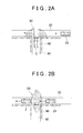
- FIGs. 2A and 2B show a scene at an intersection (a junction) 50 at which a priority road (a second road) 30 and a non-priority road (a first road) 40 are joined to each other.
- the host vehicle 2 will make a direction change by turning left to enter the priority road 30 from the non-priority road 40.
- another vehicle 20 is traveling on the priority road 30 toward the intersection 50.
- the other vehicle 20 is not a following vehicle that follows the host vehicle 2 before the host vehicle 2 makes the direction change by turning left. As shown in FIG.
- the other vehicle 20 will become the following vehicle of the host vehicle 2 and approach host vehicle 2 from behind after the host vehicle 2 completes the direction change by turning left.
- the driving support device 1 recognizes a state of the other vehicle 20, as the following vehicle after the direction change, and provides the rear-side support for the host vehicle 2.
- the host vehicle 2 includes a turn signal operation detection unit 3, a steering angle sensor 4, a front radar 5, a rear radar 6, and an electronic control unit (ECU) 7.
- a turn signal operation detection unit 3 a steering angle sensor 4
- a front radar 5 a rear radar 6
- the turn signal operation detection unit 3 is provided for a turn signal lever of the host vehicle 2 and detects a driver's operation performed on the turn signal lever as turn signal operation information, for example.
- the turn signal operation information includes information indicating whether the driver's operation performed on the turn signal lever is an operation for turning on a right turn signal or an operation for turning on a left turn signal, and information indicating a driver's operation for turning off the turn signal, for example.
- the turn signal operation detection unit 3 outputs the detected turn signal operation information to the ECU 7.
- the steering angle sensor 4 is provided for a steering shaft of the host vehicle 2 and detects a steering angle when the driver operates a steering wheel as steering angle information, for example.
- the steering angle sensor 4 outputs the detected steering angle information to the ECU 7.
- the steering angle information is information about steering of the host vehicle 2, and includes information indicating the steering angle.
- the front radar (a front detection unit) 5 is a sensor that detects an object in front of the host vehicle 2.
- the "front” side here is a side where a front end of a vehicle body is positioned when viewed from a driver's seat.
- the "front” side is a side where the front end of the vehicle body is positioned with respect to a vertical plane that passes through the center of the vehicle body and extends in a vehicle width direction of the host vehicle 2.
- a detection angle of the front radar 5 can be varied up to ⁇ 90 degrees with a vehicle body length direction set as a reference direction (0 degree, taking the right side of the vehicle body length direction as a positive angle side).
- the front radar 5 is a millimeter-wave radar, for example.
- a plurality of millimeter-wave radars may be combined as the front radar 5.
- the millimeter-wave radar is employed as the front radar 5
- the millimeter-wave radar is provided on the front end of the host vehicle 2.
- the millimeter-wave radar detects an object in front of the host vehicle 2 using millimeter radio waves.
- the millimeter-wave radar detects an object such as another vehicle by transmitting millimeter radio waves in front of the host vehicle 2 and receiving millimeter radio waves reflected by the object.
- the millimeter-wave radar may instead be provided on a side surface of the host vehicle 2 near the front end, which allows to detect an object in an obliquely front side area of the host vehicle 2.
- FIG. 2A shows an example of a detection range of front radar 5 of the host vehicle 2.
- each radar has the detection range of the detection angle from approximately -90 degrees to approximately +90 degrees with the vehicle body length direction set as the reference direction (0 degree, taking the right side of the vehicle body length direction as the positive angle side).
- the front radar 5 can detect the other vehicle 20.
- a wall 60 is provided on a side of the non-priority road 40 near the intersection 50 as shown in FIG. 2A , the front radar 5 can detect the other vehicle 20 when the front end of the host vehicle 2 is positioned close to the priority road 30.
- a Laser Imaging Detection and Ranging (LIDAR) or the like may be used as the front radar 5 instead of the millimeter-wave radar.
- the front radar 5 outputs a detection result to the ECU 7.
- the rear radar (a rear detection unit) 6 is a sensor that detects an object in the rear of the host vehicle 2 at a predetermined interval.
- the "rear" side here is a side where a rear end of the vehicle body is positioned when viewed from the driver's seat.
- the "rear” side is a side where the rear end of the vehicle body is positioned with respect to the vertical plane that passes through the center of the vehicle body and extends in the vehicle width direction of the host vehicle 2.
- a detection angle of the rear radar 6 can be varied up to plus-minus 90 degrees with the vehicle body length direction set as a reference direction (0 degree, taking the right side of the vehicle body length direction as a positive angle side).
- the rear radar 6 is a millimeter-wave radar, for example.
- a plurality of millimeter-wave radars may be combined as the rear radar 6.
- the millimeter-wave radar is employed as the rear radar 6, the millimeter-wave radar is provided on the rear end of the host vehicle 2.
- FIG. 2B shows an example of a detection range of rear radar 6 of the host vehicle 2.
- two millimeter-wave radars are provided on the rear end of the host vehicle 2, and each radar has the detection range of the detection angle from approximately - 60 degrees to approximately + 60 degrees with the vehicle body length direction set as the reference direction (0 degree, taking the right side of the vehicle body length direction as the positive angle side).
- the rear radar 6 can detect the other vehicle 20.
- the predetermined interval is set to 50 milliseconds or 100 milliseconds, for example.
- a LIDAR or the like may be used as the rear radar 6 instead of the millimeter-wave radar.
- the rear radar 6 output a detection result to the ECU 7.
- the ECU 7 includes a central processing unit (CPU), a read only memory (ROM), a random access memory (RAM), and the like. In the ECU 7, a program stored in the ROM is loaded into the RAM and then executed by the CPU. The ECU 7 thus performs a acceleration-deceleration control and others.
- the ECU 7 may be constructed of a plurality of electronic control units (ECUs).
- the ECU 7 includes a direction change determination unit 10, an other vehicle recognition unit (recognition unit) 11, a support determination unit 12, and a support unit 13.
- the direction change determination unit 10 determines whether the host vehicle 2 is making a direction change (the host vehicle 2 is changing direction) by turning right or left.
- the direction change determination unit 10 determines whether the host vehicle 2 is making the changing direction by turning right or left, based on the turn signal operation information output from the turn signal operation detection unit 3 and the steering angle information output from the steering angle sensor 4.
- the direction change determination unit 10 determines that the host vehicle 2 is making the direction change when, for example, a condition that the turn signal lever is operated to turn on the turn signal and a condition that a steering angle is equal to or larger than a threshold are both satisfied.
- the direction change determination unit 10 may determine that the host vehicle 2 is changing direction when a condition that the turn signal lever is operated to turn on the turn signal and a condition that a steering angle falls within a predetermined angle range are both satisfied.
- the direction change determination unit 10 may additionally use a current position information received from a GPS receiver (not shown in the drawings) and road information obtained from a map database (not shown in the drawings) to determine whether the host vehicle 2 is making the direction change by turning right or left. In this case, the direction change determination unit 10 may use at least one of the turn signal operation information output from the turn signal operation detection unit 3 and the steering angle information output from the steering angle sensor 4.
- the direction change determination unit 10 may determine whether the host vehicle 2 is making the direction change based on the turn signal operation information output from the turn signal operation detection unit 3, the current position information received from the GPS receiver, and the road information obtained from the map database. When a condition that the turn signal lever is operated to turn on the turn signal and a condition that a current position corresponds to an intersection are both satisfied, the direction change determination unit 10 may determine that the host vehicle 2 starts the direction change by turning right or left, that is, the host vehicle 2 is making the direction change.
- the other vehicle recognition unit 11 recognizes a state of another vehicle 20 in a specific scene, based on the detection result of the front radar 5 obtained before or during the direction change.
- the direction change determination unit 10 determines that the host vehicle 2 is making the direction change by turning right or left
- the other vehicle recognition unit 11 recognizes a state of the other vehicle 20 based on the detection result of the front radar 5 obtained before or during the direction change.
- the other vehicle recognition unit 11 uses, as the detection result of the front radar 5 obtained before the direction change, the detection result of the front radar 5 obtained a predetermined time before the determination that the host vehicle 2 is making the direction change (or starts the direction change) is made to recognize the state of the other vehicle 20.
- the other vehicle recognition unit 11 uses, as the detection result of the front radar 5 obtained during the direction change, the detection result of the front radar 5 obtained while the determination that the host vehicle 2 is making the direction change is being made to recognize the state of the other vehicle 20.
- the other vehicle recognition unit 11 may recognize the state of the other vehicle 20 based on both the detection result obtained before the direction change and the detection result during the direction change.
- the other vehicle 20 travels on the priority road 30 toward the intersection 50, and will follow the host vehicle 2 as the following vehicle after the host vehicle 2 completes the direction change (see FIGs. 2A and 2B ).
- the state of the other vehicle 20 refers to a travel state of the other vehicle 20 or an estimated travel state of the other vehicle 20.
- the state of the other vehicle 20 includes a speed, an acceleration, a deceleration, a travel position, and an estimated amount of time (TTC) before contact between the host vehicle 2 and the other vehicle 20.
- Each of the speed, the acceleration, the deceleration, and the travel position may be an estimated value.
- the TTC is obtained by dividing a distance (a relative position) between the host vehicle 2 and the other vehicle 20 in an advancement direction of the host vehicle 2 by a relative speed between the host vehicle 2 and the other vehicle 20 in the advancement direction.
- the TTC is calculated before the direction change by tuning right or left, so the advancement direction of the host vehicle 2 is different from that of the other vehicle 20.
- the TTC is calculated based on an assumption that the advancement direction of the host vehicle 2 coincides with that of the other vehicle 20.
- the other vehicle recognition unit 11 may recognize the state of the other vehicle 20 based on both the detection result of the front radar 5 obtained before or during the direction change and the detection result of the rear radar 6 obtained after the direction change. Specifically, the other vehicle recognition unit 11 may use the detection result of the front radar 5 in a situation shown in FIG. 2A , and use the detection result of the rear radar 6 in a situation shown in FIG. 2B . With this configuration, the other vehicle recognition unit 11 can obtain more information about an object as compared with a case where the other vehicle recognition unit 11 uses only the detection result of the front radar 5. Thus, accuracy in recognizing the other vehicle 20 is increased.
- the support determination unit 12 determines whether the host vehicle 2 needs the rear-side support in relation to the state of the other vehicle 20, based on the recognition result of the other vehicle recognition unit 11. The support determination unit 12 determines that the host vehicle 2 needs the rear-side support when, for example, a condition that the TTC is smaller than an activation threshold (a predetermined threshold) is satisfied. On the other hand, the support determination unit 12 determines that the host vehicle 2 does not need the rear-side support when the condition that the TTC is smaller than the activation threshold is not satisfied.
- the predetermined threshold is set in advance to determine whether the host vehicle 2 needs the rear-side support. The predetermined threshold is set to 2 seconds, for example.
- the support determination unit 12 outputs a determination result to the support unit 13.
- the support unit 13 provides the rear-side support based on the determination result. For example, the support unit 13 performs at least one the control to turn on the hazard lamp (to blink the light), the control to adjust the position of the headrest to the rear-side support corresponding position, the activation preparation control for the airbag, and the seat belt pretensioner control.
- the driving support device 1 is constructed of the front radar 5, the other vehicle recognition unit 11, and the support determination unit 12. Alternatively, the driving support device 1 may further include the support unit 13.
- FIG. 3 is a flowchart of the rear-side support need determination process.
- the control process shown in FIG. 3 is performed repeatedly at a predetermined interval after a rear-side support system monitor start time has arrived.
- the control process shown in FIG. 3 may be performed in the scene in which the host vehicle 2 reaches the intersection 50 and makes the direction change by turning right or left to enter the priority road 30 from the non-priority road 40, as shown in FIG. 2A .
- the direction change determination unit 10 first determines whether the host vehicle 2 is making the direction change (step S10). For example, the direction change determination unit 10 determines that the host vehicle is making the direction change by turning left when a condition that the turn signal operation information output from the turn signal operation detection unit 3 indicates a left turn and a condition that the steering angle information output from the steering angle sensor 4 indicates a steering angle larger than a threshold are both satisfied.
- the control process proceeds to an other vehicle presence determination process (step S12).
- step S12 the other vehicle recognition unit 11 determines whether the other vehicle 20 traveling on the priority road 30 is present. When it is determined that the other vehicle 20 is present, the control process proceeds to a TTC calculation process (step S14).
- FIGs. 4A and 4B are illustrations that show a process of calculating the TTC.
- FIG. 4A shows a scene in which the rear-side support is provided
- FIG. 4B schematically shows travel paths of the host vehicle 2 and the other vehicle 20 in the scene shown in FIG. 4A .
- FIG. 4B the travel paths of the host vehicle 2 and the other vehicle 20 until 1 second has elapsed from when the host vehicle 2 starts the direction change at a point P1 (0 second).
- the TTC is calculated based on an assumption that the direction change has been completed in 1 second, with reference to a driver's history (a travel history and/or an operation history).
- the TTC may be calculated based on an assumption that the direction change has been completed in X seconds, with reference to the driver's history.
- the other vehicle recognition unit 11 obtains a shape of the intersection 50 from the map database, and predicts the travel path from the current point P1 to an end point P2 on the priority road 30 where the host vehicle 2 reaches in 1 second, using information about the current point P1 obtained from the GPS receiver.
- the end point P2 on the priority road 30 where the host vehicle 2 reaches in 1 second is set based on a speed of the host vehicle 2 at the current point P1 and/or the driver's history.
- the other vehicle recognition unit 11 calculates a length of the travel path.
- the other vehicle recognition unit 11 assumes that the host vehicle 2 is positioned at a point P3 on the priority road 30 away from the end point P2 by a distance corresponding to the calculated length of the travel path.
- the host vehicle 2 and the other vehicle 20 are assumed to be positioned on the same line.
- the other vehicle recognition unit 11 calculates the estimated amount of time to the contact between the host vehicle 2 and the other vehicle 20, based on the relative speed between the host vehicle 2 and the other vehicle 20.
- the control process proceeds to a TTC determination process (step S16) after the other vehicle recognition unit 11 calculates the TTC.
- the support determination unit 12 determines whether the host vehicle 2 needs the rear-side support.
- the support determination unit 12 determines that the host vehicle 2 needs the rear-side support when, for example, a condition that the TTC is smaller than the activation threshold is satisfied.
- the control process proceeds to a rear-side support process (step S18).
- the support unit 13 provides the rear-side support. The control process shown in FIG. 3 is terminated when the rear-side support is completed.
- the direction change determination unit 10 determines that the host vehicle 2 is not making the direction change in step S10 when a condition that the turn signal operation information output from the turn signal operation detection unit 3 indicate a right or left turn, or a condition that the steering angle information output from the steering angle sensor 4 indicates a steering angle larger than the threshold is not satisfied.
- the control process shown in FIG. 3 is terminated.
- the control process shown in FIG. 3 is also terminated.
- step S16 when the condition that the TTC is smaller than the activation threshold is not satisfied in the TTC determination process in step S16, which means that the host vehicle 2 does not need the rear-side support, the control process shown in FIG. 3 is terminated. That is, in any case described above, the rear-side support is not provided in relation to the other vehicle 20 traveling on the priority road 30.
- FIGs. 5A and 5B are illustrations that show a conventional rear-side support need determination.
- An example shown in FIGs. 5A and 5B uses only the rear radar 6 to determine whether the host vehicle 2 needs the rear-side support.
- FIG. 5A shows the host vehicle 2 during a left turn
- FIG. 5B shows the host vehicle 2 immediately after the left turn.
- FIG. 5A shows the host vehicle 2 during a left turn
- FIG. 5B shows the host vehicle 2 immediately after the left turn.
- a rear-side support activation range S1 smaller than the detection range of the rear radar 6 shown in FIG. 2B is set.
- the rear-side support for the host vehicle 2 is provided when an object detected by the rear radar 6 enters the rear-side support activation range S1.
- the other vehicle 20 is not determined as an object that triggers the rear-side support. Note that, in consideration of reduction in erroneous activation, it is difficult to expand the rear-side support activation range S1 to a range wider than a lane width.
- the other vehicle 20 becomes the following vehicle of the host vehicle 2 and enters the rear-side support activation range S1.
- the other vehicle 20 approaching the host vehicle 2 is positioned inside the border of the rear-side support activation range S1.
- the rear-side support is started when the other vehicle 20 reaches the border of the rear-side support activation range S1.
- the rear-side support is started when the other vehicle 20 is positioned closer to the host vehicle, inside the border of the rear-side support activation range S1. As a result, a timing at which the rear-side support is provided is delayed.
- the other vehicle recognition unit 11 in the driving support device 1 recognizes the state of the other vehicle 20, which becomes the following vehicle of the host vehicle 2 after the host vehicle 2 completes the direction change, based on the detection result of the front radar 5 obtained before or during the direction change.
- the state of the other vehicle 20 can be recognized earlier as compared to a case where the state of the other vehicle 20 is recognized by a detection unit with a detection range set in the rear of the host vehicle 2.
- the support determination unit 12 determines whether the host vehicle 2 needs the rear-side support in relation to the state of the other vehicle 20, based on the recognition result of the other vehicle recognition unit 11.
- the state of the other vehicle 20 recognized earlier is used to determine whether the host vehicle 2 needs the rear-side support. This makes it possible to determine whether the host vehicle 2 needs the rear-side support earlier. As a result, the rear-side support can be provided earlier.
- a driving support device has substantially the same configuration as that of the driving support device 1 according to the first embodiment.
- the second embodiment differs from the first embodiment only in that an estimated deceleration of another vehicle 20 is used to determine whether a host vehicle needs a rear-side support, instead of a TTC.
- differences from the first embodiment will be mainly described while duplicate explanations will be omitted.
- FIG. 6 is a flowchart of a rear-side support need determination process performed by the driving support device according to the second embodiment.
- the control process shown in FIG. 6 is performed repeatedly at a predetermined interval after a rear-side support system monitor start time has arrived.
- the control process shown in FIG. 6 may be performed in the scene in which the host vehicle 2 reaches the intersection 50 and makes the direction change by turning right or left to enter the priority road 30 from the non-priority road 40, as shown in FIG. 2A .
- steps S20 and S22 shown in FIG. 6 are the same as those in steps S10 and S12 shown in FIG.3 .
- the control process proceeds to an estimated deceleration calculation process (step S24).
- the other vehicle recognition unit 11 calculates the estimated deceleration based on the state of the other vehicle 20 and a predicted behavior of the host vehicle 2.
- FIG. 7 is an illustration that shows a process of calculating the estimated deceleration.
- the estimated deceleration may be calculated based on an assumption that the direction change has been completed after X seconds has elapsed from the current time, with reference to the driver's history.
- FIG. 7 is an illustration that shows a process of calculating the estimated deceleration.
- the estimated deceleration may be calculated based on an assumption that the direction change has been completed after X seconds has
- a speed of the other vehicle 20 in 1 second has to be smaller than the speed Ve (Condition 1).
- the speed of the other vehicle 20 has to become smaller than the speed Ve while the other vehicle travels the advancement allowed distance Lc (Condition 2).
- the estimated deceleration of the other vehicle 20 is calculated using the above Conditions 1 and 2.
- step S26 the control process proceeds to an estimated deceleration determination process (step S26).
- the support determination unit 12 determines whether the host vehicle 2 needs the rear-side support.
- the estimation deceleration smaller than an activation threshold means a sudden braking to be performed in the other vehicle 20, so the support determination unit 12 determines that the host vehicle needs the rear-side support when a condition that the estimated deceleration is smaller than the activation threshold is satisfied.
- the control process proceeds to a rear-side support process (step S28).
- the support unit 13 provides the rear-side support.
- the support unit 13 performs the control to turn on the hazard lamp, thereby prompting the other vehicle 20 to perform an early braking.
- the control process shown in FIG. 6 is terminated when the rear-side support is completed.
- step S26 when the condition that the estimated deceleration is smaller than the activation threshold is not satisfied in the estimated deceleration determination process in step S26, which means that the host vehicle 2 does not need the rear-side support, the control process shown in FIG. 6 is terminated.
- a negative determination is made in step S20 or S22, a process similar to the process in step S10 or S12 shown in FIG.3 is performed. That is, in any case described above, the rear-side support is not provided in relation to the other vehicle 20 traveling on the priority road 30.
- the rear-side support can be provided earlier and a possibility of a sudden braking to be performed in the other vehicle 20 can be reduced.
- a driving support device differs from the driving support device 1 according to the first embodiment in that a support determination unit 12A uses information obtained by the rear radar 6 to determine whether the host vehicle 2 needs the rear-side support.
- the other configuration of the driving support device according to the third embodiment is the same as that according to the first embodiment.
- differences from the driving support device 1 according to the first embodiment will be mainly described while duplicate explanations will be omitted.
- FIG. 8 is a schematic diagram that illustrates functions of the driving support device according to the third embodiment.
- the driving support device 1A includes the front radar 5, the rear radar 6, the other vehicle recognition unit 11, and the support determination unit 12A.
- the driving support device 1A may further include the support unit 13.
- the rear radar 6 performs periodic detection operation as described above.
- the other vehicle recognition unit 11 counts a successive detection number as the number of times the other vehicle 20 is detected successively by the rear radar 6, based on information output from the rear radar 6.
- the other vehicle recognition unit 11 then outputs the counted successive detection number to the support determination unit 12A.
- the support determination unit 12A determines that the host vehicle 2 needs the rear-side support at least when a condition that the successive detection number is larger than a first threshold is satisfied.
- the first threshold is a predetermined threshold for determining whether the detection result of the rear radar 6 is reliable. That is, the detection result of the rear radar 6 is determined to be reliable when a condition for the successive detection number is satisfied.
- the support determination unit 12A determines that the host vehicle 2 needs the rear-side support at least when a condition that the successive detection number is larger than a second threshold is satisfied.
- the second threshold is smaller than the first threshold.
- FIG. 9 is the flowchart of the threshold change process.
- the control process shown in FIG. 9 is performed repeatedly at a predetermined interval after a rear-side support system monitor start time has arrived.
- the control process shown in FIG. 9 may be performed in the scene in which the host vehicle 2 reaches the intersection 50 and makes the direction change by turning right or left to enter the priority road 30 from the non-priority road 40, as shown in FIG. 2A .
- steps S30 and S32 shown in FIG. 9 are the same as those in steps S10 and S12 shown in FIG.3 .
- the control process proceeds to the threshold change process (step S34).
- the support determination unit 12A changes the threshold of the successive detection number from the first threshold to the second threshold, which is smaller than the first threshold. For example, when the first threshold is set to 10 times, the threshold of the successive detection number is changed to the second threshold set to 5 times.
- the control process shown in FIG. 9 is terminated when the process in step S34 is completed.
- step S30 when it is determined that the host vehicle 2 is not making the direction change in step S30 or when it is determined that the other vehicle 20 is not present in step S32, the control process shown in FIG. 9 is terminated without changing the threshold of the successive detection number.
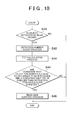
- FIG. 10 is a flowchart of the rear-side support need determination process.
- the control process shown in FIG. 10 starts at a predetermined timing, which is set regardless of scenes, and is performed repeatedly thereafter.
- the other vehicle recognition unit 11 first determines whether the rear radar 6 detects an object (step S40). When it is determined that the rear radar 6 detects an object, the control process proceeds to a count process (step S42).
- step S42 the other vehicle recognition unit 11 counts the successive detection number.
- step S42 the control process proceeds to a TTC calculation process (step S44).
- step S44 the other vehicle recognition unit 11 calculates the TTC based on the detection result of the rear radar 6.
- step S46 the control process proceeds to a rear-side support need determination process (step S46).
- the support determination unit 12A determines that the host vehicle 2 need the rear-side support when a condition that the successive detection number is larger than the threshold and a condition that the TTC is larger than an activation threshold are both satisfied.
- the threshold of the successive detection number here is set in the control process shown in FIG. 9 . Specifically, the first threshold is used when the other vehicle recognition unit 11 does not recognize the other vehicle 20 with the front radar 5, and the second threshold is used when the other vehicle recognition unit 11 recognizes the other vehicle 20 with the front radar 5.
- a rear-side support process is performed (step S48). The process in step S48 is the same as that in step S 18.
- the threshold of the successive detection number which serves as the threshold for performing the rear-side support, is reduced in the driving support device 1 A according to the embodiment. This makes it possible to provide the rear-side support earlier as compared before the threshold of the successive detection number is changed.
- the invention is not limited to the driving support devices in the above described embodiments.
- a sensor other than the front radar 5 may be used to detect an object.
- An image sensor such as a camera may be used to detect an object instead of the front radar 5.
- the rear-side support for the host vehicle 2 is provided at the intersection 50 between the priority road 30 and the non-priority road 40, the rear-side support may be provided at a location other than the intersection 50.
- the rear-side support may be provided at a tree-way junction (a T junction) or a merging point. That is, the invention may be applied to any rear-side support provided at a junction where the two roads are joined to each other.
Landscapes
- Engineering & Computer Science (AREA)
- Mechanical Engineering (AREA)
- Physics & Mathematics (AREA)
- General Physics & Mathematics (AREA)
- Automation & Control Theory (AREA)
- Transportation (AREA)
- Traffic Control Systems (AREA)
- Control Of Driving Devices And Active Controlling Of Vehicle (AREA)
Abstract
Description
- The invention relates to a driving support device and a driving support method.
- A driving support device is described In Japanese Patent Application
2010 -18230 JP 2010-18230 - If the host vehicle traveling on a first road makes a direction change by turning right or left at a junction between the first road and a second road to enter the second road from the first road, the host vehicle will be followed by another vehicle traveling on the second road as a following vehicle. When the host vehicle enters the second road by turning right or left, a difference between a speed of the host vehicle immediately after the direction change and a speed of the other vehicle traveling on the second road toward the junction may be large and the other vehicle may get close to the host vehicle after the host vehicle completes the direction change. In this case, the driving support device described in
JP 2010-18230 A - The invention provides a driving support device and a driving support method that makes it possible to provide the rear-side support for the host vehicle in relation to another vehicle traveling on the second road earlier when the host vehicle makes the direction change by turning right or left and enters the second road from the first road.
- A first aspect of the invention relates to a driving support device for a host vehicle that travels on a first road and makes a direction change, at a junction between the first road and a second road, by turning right or left to enter the second road from the first road. The driving support device includes: a front detection unit configured to detect an object in front of the host vehicle; a recognition unit configured to recognize a state of another vehicle that travels on the second road toward the junction and that follows the host vehicle as a following vehicle after the host vehicle completes the direction change, based on a detection result of the front detection unit obtained before or during the direction change; and a support determination unit configured to determine whether the host vehicle needs a rear-side support in relation to the state of the other vehicle, based on a recognition result of the recognition unit. The driving support device may further include a support unit configured to provide the rear-side support when the support determination unit determines that the host vehicle needs the rear-side support.
- The recognition unit in the above driving support device recognizes the state of the other vehicle, which becomes the following vehicle of the host vehicle after the host vehicle completes the direction change, based on the detection result of the front detection unit obtained before or during the direction change. Thus, the state of the other vehicle can be recognized earlier as compared to a case where the state of the other vehicle is recognized by a detection unit with a detection range set in the rear of the host vehicle. Then, the support determination unit determines whether the host vehicle needs the rear-side support in relation to the state of the other vehicle, based on the recognition result of the other vehicle recognition unit. Thus, the state of the other vehicle recognized earlier is used to determine whether the host vehicle needs the rear-side support. This makes it possible to determine whether the host vehicle needs the rear-side support earlier. As a result, the rear-side support can be provided earlier
- The driving support device may further include a rear detection unit configured to detect an object in a rear of the host vehicle. In this case, the recognition unit may be configured to recognize the state of the other vehicle, based on the detection result of the front detection unit obtained before or during the direction change and a detection result of the rear detection unit obtained after the direction change. With the above configuration, the recognition unit can obtain more information about an object as compared with a case where the recognition unit uses only the detection result of the front detection unit. Thus, accuracy in recognizing the other vehicle is increased.
- The rear detection unit may be configured to periodically detect the object in the rear of the host vehicle at a predetermined interval, and the recognition unit may be configured to count a successive detection number as the number of times the rear detection unit detects the other vehicle successively. In this case, the support determination unit may be configured to determine that the host vehicle needs the rear-side support at least when a condition that the successive detection number is larger than a first threshold is satisfied in a case where the recognition unit does not recognizes that the other vehicle is present based on the detection result of the front detection unit, and to determine that the host vehicle needs the rear-side support at least when a condition that the successive detection number is larger than a second threshold is satisfied in a case where the recognition unit recognizes that the other vehicle is present based on the detection result of the front detection unit. The second threshold may be smaller than the first threshold.
- When the recognition unit has recognized the other vehicle before based on the detection result of the front detection unit, it can be assumed that the other vehicle is detected with a certain degree of reliability. Thus, in this case, the threshold of the successive detection number, which serves as the threshold for performing the rear-side support, is reduced in the above configuration. This makes it possible to provide the rear-side support earlier as compared before the threshold of the successive detection number is changed.
- The rear-side support may be a support that operates one of the host vehicle and an in-vehicle device mounted in the host vehicle before contact between the host vehicle and the other vehicle so as to avoid the contact or reduce an impact of the contact. Further, the rear-side support for the host vehicle may include at least one of a control to turn on a hazard lamp, a control to adjust a position of a headrest to a rear-side support corresponding position, an activation preparation control for an airbag, and a seat belt pretensioner control. When the hazard lamp is turned on in the rear-side support, a driver of a following vehicle is notified of a presence of the host vehicle. This can lead the driver of the following vehicle to avoid the contact. The impact at the time of the contact between the host vehicle and the following vehicle can be reduced by performing at least one of the position adjustment control of the headrest to the rear-side support corresponding position, the activation preparation control for the airbag, and the seat belt pretensioner control in the rear-side support.
- The state of the other vehicle may include an estimated amount of time before contact between the host vehicle and the other vehicle. In this case, the support determination unit may be configured to determine that the host vehicle needs the rear-side support at least when a condition that the estimated amount of time before the contact is smaller than a predetermined threshold is satisfied. With the above configuration, the estimated amount of time before the contact with the other vehicle is used to determine whether the host vehicle needs the rear-side support, and thus the timing at which the rear-side support is provided can be determined.
- The driving support device may further include a direction change determination unit configured to determine whether the host vehicle is making the direction change. In this case, the direction change determination unit may be configured to determine whether the host vehicle is making the direction change based on information indicating turn signal operation and information indicating a steering angle. With the above configuration, the turn signal operation information and the steering angle information is used to determine whether the host vehicle is making the direction change, and thus the determination as to whether the host vehicle is making the direction change can be made more appropriately, as compared with a case where only the turn signal operation information is used.
- A second aspect of the invention relates to a driving support method for a host vehicle that travels on a first road and makes a direction change, at a junction between the first road and a second road, by turning right or left to enter the second road from the first road. The driving support method includes: detecting an object in front of the host vehicle; recognizing a state of another vehicle that travels on the second road toward the junction and that follows the host vehicle as a following vehicle after the host vehicle completes the direction change, based on a result of detecting the object obtained before or during the direction change; and determining whether the host vehicle needs a rear-side support in relation to the state of the other vehicle, based on a result of recognizing the state of the other vehicle. The driving Support method may further include providing the rear-side support when it is determined that the host vehicle needs the rear-side support.
- The above driving support method makes it possible to provide the rear-side support for the host vehicle in relation to the other vehicle traveling on the second road earlier when the host vehicle makes the direction change by turning right or left and enters the second road from the first road.
- Features, advantages, and technical and industrial significance of exemplary embodiments of the invention will be described below with reference to the accompanying drawings, in which like numerals denote like elements, and wherein:
-
FIG. 1 is a schematic diagram that illustrates functions of a driving support device according to a first embodiment; -
FIGs. 2A and 2B are illustrations that show a scene in which a support is provided by the driving support device shown inFIG. 1 ; -
FIG. 3 is a flowchart of a rear-side support need determination process; -
FIGs. 4A and 4B are illustrations that show a process of calculating a TTC; -
FIGs. 5A and 5B are illustrations that show a conventional rear-side support need determination process; -
FIG. 6 is a flowchart of a rear-side support need determination process performed by a driving support device according to a second embodiment; -
FIG. 7 is an illustration that shows a process of calculating an estimated deceleration; -
FIG. 8 is a schematic diagram that illustrates functions of a driving support device according to a third embodiment; -
FIG. 9 is a flowchart of a threshold change process; and -
FIG. 10 is a flowchart of a rear-side support need determination process. - Embodiments of the invention are described hereinafter with reference to the drawings. In the following description, the same reference sign is assigned to the same or corresponding element, and duplicate explanations will be omitted.
-
FIG. 1 is a schematic diagram of a driving support device according to a first embodiment. The drivingsupport device 1 shown inFIG. 1 is a device that provides a rear-side support for ahost vehicle 2. The rear-side support refers to a support that recognizes an object approaching thehost vehicle 2 from behind, and that operates, before contact between the host vehicle and the object, one of thehost vehicle 2 and an in-vehicle device mounted in thehost vehicle 2 so as to avoid the contact or reduce an impact of the contact. The rear-side support includes, specifically, a control to turn on a hazard lamp (to blink a light), a control to adjust a position of a headrest to a rear-side support corresponding position, an activation preparation control for an airbag, and a seat belt pretensioner control. The rear-side support corresponding position of the head rest is a predetermined position at which the headrest is positioned for reducing an impact to be acted on a seated passenger at a time of rear-end contact with another vehicle. A distance between the seated passenger and the head rest is reduced by adjusting the position of the headrest to the rear-side support corresponding position. The activation preparation control for an airbag is, for example, a seat adjustment control for positioning the seated passenger in an appropriate position so that the seated passenger receives a benefit of the airbag. When the hazard lamp is turned on in the rear-side support, a driver of a following vehicle is notified of a presence of the host vehicle. This can lead the driver of the following vehicle to avoid the contact. The impact at the time of the contact between the host vehicle and the following vehicle can be reduced by the position adjustment control of the headrest to the rear-side support corresponding position, the activation preparation control for the airbag, or the seat belt pretensioner control, which is provided as the rear-side support. - First, a scene in which the driving
support device 1 works will be outlined usingFIGs. 2A and 2B. FIGs. 2A and 2B show a scene at an intersection (a junction) 50 at which a priority road (a second road) 30 and a non-priority road (a first road) 40 are joined to each other. Here, thehost vehicle 2 will make a direction change by turning left to enter thepriority road 30 from thenon-priority road 40. At this time, anothervehicle 20 is traveling on thepriority road 30 toward theintersection 50. Theother vehicle 20 is not a following vehicle that follows thehost vehicle 2 before thehost vehicle 2 makes the direction change by turning left. As shown inFIG. 2B , on the other hand, theother vehicle 20 will become the following vehicle of thehost vehicle 2 and approachhost vehicle 2 from behind after thehost vehicle 2 completes the direction change by turning left. In this way, the drivingsupport device 1 recognizes a state of theother vehicle 20, as the following vehicle after the direction change, and provides the rear-side support for thehost vehicle 2. - Back to
FIG. 1 , thehost vehicle 2 includes a turn signaloperation detection unit 3, asteering angle sensor 4, afront radar 5, arear radar 6, and an electronic control unit (ECU) 7. - The turn signal
operation detection unit 3 is provided for a turn signal lever of thehost vehicle 2 and detects a driver's operation performed on the turn signal lever as turn signal operation information, for example. The turn signal operation information includes information indicating whether the driver's operation performed on the turn signal lever is an operation for turning on a right turn signal or an operation for turning on a left turn signal, and information indicating a driver's operation for turning off the turn signal, for example. The turn signaloperation detection unit 3 outputs the detected turn signal operation information to theECU 7. - The
steering angle sensor 4 is provided for a steering shaft of thehost vehicle 2 and detects a steering angle when the driver operates a steering wheel as steering angle information, for example. Thesteering angle sensor 4 outputs the detected steering angle information to theECU 7. The steering angle information is information about steering of thehost vehicle 2, and includes information indicating the steering angle. - The front radar (a front detection unit) 5 is a sensor that detects an object in front of the
host vehicle 2. The "front" side here is a side where a front end of a vehicle body is positioned when viewed from a driver's seat. In other words, the "front" side is a side where the front end of the vehicle body is positioned with respect to a vertical plane that passes through the center of the vehicle body and extends in a vehicle width direction of thehost vehicle 2. A detection angle of thefront radar 5 can be varied up to ±90 degrees with a vehicle body length direction set as a reference direction (0 degree, taking the right side of the vehicle body length direction as a positive angle side). Thefront radar 5 is a millimeter-wave radar, for example. A plurality of millimeter-wave radars may be combined as thefront radar 5. When the millimeter-wave radar is employed as thefront radar 5, the millimeter-wave radar is provided on the front end of thehost vehicle 2. The millimeter-wave radar detects an object in front of thehost vehicle 2 using millimeter radio waves. The millimeter-wave radar detects an object such as another vehicle by transmitting millimeter radio waves in front of thehost vehicle 2 and receiving millimeter radio waves reflected by the object. The millimeter-wave radar may instead be provided on a side surface of thehost vehicle 2 near the front end, which allows to detect an object in an obliquely front side area of thehost vehicle 2.FIG. 2A shows an example of a detection range offront radar 5 of thehost vehicle 2. In this example, two millimeter-wave radars are provided on the both side surfaces of thehost vehicle 2 near the front end, and each radar has the detection range of the detection angle from approximately -90 degrees to approximately +90 degrees with the vehicle body length direction set as the reference direction (0 degree, taking the right side of the vehicle body length direction as the positive angle side). By setting the detection range of thefront radar 5 as described above, thefront radar 5 can detect theother vehicle 20. In addition, if awall 60 is provided on a side of thenon-priority road 40 near theintersection 50 as shown inFIG. 2A , thefront radar 5 can detect theother vehicle 20 when the front end of thehost vehicle 2 is positioned close to thepriority road 30. A Laser Imaging Detection and Ranging (LIDAR) or the like may be used as thefront radar 5 instead of the millimeter-wave radar. Thefront radar 5 outputs a detection result to theECU 7. - The rear radar (a rear detection unit) 6 is a sensor that detects an object in the rear of the
host vehicle 2 at a predetermined interval. The "rear" side here is a side where a rear end of the vehicle body is positioned when viewed from the driver's seat. In other words, the "rear" side is a side where the rear end of the vehicle body is positioned with respect to the vertical plane that passes through the center of the vehicle body and extends in the vehicle width direction of thehost vehicle 2. A detection angle of therear radar 6 can be varied up to plus-minus 90 degrees with the vehicle body length direction set as a reference direction (0 degree, taking the right side of the vehicle body length direction as a positive angle side). Therear radar 6 is a millimeter-wave radar, for example. A plurality of millimeter-wave radars may be combined as therear radar 6. When the millimeter-wave radar is employed as therear radar 6, the millimeter-wave radar is provided on the rear end of thehost vehicle 2.FIG. 2B shows an example of a detection range ofrear radar 6 of thehost vehicle 2. In this example, two millimeter-wave radars are provided on the rear end of thehost vehicle 2, and each radar has the detection range of the detection angle from approximately - 60 degrees to approximately + 60 degrees with the vehicle body length direction set as the reference direction (0 degree, taking the right side of the vehicle body length direction as the positive angle side). In the scene shown inFIG. 2B , therear radar 6 can detect theother vehicle 20. The predetermined interval is set to 50 milliseconds or 100 milliseconds, for example. A LIDAR or the like may be used as therear radar 6 instead of the millimeter-wave radar. Therear radar 6 output a detection result to theECU 7. - The
ECU 7 includes a central processing unit (CPU), a read only memory (ROM), a random access memory (RAM), and the like. In theECU 7, a program stored in the ROM is loaded into the RAM and then executed by the CPU. TheECU 7 thus performs a acceleration-deceleration control and others. TheECU 7 may be constructed of a plurality of electronic control units (ECUs). - The
ECU 7 includes a directionchange determination unit 10, an other vehicle recognition unit (recognition unit) 11, asupport determination unit 12, and asupport unit 13. - The direction
change determination unit 10 determines whether thehost vehicle 2 is making a direction change (thehost vehicle 2 is changing direction) by turning right or left. The directionchange determination unit 10 determines whether thehost vehicle 2 is making the changing direction by turning right or left, based on the turn signal operation information output from the turn signaloperation detection unit 3 and the steering angle information output from thesteering angle sensor 4. The directionchange determination unit 10 determines that thehost vehicle 2 is making the direction change when, for example, a condition that the turn signal lever is operated to turn on the turn signal and a condition that a steering angle is equal to or larger than a threshold are both satisfied. The directionchange determination unit 10 may determine that thehost vehicle 2 is changing direction when a condition that the turn signal lever is operated to turn on the turn signal and a condition that a steering angle falls within a predetermined angle range are both satisfied. The directionchange determination unit 10 may additionally use a current position information received from a GPS receiver (not shown in the drawings) and road information obtained from a map database (not shown in the drawings) to determine whether thehost vehicle 2 is making the direction change by turning right or left. In this case, the directionchange determination unit 10 may use at least one of the turn signal operation information output from the turn signaloperation detection unit 3 and the steering angle information output from thesteering angle sensor 4. The directionchange determination unit 10 may determine whether thehost vehicle 2 is making the direction change based on the turn signal operation information output from the turn signaloperation detection unit 3, the current position information received from the GPS receiver, and the road information obtained from the map database. When a condition that the turn signal lever is operated to turn on the turn signal and a condition that a current position corresponds to an intersection are both satisfied, the directionchange determination unit 10 may determine that thehost vehicle 2 starts the direction change by turning right or left, that is, thehost vehicle 2 is making the direction change. - The other
vehicle recognition unit 11 recognizes a state of anothervehicle 20 in a specific scene, based on the detection result of thefront radar 5 obtained before or during the direction change. When the directionchange determination unit 10 determines that thehost vehicle 2 is making the direction change by turning right or left, the othervehicle recognition unit 11 recognizes a state of theother vehicle 20 based on the detection result of thefront radar 5 obtained before or during the direction change. For example, the othervehicle recognition unit 11 uses, as the detection result of thefront radar 5 obtained before the direction change, the detection result of thefront radar 5 obtained a predetermined time before the determination that thehost vehicle 2 is making the direction change (or starts the direction change) is made to recognize the state of theother vehicle 20. In addition, the othervehicle recognition unit 11 uses, as the detection result of thefront radar 5 obtained during the direction change, the detection result of thefront radar 5 obtained while the determination that thehost vehicle 2 is making the direction change is being made to recognize the state of theother vehicle 20. The othervehicle recognition unit 11 may recognize the state of theother vehicle 20 based on both the detection result obtained before the direction change and the detection result during the direction change. Here, theother vehicle 20 travels on thepriority road 30 toward theintersection 50, and will follow thehost vehicle 2 as the following vehicle after thehost vehicle 2 completes the direction change (seeFIGs. 2A and 2B ). The state of theother vehicle 20 refers to a travel state of theother vehicle 20 or an estimated travel state of theother vehicle 20. Specifically, the state of theother vehicle 20 includes a speed, an acceleration, a deceleration, a travel position, and an estimated amount of time (TTC) before contact between thehost vehicle 2 and theother vehicle 20. Each of the speed, the acceleration, the deceleration, and the travel position may be an estimated value. The TTC is obtained by dividing a distance (a relative position) between thehost vehicle 2 and theother vehicle 20 in an advancement direction of thehost vehicle 2 by a relative speed between thehost vehicle 2 and theother vehicle 20 in the advancement direction. In the embodiment, however, the TTC is calculated before the direction change by tuning right or left, so the advancement direction of thehost vehicle 2 is different from that of theother vehicle 20. Hence, as described below, the TTC is calculated based on an assumption that the advancement direction of thehost vehicle 2 coincides with that of theother vehicle 20. - The other
vehicle recognition unit 11 may recognize the state of theother vehicle 20 based on both the detection result of thefront radar 5 obtained before or during the direction change and the detection result of therear radar 6 obtained after the direction change. Specifically, the othervehicle recognition unit 11 may use the detection result of thefront radar 5 in a situation shown inFIG. 2A , and use the detection result of therear radar 6 in a situation shown inFIG. 2B . With this configuration, the othervehicle recognition unit 11 can obtain more information about an object as compared with a case where the othervehicle recognition unit 11 uses only the detection result of thefront radar 5. Thus, accuracy in recognizing theother vehicle 20 is increased. - The
support determination unit 12 determines whether thehost vehicle 2 needs the rear-side support in relation to the state of theother vehicle 20, based on the recognition result of the othervehicle recognition unit 11. Thesupport determination unit 12 determines that thehost vehicle 2 needs the rear-side support when, for example, a condition that the TTC is smaller than an activation threshold (a predetermined threshold) is satisfied. On the other hand, thesupport determination unit 12 determines that thehost vehicle 2 does not need the rear-side support when the condition that the TTC is smaller than the activation threshold is not satisfied. The predetermined threshold is set in advance to determine whether thehost vehicle 2 needs the rear-side support. The predetermined threshold is set to 2 seconds, for example. Thesupport determination unit 12 outputs a determination result to thesupport unit 13. - The
support unit 13 provides the rear-side support based on the determination result. For example, thesupport unit 13 performs at least one the control to turn on the hazard lamp (to blink the light), the control to adjust the position of the headrest to the rear-side support corresponding position, the activation preparation control for the airbag, and the seat belt pretensioner control. - The driving
support device 1 is constructed of thefront radar 5, the othervehicle recognition unit 11, and thesupport determination unit 12. Alternatively, the drivingsupport device 1 may further include thesupport unit 13. - Next, a rear-side support need determination process according to the embodiment will be described.
FIG. 3 is a flowchart of the rear-side support need determination process. The control process shown inFIG. 3 is performed repeatedly at a predetermined interval after a rear-side support system monitor start time has arrived. The control process shown inFIG. 3 may be performed in the scene in which thehost vehicle 2 reaches theintersection 50 and makes the direction change by turning right or left to enter thepriority road 30 from thenon-priority road 40, as shown inFIG. 2A . - As shown in
FIG. 3 , the directionchange determination unit 10 first determines whether thehost vehicle 2 is making the direction change (step S10). For example, the directionchange determination unit 10 determines that the host vehicle is making the direction change by turning left when a condition that the turn signal operation information output from the turn signaloperation detection unit 3 indicates a left turn and a condition that the steering angle information output from thesteering angle sensor 4 indicates a steering angle larger than a threshold are both satisfied. When it is determined that thehost vehicle 2 is making the direction change, the control process proceeds to an other vehicle presence determination process (step S12). - As the other vehicle presence determination process in step S12, the other
vehicle recognition unit 11 determines whether theother vehicle 20 traveling on thepriority road 30 is present. When it is determined that theother vehicle 20 is present, the control process proceeds to a TTC calculation process (step S14). - As the TTC calculation process in step S 14, the other
vehicle recognition unit 11 calculates the TTC based on an assumption that thehost vehicle 2 and theother vehicle 20 travel on the same road (the priority road 30).FIGs. 4A and 4B are illustrations that show a process of calculating the TTC.FIG. 4A shows a scene in which the rear-side support is provided, andFIG. 4B schematically shows travel paths of thehost vehicle 2 and theother vehicle 20 in the scene shown inFIG. 4A . InFIG. 4B , the travel paths of thehost vehicle 2 and theother vehicle 20 until 1 second has elapsed from when thehost vehicle 2 starts the direction change at a point P1 (0 second). In the embodiment, the TTC is calculated based on an assumption that the direction change has been completed in 1 second, with reference to a driver's history (a travel history and/or an operation history). However, the TTC may be calculated based on an assumption that the direction change has been completed in X seconds, with reference to the driver's history. - The other
vehicle recognition unit 11 obtains a shape of theintersection 50 from the map database, and predicts the travel path from the current point P1 to an end point P2 on thepriority road 30 where thehost vehicle 2 reaches in 1 second, using information about the current point P1 obtained from the GPS receiver. The end point P2 on thepriority road 30 where thehost vehicle 2 reaches in 1 second is set based on a speed of thehost vehicle 2 at the current point P1 and/or the driver's history. Next, the othervehicle recognition unit 11 calculates a length of the travel path. Here, the othervehicle recognition unit 11 assumes that thehost vehicle 2 is positioned at a point P3 on thepriority road 30 away from the end point P2 by a distance corresponding to the calculated length of the travel path. In this way, thehost vehicle 2 and theother vehicle 20 are assumed to be positioned on the same line. With this assumption, the othervehicle recognition unit 11 calculates the estimated amount of time to the contact between thehost vehicle 2 and theother vehicle 20, based on the relative speed between thehost vehicle 2 and theother vehicle 20. - Back to
FIG. 3 , the control process proceeds to a TTC determination process (step S16) after the othervehicle recognition unit 11 calculates the TTC. As the TTC determination process in step S16, thesupport determination unit 12 determines whether thehost vehicle 2 needs the rear-side support. Thesupport determination unit 12 determines that thehost vehicle 2 needs the rear-side support when, for example, a condition that the TTC is smaller than the activation threshold is satisfied. When it is determined that the host vehicle need the rear-side support, the control process proceeds to a rear-side support process (step S18). In the rear-side support process in step S18, thesupport unit 13 provides the rear-side support. The control process shown inFIG. 3 is terminated when the rear-side support is completed. - On the other hand, the direction
change determination unit 10 determines that thehost vehicle 2 is not making the direction change in step S10 when a condition that the turn signal operation information output from the turn signaloperation detection unit 3 indicate a right or left turn, or a condition that the steering angle information output from thesteering angle sensor 4 indicates a steering angle larger than the threshold is not satisfied. When it is determined that thehost vehicle 2 is not making the direction change, the control process shown inFIG. 3 is terminated. When it is determined that theother vehicle 20 is not present in the other vehicle presence determination process in step S12, the control process shown inFIG. 3 is also terminated. Further, when the condition that the TTC is smaller than the activation threshold is not satisfied in the TTC determination process in step S16, which means that thehost vehicle 2 does not need the rear-side support, the control process shown inFIG. 3 is terminated. That is, in any case described above, the rear-side support is not provided in relation to theother vehicle 20 traveling on thepriority road 30. - As described above, with the control process shown in
FIG. 3 , the determination as to whether thehost vehicle 2 needs the rear-side support in relation to theother vehicle 20 traveling on thepriority road 30 is made based on the detection result of thefront radar 5 before or during the direction change. Hereinafter, operation and advantages according to the drivingsupport device 1 will be described as compared with the conventional rear-side support determination.FIGs. 5A and 5B are illustrations that show a conventional rear-side support need determination. An example shown inFIGs. 5A and 5B uses only therear radar 6 to determine whether thehost vehicle 2 needs the rear-side support.FIG. 5A shows thehost vehicle 2 during a left turn, andFIG. 5B shows thehost vehicle 2 immediately after the left turn. InFIG. 5A , a rear-side support activation range S1 smaller than the detection range of therear radar 6 shown inFIG. 2B is set. The rear-side support for thehost vehicle 2 is provided when an object detected by therear radar 6 enters the rear-side support activation range S1. Thus, in a situation shown inFIG. 5A , theother vehicle 20 is not determined as an object that triggers the rear-side support. Note that, in consideration of reduction in erroneous activation, it is difficult to expand the rear-side support activation range S1 to a range wider than a lane width. - As shown in
FIG. 5B , after thehost vehicle 2 completes the left turn, theother vehicle 20 becomes the following vehicle of thehost vehicle 2 and enters the rear-side support activation range S1. At this time, theother vehicle 20 approaching thehost vehicle 2 is positioned inside the border of the rear-side support activation range S1. In the usual scene where theother vehicle 20 approaches thehost vehicle 2 from behind, the rear-side support is started when theother vehicle 20 reaches the border of the rear-side support activation range S1. However, in the scene shown inFIGs. 5A and 5B , the rear-side support is started when theother vehicle 20 is positioned closer to the host vehicle, inside the border of the rear-side support activation range S1. As a result, a timing at which the rear-side support is provided is delayed. - In this respect, the other
vehicle recognition unit 11 in the drivingsupport device 1 according to the embodiment recognizes the state of theother vehicle 20, which becomes the following vehicle of thehost vehicle 2 after thehost vehicle 2 completes the direction change, based on the detection result of thefront radar 5 obtained before or during the direction change. Thus, the state of theother vehicle 20 can be recognized earlier as compared to a case where the state of theother vehicle 20 is recognized by a detection unit with a detection range set in the rear of thehost vehicle 2. Then, thesupport determination unit 12 determines whether thehost vehicle 2 needs the rear-side support in relation to the state of theother vehicle 20, based on the recognition result of the othervehicle recognition unit 11. Thus, the state of theother vehicle 20 recognized earlier is used to determine whether thehost vehicle 2 needs the rear-side support. This makes it possible to determine whether thehost vehicle 2 needs the rear-side support earlier. As a result, the rear-side support can be provided earlier. - A driving support device according to a second embodiment has substantially the same configuration as that of the driving
support device 1 according to the first embodiment. The second embodiment differs from the first embodiment only in that an estimated deceleration of anothervehicle 20 is used to determine whether a host vehicle needs a rear-side support, instead of a TTC. Hereinafter, differences from the first embodiment will be mainly described while duplicate explanations will be omitted. -
FIG. 6 is a flowchart of a rear-side support need determination process performed by the driving support device according to the second embodiment. The control process shown inFIG. 6 is performed repeatedly at a predetermined interval after a rear-side support system monitor start time has arrived. The control process shown inFIG. 6 may be performed in the scene in which thehost vehicle 2 reaches theintersection 50 and makes the direction change by turning right or left to enter thepriority road 30 from thenon-priority road 40, as shown inFIG. 2A . - Processes in steps S20 and S22 shown in
FIG. 6 are the same as those in steps S10 and S12 shown inFIG.3 . When theother vehicle 20 is detected by thefront radar 5, the control process proceeds to an estimated deceleration calculation process (step S24). - As the estimated deceleration calculation process in step S24, the other
vehicle recognition unit 11 calculates the estimated deceleration based on the state of theother vehicle 20 and a predicted behavior of thehost vehicle 2.FIG. 7 is an illustration that shows a process of calculating the estimated deceleration. In a scene shown inFIG. 7 , the estimated deceleration is calculated based on an assumption that the direction change has been completed after 1 second has elapsed from the current time (T = 0 second), with reference to the driver's history. Alternatively, the estimated deceleration may be calculated based on an assumption that the direction change has been completed after X seconds has elapsed from the current time, with reference to the driver's history. In the scene shown inFIG. 7 , theother vehicle 20 needs to be positioned away from thehost vehicle 2 at least by a safety margin distance. in 1 second (T = 1 second). Accordingly, when a distance L denotes a distance between a point on thepriority road 30 at which thehost vehicle 2 is positioned in 1 second (T = 1 second) and a point on thepriority road 30 at which theother vehicle 20 is currently (T = 0 second) positioned, a distance (an advancement allowed distance Lc) by which theother vehicle 20 is allowed to advance during 1 second is obtained by subtracting the distance Lo from the distance L (L - Lo). Further, the relative speed between thehost vehicle 2 and theother vehicle 20 should be made smaller than 0 while theother vehicle 20 travels the advancement allowed distance Lc. That is, when a speed Ve denotes a speed of thehost vehicle 2 at the point on thepriority road 30 at which thehost vehicle 2 completes the direction change (T=1 second), a speed of theother vehicle 20 in 1 second (T=1 second) has to be smaller than the speed Ve (Condition 1). In addition, the speed of theother vehicle 20 has to become smaller than the speed Ve while the other vehicle travels the advancement allowed distance Lc (Condition 2). The estimated deceleration of theother vehicle 20 is calculated using theabove Conditions - Back to
FIG. 6 , after the othervehicle recognition unit 11 calculates the estimated deceleration, the control process proceeds to an estimated deceleration determination process (step S26). As the estimated deceleration determination process in step S26, thesupport determination unit 12 determines whether thehost vehicle 2 needs the rear-side support. For example, the estimation deceleration smaller than an activation threshold means a sudden braking to be performed in theother vehicle 20, so thesupport determination unit 12 determines that the host vehicle needs the rear-side support when a condition that the estimated deceleration is smaller than the activation threshold is satisfied. When it is determined that thehost vehicle 2 needs the rear-side support, the control process proceeds to a rear-side support process (step S28). In the rear-side support process in step S28, thesupport unit 13 provides the rear-side support. As the rear-side support, for example, thesupport unit 13 performs the control to turn on the hazard lamp, thereby prompting theother vehicle 20 to perform an early braking. The control process shown inFIG. 6 is terminated when the rear-side support is completed. - On the other hand, when the condition that the estimated deceleration is smaller than the activation threshold is not satisfied in the estimated deceleration determination process in step S26, which means that the
host vehicle 2 does not need the rear-side support, the control process shown inFIG. 6 is terminated. In a case where a negative determination is made in step S20 or S22, a process similar to the process in step S10 or S12 shown inFIG.3 is performed. That is, in any case described above, the rear-side support is not provided in relation to theother vehicle 20 traveling on thepriority road 30. - Thus, with driving support device according to the embodiment, the rear-side support can be provided earlier and a possibility of a sudden braking to be performed in the
other vehicle 20 can be reduced. - A driving support device according to a third embodiment differs from the driving
support device 1 according to the first embodiment in that asupport determination unit 12A uses information obtained by therear radar 6 to determine whether thehost vehicle 2 needs the rear-side support. The other configuration of the driving support device according to the third embodiment is the same as that according to the first embodiment. Hereinafter, differences from the drivingsupport device 1 according to the first embodiment will be mainly described while duplicate explanations will be omitted. -
FIG. 8 is a schematic diagram that illustrates functions of the driving support device according to the third embodiment. As shown inFIG. 8 , the drivingsupport device 1A includes thefront radar 5, therear radar 6, the othervehicle recognition unit 11, and thesupport determination unit 12A. Alternatively, the drivingsupport device 1A may further include thesupport unit 13. - The
rear radar 6 performs periodic detection operation as described above. The othervehicle recognition unit 11 counts a successive detection number as the number of times theother vehicle 20 is detected successively by therear radar 6, based on information output from therear radar 6. The othervehicle recognition unit 11 then outputs the counted successive detection number to thesupport determination unit 12A. Thesupport determination unit 12A determines that thehost vehicle 2 needs the rear-side support at least when a condition that the successive detection number is larger than a first threshold is satisfied. The first threshold is a predetermined threshold for determining whether the detection result of therear radar 6 is reliable. That is, the detection result of therear radar 6 is determined to be reliable when a condition for the successive detection number is satisfied. On the other hand, in a case where the othervehicle recognition unit 11 has recognized that theother vehicle 20 is present before, thesupport determination unit 12A determines that thehost vehicle 2 needs the rear-side support at least when a condition that the successive detection number is larger than a second threshold is satisfied. The second threshold is smaller than the first threshold. The other configuration of the driving support device according to the third embodiment is the same as that according to the first embodiment. - Next, operation of the driving
support device 1A according to the embodiment will be described. First, a threshold change process for changing a threshold of the successive detection number from the first threshold to the second threshold will be described.FIG. 9 is the flowchart of the threshold change process. The control process shown inFIG. 9 is performed repeatedly at a predetermined interval after a rear-side support system monitor start time has arrived. The control process shown inFIG. 9 may be performed in the scene in which thehost vehicle 2 reaches theintersection 50 and makes the direction change by turning right or left to enter thepriority road 30 from thenon-priority road 40, as shown inFIG. 2A . - Processes in steps S30 and S32 shown in
FIG. 9 are the same as those in steps S10 and S12 shown inFIG.3 . When theother vehicle 20 is detected by thefront radar 5, the control process proceeds to the threshold change process (step S34). - As the threshold change process in step S34, the
support determination unit 12A changes the threshold of the successive detection number from the first threshold to the second threshold, which is smaller than the first threshold. For example, when the first threshold is set to 10 times, the threshold of the successive detection number is changed to the second threshold set to 5 times. The control process shown inFIG. 9 is terminated when the process in step S34 is completed. - On the other hand, when it is determined that the
host vehicle 2 is not making the direction change in step S30 or when it is determined that theother vehicle 20 is not present in step S32, the control process shown inFIG. 9 is terminated without changing the threshold of the successive detection number. - Next, a rear-side support need determination process performed by the driving
support device 1A will be described.FIG. 10 is a flowchart of the rear-side support need determination process. The control process shown inFIG. 10 starts at a predetermined timing, which is set regardless of scenes, and is performed repeatedly thereafter. - As shown in
FIG. 10 , the othervehicle recognition unit 11 first determines whether therear radar 6 detects an object (step S40). When it is determined that therear radar 6 detects an object, the control process proceeds to a count process (step S42). - As the count process in step S42, the other
vehicle recognition unit 11 counts the successive detection number. When the process in step S42 is completed, the control process proceeds to a TTC calculation process (step S44). As the TTC calculation process in step S44, the othervehicle recognition unit 11 calculates the TTC based on the detection result of therear radar 6. When the process in step S44 is completed, the control process proceeds to a rear-side support need determination process (step S46). - As the rear-side support need determination process in step S46, the
support determination unit 12A determines that thehost vehicle 2 need the rear-side support when a condition that the successive detection number is larger than the threshold and a condition that the TTC is larger than an activation threshold are both satisfied. The threshold of the successive detection number here is set in the control process shown inFIG. 9 . Specifically, the first threshold is used when the othervehicle recognition unit 11 does not recognize theother vehicle 20 with thefront radar 5, and the second threshold is used when the othervehicle recognition unit 11 recognizes theother vehicle 20 with thefront radar 5. When it is determined that thehost vehicle 2 needs the rear-side support in step S46, a rear-side support process is performed (step S48). The process in step S48 is the same as that in step S 18. - On the other hand, when an object is not detected in the process in step S40 or when it is determined that the
host vehicle 2 does not need the rear-side support in the process in step S46, the control process shown inFIG. 10 is terminated. - As described above, when the other
vehicle recognition unit 11 has recognized theother vehicle 20 before based on the detection result of thefront radar 5, it can be assumed that theother vehicle 20 is detected with a certain degree of reliability. Thus, in this case, the threshold of the successive detection number, which serves as the threshold for performing the rear-side support, is reduced in the drivingsupport device 1 A according to the embodiment. This makes it possible to provide the rear-side support earlier as compared before the threshold of the successive detection number is changed. - The invention is not limited to the driving support devices in the above described embodiments.
- For example, although an object is detected by the
front radar 5 in the above described embodiments, a sensor other than thefront radar 5 may be used to detect an object. An image sensor such as a camera may be used to detect an object instead of thefront radar 5. - In addition, although the rear-side support for the
host vehicle 2 is provided at theintersection 50 between thepriority road 30 and thenon-priority road 40, the rear-side support may be provided at a location other than theintersection 50. The rear-side support may be provided at a tree-way junction (a T junction) or a merging point. That is, the invention may be applied to any rear-side support provided at a junction where the two roads are joined to each other.
Claims (10)
- A driving support device for a host vehicle (2) that travels on a first road (40) and makes a direction change, at a junction (50) between the first road (40) and a second road (30), by turning right or left to enter the second road (30) from the first road (40), the driving support device characterized by comprising:a front detection unit (5) configured to detect an object in front of the host vehicle (2);a recognition unit (11) configured to recognize a state of another vehicle (20) that travels on the second road (30) toward the junction (50) and that follows the host vehicle (2) as a following vehicle after the host vehicle (2) completes the direction change, based on a detection result of the front detection unit (5) obtained before or during the direction change; anda support determination unit (12; 12A) configured to determine whether the host vehicle (2) needs a rear-side support in relation to the state of the other vehicle (20), based on a recognition result of the recognition unit (11).
- The driving support device according to claim 1, further comprising a rear detection unit (6) configured to detect an object in a rear of the host vehicle (2), wherein
the recognition unit (11) is configured to recognize the state of the other vehicle (20), based on the detection result of the front detection unit (5) obtained before or during the direction change and a detection result of the rear detection unit (6) obtained after the direction change. - The driving support device according to claim 2, wherein:the rear detection unit (6) is configured to periodically detect the object in the rear of the host vehicle (2) at a predetermined interval;the recognition unit (11) is configured to count a successive detection number as the number of times the rear detection unit (6) detects the other vehicle (20) successively;the support determination unit (12A) is configured to determine that the host vehicle (2) needs the rear-side support at least when a condition that the successive detection number is equal to or larger than a first threshold is satisfied in a case where the recognition unit (11) does not recognizes that the other vehicle (20) is present based on the detection result of the front detection unit (5);the support determination unit (12A) is configured to determine that the host vehicle (2) needs the rear-side support at least when a condition that the successive detection number is equal to or larger than a second threshold is satisfied in a case where the recognition unit (11) recognizes that the other vehicle (20) is present based on the detection result of the front detection unit (5); andthe second threshold is smaller than the first threshold.
- The driving support device according to any one of claims 1 to 3, wherein the rear-side support is a support that operates one of the host vehicle (2) and an in-vehicle device mounted in the host vehicle (2) before contact between the host vehicle (2) and the other vehicle (20) so as to avoid the contact or reduce an impact of the contact.
- The driving support device according to claim 4, wherein the rear-side support for the host vehicle (2) includes at least one of a control to turn on a hazard lamp, a control to adjust a position of a headrest to a rear-side support corresponding position, an activation preparation control for an airbag, and a seat belt pretensioner control.
- The driving support device according to any one of claims 1 to 5, wherein:the state of the other vehicle (20) includes an estimated amount of time before contact between the host vehicle (2) and the other vehicle (20); andthe support determination unit (12; 12A) is configured to determine that the host vehicle (2) needs the rear-side support at least when a condition that the estimated amount of time before the contact is smaller than a predetermined threshold is satisfied.
- The driving support device according to any one of claims 1 to 6, further comprising a direction change determination unit (10) configured to determine whether the host vehicle (2) is making the direction change, wherein
the direction change determination unit (12; 12A) is configured to determine whether the host vehicle (2) is making the direction change based on information indicating turn signal operation and information indicating a steering angle. - The driving support device according to any one of claims 1 to 7, further comprising a support unit (13) configured to provide the rear-side support when the support determination unit (12;12A) determines that the host vehicle (2) needs the rear-side support.
- A driving support method for a host vehicle (2) that travels on a first road (40) and makes a direction change, at a junction (50) between the first road (40) and a second road (30), by turning right or left to enter the second road (30) from the first road (40), the driving support method characterized by comprising:detecting an object in front of the host vehicle (2);recognizing a state of another vehicle (20) that travels on the second road (30) toward the junction (50) and that follows the host vehicle (2) as a following vehicle after the host vehicle (2) completes the direction change, based on a result of detecting the object obtained before or during the direction change; anddetermining whether the host vehicle (2) needs a rear-side support in relation to the state of the other vehicle (20), based on a result of recognizing the state of the other vehicle (20).
- The driving support method according to claim 9, further comprising providing the rear-side support when it is determined that the host vehicle (2) needs the rear-side support.
Applications Claiming Priority (1)
| Application Number | Priority Date | Filing Date | Title |
|---|---|---|---|
| JP2014162415A JP6079724B2 (en) | 2014-08-08 | 2014-08-08 | Driving assistance device |
Publications (2)
| Publication Number | Publication Date |
|---|---|
| EP2983154A2 true EP2983154A2 (en) | 2016-02-10 |
| EP2983154A3 EP2983154A3 (en) | 2016-03-16 |
Family
ID=53879351
Family Applications (1)
| Application Number | Title | Priority Date | Filing Date |
|---|---|---|---|
| EP15180026.5A Withdrawn EP2983154A3 (en) | 2014-08-08 | 2015-08-06 | Driving support device and driving support method |
Country Status (4)
| Country | Link |
|---|---|
| US (1) | US9988045B2 (en) |
| EP (1) | EP2983154A3 (en) |
| JP (1) | JP6079724B2 (en) |
| CN (1) | CN105365735A (en) |
Families Citing this family (9)
| Publication number | Priority date | Publication date | Assignee | Title |
|---|---|---|---|---|
| JP6269606B2 (en) * | 2015-07-21 | 2018-01-31 | トヨタ自動車株式会社 | Vehicle control device |
| KR102663017B1 (en) * | 2016-11-24 | 2024-05-07 | 현대자동차주식회사 | Vehicle and method for controlling thereof |
| JP6911739B2 (en) * | 2017-12-13 | 2021-07-28 | トヨタ自動車株式会社 | Driving support device |
| JP6995671B2 (en) * | 2018-03-14 | 2022-01-14 | 本田技研工業株式会社 | Vehicle control devices, vehicle control methods, and programs |
| CN110356390B (en) * | 2018-04-03 | 2022-10-21 | 奥迪股份公司 | Driving assistance system and method |
| CN110497910B (en) * | 2018-05-16 | 2022-10-28 | 奥迪股份公司 | Driving assistance system and method |
| KR20210035523A (en) * | 2019-09-24 | 2021-04-01 | 현대자동차주식회사 | Method and apparatus for vehicle driving control |
| US12263837B2 (en) * | 2021-12-01 | 2025-04-01 | Nauto, Inc. | Devices and methods for assisting operation of vehicles based on situational assessment fusing expoential risks (safer) |
| EP4358061A1 (en) * | 2022-10-19 | 2024-04-24 | Continental Autonomous Mobility Germany GmbH | Vehicle object detection system and method for detecting a target object in a detection area located behind and lateral of a subject vehicle |
Citations (1)
| Publication number | Priority date | Publication date | Assignee | Title |
|---|---|---|---|---|
| JP2010018230A (en) | 2008-07-14 | 2010-01-28 | Toyota Motor Corp | Occupant crash protection device and method for changing operating condition |
Family Cites Families (8)
| Publication number | Priority date | Publication date | Assignee | Title |
|---|---|---|---|---|
| JP2004302621A (en) | 2003-03-28 | 2004-10-28 | Calsonic Kansei Corp | Vehicle collision preventing device |
| JP2005231450A (en) * | 2004-02-18 | 2005-09-02 | Honda Motor Co Ltd | Obstacle detection device for vehicle |
| JP2011037308A (en) | 2009-08-06 | 2011-02-24 | Aisin Seiki Co Ltd | Vehicular occupant protection system |
| JP2011118482A (en) * | 2009-11-30 | 2011-06-16 | Fujitsu Ten Ltd | In-vehicle device and recognition support system |
| JP4964321B2 (en) * | 2010-04-16 | 2012-06-27 | 三菱電機株式会社 | Crew protection device |
| JP2012088904A (en) | 2010-10-19 | 2012-05-10 | Suzuki Motor Corp | Driving support device |
| FR2988507B1 (en) * | 2012-03-23 | 2014-04-25 | Inst Francais Des Sciences Et Technologies Des Transports De Lamenagement Et Des Reseaux | ASSISTANCE SYSTEM FOR A ROAD VEHICLE |
| JP5905846B2 (en) * | 2013-03-29 | 2016-04-20 | 株式会社日本自動車部品総合研究所 | Crossing determination device and program |
-
2014
- 2014-08-08 JP JP2014162415A patent/JP6079724B2/en active Active
-
2015
- 2015-08-04 US US14/817,701 patent/US9988045B2/en active Active
- 2015-08-06 CN CN201510476808.1A patent/CN105365735A/en active Pending
- 2015-08-06 EP EP15180026.5A patent/EP2983154A3/en not_active Withdrawn
Patent Citations (1)
| Publication number | Priority date | Publication date | Assignee | Title |
|---|---|---|---|---|
| JP2010018230A (en) | 2008-07-14 | 2010-01-28 | Toyota Motor Corp | Occupant crash protection device and method for changing operating condition |
Also Published As
| Publication number | Publication date |
|---|---|
| US20160039410A1 (en) | 2016-02-11 |
| JP2016037203A (en) | 2016-03-22 |
| CN105365735A (en) | 2016-03-02 |
| US9988045B2 (en) | 2018-06-05 |
| EP2983154A3 (en) | 2016-03-16 |
| JP6079724B2 (en) | 2017-02-15 |
Similar Documents
| Publication | Publication Date | Title |
|---|---|---|
| US9988045B2 (en) | Driving support device and driving support method | |
| US11014562B2 (en) | Support device | |
| US10625735B2 (en) | Vehicle control apparatus and vehicle control method | |
| US10854081B2 (en) | Driving assistance device and driving assistance method | |
| US10919449B2 (en) | Driving support device and storage medium | |
| JP4211809B2 (en) | Object detection device | |
| US20190073540A1 (en) | Vehicle control device, vehicle control method, and storage medium | |
| US20190263344A1 (en) | Vehicle control device | |
| JP2021014175A (en) | Vehicle control systems, vehicle control methods, and programs | |
| US20180370529A1 (en) | Driving support device and driving support method | |
| US10578714B2 (en) | Vehicle control apparatus and vehicle control method | |
| US20190009787A1 (en) | Vehicle control apparatus, vehicle control method, and vehicle control program | |
| US12208835B2 (en) | Vehicle control device | |
| EP3453582A1 (en) | Driving support apparatus | |
| WO2019012995A1 (en) | Driving support device | |
| US11420624B2 (en) | Vehicle control apparatus and vehicle control method | |
| CN113544031A (en) | Driving support device | |
| WO2019009032A1 (en) | Vehicle control device | |
| US12459514B2 (en) | Vehicle control device, vehicle control method, and storage medium | |
| US11260884B2 (en) | Vehicle control apparatus, vehicle, operation method of vehicle control apparatus, and non-transitory computer-readable storage medium | |
| US20240239314A1 (en) | Vehicle control apparatus | |
| EP4201770B1 (en) | Driving support method and driving support device | |
| US12475711B2 (en) | Object detection device | |
| US12434673B2 (en) | Driving support apparatus, driving support method, and non-transitory computer-readable storage medium | |
| JP2008129871A (en) | Driving environment estimation device |
Legal Events
| Date | Code | Title | Description |
|---|---|---|---|
| PUAI | Public reference made under article 153(3) epc to a published international application that has entered the european phase |
Free format text: ORIGINAL CODE: 0009012 |
|
| 17P | Request for examination filed |
Effective date: 20150905 |
|
| AK | Designated contracting states |
Kind code of ref document: A2 Designated state(s): AL AT BE BG CH CY CZ DE DK EE ES FI FR GB GR HR HU IE IS IT LI LT LU LV MC MK MT NL NO PL PT RO RS SE SI SK SM TR |
|
| AX | Request for extension of the european patent |
Extension state: BA ME |
|
| PUAL | Search report despatched |
Free format text: ORIGINAL CODE: 0009013 |
|
| AK | Designated contracting states |
Kind code of ref document: A3 Designated state(s): AL AT BE BG CH CY CZ DE DK EE ES FI FR GB GR HR HU IE IS IT LI LT LU LV MC MK MT NL NO PL PT RO RS SE SI SK SM TR |
|
| AX | Request for extension of the european patent |
Extension state: BA ME |
|
| RIC1 | Information provided on ipc code assigned before grant |
Ipc: G08G 1/16 20060101AFI20160205BHEP |
|
| STAA | Information on the status of an ep patent application or granted ep patent |
Free format text: STATUS: REQUEST FOR EXAMINATION WAS MADE |
|
| STAA | Information on the status of an ep patent application or granted ep patent |
Free format text: STATUS: THE APPLICATION IS DEEMED TO BE WITHDRAWN |
|
| 18D | Application deemed to be withdrawn |
Effective date: 20160917 |