EP2983099A1 - Method for determining reduction factor of bearing capacity of axial load cylindrical shell structure - Google Patents
Method for determining reduction factor of bearing capacity of axial load cylindrical shell structure Download PDFInfo
- Publication number
- EP2983099A1 EP2983099A1 EP14779155.2A EP14779155A EP2983099A1 EP 2983099 A1 EP2983099 A1 EP 2983099A1 EP 14779155 A EP14779155 A EP 14779155A EP 2983099 A1 EP2983099 A1 EP 2983099A1
- Authority
- EP
- European Patent Office
- Prior art keywords
- load
- cylindrical shell
- imperfection
- dimple
- perturbation
- Prior art date
- Legal status (The legal status is an assumption and is not a legal conclusion. Google has not performed a legal analysis and makes no representation as to the accuracy of the status listed.)
- Granted
Links
Images




Classifications
-
- G—PHYSICS
- G01—MEASURING; TESTING
- G01M—TESTING STATIC OR DYNAMIC BALANCE OF MACHINES OR STRUCTURES; TESTING OF STRUCTURES OR APPARATUS, NOT OTHERWISE PROVIDED FOR
- G01M99/00—Subject matter not provided for in other groups of this subclass
- G01M99/007—Subject matter not provided for in other groups of this subclass by applying a load, e.g. for resistance or wear testing
-
- B—PERFORMING OPERATIONS; TRANSPORTING
- B64—AIRCRAFT; AVIATION; COSMONAUTICS
- B64C—AEROPLANES; HELICOPTERS
- B64C1/00—Fuselages; Constructional features common to fuselages, wings, stabilising surfaces or the like
- B64C1/06—Frames; Stringers; Longerons ; Fuselage sections
- B64C1/068—Fuselage sections
-
- G—PHYSICS
- G06—COMPUTING OR CALCULATING; COUNTING
- G06F—ELECTRIC DIGITAL DATA PROCESSING
- G06F30/00—Computer-aided design [CAD]
- G06F30/20—Design optimisation, verification or simulation
- G06F30/23—Design optimisation, verification or simulation using finite element methods [FEM] or finite difference methods [FDM]
-
- G—PHYSICS
- G06—COMPUTING OR CALCULATING; COUNTING
- G06F—ELECTRIC DIGITAL DATA PROCESSING
- G06F2111/00—Details relating to CAD techniques
- G06F2111/10—Numerical modelling
-
- G—PHYSICS
- G06—COMPUTING OR CALCULATING; COUNTING
- G06F—ELECTRIC DIGITAL DATA PROCESSING
- G06F2113/00—Details relating to the application field
- G06F2113/28—Fuselage, exterior or interior
-
- Y—GENERAL TAGGING OF NEW TECHNOLOGICAL DEVELOPMENTS; GENERAL TAGGING OF CROSS-SECTIONAL TECHNOLOGIES SPANNING OVER SEVERAL SECTIONS OF THE IPC; TECHNICAL SUBJECTS COVERED BY FORMER USPC CROSS-REFERENCE ART COLLECTIONS [XRACs] AND DIGESTS
- Y02—TECHNOLOGIES OR APPLICATIONS FOR MITIGATION OR ADAPTATION AGAINST CLIMATE CHANGE
- Y02T—CLIMATE CHANGE MITIGATION TECHNOLOGIES RELATED TO TRANSPORTATION
- Y02T90/00—Enabling technologies or technologies with a potential or indirect contribution to GHG emissions mitigation
Definitions
- the invention relates to stability analysis with respect to the thin-walled components carrying main load in aerospace or architectural structures, and more particularly to a method for determining a knockdown factor of load-carrying capacity of a cylindrical shell subjected to axial compression.
- a rocket body bears huge takeoff thrust in the launching phase, and thus the axial compressive load is the most important consideration to design a load -carrying structure of the body.
- a propellent tank reinforced by stiffeners bears huge axial compression even though the propellent tank is a secondary load -carrying structure of the rocket body.
- a new generation of large-diameter launch vehicle named CZ-5 is developed in China, and the diameter of the core structure is 5 m. Take the CZ-5 for example, even a liquid oxygen tank reinforced by stiffeners and having a diameter of 3.35 m in the booster system bears an axial compression load over 4000 kN.
- an axially compressed thin-walled component is very sensitive to initial imperfections, especially to initial geometrical imperfections, causing the ultimate load-carrying capacity of the structures estimated on the basis of a perfect model theory or data to be much smaller than that of the actual condition.
- Engineers always employ a "knockdown factor" (or correction factor) which is much smaller than 1 to correct the estimated load -carrying capacity.
- knockdown factor or correction factor
- the ratio of radius to equivalent skin thickness of the shell is larger, imperfection sensitivity is larger, the knockdown factor is smaller, and an allowable load-carrying capacity employed in structure design is smaller when compared with the load-carrying capacity estimated based on the perfect model.
- initial imperfections such as an imperfection with first order eigen -mode shape, imperfection caused by radial perturbation load, and single dimple imperfection were introduced to the perfect cylindrical shell, and then the knockdown factor of the load-carrying capacity of the structure was yielded after calculating the data.
- a more physical method for determining the knockdown factor in consideration of the realistic worst imperfections has not been provided.
- the method introduces the multiple dimple imperfections, on the basis of optimization technologies such as an enumeration method, genetic algorithm and surrogate-based optimization, and yields the combination of a finite number of perturbation loads that causes the realistic worst imperfection, thereby determining the knockdown factor of the load-carrying capacity of the cylindrical shell.
- the invention is more physical, and convenient to be verified via experiments, and yields an estimation having higher fidelity and reliability.
- a method for determining a knockdown factor of load -carrying capacity of a cylindrical shell subjected to axial compression comprises the following steps:
- the effective distance l e can be used to approximately estimate a proper distance between each imperfection using such a combination, and assuming that the disadvantageous influences between adjacent load positions are covered.
- the definition of the distance / under n dimple imperfections is the same as the definition under three dimple imperfections, i.e., under n dimple imperfections, the distance between the circumcenter and the vertex of n-sided regular polygon is /.
- KDF a knockdown factor
- the influence of the amplitude of a single dimple imperfection on the load-carrying capacity is investigated by numerical analysis, so as to determine a range of the load amplitude; then, imperfection sensitivity analysis is performed under multiple dimple imperfections; then, design of experiment is performed by using load amplitudes and load position distribution as design variables; and finally, based on optimization technologies such as the enumeration method, genetic algorithm and surrogate model, the combination of the perturbation loads that represents the realistic worst imperfection with limited amplitude is searched for, and the knockdown factor of the load-carrying capacity of the cylindrical shell is determined, so as to establish a more realistic, reliable, and physically meaningful method for evaluating the imperfection sensitivity and the load-carrying performance of the cylindrical shell subjected to axial compression. It is expected that the method tends to break the conventional norm based on experimental experiences existing at home and abroad, and becomes a method for determining the knockdown factor of the load-carrying capacity in the design of stiffened shells in heavy-lift launch
- a method for determining a knockdown factor of load -carrying capacity of a cylindrical shell subjected to axial compression comprises the following steps:
- a distance between a circumcenter and a vertex of a triangle as l
- varying the distance l from zero calculating corresponding buckling loads
- drawing a curve representing the relationship between the buckling load and the distance / defining the distance corresponding to the minimum buckling load as an effective distance l e .
- the effective distance l e can be used to approximately estimate a proper distance between each imperfection using such a combination, and assuming that the disadvantageous influences between adjacent load positions are covered.
- the definition of the distance l under n dimple imperfections is the same as the definition under three dimple imperfections, i.e., under n dimple imperfections, the distance between the circumcenter and the vertex of n-sided regular polygon is l .
- the combination shape can be used to approximately estimate a proper distance between each imperfection to know the realistic worst imperfection of the three dimple imperfections.
- a comparatively large radial perturbation load does not necessarily cause the generation of the minimum buckling load, so the radial perturbation load N as a design variable, N max as an upper bound, zero or a small empirical value as a lower bound.
- the optimization objective is to minimize the buckling load of the cylindrical shell with the combined dimple imperfection.
- KDF a knockdown factor
- T-rings are attached to both the bottom end and top end of the cylindrical shell, and made by the same material as the cylindrical shell. The bottom end of the T-rings is entirely clamped and the top end of the T-rings is constrained except for axial translational displacement.
- initial imperfections are introduced to the positions that are evenly distributed along the axial direction, and thereby a curve of the perturbation load vs. the buckling load of the structure can be drawn.
- the corresponding radial perturbation load M max is 30 N.
- the combination of the perturbation loads that represents the realistic worst imperfection is searched below using optimization technologies such as the enumeration method and surrogate model respectively.
- T-rings which are made by 2024 aluminum alloy are attached to both the bottom end and top end of the cylindrical shell.
- the bottom end of the T-rings is entirely clamped and the top end of the T-rings is constrained except for axial translational displacement.
- initial imperfections are introduced to the positions that are evenly distributed along the axial direction, and thereby a curve of the perturbation load vs. the buckling load of the structure can be drawn, as shown in FIG. 12 .
- the initial imperfection 1.5 mm
- the corresponding radial perturbation load M max is calculated.
- imperfections of four load positions ( N 1 , N 2 , N 3 and N 4 ) are introduced, and corresponding value of l when the minimum buckling load occurs is searched for, then the / is defined as l e , therefore n a and n c are yielded after calculation, so the number of possible dimple positions on the shell skin can be calculated.
- the combination of the perturbation loads that represents the realistic worst imperfection is searched below using optimization technologies such as the enumeration method and the surrogate model respectively.
- T-rings are attached to both the bottom end and top end of the cylindrical shell, and made by the same material as the cylindrical shell. The bottom end of the T-rings is entirely clamped and the top end of the T-rings is constrained except for axial translational displacement.
- initial imperfections are introduced to the positions that are evenly distributed along the axial direction, and thereby a curve of the perturbation load vs. the buckling load of the structure can be drawn, as shown in FIG. 18 .
- the initial imperfection 1.5 mm
- the corresponding radial perturbation load N max is calculated.
Landscapes
- Engineering & Computer Science (AREA)
- Physics & Mathematics (AREA)
- Theoretical Computer Science (AREA)
- General Physics & Mathematics (AREA)
- Mechanical Engineering (AREA)
- Aviation & Aerospace Engineering (AREA)
- Computer Hardware Design (AREA)
- Evolutionary Computation (AREA)
- Geometry (AREA)
- General Engineering & Computer Science (AREA)
- Investigating Strength Of Materials By Application Of Mechanical Stress (AREA)
- Management, Administration, Business Operations System, And Electronic Commerce (AREA)
Abstract
Description
- The invention relates to stability analysis with respect to the thin-walled components carrying main load in aerospace or architectural structures, and more particularly to a method for determining a knockdown factor of load-carrying capacity of a cylindrical shell subjected to axial compression.
- A rocket body bears huge takeoff thrust in the launching phase, and thus the axial compressive load is the most important consideration to design a load -carrying structure of the body. A propellent tank reinforced by stiffeners bears huge axial compression even though the propellent tank is a secondary load -carrying structure of the rocket body. A new generation of large-diameter launch vehicle named CZ-5 is developed in China, and the diameter of the core structure is 5 m. Take the CZ-5 for example, even a liquid oxygen tank reinforced by stiffeners and having a diameter of 3.35 m in the booster system bears an axial compression load over 4000 kN. However, an axially compressed thin-walled component is very sensitive to initial imperfections, especially to initial geometrical imperfections, causing the ultimate load-carrying capacity of the structures estimated on the basis of a perfect model theory or data to be much smaller than that of the actual condition. Engineers always employ a "knockdown factor" (or correction factor) which is much smaller than 1 to correct the estimated load -carrying capacity. In general, when the ratio of radius to equivalent skin thickness of the shell is larger, imperfection sensitivity is larger, the knockdown factor is smaller, and an allowable load-carrying capacity employed in structure design is smaller when compared with the load-carrying capacity estimated based on the perfect model. As the launching load of the new generation of launch vehicles and heavy-lift launch vehicles in the future improve by leaps and bounds, the diameters of the rockets also tend to largely increase, and the imperfection sensitivity of load-carrying cylindrical shells becomes increasingly prominent, thus it is crucial to develop a novel method for determining the knockdown factor of load-carrying capacity of the cylindrical shell under axial compression.
- Conventional methods for evaluating imperfection sensitivity of cylindrical shell, represented by NASA SP-8007, mainly employ a semi-empirical formula and yield the knockdown factor of the load-carrying capacity of the cylindrical shell based on a large quantity of experiments. With the development of manufacturing technology and material system, the conventional methods turn out to be extremely conservative, bringing in much costs and design redundancy. In view of the above-mentioned problems, many specialists employ the numerical analysis method to investigate the imperfection sensitivity of cylindrical shells. According to the method, initial imperfections such as an imperfection with first order eigen -mode shape, imperfection caused by radial perturbation load, and single dimple imperfection were introduced to the perfect cylindrical shell, and then the knockdown factor of the load-carrying capacity of the structure was yielded after calculating the data. Though large amount of related work has been carried out, a more physical method for determining the knockdown factor in consideration of the realistic worst imperfections has not been provided.
- In conclusion, it is necessary to put forward an improved method for determining the knockdown factor of the load-carrying capacity of the cylindrical shell, which is convenient to be verified via experiments.
- In view of the above-described problems, it is one objective of the invention to provide a method for determining a knockdown factor of load-carrying capacity of a cylindrical shell subjected to axial compression based on the combination of the perturbation loads that represents the realistic worst imperfection. The method introduces the multiple dimple imperfections, on the basis of optimization technologies such as an enumeration method, genetic algorithm and surrogate-based optimization, and yields the combination of a finite number of perturbation loads that causes the realistic worst imperfection, thereby determining the knockdown factor of the load-carrying capacity of the cylindrical shell. Compared with conventional methods for evaluating imperfection sensitivity based on experimental experiences, represented by NASA SP-8007, the invention is more physical, and convenient to be verified via experiments, and yields an estimation having higher fidelity and reliability.
- To achieve the above objective, in accordance with one embodiment of the invention, there is provided a method for determining a knockdown factor of load -carrying capacity of a cylindrical shell subjected to axial compression. The method comprises the following steps:
- 1) introducing single dimple imperfection to a perfect cylindrical shell by applying radial perturbation load to the perfect cylindrical shell, calculating load -carrying capacities of the cylindrical shell subjected to axial compression with different amplitudes of dimple imperfection through finite element analysis, performing imperfection sensitivity analysis to obtain a relationship between radial perturbation load and its sensitivity to load-carrying capacity of structure, and determining a rational perturbation load range, where the considered maximum imperfection amplitude corresponding to a maximum perturbation load Nmax is determined by fabrication quality and detection tolerance;
- 2) performing imperfection sensitivity analysis using the combined dimple shape after introducing the dimple imperfections following the operations in 1), where a vertex of a regular polygon acts as the load position of the radial perturbation load.
- In an example involving three dimple imperfections, defining a distance between a circumcenter and a vertex of a triangle as /, varying the distance / from zero, calculating corresponding buckling loads, and drawing a curve representing the relationship between the buckling load and the distance /; defining the distance corresponding to the minimum buckling load as an effective distance le . The effective distance le can be used to approximately estimate a proper distance between each imperfection using such a combination, and assuming that the disadvantageous influences between adjacent load positions are covered. Assuming that the load positions are equally distributed on the cylindrical shell, and thus Sa and Sc are the distances of two adjacent load positions in the axial and circumferential directions, respectively, na and nc are the numbers of load positions in the axial and circumferential directions, respectively, calculation formulas thereof being as follows:


- To facilitate calculation, herein defining l as le , and after determining na and nc , assigning a position number to each load position (the position number starting from zero degree at the bottom of the cylindrical shell, successively increasing from the bottom to the top along the axial direction, and successively increasing along the circumferential direction). Based on a large amount of previous analysis experiences, a comparatively large radial perturbation load does not necessarily lead to the minimum buckling load. Setting the amplitude of radial perturbation load N as a design variable, Nmax as the upper bound, zero or a small empirical value as the lower bound. Considering that large number of dimple imperfections increase the sampling points in design of experiment, which expends a high computation cost, and considering that the cylindrical shells in aerospace field with too many imperfections would be defined as substandard products in the industrial applications, it is suggested that an optimization is performed based on three dimple imperfections.
- 3) In the design of experiment, the amplitude of radial perturbation load N and the numbers of the load positions of the dimple imperfections na , nc are selected as variables; and
- 4) determining the combination of the perturbation loads that represents the realistic worst imperfection for the cylindrical shell using optimization technologies such as an enumeration method, genetic algorithm and surrogate-based optimization. The optimization objective is to minimize the buckling load of the cylindrical shell with the combined dimple imperfection. The optimization formulation is expressed as follows:


- After the optimization, a knockdown factor (KDF) is calculated via a formula:
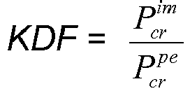


- Compared with existing technologies, advantages of the method according to embodiments of the invention are given below: different from conventional methods for evaluating imperfection sensitivity based on experimental experience, represented by NASA SP-8007, a single dimple imperfection is introduced by applying a radial perturbation load. First, the influence of the amplitude of a single dimple imperfection on the load-carrying capacity is investigated by numerical analysis, so as to determine a range of the load amplitude; then, imperfection sensitivity analysis is performed under multiple dimple imperfections; then, design of experiment is performed by using load amplitudes and load position distribution as design variables; and finally, based on optimization technologies such as the enumeration method, genetic algorithm and surrogate model, the combination of the perturbation loads that represents the realistic worst imperfection with limited amplitude is searched for, and the knockdown factor of the load-carrying capacity of the cylindrical shell is determined, so as to establish a more realistic, reliable, and physically meaningful method for evaluating the imperfection sensitivity and the load-carrying performance of the cylindrical shell subjected to axial compression. It is expected that the method tends to break the conventional norm based on experimental experiences existing at home and abroad, and becomes a method for determining the knockdown factor of the load-carrying capacity in the design of stiffened shells in heavy-lift launch vehicles in China.
-
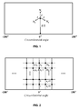
FIG. 1 is a schematic diagram of the distribution of the load positions of three dimple imperfections in accordance with one exemplary embodiment of the invention; -
FIG. 2 is a schematic diagram of position numbers for the load positions in accordance with one exemplary embodiment of the invention; -
FIG. 3 is a curve of imperfection sensitivities of different dimple positions in a cylindrical shell in accordance with one exemplary embodiment of the invention; -
FIG. 4 is a schematic diagram of a metal cylindrical shell subjected to axial compression and T-rings in accordance with one exemplary embodiment of the invention; -
FIG. 5 is a schematic diagram of the distribution of five dimple positions (Z1 to Z5) along the axial direction in accordance with one exemplary embodiment of the invention; -
FIG. 6 is a schematic diagram of the influence of the distance l on the buckling load of a cylindrical shell in accordance with one exemplary embodiment of the invention; -
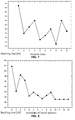
FIG. 7 is a schematic diagram of a searching process of the combination of the perturbation loads that represents the realistic worst imperfection based on an enumeration method in accordance with one exemplary embodiment of the invention; -
FIG. 8 is a diagram of a searching process of the combination of the perturbation loads that represents the realistic worst imperfection based on a surrogate model in accordance with one exemplary embodiment of the invention; -
FIG. 9 is a flow chart of a method for determining a knockdown factor of load-carrying capacity of a cylindrical shell subjected to axial compression in accordance with one exemplary embodiment of the invention; -
FIG. 10 is a schematic diagram of the axially compressed cylindrical shell made by composite materials, and metal T-rings in accordance with one exemplary embodiment of the invention; -
FIG. 11 is a schematic diagram of the distribution of five dimple positions (Z1 to Z5) along the axial direction of an axially compressed cylindrical shell made by composite materials in accordance with one exemplary embodiment of the invention; -
FIG. 12 is a curve of imperfection sensitivities of different dimple positions in an axially compressed cylindrical shell made by composite materials in accordance with one exemplary embodiment of the invention; -
FIG. 13 is a schematic diagram of the distribution of the load positions of four dimple imperfections in an axially compressed cylindrical shell made by composite materials in accordance with one exemplary embodiment of the invention; -
FIG. 14 is a diagram of a searching process of the combination of the perturbation loads that represents the realistic worst imperfection based on an enumeration method in an axially compressed cylindrical shell made by composite materials in accordance with one exemplary embodiment of the invention; -
FIG. 15 is a diagram of a searching process of the combination of the perturbation loads that represents the realistic worst imperfection based on a surrogate model in an axially compressed cylindrical shell made by composite materials in accordance with one exemplary embodiment of the invention; -
FIG. 16 is a schematic diagram of a large-size metal cylindrical shell subjected to axial compression and T-rings in accordance with one exemplary embodiment of the invention; -
FIG. 17 is a schematic diagram of the distribution of six dimple positions (Z1 to Z6) along the axial direction of a large-size metal cylindrical shell subjected to axial compression in accordance with one exemplary embodiment of the invention; -
FIG. 18 is a curve of imperfection sensitivities of different dimple positions in a large-size metal cylindrical shell subjected to axial compression in accordance with one exemplary embodiment of the invention; -
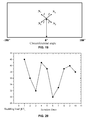
FIG. 19 is a schematic diagram of the load positions of four dimple imperfections in a large-size metal cylindrical shell subjected to axial compression in accordance with one exemplary embodiment of the invention; -
FIG. 20 is a diagram of a searching process of the combination of the perturbation loads that represents the realistic worst imperfection based on an enumeration method in a large-size metal cylindrical shell subjected to axial compression in accordance with one exemplary embodiment of the invention; and -
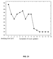
FIG. 21 is a diagram of a searching process of the combination of the perturbation loads that represents the realistic worst imperfection based on a surrogate model in a large-size metal cylindrical shell subjected to axial compression in accordance with one exemplary embodiment of the invention. - For further illustrating the invention, experiments detailing a method for determining a knockdown factor of load-carrying capacity of a cylindrical shell subjected to axial compression are described below. It should be noted that the following examples are intended to describe and not to limit the invention.
- As shown in
FIG. 9 , a method for determining a knockdown factor of load -carrying capacity of a cylindrical shell subjected to axial compression comprises the following steps: - 1) introducing dimple imperfections to a perfect cylindrical shell by applying radial perturbation load to the perfect cylindrical shell, calculating load-carrying capacities of the cylindrical shell subjected to axial compression with different amplitudes of dimple imperfection through finite element analysis, performing imperfection sensitivity analysis to obtain a relationship between radial perturbation load and its sensitivity to load-carrying capacity of structure, and determining a rational perturbation load range, where the considered maximum imperfection amplitude corresponding to a maximum perturbation load Nmax is determined by fabrication quality and detection tolerance;
- 2) performing imperfection sensitivity analysis using the combined dimple shape after introducing the dimple imperfections following the operations in 1), where a vertex of a regular polygon acts as the load position of the radial perturbation load.
- As shown in
FIG. 1 , in an example involving three dimple imperfections, defining a distance between a circumcenter and a vertex of a triangle as l, varying the distance l from zero, calculating corresponding buckling loads, and drawing a curve representing the relationship between the buckling load and the distance /; defining the distance corresponding to the minimum buckling load as an effective distance le . The effective distance le can be used to approximately estimate a proper distance between each imperfection using such a combination, and assuming that the disadvantageous influences between adjacent load positions are covered. Assuming that the load positions are equally distributed on the cylindrical shell, and thus Sa and Sc are the distances of two adjacent load positions in the axial and circumferential directions, respectively, na and nc are the numbers of load positions in the axial and circumferential directions, respectively, calculation formulas thereof being as follows:


- To facilitate calculation, herein defining l as le , the combination shape can be used to approximately estimate a proper distance between each imperfection to know the realistic worst imperfection of the three dimple imperfections. After determining na and nc , as shown in
FIG. 2 , assigning a position number to each load position, the position number starting from zero degree at the bottom of the cylindrical shell, successively increasing from the bottom to the top along the axial direction, and then successively increasing along the circumferential direction; setting the amplitude of radial perturbation load N as a design variable, Nmax as the upper bound, zero or a small empirical value as the lower bound; considering the calculation efficiency, it is suggested that an optimization is performed based on three dimple imperfections. - As shown in
FIG. 3 , a comparatively large radial perturbation load does not necessarily cause the generation of the minimum buckling load, so the radial perturbation load N as a design variable, Nmax as an upper bound, zero or a small empirical value as a lower bound. Considering that large number of dimple imperfections increase the sampling points in design of experiment, which expends a high computation cost, and considering that the cylindrical shells in aerospace field with too many imperfections would be defined as substandard products in the industrial applications, it is suggested that an optimization is performed based on three dimple imperfections. - 3) In the design of experiment, the amplitude of radial perturbation load N and the numbers of the load positions of the dimple imperfections na , nc are defined as variables; and
- 4) determining the combination of the perturbation loads that represents the realistic worst imperfection for the cylindrical shell using optimization technologies selected from an enumeration method, genetic algorithm and surrogate model. As shown in
FIG. 2 , the optimization objective is to minimize the buckling load of the cylindrical shell with the combined dimple imperfection. The optimization formulation is expressed as follows:


- After the optimization, a knockdown factor (KDF) is calculated via a formula:


- As shown in
FIG. 4 , a radius of the metal cylindrical shell R = 250 mm, a length L = 510 mm, a thickness t = 0.5 mm. Material properties of 2024 aluminum alloy are as follows: elastic modulus E = 72 GPa, Poisson's ratio U = 0.31, yield stress σ s = 363 MPa, ultimate stress σ b = 463 MPa, and density ρ = 2.8E-6 kg/mm3. For the convenience of fixing and loading, T-rings are attached to both the bottom end and top end of the cylindrical shell, and made by the same material as the cylindrical shell. The bottom end of the T-rings is entirely clamped and the top end of the T-rings is constrained except for axial translational displacement. - As shown in
FIG. 5 , initial imperfections are introduced to the positions that are evenly distributed along the axial direction, and thereby a curve of the perturbation load vs. the buckling load of the structure can be drawn. When the initial imperfection (1.5 mm) is 3 times as thick as the shell skin, the corresponding radial perturbation load Mmax is 30 N. As shown inFIG. 1 , imperfections at three load positions (N1 , N2 , and N3 ) are introduced, and as shown inFIG. 6 , the minimum buckling load occurs when l = 45 mm and / is defined as le , therefore na = 7 and nc = 40 after calculation, so the number of possible dimple positions on the shell skin are 280. The combination of the perturbation loads that represents the realistic worst imperfection is searched below using optimization technologies such as the enumeration method and surrogate model respectively. - 1) The enumeration method. Ten combinations are generated randomly based on the 280 possible dimple positions, and the load-carrying capacity of the structure is thereby analyzed, as shown in
FIG. 7 , the minimum buckling load occurs at the eighth iteration, thus the eighth is considered as the combination of the perturbation loads that represents the realistic worst imperfection. Of course, more enumerations are beneficial for finding the realistic worst imperfection. - 2) The surrogate model. In the design domain, 100 sample points are generated by performing a design of experiment, and thereby a surrogate model is built. Then a multi-island genetic algorithm is employed for optimization. An optimal solution is achieved at the thirteenth iteration, as shown in
FIG. 8 , and finally the knockdown factor is determined to be 0.42 which is better than the existing knockdown factor 0.32 suggested by the NASA SP-8007. The method effectively reduces design redundancy, and the improved knockdown factor can further decrease the structural weight. - As shown in
FIG. 10 , a radius of a cylindrical shell made by composite materials R = 250 mm, a length L = 510 mm, a ply angle thereof is [45/-45/45/ -45/45] and thickness of each layer t = 0.1 mm. Material properties are as follows: E11 = 84.56 GPa, E22 = 6.86 GPa, G12 = G13 = 4.9 GPa, G23 = 1.96 GPa, U12 = 0.3, ρ = 1.7E-6 kg/mm3. For the convenience of fixing and loading, T-rings which are made by 2024 aluminum alloy are attached to both the bottom end and top end of the cylindrical shell. Material properties of the 2024 aluminum alloy are as follows: elastic modulus E = 72 GPa, Poisson's ratio U = 0.31, yield stress σs = 363 MPa, ultimate stress σ b = 463 MPa, and density ρ = 2.8E-6 kg/mm3. The bottom end of the T-rings is entirely clamped and the top end of the T-rings is constrained except for axial translational displacement. - As shown in
FIG. 11 , initial imperfections are introduced to the positions that are evenly distributed along the axial direction, and thereby a curve of the perturbation load vs. the buckling load of the structure can be drawn, as shown inFIG. 12 . Assuming that the initial imperfection (1.5 mm) is 3 times as thick as the shell skin, the corresponding radial perturbation load Mmax is calculated. As shown inFIG. 13 , imperfections of four load positions (N1 , N2 , N3 and N4 ) are introduced, and corresponding value of l when the minimum buckling load occurs is searched for, then the / is defined as le , therefore na and nc are yielded after calculation, so the number of possible dimple positions on the shell skin can be calculated. The combination of the perturbation loads that represents the realistic worst imperfection is searched below using optimization technologies such as the enumeration method and the surrogate model respectively. - 1) The enumeration method. Ten combinations are generated randomly based on the possible dimple positions, and the load-carrying capacity of the structure is thereby analyzed, as shown in
FIG. 14 , the minimum buckling load occurs at the fifth iteration, thus the fifth is considered as the combination of the perturbation loads that represents the realistic worst imperfection. Of course, more enumerations are beneficial for finding the realistic worst imperfection. - 2) The surrogate model. In the design domain, 100 sample points are generated by performing a design of experiment, and thereby a surrogate model is built. Then a multi-island genetic algorithm is employed for optimization. An optimal solution is achieved at the twelfth iteration, as shown in
FIG. 15 , and finally the knockdown factor is determined. - As shown in
FIG. 16 , a radius of the metal cylindrical shell R = 300 mm, a length L = 600 mm, a thickness t = 0.5 mm. Material properties of the 2024 aluminum alloy are as follows: elastic modulus E = 72 GPa, Poisson's ratio U = 0.31, yield stress σ s = 363 MPa, ultimate stress σ b = 463 MPa, and density ρ = 2.8E-6 kg/mm3. For the convenience of fixing and loading, T-rings are attached to both the bottom end and top end of the cylindrical shell, and made by the same material as the cylindrical shell. The bottom end of the T-rings is entirely clamped and the top end of the T-rings is constrained except for axial translational displacement. - As shown in
FIG. 17 , initial imperfections are introduced to the positions that are evenly distributed along the axial direction, and thereby a curve of the perturbation load vs. the buckling load of the structure can be drawn, as shown inFIG. 18 . Assuming that the initial imperfection (1.5 mm) is 3 times as thick as the shell skin, the corresponding radial perturbation load Nmax is calculated. As shown inFIG. 19 , imperfections of four load positions (N1 , N2 , N3 and N4 ) are introduced, and corresponding value of l when the minimum buckling load occurs is searched for, then the / is defined as le , therefore na and nc are yielded after calculation, so the number of possible dimple positions on the shell skin can be calculated. The combination of the perturbation loads that represents the realistic worst imperfection is searched below using optimization technologies such as the enumeration method and the surrogate model respectively. - 1) The enumeration method. Ten combinations are generated randomly based on the possible dimple positions, and the load-carrying capacity of the structure is thereby analyzed, as shown in
FIG. 20 , the minimum buckling load occurs at the sixth iteration, thus the sixth is considered as the realistic worst imperfection. Of course, more enumerations are beneficial for finding the realistic worst imperfection. - 2) The surrogate model. In the design domain, 100 sample points are generated by performing a design of experiment, and thereby a surrogate model is built. Then a multi-island genetic algorithm is employed for optimization. An optimal solution is achieved at the fourteenth iteration, as shown in
FIG. 21 , and finally the knockdown factor is determined. - While particular embodiments of the invention have been shown and described, it will be obvious to those skilled in the art that changes and modifications may be made without departing from the invention in its broader aspects, and therefore, the aim in the appended claims is to cover all such changes and modifications as fall within the true spirit and scope of the invention.
Claims (1)
- A method for determining a knockdown factor of load-carrying capacity of a cylindrical shell subjected to axial compression, the method comprising:a) introducing single dimple imperfection to a perfect cylindrical shell by applying radial perturbation load to the perfect cylindrical shell, calculating load-carrying capacities of the cylindrical shell subjected to axial compression with different amplitudes of dimple imperfection through finite element analysis, performing imperfection sensitivity analysis to obtain a relationship between radial perturbation load and a sensitivity to load-carrying capacity of structure, and determining a rational perturbation load range, where a considered maximum imperfection amplitude corresponding to a maximum perturbation load Nmax is determined by fabrication quality and detection tolerance;b) performing imperfection sensitivity analysis using a combined dimple shape after introducing the dimple imperfections following the operations in 1), where a vertex of a regular polygon acts as the load position of the radial perturbation load;
for n dimple imperfections, defining a distance between a circumcenter and a vertex of a n-sided regular polygon as l, varying the distance l from zero, calculating corresponding buckling loads, and drawing a curve representing the relationship between the buckling load and the distance l; defining the distance corresponding to a minimum buckling load as an effective distance le , Sa and Sc being distances of two adjacent load positions in the axial and circumferential directions, respectively, na and nc being the numbers of load positions in the axial and circumferential directions, respectively, calculation formulas thereof being as follows:


where, L is an axial height of the cylindrical shell, R is a radius of the cylindrical shell;
to facilitate calculation, herein defining l as le , and after determining na and nc , assigning a position number to each load position, the position number starting from zero degree at the bottom of the cylindrical shell, successively increasing from the bottom to the top along the axial direction, and then successively increasing along the circumferential direction; setting the amplitude of radial of perturbation load N as a design variable, Nmax as an upper bound, zero or a small empirical value as a lower bound; considering a calculation efficiency, a suggested number of dimple imperfections being 3;c) in design of experiment, the amplitude of radial perturbation load N and the numbers na , nc of the load positions of the dimple imperfections as variables; andd)determining the combination of the perturbation loads that represents the realistic worst imperfection for the cylindrical shell using optimization technologies selected from an enumeration method, genetic algorithm and surrogate model; the optimization objective is to minimize the buckling load of the cylindrical shell with the combined dimple imperfection, and the optimization formulation is expressed as follows:


where, Nn is the position number of the nth perturbation load, Pcr is a buckling load of the cylindrical shell subjected to axial compression,

after the optimization, a knockdown factor (KDF) is calculated via a formula:
where,

Applications Claiming Priority (2)
| Application Number | Priority Date | Filing Date | Title |
|---|---|---|---|
| CN201310113723.8A CN103150486B (en) | 2013-04-03 | 2013-04-03 | A Determination Method for Bearing Capacity Reduction Factor of Axial Compressed Cylindrical Shell Structure |
| PCT/CN2014/000152 WO2014161364A1 (en) | 2013-04-03 | 2014-02-12 | Method for determining reduction factor of bearing capacity of axial load cylindrical shell structure |
Publications (3)
| Publication Number | Publication Date |
|---|---|
| EP2983099A1 true EP2983099A1 (en) | 2016-02-10 |
| EP2983099A4 EP2983099A4 (en) | 2017-01-04 |
| EP2983099B1 EP2983099B1 (en) | 2018-11-28 |
Family
ID=48548560
Family Applications (1)
| Application Number | Title | Priority Date | Filing Date |
|---|---|---|---|
| EP14779155.2A Active EP2983099B1 (en) | 2013-04-03 | 2014-02-12 | Method for determining reduction factor of axial load bearing capacity of a cylindrical shell structure in a rocket |
Country Status (4)
| Country | Link |
|---|---|
| US (1) | US9645054B2 (en) |
| EP (1) | EP2983099B1 (en) |
| CN (1) | CN103150486B (en) |
| WO (1) | WO2014161364A1 (en) |
Families Citing this family (25)
| Publication number | Priority date | Publication date | Assignee | Title |
|---|---|---|---|---|
| CN103150486B (en) * | 2013-04-03 | 2015-10-28 | 大连理工大学 | A Determination Method for Bearing Capacity Reduction Factor of Axial Compressed Cylindrical Shell Structure |
| ES2674404T3 (en) * | 2015-02-24 | 2018-06-29 | Sociéte Anonyme Belge De Constructions Aéronautiques, S.A.B.C.A. | Method for distributing with the aid of an organ a flow of a voltage transmitted between a first component part and a second component part to be assembled |
| DE202016101634U1 (en) * | 2016-03-24 | 2016-04-18 | Deutsches Zentrum für Luft- und Raumfahrt e.V. | Device for determining the load capacity of cylinder shells |
| CN105954092B (en) * | 2016-07-06 | 2018-07-13 | 大连理工大学 | A kind of position-variable flexible frock structure of stringer |
| CN106844907B (en) * | 2017-01-04 | 2020-04-14 | 中南大学 | Collaborative optimization method of rotary kiln cylinder support position and cylinder thickness |
| CN107145639B (en) * | 2017-04-12 | 2020-08-14 | 中国运载火箭技术研究院 | A prediction method of axial load bearing reduction factor for grid slotted shells |
| CN108681742B (en) * | 2018-04-12 | 2021-09-28 | 上海交通大学 | Analysis method for analyzing sensitivity of driver driving behavior to vehicle energy consumption |
| CN109635468B (en) * | 2018-12-18 | 2023-02-03 | 太原理工大学 | Method for predicting stability of angular contact ball bearing retainer |
| CN110020460B (en) * | 2019-02-28 | 2022-09-30 | 东北大学 | Method for analyzing uncertainty of cylindrical shell structure frequency response function of bolt connecting flange |
| CN110727997B (en) * | 2019-09-20 | 2020-06-23 | 湖北省工业建筑集团有限公司 | Method for calculating stability of metal cylindrical shell |
| CN111259472B (en) * | 2020-01-13 | 2023-03-14 | 上海思优建筑科技有限公司 | Optimal design method and system for building structure |
| CN111539107B (en) * | 2020-04-23 | 2023-05-09 | 北京玻钢院复合材料有限公司 | Rapid prediction method for critical axial pressure load of grid reinforced composite cylindrical shell |
| CN113821945B (en) * | 2020-06-19 | 2023-09-05 | 山东建筑大学 | Random stability optimization method for latticed shell structure based on regional defect sensitivity difference |
| CN111737902B (en) * | 2020-06-24 | 2023-02-14 | 大连理工大学 | A Numerical Vibration Method for Quickly Solving Buckling Loads of Thin Shell Structures with Defects |
| CN112036058B (en) * | 2020-07-29 | 2022-09-20 | 大连理工大学 | A Fast Defect Sensitivity Analysis Method for Imperfect Thin-Walled Structures |
| CN112307660B (en) * | 2020-10-30 | 2024-08-06 | 江苏科技大学 | A numerical calculation method for free bulging of submersible cylindrical shell without die |
| CN112461547B (en) * | 2020-12-22 | 2022-06-28 | 河北建投能源投资股份有限公司 | Bearing fault diagnosis method based on multi-island genetic and variation modal decomposition |
| CN112597599B (en) * | 2020-12-30 | 2024-08-30 | 大连理工大学 | Defect-sensitive thin-shell structure buckling load design method |
| CN113127981B (en) * | 2021-05-06 | 2024-05-03 | 大连理工大学 | Thin-wall cylinder shell structure reduction factor prediction method considering form and position tolerance |
| CN114896724B (en) * | 2022-04-29 | 2024-09-24 | 浙江大学 | A design method for allowable compressive stress of axially compressed cylinder |
| CN115203784B (en) * | 2022-06-10 | 2023-03-21 | 石家庄铁道大学 | Optimum design method of extruded and expanded support-disc piles based on orthogonal test and finite element analysis |
| CN115184146B (en) * | 2022-06-15 | 2024-02-27 | 北京理工大学 | A DIC-based non-destructive probe measurement method for buckling strength of thin-walled structures |
| CN116130031B (en) * | 2022-11-11 | 2026-04-21 | 中国运载火箭技术研究院 | Buckling Analysis Method for Functionally Graded Material Cylindrical Shell Structures with Axisymmetric Defects |
| CN118965605B (en) * | 2024-07-16 | 2025-07-08 | 武汉理工大学 | A theoretical calculation method for the load-bearing safety of underwater superstructure pressure-resistant body |
| CN119720645B (en) * | 2024-12-05 | 2025-09-26 | 交通运输部天津水运工程科学研究所 | Buckling failure judging method for fixed roof storage tank |
Family Cites Families (2)
| Publication number | Priority date | Publication date | Assignee | Title |
|---|---|---|---|---|
| CN101900648B (en) * | 2010-06-30 | 2013-05-08 | 哈尔滨工业大学深圳研究生院 | Method for determining bearing capacity of concrete-filled steel tube under various stressing conditions and application thereof |
| CN103150486B (en) * | 2013-04-03 | 2015-10-28 | 大连理工大学 | A Determination Method for Bearing Capacity Reduction Factor of Axial Compressed Cylindrical Shell Structure |
-
2013
- 2013-04-03 CN CN201310113723.8A patent/CN103150486B/en active Active
-
2014
- 2014-02-12 US US14/781,941 patent/US9645054B2/en active Active
- 2014-02-12 EP EP14779155.2A patent/EP2983099B1/en active Active
- 2014-02-12 WO PCT/CN2014/000152 patent/WO2014161364A1/en not_active Ceased
Also Published As
| Publication number | Publication date |
|---|---|
| CN103150486A (en) | 2013-06-12 |
| US9645054B2 (en) | 2017-05-09 |
| US20160187230A1 (en) | 2016-06-30 |
| CN103150486B (en) | 2015-10-28 |
| WO2014161364A1 (en) | 2014-10-09 |
| EP2983099B1 (en) | 2018-11-28 |
| EP2983099A4 (en) | 2017-01-04 |
Similar Documents
| Publication | Publication Date | Title |
|---|---|---|
| US9645054B2 (en) | Method for determining reduction factor of bearing capacity of axial load cylindrical shell structure | |
| Wagner et al. | Decision tree-based machine learning to optimize the laminate stacking of composite cylinders for maximum buckling load and minimum imperfection sensitivity | |
| Wang et al. | Determination of realistic worst imperfection for cylindrical shells using surrogate model | |
| Hao et al. | Worst multiple perturbation load approach of stiffened shells with and without cutouts for improved knockdown factors | |
| Hu et al. | Optimization design of satellite separation systems based on multi-island genetic algorithm | |
| JP6235060B2 (en) | Opening reinforcement design method in cylindrical shell with axial pressure reinforcement rib | |
| Wang et al. | Numerically and experimentally predicted knockdown factors for stiffened shells under axial compression | |
| Zhao et al. | Optimal design of hierarchical grid-stiffened cylindrical shell structures based on linear buckling and nonlinear collapse analyses | |
| Hao et al. | Surrogate-based optimization of stiffened shells including load-carrying capacity and imperfection sensitivity | |
| Rahman et al. | Postbuckling analysis of variable stiffness composite plates using a finite element-based perturbation method | |
| CN103473424B (en) | Based on the aerocraft system Optimization Design of sequence radial basic function agent model | |
| Foryś | Optimization of cylindrical shells stiffened by rings under external pressure including their post-buckling behaviour | |
| Haynie et al. | Comparison of methods to predict lower bound buckling loads of cylinders under axial compression | |
| CN105224750A (en) | A kind of new spatial based on response surface can open up single reed structure optimization method in hinge | |
| Wang et al. | Generatrix shape optimization of stiffened shells for low imperfection sensitivity | |
| CN113919078A (en) | Notch structure fatigue analysis method for coupling stress gradient under size effect | |
| Li et al. | Improved reliability-based design optimization of non-uniformly stiffened spherical dome | |
| CN107066701A (en) | The model building method of dynamics experiment based on spacecraft | |
| Raouf et al. | Reliability analysis of composite anisogrid lattice interstage structure | |
| Błachut et al. | Buckling of barreled shells subjected to external hydrostatic pressure | |
| Shahrjerdi et al. | The effect of different geometrical imperfection of buckling of composite cylindrical shells subjected to axial loading | |
| Groh et al. | Nonlinear buckling and postbuckling analysis of tow-steered composite cylinders with cutouts | |
| Pavlov et al. | Development of mass and cost efficient grid-stiffened and lattice structures for space applications | |
| Elso | Finite element method studies on the stability behavior of cylindrical shells under axial and radial uniform and non-uniform loads | |
| Li et al. | A hybrid reliability-based design optimization approach with adaptive chaos control using kriging model |
Legal Events
| Date | Code | Title | Description |
|---|---|---|---|
| PUAI | Public reference made under article 153(3) epc to a published international application that has entered the european phase |
Free format text: ORIGINAL CODE: 0009012 |
|
| 17P | Request for examination filed |
Effective date: 20151102 |
|
| AK | Designated contracting states |
Kind code of ref document: A1 Designated state(s): AL AT BE BG CH CY CZ DE DK EE ES FI FR GB GR HR HU IE IS IT LI LT LU LV MC MK MT NL NO PL PT RO RS SE SI SK SM TR |
|
| AX | Request for extension of the european patent |
Extension state: BA ME |
|
| DAX | Request for extension of the european patent (deleted) | ||
| A4 | Supplementary search report drawn up and despatched |
Effective date: 20161202 |
|
| RIC1 | Information provided on ipc code assigned before grant |
Ipc: G06F 19/00 20110101AFI20161128BHEP Ipc: B64G 1/10 20060101ALI20161128BHEP Ipc: G06F 17/50 20060101ALI20161128BHEP Ipc: B64G 1/00 20060101ALI20161128BHEP |
|
| STAA | Information on the status of an ep patent application or granted ep patent |
Free format text: STATUS: EXAMINATION IS IN PROGRESS |
|
| 17Q | First examination report despatched |
Effective date: 20171016 |
|
| REG | Reference to a national code |
Ref country code: DE Ref legal event code: R079 Ref document number: 602014037020 Country of ref document: DE Free format text: PREVIOUS MAIN CLASS: G06F0019000000 Ipc: G06F0017500000 |
|
| RIC1 | Information provided on ipc code assigned before grant |
Ipc: G01M 99/00 20110101ALI20180713BHEP Ipc: B64C 1/06 20060101ALI20180713BHEP Ipc: G06F 17/50 20060101AFI20180713BHEP |
|
| GRAP | Despatch of communication of intention to grant a patent |
Free format text: ORIGINAL CODE: EPIDOSNIGR1 |
|
| STAA | Information on the status of an ep patent application or granted ep patent |
Free format text: STATUS: GRANT OF PATENT IS INTENDED |
|
| INTG | Intention to grant announced |
Effective date: 20180827 |
|
| GRAS | Grant fee paid |
Free format text: ORIGINAL CODE: EPIDOSNIGR3 |
|
| GRAA | (expected) grant |
Free format text: ORIGINAL CODE: 0009210 |
|
| STAA | Information on the status of an ep patent application or granted ep patent |
Free format text: STATUS: THE PATENT HAS BEEN GRANTED |
|
| AK | Designated contracting states |
Kind code of ref document: B1 Designated state(s): AL AT BE BG CH CY CZ DE DK EE ES FI FR GB GR HR HU IE IS IT LI LT LU LV MC MK MT NL NO PL PT RO RS SE SI SK SM TR |
|
| REG | Reference to a national code |
Ref country code: CH Ref legal event code: EP |
|
| REG | Reference to a national code |
Ref country code: AT Ref legal event code: REF Ref document number: 1071055 Country of ref document: AT Kind code of ref document: T Effective date: 20181215 |
|
| REG | Reference to a national code |
Ref country code: DE Ref legal event code: R096 Ref document number: 602014037020 Country of ref document: DE |
|
| REG | Reference to a national code |
Ref country code: IE Ref legal event code: FG4D |
|
| REG | Reference to a national code |
Ref country code: NL Ref legal event code: FP |
|
| REG | Reference to a national code |
Ref country code: LT Ref legal event code: MG4D |
|
| REG | Reference to a national code |
Ref country code: AT Ref legal event code: MK05 Ref document number: 1071055 Country of ref document: AT Kind code of ref document: T Effective date: 20181128 |
|
| PG25 | Lapsed in a contracting state [announced via postgrant information from national office to epo] |
Ref country code: AT Free format text: LAPSE BECAUSE OF FAILURE TO SUBMIT A TRANSLATION OF THE DESCRIPTION OR TO PAY THE FEE WITHIN THE PRESCRIBED TIME-LIMIT Effective date: 20181128 Ref country code: ES Free format text: LAPSE BECAUSE OF FAILURE TO SUBMIT A TRANSLATION OF THE DESCRIPTION OR TO PAY THE FEE WITHIN THE PRESCRIBED TIME-LIMIT Effective date: 20181128 Ref country code: NO Free format text: LAPSE BECAUSE OF FAILURE TO SUBMIT A TRANSLATION OF THE DESCRIPTION OR TO PAY THE FEE WITHIN THE PRESCRIBED TIME-LIMIT Effective date: 20190228 Ref country code: LT Free format text: LAPSE BECAUSE OF FAILURE TO SUBMIT A TRANSLATION OF THE DESCRIPTION OR TO PAY THE FEE WITHIN THE PRESCRIBED TIME-LIMIT Effective date: 20181128 Ref country code: IS Free format text: LAPSE BECAUSE OF FAILURE TO SUBMIT A TRANSLATION OF THE DESCRIPTION OR TO PAY THE FEE WITHIN THE PRESCRIBED TIME-LIMIT Effective date: 20190328 Ref country code: FI Free format text: LAPSE BECAUSE OF FAILURE TO SUBMIT A TRANSLATION OF THE DESCRIPTION OR TO PAY THE FEE WITHIN THE PRESCRIBED TIME-LIMIT Effective date: 20181128 Ref country code: BG Free format text: LAPSE BECAUSE OF FAILURE TO SUBMIT A TRANSLATION OF THE DESCRIPTION OR TO PAY THE FEE WITHIN THE PRESCRIBED TIME-LIMIT Effective date: 20190228 Ref country code: HR Free format text: LAPSE BECAUSE OF FAILURE TO SUBMIT A TRANSLATION OF THE DESCRIPTION OR TO PAY THE FEE WITHIN THE PRESCRIBED TIME-LIMIT Effective date: 20181128 Ref country code: LV Free format text: LAPSE BECAUSE OF FAILURE TO SUBMIT A TRANSLATION OF THE DESCRIPTION OR TO PAY THE FEE WITHIN THE PRESCRIBED TIME-LIMIT Effective date: 20181128 |
|
| PG25 | Lapsed in a contracting state [announced via postgrant information from national office to epo] |
Ref country code: RS Free format text: LAPSE BECAUSE OF FAILURE TO SUBMIT A TRANSLATION OF THE DESCRIPTION OR TO PAY THE FEE WITHIN THE PRESCRIBED TIME-LIMIT Effective date: 20181128 Ref country code: AL Free format text: LAPSE BECAUSE OF FAILURE TO SUBMIT A TRANSLATION OF THE DESCRIPTION OR TO PAY THE FEE WITHIN THE PRESCRIBED TIME-LIMIT Effective date: 20181128 Ref country code: SE Free format text: LAPSE BECAUSE OF FAILURE TO SUBMIT A TRANSLATION OF THE DESCRIPTION OR TO PAY THE FEE WITHIN THE PRESCRIBED TIME-LIMIT Effective date: 20181128 Ref country code: PT Free format text: LAPSE BECAUSE OF FAILURE TO SUBMIT A TRANSLATION OF THE DESCRIPTION OR TO PAY THE FEE WITHIN THE PRESCRIBED TIME-LIMIT Effective date: 20190328 Ref country code: GR Free format text: LAPSE BECAUSE OF FAILURE TO SUBMIT A TRANSLATION OF THE DESCRIPTION OR TO PAY THE FEE WITHIN THE PRESCRIBED TIME-LIMIT Effective date: 20190301 |
|
| PG25 | Lapsed in a contracting state [announced via postgrant information from national office to epo] |
Ref country code: DK Free format text: LAPSE BECAUSE OF FAILURE TO SUBMIT A TRANSLATION OF THE DESCRIPTION OR TO PAY THE FEE WITHIN THE PRESCRIBED TIME-LIMIT Effective date: 20181128 Ref country code: PL Free format text: LAPSE BECAUSE OF FAILURE TO SUBMIT A TRANSLATION OF THE DESCRIPTION OR TO PAY THE FEE WITHIN THE PRESCRIBED TIME-LIMIT Effective date: 20181128 Ref country code: IT Free format text: LAPSE BECAUSE OF FAILURE TO SUBMIT A TRANSLATION OF THE DESCRIPTION OR TO PAY THE FEE WITHIN THE PRESCRIBED TIME-LIMIT Effective date: 20181128 Ref country code: CZ Free format text: LAPSE BECAUSE OF FAILURE TO SUBMIT A TRANSLATION OF THE DESCRIPTION OR TO PAY THE FEE WITHIN THE PRESCRIBED TIME-LIMIT Effective date: 20181128 |
|
| REG | Reference to a national code |
Ref country code: DE Ref legal event code: R097 Ref document number: 602014037020 Country of ref document: DE |
|
| PG25 | Lapsed in a contracting state [announced via postgrant information from national office to epo] |
Ref country code: RO Free format text: LAPSE BECAUSE OF FAILURE TO SUBMIT A TRANSLATION OF THE DESCRIPTION OR TO PAY THE FEE WITHIN THE PRESCRIBED TIME-LIMIT Effective date: 20181128 Ref country code: EE Free format text: LAPSE BECAUSE OF FAILURE TO SUBMIT A TRANSLATION OF THE DESCRIPTION OR TO PAY THE FEE WITHIN THE PRESCRIBED TIME-LIMIT Effective date: 20181128 Ref country code: SM Free format text: LAPSE BECAUSE OF FAILURE TO SUBMIT A TRANSLATION OF THE DESCRIPTION OR TO PAY THE FEE WITHIN THE PRESCRIBED TIME-LIMIT Effective date: 20181128 Ref country code: SK Free format text: LAPSE BECAUSE OF FAILURE TO SUBMIT A TRANSLATION OF THE DESCRIPTION OR TO PAY THE FEE WITHIN THE PRESCRIBED TIME-LIMIT Effective date: 20181128 |
|
| REG | Reference to a national code |
Ref country code: CH Ref legal event code: PL |
|
| PLBE | No opposition filed within time limit |
Free format text: ORIGINAL CODE: 0009261 |
|
| STAA | Information on the status of an ep patent application or granted ep patent |
Free format text: STATUS: NO OPPOSITION FILED WITHIN TIME LIMIT |
|
| GBPC | Gb: european patent ceased through non-payment of renewal fee |
Effective date: 20190228 |
|
| PG25 | Lapsed in a contracting state [announced via postgrant information from national office to epo] |
Ref country code: SI Free format text: LAPSE BECAUSE OF FAILURE TO SUBMIT A TRANSLATION OF THE DESCRIPTION OR TO PAY THE FEE WITHIN THE PRESCRIBED TIME-LIMIT Effective date: 20181128 Ref country code: MC Free format text: LAPSE BECAUSE OF FAILURE TO SUBMIT A TRANSLATION OF THE DESCRIPTION OR TO PAY THE FEE WITHIN THE PRESCRIBED TIME-LIMIT Effective date: 20181128 Ref country code: LU Free format text: LAPSE BECAUSE OF NON-PAYMENT OF DUE FEES Effective date: 20190212 |
|
| 26N | No opposition filed |
Effective date: 20190829 |
|
| REG | Reference to a national code |
Ref country code: BE Ref legal event code: MM Effective date: 20190228 |
|
| REG | Reference to a national code |
Ref country code: DE Ref legal event code: R079 Ref document number: 602014037020 Country of ref document: DE Free format text: PREVIOUS MAIN CLASS: G06F0017500000 Ipc: G06F0030000000 |
|
| REG | Reference to a national code |
Ref country code: IE Ref legal event code: MM4A |
|
| PG25 | Lapsed in a contracting state [announced via postgrant information from national office to epo] |
Ref country code: CH Free format text: LAPSE BECAUSE OF NON-PAYMENT OF DUE FEES Effective date: 20190228 Ref country code: LI Free format text: LAPSE BECAUSE OF NON-PAYMENT OF DUE FEES Effective date: 20190228 |
|
| PG25 | Lapsed in a contracting state [announced via postgrant information from national office to epo] |
Ref country code: GB Free format text: LAPSE BECAUSE OF NON-PAYMENT OF DUE FEES Effective date: 20190228 Ref country code: IE Free format text: LAPSE BECAUSE OF NON-PAYMENT OF DUE FEES Effective date: 20190212 |
|
| PG25 | Lapsed in a contracting state [announced via postgrant information from national office to epo] |
Ref country code: BE Free format text: LAPSE BECAUSE OF NON-PAYMENT OF DUE FEES Effective date: 20190228 |
|
| PG25 | Lapsed in a contracting state [announced via postgrant information from national office to epo] |
Ref country code: TR Free format text: LAPSE BECAUSE OF FAILURE TO SUBMIT A TRANSLATION OF THE DESCRIPTION OR TO PAY THE FEE WITHIN THE PRESCRIBED TIME-LIMIT Effective date: 20181128 |
|
| PG25 | Lapsed in a contracting state [announced via postgrant information from national office to epo] |
Ref country code: MT Free format text: LAPSE BECAUSE OF NON-PAYMENT OF DUE FEES Effective date: 20190212 |
|
| PG25 | Lapsed in a contracting state [announced via postgrant information from national office to epo] |
Ref country code: CY Free format text: LAPSE BECAUSE OF FAILURE TO SUBMIT A TRANSLATION OF THE DESCRIPTION OR TO PAY THE FEE WITHIN THE PRESCRIBED TIME-LIMIT Effective date: 20181128 |
|
| PG25 | Lapsed in a contracting state [announced via postgrant information from national office to epo] |
Ref country code: HU Free format text: LAPSE BECAUSE OF FAILURE TO SUBMIT A TRANSLATION OF THE DESCRIPTION OR TO PAY THE FEE WITHIN THE PRESCRIBED TIME-LIMIT; INVALID AB INITIO Effective date: 20140212 |
|
| PG25 | Lapsed in a contracting state [announced via postgrant information from national office to epo] |
Ref country code: MK Free format text: LAPSE BECAUSE OF FAILURE TO SUBMIT A TRANSLATION OF THE DESCRIPTION OR TO PAY THE FEE WITHIN THE PRESCRIBED TIME-LIMIT Effective date: 20181128 |
|
| PGFP | Annual fee paid to national office [announced via postgrant information from national office to epo] |
Ref country code: FR Payment date: 20241017 Year of fee payment: 12 |
|
| PGFP | Annual fee paid to national office [announced via postgrant information from national office to epo] |
Ref country code: NL Payment date: 20250128 Year of fee payment: 12 |
|
| PGFP | Annual fee paid to national office [announced via postgrant information from national office to epo] |
Ref country code: DE Payment date: 20241024 Year of fee payment: 12 |