EP2982926A1 - Recoil absorbing mechanism - Google Patents
Recoil absorbing mechanism Download PDFInfo
- Publication number
- EP2982926A1 EP2982926A1 EP15001697.0A EP15001697A EP2982926A1 EP 2982926 A1 EP2982926 A1 EP 2982926A1 EP 15001697 A EP15001697 A EP 15001697A EP 2982926 A1 EP2982926 A1 EP 2982926A1
- Authority
- EP
- European Patent Office
- Prior art keywords
- moving carrier
- spring
- latching element
- force
- rpd
- Prior art date
- Legal status (The legal status is an assumption and is not a legal conclusion. Google has not performed a legal analysis and makes no representation as to the accuracy of the status listed.)
- Granted
Links
Images





Classifications
-
- F—MECHANICAL ENGINEERING; LIGHTING; HEATING; WEAPONS; BLASTING
- F41—WEAPONS
- F41H—ARMOUR; ARMOURED TURRETS; ARMOURED OR ARMED VEHICLES; MEANS OF ATTACK OR DEFENCE, e.g. CAMOUFLAGE, IN GENERAL
- F41H11/00—Defence installations; Defence devices
- F41H11/12—Means for clearing land minefields; Systems specially adapted for detection of landmines
-
- F—MECHANICAL ENGINEERING; LIGHTING; HEATING; WEAPONS; BLASTING
- F41—WEAPONS
- F41B—WEAPONS FOR PROJECTING MISSILES WITHOUT USE OF EXPLOSIVE OR COMBUSTIBLE PROPELLANT CHARGE; WEAPONS NOT OTHERWISE PROVIDED FOR
- F41B9/00—Liquid ejecting guns, e.g. water pistols, devices ejecting electrically charged liquid jets, devices ejecting liquid jets by explosive pressure
- F41B9/0003—Liquid ejecting guns, e.g. water pistols, devices ejecting electrically charged liquid jets, devices ejecting liquid jets by explosive pressure characterised by the pressurisation of the liquid
- F41B9/0031—Liquid ejecting guns, e.g. water pistols, devices ejecting electrically charged liquid jets, devices ejecting liquid jets by explosive pressure characterised by the pressurisation of the liquid the liquid being pressurised at the moment of ejection
- F41B9/0043—Pressurisation by explosive pressure
- F41B9/0046—Disruptors, i.e. for neutralising explosive devices
-
- F—MECHANICAL ENGINEERING; LIGHTING; HEATING; WEAPONS; BLASTING
- F41—WEAPONS
- F41A—FUNCTIONAL FEATURES OR DETAILS COMMON TO BOTH SMALLARMS AND ORDNANCE, e.g. CANNONS; MOUNTINGS FOR SMALLARMS OR ORDNANCE
- F41A25/00—Gun mountings permitting recoil or return to battery, e.g. gun cradles; Barrel buffers or brakes
- F41A25/10—Spring-operated systems
-
- F—MECHANICAL ENGINEERING; LIGHTING; HEATING; WEAPONS; BLASTING
- F41—WEAPONS
- F41A—FUNCTIONAL FEATURES OR DETAILS COMMON TO BOTH SMALLARMS AND ORDNANCE, e.g. CANNONS; MOUNTINGS FOR SMALLARMS OR ORDNANCE
- F41A25/00—Gun mountings permitting recoil or return to battery, e.g. gun cradles; Barrel buffers or brakes
- F41A25/10—Spring-operated systems
- F41A25/12—Spring-operated systems using coil springs
Definitions
- the inventive arrangements relate to recoil absorbing mechanism. More particularly, the inventive arrangements concern recoil absorbing mechanisms useful with Recoil Producing Devices ("RPDs”), such as energetic disruptors.
- RPDs Recoil Producing Devices
- robotic platforms that comprise energetic disruptors (e.g., water jet disruptors) for inspecting and rendering threatening items (e.g., bombs) safe.
- energetic disruptors e.g., water jet disruptors
- threatening items e.g., bombs
- robotic platforms are employed in various applications.
- robotic platforms have been used by police, bomb squads, and military personnel. Use of conventional energetic disruptors is difficult.
- the deployment platform comprises a tripod-like assembly which needs to be manually placed near a suspicious item, whereby the operator is placed in harm's way.
- the tripod-like assembly has a limited set of firing locations and elevations.
- the robotic platform comprises a movable arm to which the energetic disruptor is fixedly attached at a given location thereon.
- the movable arm does allow the energetic distruptor to be easily repositioned and aimed.
- the movable arm is over designed for all other applications of use thereof because it has to be strong enough to withstand the brief, high impulse load applied thereto when the energetic disruptor is shot. In effect, the robot is undesirably heavy and bulky.
- the disruptor is attached to the movable arm so as to have a fixed position adjacent to a distal end thereof. In effect, the disruptor may interfere with other operations in which the movable arm is being employed. Additionally, the energetic disruptor applies a relatively high impulse load to the movable arm when shot. The high impulse load may cause damage to the movable arm.
- the disruptor is mounted to a robotic arm with a recoil absorber.
- the recoil absorber does decrease the impulse load on the robot.
- the conventional recoil absorber designs are long and bulky. The amount of stroke in the conventional recoil absorber designs is relatively small in comparison to the overall bulk of the device.
- the robotic arm comprises a gripper at a distal end thereof. The disruptor may interfere with gripper operations and/or damage the gripper when shot.
- One conventional recoil absorber comprises a coil spring and damper.
- the damper is necessary to even out the shock load and dissipate energy.
- the issue with the spring/damper design is that: the damper adds an undesirable amount of weight and bulk to the design; and the design has a poor length ratio between the stroke length of the recoil absorber and the total length of the recoil absorber.
- the invention concerns implementing systems and methods for recoil absorption.
- the methods comprise causing a moving carrier to freely travel linearly in a first direction by discharging at least one RPD (e.g., a disruptor).
- An impulse force resulting from the RPD's discharge is absorbed using at least one spring (e.g., a constant force spring or a coil spring).
- the spring has a first end coupled to the moving carrier and a second end coupled to a fixed frame member.
- a pulling force is applied by the spring to the moving carrier in a second direction opposed from the first direction at an end of spring travel. Consequently, a uni-directional force transfer mechanism is caused to engage an elongate latching element (e.g., a threaded or notched rod) so as to latch the moving carrier in position and prevent the moving carrier from freely traveling in the second direction.
- an elongate latching element e.g., a threaded or notched rod
- the moving carrier can then be caused to travel linearly in the second direction by rotating the elongate latching element or pushing the elongate latching element in the second direction. Such rotation or pushing causes the uni-directional force transfer mechanism to be displaced along a length of the latching element.
- the uni-directional force transfer mechanism comprises a split nut attached to a rigid support structure via mechanical spring elements. Additionally or alternatively, the uni-directional force transfer mechanism comprises a plurality of flexible fins engaging threads or notches formed along a length of the elongate latching element. A sensor may be provided to sense a position of the moving carrier along a length of the elongate latching element.
- the present invention concerns systems and methods for recoil absorption.
- the systems comprise a RPD coupled to a moving carrier.
- RPD The term "RPD", as used herein, reference to any device that produces recoil.
- An example of such a device is a disruptor or a weapon from which something is propelled (e.g., water, bullets, shells, missiles, etc.).
- a moving carrier As a result of discharging the RPD device (e.g., a disruptor), a moving carrier is caused to freely travel linearly in a first direction.
- An impulse force resulting from the RPD's discharge is absorbed using at least one spring (e.g., a constant force spring or a coil spring).
- the spring has a first end coupled to the moving carrier and a second end coupled to a fixed frame member.
- a pulling force is applied by the spring to the moving carrier in a second direction opposed from the first direction at an end of spring travel. Consequently, a uni-directional force transfer mechanism is caused to engage an elongate latching element (e.g., a threaded or notched rod) so as to latch the moving carrier in position and prevent the moving carrier from freely traveling in the second direction.
- the moving carrier can then be caused to travel linearly in the second direction by rotating the elongate latching element or pushing the elongate latching element in the second direction. Such rotation or pushing causes the uni-directional force transfer mechanism to be displaced along a length of the latching element.
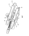
- FIGS. 1-5 an exemplary architecture for a robotic assembly 100 will now be discussed. Only a robotic arm portion of the robotic assembly 100 is shown in FIGS. 1-5 .
- the robotic arm 102 can be coupled to a vehicle base.
- Vehicle bases are well known in the art, and therefore will not be described herein. Any known or to be known vehicle base can be used herein without limitation.
- the robotic assembly 100 is configured to act as a robotic gripping mechanism for remote investigation of items and an explosive disruption mechanism for remotely disarming explosive devices (e.g., pipe bombs, letter bombs, hand grenades, land mines, etc.).
- the robotic gripping mechanism comprises a gripper 104 coupled to a distal end of the robotic arm 102.
- Grippers are well known in the art, and therefore will not be described herein. Any known or to be known gripper can be used herein without limitation.
- the explosive disruption mechanism comprises an Explosive Disruption Assembly ("EDA") 108 coupled to the robotic arm 102.
- the EDA 108 is coupled to the robotic arm via mounting structures 202.
- the mounting structures 202 may each comprise a plate 116 with apertures 204 formed therein.
- the apertures 204 are sized and shaped such that couplers (e.g., screws) can pass therethrough. The couplers secure the plate 116 to the robotic arm 102.
- the EDA 108 is shown as comprising three RPDs 110-114.
- the present invention is not limited in this regard. Any number of RPDs, physical size(s) of RPDs, and/or energy sizes of RPDs can be employed herein without limitation. Also, any type of RPD and/or combination of various types of RPDs can be employed herein without limitation.
- a first RPD may comprise a metal tube from which water is propelled, while a second RPD comprises a metal tube from which bullets are propelled.
- the EDA 108 also comprises a moving carrier 118 for the RPDs 110-114.
- the moving carrier 118 is configured to facilitate the deployment of the RPDs 110 -114 (as shown in FIG. 4 ) and the retraction of the RPDs 110-114 (as shown in FIGS. 1-3 and 5 ).
- the transition between the deployed/retraction positions of the RPDs 110-114 is achieved by causing the moving carrier 118 to travel linearly in directions 502, 504 along the length of the robotic arm 102.
- One way in which such linear movement of the moving carrier 118 is achieved will be discussed below in relation to FIGS. 6-8 .
- the EDA 108 further comprises a Recoil Absorption Mechanism ("RAM") 120 for the RPDs 110-114.
- the RAM 120 includes at least one spring 122, 124.
- the springs 122, 124 are shown as comprising constant force springs. Constant force springs are well known in the art, and therefore will not be described in detail herein. Still, it should be understood that the force exerted by each spring 122, 124 over its range of motion is a constant.
- the RAM 120 does not need to be tuned to handle a particular type of impulse created from weapons firing since the force transmitted to the robotic arm is constant. This feature of the RAM 120 facilitates the use of varying sizes/energy RPDs as described above.
- the spring 122, 124 is formed as a rolled ribbon of spring material (e.g., spring steel) such that it is relaxed when it is fully rolled up. As the spring 122, 124 is unrolled, the restoring force comes primarily from the portion of the ribbon near the roll. Because the geometry of that region remains nearly constant as the spring unrolls, the resulting force is nearly constant. The constant resulting force is an important feature of the springs 122, 124, which will become evident as the discussion progresses.
- spring material e.g., spring steel
- the springs 122, 124 can be arranged in various configurations relative to the RPDs 110-114.
- the springs 122, 124 are arranged such that a central axis 300 thereof is parallel to a horizontal plane defined by the RPDs 112, 114.
- the springs can alternatively be arranged to have a central axis that is perpendicular to the horizontal plane defined by the RPD, as shown in FIGS. 6-8 .
- the particular arrangement of the springs 122, 124 is maintained by: coupling a first end (not visible in the figures) thereof to a reel 126; and coupling the reel 126 to the moving carrier 118.
- the moving carrier 118 comprises upward extending flanges 302, 304 with apertures (not visible in the figures) formed therein.
- a rod 128 is disposed through the reel 126 and the aperture of the respective flange such that the reel 126 is rotatably coupled to the moving carrier 118.
- the rotatable coupling of the reel 126 to the moving carrier 118 allows the springs 122, 124 to be transitioned between their rolled positions shown in FIG. 4 and their unrolled positions shown in FIG. 1 .
- a second end 130 of each spring 122, 124 is attached to a stationary frame member 132 so as to enable the unrolling of the spring upon discharge of an RPD.
- the springs may comprise coil springs or helical springs for storing energy due to resilience and subsequently release the stored energy to absorb an impulse force caused by firing the RPDs 110-114.
- Coil springs are made of an elastic material which returns to its material length when unloaded. The force that is applied to a coil spring is proportional to the displacement of the coil spring. As such, the coil springs can decelerate the RPDs 110-114 and the moving carrier from some initial high velocity immediately after weapon firing down to zero at the end of spring travel. The force transmitted to the robotic arm from the coil springs increases as the displacement of the coil spring increases. As such, the force is not a constant force as is the case with the constant force springs.
- the constant force spring provides the lowest peak force transmitted to the robotic arm as compared to that of the coil spring. Also, the overall collapsed size of the coil spring is larger than that of the constant force spring. The coil spring may be deformed as a result of overloading thereof. Such deformation does not occur with the constant force springs.
- one or more sensors 506, 508 may be provided for detecting a location of the moving carrier 118 along the length of a rod 510. These sensors can facilitate the accurate placement of the RPDs 112, 114 relative to a suspicious item.
- the sensors 506, 508 can include, but are not limited to, switches or other sensors for detecting object without coming into contact with them. Any known or to be known sensor suitable for a particular application can be used herein without limitation.
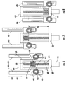
- FIGS. 6-8 there are shown schematic illustrations that are useful for understanding linear movement of a moving carrier (e.g., moving carrier 118 of FIGS. 1-5 ) relative to a robotic arm (not shown in FIGS. 6-8 ) and operations of a RAM (e.g., RAM 120 of FIGS. 1-5 ).
- Moving carrier 602 of FIGS. 6-8 can be the same as or similar to moving carrier 118 described above. As such, the discussion of moving carrier 602 is sufficient for understanding moving carrier 118 of FIGS. 1-5 .
- the RAM 620 of FIGS. 6-8 is similar to the RAM 120 described above. As such, the discussion of RAM 620 is sufficient for understanding RAM 120 of FIGS. 1-5 .
- the RAM 620 comprises springs 612 rolled on reels 622. The reels 622 are coupled to the moving carrier 602. An end 624 of each spring 612 is coupled to a stationary frame member 618.
- the direction that the RPDs 626, 628 point or aim is shown by arrow 650. So if one or more of the RPDs 626, 628 is fired, an impulse force is applied thereby against the moving carrier 602 in an impulse direction 652 (i.e., a direction opposite to that shown by arrow 650 ). When such an impulse force is applied to the moving carrier 602, it slides in the impulse direction 652 along rails 606. The sliding movement of the moving carrier 602 is facilitated by bearings 608.
- the rails 606 and bearings 608 are formed of materials that have a relatively low coefficient of friction.
- a Unidirectional Force Transfer (“UFT”) mechanism 610 is provided in the middle of the moving carrier 602 in the middle of the moving carrier 602.
- the UFT mechanism 610 comprises an aperture formed in the moving carrier 602 and a plurality of flexible fins 630 disposed along a sidewall of the aperture.
- the fins 630 engage threads of a rod 614 such that the moving carrier 602 is freely movable in the impulse direction 652 and prevented from moving in the firing direction 650 when a pushing force is applied thereto in said firing direction 650.
- the springs 612 are under tension at all times. In some scenarios, there is a 150 pound constant force pull from the springs 612. So when the RPDs 626, 628 are in their deployed positions shown in FIG. 7 , the springs 612 are pulling the moving carrier 602 towards the frame member 618. In effect, the fins 630 latch the moving carrier 602 in place so that movement of the carrier does not interfere with accurate aiming of the RPDs 626, 628 prior to and during firing thereof.
- the impulse force causes (1) a passive breakaway of the fins 630 and (2) the moving carrier 602 to slide along rails 606 is the impulse direction 652 until the RPDs 626, 628 reach their retracted positions shown in FIG. 8 .
- the impulse force is no longer being applied to the assembly.
- the moving carrier 602 is latched into position by the fins 630 and the pulling force of the springs 612.
- the stroke distance 700 is selected to ensure that all the energy from the RPD firing is stored in the springs 612. In some scenarios, the stroke distance 700 is selected to be about 10 inches.
- the force that is transferred to the robotic arm (e.g., robotic arm 102 of FIG. 1 ) via the frame member 618 is the constant pulling force of the springs 612.
- the relatively high impulse force of a few milliseconds is spread over a longer period of time as the moving carrier 602 slidingly travels in the impulse direction 652.
- the robotic arm does see force transmitted through to it, but such force is only a relatively small fraction of the impulse force (e.g., 1/10 of the impulse force that the RPD firing is producing on the moving carrier 602 ).
- the RPDs 626, 628 may be maintained in their retracted position until another firing thereof is desirable. In the retracted position, the RPDs 626, 628 do not interfere with operations of a robotic arm (e.g., robotic arm 102 of FIG. 1 ) to which the frame 604, 618 is attached.
- a robotic arm e.g., robotic arm 102 of FIG. 1
- the RPDs 626, 628 can be transitioned from their retracted position shown in FIG. 8 to their deployed position shown in FIG. 7 . Such a position transition is achieved by using a motor 616 with a gear head (not visible in FIGS. 6-8 ).
- the threaded rod 614 is turned in a direction for causing movement of moving carrier 602 in the firing directing 650.
- a reverse spin of the motor 616 will crank the moving carrier 602 back to the position shown in FIG. 8 .
- the threaded rod 614 may be replaced with another mechanical mechanism, such as a linear element with notches for latchingly engaging the fins 630.
- the motor may be configured to pull and push the linear notched element, as opposed to spin the same as is described above in relation to the threaded rod.
- UFT mechanism 512 of FIG. 5 and 610 of FIG. 6 are the same as or similar to UFT mechanism 900. As such, the discussion of UFT mechanism 900 is sufficient for understanding UFT mechanisms 610.
- the UFT mechanism 900 comprises a nut 1002 which can be thread onto a threaded rod 908 (e.g., threaded rod 614 of FIG. 6 ).
- the nut 1002 has been split in half and attached to a rigid support structure 902 via mechanical spring elements 1004-1006.
- the rigid support structure 902 comprises two apertures 904, 906 through which couplers (e.g., screws) can be inserted for attaching the rigid support structure 902 to a moving carrier.
- couplers e.g., screws
- FIG. 11 A schematic illustration showing the UFT mechanism 900 mechanically coupled to a moving carrier 1100 is provided in FIG. 11 .
- the moving carrier 1100 In response to an RPD firing, the moving carrier 1100 will slide in direction 1102, whereby the nut 1002 splits apart.
- the mechanical spring elements 1004-1006 (not visible in FIG. 11 ) push the two split nut portions towards each other.
- the threads of nut 1002 engage the threads of threaded rod 908. In effect, further movement of the moving carrier 1100 in direction 1104 is prevented.
- a motor can then be used to facilitate movement of the moving carrier 1100 in direction 1104, as described above.
- the present invention provides a mechanism for absorbing an impulsive load.
- the mechanism comprises: a fixed frame with a movable carrier (e.g., carrier 602 of FIG. 6 ) mounted to the frame via sliding elements (e.g., linear guide rods 606 of FIG. 6 ); springs (e.g., springs 612 of FIG. 6 ) attached at one end to the fixed frame (e.g., frame 618 of FIG. 6 ) and at the other end to a movable carrier; and a UFT element (e.g., UFT mechanism 610 of FIG. 6 or 900 of FIGS.
- a movable carrier e.g., carrier 602 of FIG. 6
- sliding elements e.g., linear guide rods 606 of FIG. 6
- springs e.g., springs 612 of FIG. 6
- UFT element e.g., UFT mechanism 610 of FIG. 6 or 900 of FIGS.
- the springs can include, but are not limited to, constant force springs.
- the latching element may be attached to a motor (e.g., motor 616 of FIG. 6 ) in such a way that the action of the motor moves the latching element, whereby the UFT element is displaced along the length of the latching element.
- the UFT element may comprise, but is not limited to, a split nut (e.g., nut 1002 of FIG. 10 ) attached to mechanical spring elements (e.g., mechanical springs 1004-1006 of FIG. 10 ). In all cases, the UFT element includes a set of angled flexible fins (e.g., fins 630 of FIG. 6 ).
- the robotic assembly of the present invention overcomes various drawbacks of conventional robotic assemblies, such as that disclosed in the background section of this document.
- the length ratio between the stroke length of the recoil absorbing mechanism and the total length of the recoil absorbing mechanism is significantly improved in the present invention as compared to that of the conventional robotic assemblies.
- the recoil absorbing mechanism of the present invention is much more compact as compared to conventional recoil absorbing mechanisms.
- a constant recoil force is ensured in the present invention by the constant force springs. This is not the case in conventional designs.
- conventional designs do not enable active retraction/deployment of the RPDs, and/or use of varying size/energy RPDs in a single compact design.
- a moving carrier e.g., moving carrier 118 of FIG. 1 , 602 of FIG. 6 or 1100 of FIG. 11
- a first direction e.g., direction 504 of FIG. 5 , 652 of FIG. 6 or 1102 if FIG. 11
- an RPD e.g., RPD 110, 112, 114 of FIG. 1 or 626, 628 of FIG. 6
- an impulse force resulting from the RPD discharge is absorbed using at least one spring (e.g., spring 122, 124 of FIG. 1 or 612 of FIG. 6 ).
- the spring can include, but is not limited to, a constant force spring or a coil spring. In both cases, the spring has a first end coupled to the moving carrier and a second end (e.g., end 130 of FIG. 1 ) to a fixed frame member (e.g., frame member 132 of FIG. 1 or 618 of FIG. 6 ). The spring applies a pulling force on the moving carrier in a second direction opposed from the first direction at the end of spring travel, as shown by step 1208.
- a uni-directional force transfer mechanism (e.g., UFT 512 of FIG. 5 , UFT 610 of FIG. 6 or 900 of FIG. 9 ) is caused to engage a rod (e.g., rod 510 of FIG. 5 , rod 614 of FIG. 6 or 908 of FIG. 9 ) so as to latch the moving carrier in position and prevent the moving carrier from freely traveling in the second direction.
- step 1212 is performed where the moving carrier is caused to travel linearly in the second direction by rotating the rod or pushing the rod in the second direction.
- the uni-directional force transfer mechanism is displaced along a length of the rod.
- step 1214 the position of the moving carrier is sensed along the length of the rod.
- step 1216 is performed where method 1200 ends or other actions are performed.
Landscapes
- Engineering & Computer Science (AREA)
- General Engineering & Computer Science (AREA)
- Toys (AREA)
Abstract
Description
- The inventive arrangements relate to recoil absorbing mechanism. More particularly, the inventive arrangements concern recoil absorbing mechanisms useful with Recoil Producing Devices ("RPDs"), such as energetic disruptors.
- There are various robotic platforms known in the art that comprise energetic disruptors (e.g., water jet disruptors) for inspecting and rendering threatening items (e.g., bombs) safe. Such robotic platforms are employed in various applications. Conventionally, robotic platforms have been used by police, bomb squads, and military personnel. Use of conventional energetic disruptors is difficult.
- In some cases, the deployment platform comprises a tripod-like assembly which needs to be manually placed near a suspicious item, whereby the operator is placed in harm's way. The tripod-like assembly has a limited set of firing locations and elevations.
- In other cases, the robotic platform comprises a movable arm to which the energetic disruptor is fixedly attached at a given location thereon. The movable arm does allow the energetic distruptor to be easily repositioned and aimed. However, the movable arm is over designed for all other applications of use thereof because it has to be strong enough to withstand the brief, high impulse load applied thereto when the energetic disruptor is shot. In effect, the robot is undesirably heavy and bulky. Also, the disruptor is attached to the movable arm so as to have a fixed position adjacent to a distal end thereof. In effect, the disruptor may interfere with other operations in which the movable arm is being employed. Additionally, the energetic disruptor applies a relatively high impulse load to the movable arm when shot. The high impulse load may cause damage to the movable arm.
- In yet other cases, the disruptor is mounted to a robotic arm with a recoil absorber. The recoil absorber does decrease the impulse load on the robot. However, the conventional recoil absorber designs are long and bulky. The amount of stroke in the conventional recoil absorber designs is relatively small in comparison to the overall bulk of the device. A lot of times, the robotic arm comprises a gripper at a distal end thereof. The disruptor may interfere with gripper operations and/or damage the gripper when shot.
- One conventional recoil absorber comprises a coil spring and damper. The damper is necessary to even out the shock load and dissipate energy. The issue with the spring/damper design is that: the damper adds an undesirable amount of weight and bulk to the design; and the design has a poor length ratio between the stroke length of the recoil absorber and the total length of the recoil absorber.
- The invention concerns implementing systems and methods for recoil absorption. The methods comprise causing a moving carrier to freely travel linearly in a first direction by discharging at least one RPD (e.g., a disruptor). An impulse force resulting from the RPD's discharge is absorbed using at least one spring (e.g., a constant force spring or a coil spring). The spring has a first end coupled to the moving carrier and a second end coupled to a fixed frame member. A pulling force is applied by the spring to the moving carrier in a second direction opposed from the first direction at an end of spring travel. Consequently, a uni-directional force transfer mechanism is caused to engage an elongate latching element (e.g., a threaded or notched rod) so as to latch the moving carrier in position and prevent the moving carrier from freely traveling in the second direction.
- The moving carrier can then be caused to travel linearly in the second direction by rotating the elongate latching element or pushing the elongate latching element in the second direction. Such rotation or pushing causes the uni-directional force transfer mechanism to be displaced along a length of the latching element.
- In some scenarios, the uni-directional force transfer mechanism comprises a split nut attached to a rigid support structure via mechanical spring elements. Additionally or alternatively, the uni-directional force transfer mechanism comprises a plurality of flexible fins engaging threads or notches formed along a length of the elongate latching element. A sensor may be provided to sense a position of the moving carrier along a length of the elongate latching element.
- Embodiments will be described with reference to the following drawing figures, in which like numerals represent like items throughout the figures, and in which:
-
FIG. 1 is a front perspective view of a robotic assembly with an RPD assembly in a retracted state. -
FIG. 2 is a side view of the robotic assembly shown inFIG. 1 . -
FIG. 3 is front view of the robotic assembly shown inFIGS. 1-2 . -
FIG. 4 is a front perspective view of the robotic assembly shown inFIGS. 1-3 with the RPD in a deployed state. -
FIG. 5 is a top view of the robotic assembly shown inFIGS. 1-4 with an RPD of the RPD assembly removed therefrom. -
FIGS. 6-8 provide schematic illustrations that are useful for understanding retraction and deployment operations of the RPD assembly shown inFIGS. 1-5 . -
FIGS. 9-10 provide schematic illustrations that are useful for understanding an exemplary architecture of a unidirectional force transfer mechanism. -
FIG. 11 provides a schematic illustration of the UFT mechanism shown inFIGS. 9-10 mechanically coupled to a moving carrier. -
FIG. 12 is a flow diagram of an exemplary method for recoil absorption. - It will be readily understood that the components of the embodiments as generally described herein and illustrated in the appended figures could be arranged and designed in a wide variety of different configurations. Thus, the following more detailed description of various embodiments, as represented in the figures, is not intended to limit the scope of the present disclosure, but is merely representative of various embodiments. While the various aspects of the embodiments are presented in drawings, the drawings are not necessarily drawn to scale unless specifically indicated.
- The present invention may be embodied in other specific forms without departing from its spirit or essential characteristics. The described embodiments are to be considered in all respects only as illustrative and not restrictive. The scope of the invention is, therefore, indicated by the appended claims rather than by this detailed description. All changes which come within the meaning and range of equivalency of the claims are to be embraced within their scope.
- Reference throughout this specification to features, advantages, or similar language does not imply that all of the features and advantages that may be realized with the present invention should be or are in any single embodiment of the invention. Rather, language referring to the features and advantages is understood to mean that a specific feature, advantage, or characteristic described in connection with an embodiment is included in at least one embodiment of the present invention. Thus, discussions of the features and advantages, and similar language, throughout the specification may, but do not necessarily, refer to the same embodiment.
- Furthermore, the described features, advantages and characteristics of the invention may be combined in any suitable manner in one or more embodiments. One skilled in the relevant art will recognize, in light of the description herein, that the invention can be practiced without one or more of the specific features or advantages of a particular embodiment. In other instances, additional features and advantages may be recognized in certain embodiments that may not be present in all embodiments of the invention.
- Reference throughout this specification to "one embodiment", "an embodiment", or similar language means that a particular feature, structure, or characteristic described in connection with the indicated embodiment is included in at least one embodiment of the present invention. Thus, the phrases "in one embodiment", "in an embodiment", and similar language throughout this specification may, but do not necessarily, all refer to the same embodiment.
- As used in this document, the singular form "a", "an", and "the" include plural references unless the context clearly dictates otherwise. Unless defined otherwise, all technical and scientific terms used herein have the same meanings as commonly understood by one of ordinary skill in the art. As used in this document, the term "comprising" means "including, but not limited to".
- The present invention concerns systems and methods for recoil absorption. The systems comprise a RPD coupled to a moving carrier. The term "RPD", as used herein, reference to any device that produces recoil. An example of such a device is a disruptor or a weapon from which something is propelled (e.g., water, bullets, shells, missiles, etc.). As a result of discharging the RPD device (e.g., a disruptor), a moving carrier is caused to freely travel linearly in a first direction. An impulse force resulting from the RPD's discharge is absorbed using at least one spring (e.g., a constant force spring or a coil spring). The spring has a first end coupled to the moving carrier and a second end coupled to a fixed frame member. A pulling force is applied by the spring to the moving carrier in a second direction opposed from the first direction at an end of spring travel. Consequently, a uni-directional force transfer mechanism is caused to engage an elongate latching element (e.g., a threaded or notched rod) so as to latch the moving carrier in position and prevent the moving carrier from freely traveling in the second direction. The moving carrier can then be caused to travel linearly in the second direction by rotating the elongate latching element or pushing the elongate latching element in the second direction. Such rotation or pushing causes the uni-directional force transfer mechanism to be displaced along a length of the latching element.
- Referring now to
FIGS. 1-5 , an exemplary architecture for arobotic assembly 100 will now be discussed. Only a robotic arm portion of therobotic assembly 100 is shown inFIGS. 1-5 . Therobotic arm 102 can be coupled to a vehicle base. Vehicle bases are well known in the art, and therefore will not be described herein. Any known or to be known vehicle base can be used herein without limitation. - The
robotic assembly 100 is configured to act as a robotic gripping mechanism for remote investigation of items and an explosive disruption mechanism for remotely disarming explosive devices (e.g., pipe bombs, letter bombs, hand grenades, land mines, etc.). The robotic gripping mechanism comprises agripper 104 coupled to a distal end of therobotic arm 102. Grippers are well known in the art, and therefore will not be described herein. Any known or to be known gripper can be used herein without limitation. - The explosive disruption mechanism comprises an Explosive Disruption Assembly ("EDA") 108 coupled to the
robotic arm 102. TheEDA 108 is coupled to the robotic arm via mounting structures 202. The mounting structures 202 may each comprise aplate 116 withapertures 204 formed therein. Theapertures 204 are sized and shaped such that couplers (e.g., screws) can pass therethrough. The couplers secure theplate 116 to therobotic arm 102. - The
EDA 108 is shown as comprising three RPDs 110-114. The present invention is not limited in this regard. Any number of RPDs, physical size(s) of RPDs, and/or energy sizes of RPDs can be employed herein without limitation. Also, any type of RPD and/or combination of various types of RPDs can be employed herein without limitation. For example, a first RPD may comprise a metal tube from which water is propelled, while a second RPD comprises a metal tube from which bullets are propelled. - The
EDA 108 also comprises a movingcarrier 118 for the RPDs 110-114. The movingcarrier 118 is configured to facilitate the deployment of the RPDs 110-114 (as shown inFIG. 4 ) and the retraction of the RPDs 110-114 (as shown inFIGS. 1-3 and5 ). The transition between the deployed/retraction positions of the RPDs 110-114 is achieved by causing the movingcarrier 118 to travel linearly indirections robotic arm 102. One way in which such linear movement of the movingcarrier 118 is achieved will be discussed below in relation toFIGS. 6-8 . - The
EDA 108 further comprises a Recoil Absorption Mechanism ("RAM") 120 for the RPDs 110-114. TheRAM 120 includes at least onespring springs spring RAM 120 does not need to be tuned to handle a particular type of impulse created from weapons firing since the force transmitted to the robotic arm is constant. This feature of theRAM 120 facilitates the use of varying sizes/energy RPDs as described above. - The
spring spring springs - The
springs FIGS. 1-5 , thesprings central axis 300 thereof is parallel to a horizontal plane defined by theRPDs FIGS. 6-8 . - The particular arrangement of the
springs reel 126; and coupling thereel 126 to the movingcarrier 118. In this regard, the movingcarrier 118 comprises upward extendingflanges rod 128 is disposed through thereel 126 and the aperture of the respective flange such that thereel 126 is rotatably coupled to the movingcarrier 118. The rotatable coupling of thereel 126 to the movingcarrier 118 allows thesprings FIG. 4 and their unrolled positions shown inFIG. 1 . Notably, asecond end 130 of eachspring stationary frame member 132 so as to enable the unrolling of the spring upon discharge of an RPD. - The present invention is not limited to constant force springs. Additionally or alternatively, the springs may comprise coil springs or helical springs for storing energy due to resilience and subsequently release the stored energy to absorb an impulse force caused by firing the RPDs 110-114. Coil springs are made of an elastic material which returns to its material length when unloaded. The force that is applied to a coil spring is proportional to the displacement of the coil spring. As such, the coil springs can decelerate the RPDs 110-114 and the moving carrier from some initial high velocity immediately after weapon firing down to zero at the end of spring travel. The force transmitted to the robotic arm from the coil springs increases as the displacement of the coil spring increases. As such, the force is not a constant force as is the case with the constant force springs. Thus, for a given amount of energy that needs to be absorbed from weapon firing, the constant force spring provides the lowest peak force transmitted to the robotic arm as compared to that of the coil spring. Also, the overall collapsed size of the coil spring is larger than that of the constant force spring. The coil spring may be deformed as a result of overloading thereof. Such deformation does not occur with the constant force springs.
- As shown in
FIG. 5 , one ormore sensors carrier 118 along the length of arod 510. These sensors can facilitate the accurate placement of theRPDs sensors - Referring now to
FIGS. 6-8 , there are shown schematic illustrations that are useful for understanding linear movement of a moving carrier (e.g., movingcarrier 118 ofFIGS. 1-5 ) relative to a robotic arm (not shown inFIGS. 6-8 ) and operations of a RAM (e.g.,RAM 120 ofFIGS. 1-5 ). Movingcarrier 602 ofFIGS. 6-8 can be the same as or similar to movingcarrier 118 described above. As such, the discussion of movingcarrier 602 is sufficient for understanding movingcarrier 118 ofFIGS. 1-5 . Similarly, theRAM 620 ofFIGS. 6-8 is similar to theRAM 120 described above. As such, the discussion ofRAM 620 is sufficient for understandingRAM 120 ofFIGS. 1-5 . TheRAM 620 comprisessprings 612 rolled onreels 622. Thereels 622 are coupled to the movingcarrier 602. Anend 624 of eachspring 612 is coupled to astationary frame member 618. - For purposes of understanding the following discussion, the direction that the
RPDs arrow 650. So if one or more of theRPDs carrier 602 in an impulse direction 652 (i.e., a direction opposite to that shown by arrow 650). When such an impulse force is applied to the movingcarrier 602, it slides in theimpulse direction 652 alongrails 606. The sliding movement of the movingcarrier 602 is facilitated bybearings 608. Therails 606 andbearings 608 are formed of materials that have a relatively low coefficient of friction. - In the middle of the moving
carrier 602, a Unidirectional Force Transfer ("UFT")mechanism 610 is provided. TheUFT mechanism 610 comprises an aperture formed in the movingcarrier 602 and a plurality of flexible fins 630 disposed along a sidewall of the aperture. The fins 630 engage threads of arod 614 such that the movingcarrier 602 is freely movable in theimpulse direction 652 and prevented from moving in thefiring direction 650 when a pushing force is applied thereto in saidfiring direction 650. - Notably, the
springs 612 are under tension at all times. In some scenarios, there is a 150 pound constant force pull from thesprings 612. So when theRPDs FIG. 7 , thesprings 612 are pulling the movingcarrier 602 towards theframe member 618. In effect, the fins 630 latch the movingcarrier 602 in place so that movement of the carrier does not interfere with accurate aiming of theRPDs - As a consequence of firing the
RPDs springs 612. In some cases, the impulse force is a few thousand pounds of pull force indirection 652, while the spring force is a few hundred pounds indirection 650. Therefore, the impulse force causes (1) a passive breakaway of the fins 630 and (2) the movingcarrier 602 to slide alongrails 606 is theimpulse direction 652 until theRPDs FIG. 8 . When theRPDs carrier 602 is latched into position by the fins 630 and the pulling force of thesprings 612. - As the moving
carrier 602 is sliding in theimpulse direction 652, the energy from the RPD firing is being absorbed by thesprings 612. Energy stored is defined mathematically as force times distance. As such, thestroke distance 700 is selected to ensure that all the energy from the RPD firing is stored in thesprings 612. In some scenarios, thestroke distance 700 is selected to be about 10 inches. - The force that is transferred to the robotic arm (e.g.,
robotic arm 102 ofFIG. 1 ) via theframe member 618 is the constant pulling force of thesprings 612. Thus, the relatively high impulse force of a few milliseconds is spread over a longer period of time as the movingcarrier 602 slidingly travels in theimpulse direction 652. The robotic arm does see force transmitted through to it, but such force is only a relatively small fraction of the impulse force (e.g., 1/10 of the impulse force that the RPD firing is producing on the moving carrier 602). - The
RPDs RPDs robotic arm 102 ofFIG. 1 ) to which theframe RPDs RPDs FIG. 8 to their deployed position shown inFIG. 7 . Such a position transition is achieved by using amotor 616 with a gear head (not visible inFIGS. 6-8 ). As themotor 616 spins the gear head, the threadedrod 614 is turned in a direction for causing movement of movingcarrier 602 in the firing directing 650. A reverse spin of themotor 616 will crank the movingcarrier 602 back to the position shown inFIG. 8 . - The present invention is not limited to the exemplary architecture shown in
FIGS. 6-8 . For example, the threadedrod 614 may be replaced with another mechanical mechanism, such as a linear element with notches for latchingly engaging the fins 630. In this case, the motor may be configured to pull and push the linear notched element, as opposed to spin the same as is described above in relation to the threaded rod. - Referring now to
FIGS. 9-10 , there are provided schematic illustrations that are useful for understanding an exemplary architecture of aUFT mechanism 900.UFT mechanism 512 ofFIG. 5 and 610 ofFIG. 6 are the same as or similar toUFT mechanism 900. As such, the discussion ofUFT mechanism 900 is sufficient for understandingUFT mechanisms 610. - As shown in
FIGS. 9-10 , theUFT mechanism 900 comprises anut 1002 which can be thread onto a threaded rod 908 (e.g., threadedrod 614 ofFIG. 6 ). Thenut 1002 has been split in half and attached to arigid support structure 902 via mechanical spring elements 1004-1006. Therigid support structure 902 comprises twoapertures rigid support structure 902 to a moving carrier. When therigid support structure 902 is mechanically coupled to the moving carrier, asurface 1008 of therigid support structure 902 abuts a surface of the moving carrier. In effect, when the threadedrod 908 is pushed in a direction towards the moving carrier, thenut 1002 will not split apart. However, when the threadedrod 908 is pulled in an opposite direction, thenut 1002 splits apart. Thenut 1002 re-engages with the threadedrod 908 upon termination of the pulling force. - A schematic illustration showing the
UFT mechanism 900 mechanically coupled to a movingcarrier 1100 is provided inFIG. 11 . In response to an RPD firing, the movingcarrier 1100 will slide indirection 1102, whereby thenut 1002 splits apart. When the movingcarrier 1100 stops traveling indirection 1102, the mechanical spring elements 1004-1006 (not visible inFIG. 11 ) push the two split nut portions towards each other. As the constant force springs pull the moving carrier indirection 1104, the threads ofnut 1002 engage the threads of threadedrod 908. In effect, further movement of the movingcarrier 1100 indirection 1104 is prevented. A motor can then be used to facilitate movement of the movingcarrier 1100 indirection 1104, as described above. - In view of the forgoing, the present invention provides a mechanism for absorbing an impulsive load. The mechanism comprises: a fixed frame with a movable carrier (e.g.,
carrier 602 ofFIG. 6 ) mounted to the frame via sliding elements (e.g.,linear guide rods 606 ofFIG. 6 ); springs (e.g., springs 612 ofFIG. 6 ) attached at one end to the fixed frame (e.g.,frame 618 ofFIG. 6 ) and at the other end to a movable carrier; and a UFT element (e.g.,UFT mechanism 610 ofFIG. 6 or 900 ofFIGS. 9-10 ) mounted to the moving carrier and interfacing with a latching element (e.g., threadedrod 614 ofFIG. 6 ). The springs can include, but are not limited to, constant force springs. The latching element may be attached to a motor (e.g.,motor 616 ofFIG. 6 ) in such a way that the action of the motor moves the latching element, whereby the UFT element is displaced along the length of the latching element. The UFT element may comprise, but is not limited to, a split nut (e.g.,nut 1002 ofFIG. 10 ) attached to mechanical spring elements (e.g., mechanical springs 1004-1006 ofFIG. 10 ). In all cases, the UFT element includes a set of angled flexible fins (e.g., fins 630 ofFIG. 6 ). - The robotic assembly of the present invention overcomes various drawbacks of conventional robotic assemblies, such as that disclosed in the background section of this document. For example, the length ratio between the stroke length of the recoil absorbing mechanism and the total length of the recoil absorbing mechanism is significantly improved in the present invention as compared to that of the conventional robotic assemblies. As such, the recoil absorbing mechanism of the present invention is much more compact as compared to conventional recoil absorbing mechanisms. Also, a constant recoil force is ensured in the present invention by the constant force springs. This is not the case in conventional designs. Furthermore, conventional designs do not enable active retraction/deployment of the RPDs, and/or use of varying size/energy RPDs in a single compact design.
- Referring now to
FIG. 12 , there is provided a flow diagram of anexemplary method 1200 for recoil absorption. Themethod 1200 begins withstep 1202 and continues withstep 1204. Instep 1204, a moving carrier (e.g., movingcarrier 118 ofFIG. 1 , 602 ofFIG. 6 or 1100 ofFIG. 11 ) is caused to freely travel in a first direction (e.g.,direction 504 ofFIG. 5 , 652 ofFIG. 6 or 1102 ifFIG. 11 ) by discharging an RPD (e.g.,RPD FIG. 1 or 626, 628 ofFIG. 6 ). Next instep 1206, an impulse force resulting from the RPD discharge is absorbed using at least one spring (e.g.,spring FIG. 1 or 612 ofFIG. 6 ). The spring can include, but is not limited to, a constant force spring or a coil spring. In both cases, the spring has a first end coupled to the moving carrier and a second end (e.g., end 130 ofFIG. 1 ) to a fixed frame member (e.g.,frame member 132 ofFIG. 1 or 618 ofFIG. 6 ). The spring applies a pulling force on the moving carrier in a second direction opposed from the first direction at the end of spring travel, as shown bystep 1208. In turn, a uni-directional force transfer mechanism (e.g.,UFT 512 ofFIG. 5 ,UFT 610 ofFIG. 6 or 900 ofFIG. 9 ) is caused to engage a rod (e.g.,rod 510 ofFIG. 5 ,rod 614 ofFIG. 6 or 908 ofFIG. 9 ) so as to latch the moving carrier in position and prevent the moving carrier from freely traveling in the second direction. Thereafter,step 1212 is performed where the moving carrier is caused to travel linearly in the second direction by rotating the rod or pushing the rod in the second direction. As a result of such rotating or pushing, the uni-directional force transfer mechanism is displaced along a length of the rod. Next inoptional step 1214, the position of the moving carrier is sensed along the length of the rod. Subsequently,step 1216 is performed wheremethod 1200 ends or other actions are performed. - All of the apparatus, methods and algorithms disclosed and claimed herein can be made and executed without undue experimentation in light of the present disclosure. While the invention has been described in terms of preferred embodiments, it will be apparent to those of skill in the art that variations may be applied to the apparatus, methods and sequence of steps of the method without departing from the concept, spirit and scope of the invention. More specifically, it will be apparent that certain components may be added to, combined with, or substituted for the components described herein while the same or similar results would be achieved. All such similar substitutes and modifications apparent to those skilled in the art are deemed to be within the spirit, scope and concept of the invention as defined.
Claims (10)
- A method for recoil assembly, comprising:causing a moving carrier to freely travel linearly in a first direction by discharging at least one Recoil Producing Device ("RPD");absorbing an impulse force resulting from discharging said RPD using at least one spring having a first end coupled to said moving carrier and a second end coupled to a fixed frame member; andapplying a pulling force by said spring to said moving carrier in a second direction opposed from said first direction at an end of spring travel, whereby a uni-directional force transfer mechanism is caused to engage an elongate latching element so as to latch said moving carrier in position and prevent said moving carrier from freely traveling in said second direction.
- The method according to claim 1, wherein said spring comprises a constant force spring.
- The method according to claim 1, further comprising transmitting a constant force to a robot from said spring when said impulse force is being absorbed by said spring.
- The method according to claim 1, wherein said latching element comprises a threaded rod.
- The method according to claim 1, further comprising causing said moving carrier to travel linearly in said second direction by rotating said elongate latching element or pushing said elongate latching element in said second direction.
- The method according to claim 1, further comprising causing said moving carrier to travel linearly in said second direction by displacing said uni-directional force transfer mechanism along a length of said latching element.
- The method according to claim 1, wherein said uni-directional force transfer mechanism comprises a split nut attached to a rigid support structure via mechanical spring elements.
- The method according to claim 1, wherein said uni-directional force transfer mechanism comprises a plurality of flexible fins engaging threads or notches formed along a length of said elongate latching element.
- The method according to claim 1, wherein said moving carrier is mechanically coupled to said RPD.
- The method according to claim 1, further comprising sensing a position of said moving carrier along a length of said elongate latching element.
Applications Claiming Priority (1)
| Application Number | Priority Date | Filing Date | Title |
|---|---|---|---|
| US14/450,869 US9506728B2 (en) | 2014-08-04 | 2014-08-04 | Recoil absorbing mechanism |
Publications (2)
| Publication Number | Publication Date |
|---|---|
| EP2982926A1 true EP2982926A1 (en) | 2016-02-10 |
| EP2982926B1 EP2982926B1 (en) | 2016-12-14 |
Family
ID=53432921
Family Applications (1)
| Application Number | Title | Priority Date | Filing Date |
|---|---|---|---|
| EP15001697.0A Active EP2982926B1 (en) | 2014-08-04 | 2015-06-08 | Recoil absorbing mechanism |
Country Status (2)
| Country | Link |
|---|---|
| US (1) | US9506728B2 (en) |
| EP (1) | EP2982926B1 (en) |
Families Citing this family (4)
| Publication number | Priority date | Publication date | Assignee | Title |
|---|---|---|---|---|
| CL2014002767A1 (en) * | 2014-10-15 | 2014-12-05 | Corporación Nac Del Cobre De Chile | Mechanical device for the arrangement and handling of an explosive cone adjustable to one arm, used in underground mining operations, comprises a grip system, an adjustment spring, a support plate, two thrust cylinders, a motor for rotation, a motor for tilt, a union support and a protective motor cover |
| WO2017200619A2 (en) * | 2016-02-24 | 2017-11-23 | Elsner Jeff | Firearm recoil control system |
| US10240885B2 (en) * | 2016-12-07 | 2019-03-26 | Harris Corporation | Shock absorbing disruptor mounting system |
| US10955212B2 (en) * | 2018-04-16 | 2021-03-23 | Eagle Technology, Llc | Lightweight recoil management |
Citations (3)
| Publication number | Priority date | Publication date | Assignee | Title |
|---|---|---|---|---|
| US20110000363A1 (en) * | 2007-04-02 | 2011-01-06 | More Industries, LLC | Mitigating recoil in a ballistic robot |
| US8276501B1 (en) * | 2010-08-06 | 2012-10-02 | The United States Of America As Represented By The Secretary Of The Army | Recoil dissipation apparatus |
| US8707846B2 (en) * | 2008-11-06 | 2014-04-29 | Rheinmetall Waffe Munition Gmbh | Weapon with recoil and braking device, damping this recoil |
Family Cites Families (35)
| Publication number | Priority date | Publication date | Assignee | Title |
|---|---|---|---|---|
| US789806A (en) * | 1902-03-25 | 1905-05-16 | Konrad Haussner | Recoiling gun. |
| US2790357A (en) * | 1952-09-16 | 1957-04-30 | Garrett Emil | Recoil mechanism for a mortar |
| US3004475A (en) * | 1953-04-28 | 1961-10-17 | Aircraft Armaments Inc | Rocket gun |
| US3672255A (en) * | 1965-02-23 | 1972-06-27 | Us Army | Equal impulse firearm |
| US3604308A (en) * | 1969-07-11 | 1971-09-14 | Us Army | Means for releasably latching a recoiling mass against counterrecoil movement |
| CA883176A (en) * | 1970-04-08 | 1971-10-12 | R. Schmidt Gilbert | Rifle zeroing device |
| FR2127224A5 (en) * | 1971-03-01 | 1972-10-13 | Int Vibration Engin | |
| US4088057A (en) | 1976-12-03 | 1978-05-09 | Remington Arms Company, Inc. | Recoil reducing and piston shock absorbing mechanism |
| DE2658770C2 (en) * | 1976-12-24 | 1983-12-08 | Rheinmetall GmbH, 4000 Düsseldorf | Device on an automatic barrel weapon to control the firing sequence (cadence) |
| US4261247A (en) * | 1979-05-30 | 1981-04-14 | The United States Of America As Represented By The Secretary Of The Army | Double action charging mechanism |
| US4476969A (en) * | 1982-04-12 | 1984-10-16 | Dykema Owen W | Dynamic recoil damping mechanism |
| US5014595A (en) * | 1988-09-16 | 1991-05-14 | Ducolon Jr Fredric D | Redirected recoil mechanism |
| DE3930256A1 (en) * | 1989-09-11 | 1991-03-14 | Rheinmetall Gmbh | TANK TOWER |
| US5811720A (en) * | 1997-06-16 | 1998-09-22 | Quinnell; Glenn D. | Shooting rest with recoil reduction system |
| CA2332017C (en) * | 1998-06-10 | 2007-09-25 | Proparms Ltd. | Liquid disrupter with reduced recoil |
| US6578464B2 (en) * | 2001-08-29 | 2003-06-17 | Battelle Memorial Institute | Recoil mitigation device |
| US6789456B2 (en) * | 2001-08-29 | 2004-09-14 | Battelle Memorial Institute | Braking system |
| US6802406B2 (en) * | 2002-12-17 | 2004-10-12 | United Defense, L.P. | Recoil brake isolation system |
| US7228778B2 (en) * | 2004-04-07 | 2007-06-12 | Terrell Edwards | Recoil reduction adapter |
| RO122108B1 (en) * | 2005-03-22 | 2008-12-30 | Vasile Cînciu | Butt for sporting gun without recoil |
| DE102006032300A1 (en) * | 2006-07-11 | 2008-01-17 | Peter Weiss | Device for disarming improvised explosive devices (IED) |
| US7997179B1 (en) * | 2008-04-01 | 2011-08-16 | The United States Of America As Represented By The Secretary Of The Navy | Hybrid water cannon |
| US8371425B2 (en) * | 2008-10-30 | 2013-02-12 | Ford Global Technologies, Llc | Dynamic displacement energy management device |
| US8297172B2 (en) * | 2008-11-12 | 2012-10-30 | Alliant Techsystems Inc. | Unmanned air vehicle weapon adapter |
| US8297174B1 (en) * | 2008-12-09 | 2012-10-30 | The United States Of America As Represented By The Secretary Of The Army | Apparatus and method for gun recoil mitigation |
| KR101276255B1 (en) | 2009-03-13 | 2013-06-20 | 아크시스템 일렉트로메카닉 사나이 베 티카렛 리미티드 에스티아이 | Triple action friction shock absorber |
| JP5518561B2 (en) * | 2010-04-28 | 2014-06-11 | 日立オートモティブシステムズ株式会社 | Shock absorber |
| IL206630A (en) | 2010-06-24 | 2016-11-30 | Soltam Systems Ltd | Energy absorber for firearms |
| US20130033056A1 (en) * | 2011-08-05 | 2013-02-07 | Tunis Iii George C | Energy absorbing system for blast mitigation of support elements such as suspended seats or stretchers in military vehicles |
| US8899141B2 (en) * | 2013-02-15 | 2014-12-02 | George L. Reynolds | Rate control mechanism |
| US9416842B2 (en) * | 2013-03-27 | 2016-08-16 | Honeywell International Inc. | Isolators having damper-external thermal compensators and spacecraft isolation systems employing the same |
| KR102050876B1 (en) * | 2013-05-06 | 2019-12-03 | 한화디펜스 주식회사 | Apparatus for supporting firearm, firearm assembly and method for reducing shock by gunshot |
| US9021728B1 (en) * | 2013-05-21 | 2015-05-05 | Edward Kocmich, IV | Firearm recoil return assembly |
| US20160102945A1 (en) * | 2013-12-19 | 2016-04-14 | Arnold Itzkowitz | Gyroscopically assisted weapon stabilization systems |
| US9435602B1 (en) * | 2015-01-14 | 2016-09-06 | The United States Of America As Represented By The Secretary Of The Army | Active recoil control system |
-
2014
- 2014-08-04 US US14/450,869 patent/US9506728B2/en active Active
-
2015
- 2015-06-08 EP EP15001697.0A patent/EP2982926B1/en active Active
Patent Citations (3)
| Publication number | Priority date | Publication date | Assignee | Title |
|---|---|---|---|---|
| US20110000363A1 (en) * | 2007-04-02 | 2011-01-06 | More Industries, LLC | Mitigating recoil in a ballistic robot |
| US8707846B2 (en) * | 2008-11-06 | 2014-04-29 | Rheinmetall Waffe Munition Gmbh | Weapon with recoil and braking device, damping this recoil |
| US8276501B1 (en) * | 2010-08-06 | 2012-10-02 | The United States Of America As Represented By The Secretary Of The Army | Recoil dissipation apparatus |
Also Published As
| Publication number | Publication date |
|---|---|
| US9506728B2 (en) | 2016-11-29 |
| EP2982926B1 (en) | 2016-12-14 |
| US20160033239A1 (en) | 2016-02-04 |
Similar Documents
| Publication | Publication Date | Title |
|---|---|---|
| EP2982926B1 (en) | Recoil absorbing mechanism | |
| US11085728B2 (en) | Crossbow with cabling system | |
| US10126088B2 (en) | Crossbow | |
| US10077965B2 (en) | Cocking system for a crossbow | |
| US10082359B2 (en) | Torque control system for cocking a crossbow | |
| US3572621A (en) | Shock mitigating spring and detent pedestal | |
| US20160161209A1 (en) | Elastic projectile propulsion systems and methods | |
| US8006981B2 (en) | Moving target system for defensive training | |
| US10800547B1 (en) | Unmanned aerial vehicle (UAV) recovery system | |
| JP2016502641A (en) | Elastically mounted armor panel | |
| US9303943B2 (en) | Stringed projectile weapon | |
| JP2010197098A (en) | Iceball launcher and hailstorm testing method | |
| US20230204319A1 (en) | Crossbow | |
| US11492141B2 (en) | Systems and methods for capturing and recovering unmanned aircraft | |
| EP3332924B1 (en) | Shock absorbing disruptor mounting system | |
| US6745663B2 (en) | Apparatus for mitigating recoil and method thereof | |
| US4587733A (en) | Percussion device | |
| US20150260475A1 (en) | Collapsible projectile launcher | |
| US3092210A (en) | Brake for airplane-arresting devices | |
| US10071810B1 (en) | Methods and apparatus for a parachute retainer | |
| US20140251295A1 (en) | Two-phase projectile | |
| US2427035A (en) | Shell handling device for trench mortars | |
| US3374865A (en) | Snubber for deploying lines | |
| US3410503A (en) | Damping device for towed air target bodies | |
| GB2218058A (en) | Launching system for acceleration-sensitive body |
Legal Events
| Date | Code | Title | Description |
|---|---|---|---|
| PUAI | Public reference made under article 153(3) epc to a published international application that has entered the european phase |
Free format text: ORIGINAL CODE: 0009012 |
|
| 17P | Request for examination filed |
Effective date: 20150608 |
|
| AK | Designated contracting states |
Kind code of ref document: A1 Designated state(s): AL AT BE BG CH CY CZ DE DK EE ES FI FR GB GR HR HU IE IS IT LI LT LU LV MC MK MT NL NO PL PT RO RS SE SI SK SM TR |
|
| AX | Request for extension of the european patent |
Extension state: BA ME |
|
| GRAP | Despatch of communication of intention to grant a patent |
Free format text: ORIGINAL CODE: EPIDOSNIGR1 |
|
| INTG | Intention to grant announced |
Effective date: 20160728 |
|
| STAA | Information on the status of an ep patent application or granted ep patent |
Free format text: STATUS: GRANT OF PATENT IS INTENDED |
|
| GRAS | Grant fee paid |
Free format text: ORIGINAL CODE: EPIDOSNIGR3 |
|
| GRAA | (expected) grant |
Free format text: ORIGINAL CODE: 0009210 |
|
| STAA | Information on the status of an ep patent application or granted ep patent |
Free format text: STATUS: THE PATENT HAS BEEN GRANTED |
|
| AK | Designated contracting states |
Kind code of ref document: B1 Designated state(s): AL AT BE BG CH CY CZ DE DK EE ES FI FR GB GR HR HU IE IS IT LI LT LU LV MC MK MT NL NO PL PT RO RS SE SI SK SM TR |
|
| REG | Reference to a national code |
Ref country code: GB Ref legal event code: FG4D |
|
| REG | Reference to a national code |
Ref country code: CH Ref legal event code: EP |
|
| REG | Reference to a national code |
Ref country code: IE Ref legal event code: FG4D |
|
| REG | Reference to a national code |
Ref country code: AT Ref legal event code: REF Ref document number: 853984 Country of ref document: AT Kind code of ref document: T Effective date: 20170115 |
|
| REG | Reference to a national code |
Ref country code: DE Ref legal event code: R096 Ref document number: 602015000943 Country of ref document: DE |
|
| PG25 | Lapsed in a contracting state [announced via postgrant information from national office to epo] |
Ref country code: LV Free format text: LAPSE BECAUSE OF FAILURE TO SUBMIT A TRANSLATION OF THE DESCRIPTION OR TO PAY THE FEE WITHIN THE PRESCRIBED TIME-LIMIT Effective date: 20161214 |
|
| REG | Reference to a national code |
Ref country code: LT Ref legal event code: MG4D |
|
| REG | Reference to a national code |
Ref country code: NL Ref legal event code: MP Effective date: 20161214 |
|
| PG25 | Lapsed in a contracting state [announced via postgrant information from national office to epo] |
Ref country code: GR Free format text: LAPSE BECAUSE OF FAILURE TO SUBMIT A TRANSLATION OF THE DESCRIPTION OR TO PAY THE FEE WITHIN THE PRESCRIBED TIME-LIMIT Effective date: 20170315 Ref country code: LT Free format text: LAPSE BECAUSE OF FAILURE TO SUBMIT A TRANSLATION OF THE DESCRIPTION OR TO PAY THE FEE WITHIN THE PRESCRIBED TIME-LIMIT Effective date: 20161214 Ref country code: NO Free format text: LAPSE BECAUSE OF FAILURE TO SUBMIT A TRANSLATION OF THE DESCRIPTION OR TO PAY THE FEE WITHIN THE PRESCRIBED TIME-LIMIT Effective date: 20170314 Ref country code: SE Free format text: LAPSE BECAUSE OF FAILURE TO SUBMIT A TRANSLATION OF THE DESCRIPTION OR TO PAY THE FEE WITHIN THE PRESCRIBED TIME-LIMIT Effective date: 20161214 |
|
| REG | Reference to a national code |
Ref country code: AT Ref legal event code: MK05 Ref document number: 853984 Country of ref document: AT Kind code of ref document: T Effective date: 20161214 |
|
| PG25 | Lapsed in a contracting state [announced via postgrant information from national office to epo] |
Ref country code: FI Free format text: LAPSE BECAUSE OF FAILURE TO SUBMIT A TRANSLATION OF THE DESCRIPTION OR TO PAY THE FEE WITHIN THE PRESCRIBED TIME-LIMIT Effective date: 20161214 Ref country code: RS Free format text: LAPSE BECAUSE OF FAILURE TO SUBMIT A TRANSLATION OF THE DESCRIPTION OR TO PAY THE FEE WITHIN THE PRESCRIBED TIME-LIMIT Effective date: 20161214 Ref country code: HR Free format text: LAPSE BECAUSE OF FAILURE TO SUBMIT A TRANSLATION OF THE DESCRIPTION OR TO PAY THE FEE WITHIN THE PRESCRIBED TIME-LIMIT Effective date: 20161214 |
|
| PG25 | Lapsed in a contracting state [announced via postgrant information from national office to epo] |
Ref country code: NL Free format text: LAPSE BECAUSE OF FAILURE TO SUBMIT A TRANSLATION OF THE DESCRIPTION OR TO PAY THE FEE WITHIN THE PRESCRIBED TIME-LIMIT Effective date: 20161214 |
|
| PG25 | Lapsed in a contracting state [announced via postgrant information from national office to epo] |
Ref country code: EE Free format text: LAPSE BECAUSE OF FAILURE TO SUBMIT A TRANSLATION OF THE DESCRIPTION OR TO PAY THE FEE WITHIN THE PRESCRIBED TIME-LIMIT Effective date: 20161214 Ref country code: CZ Free format text: LAPSE BECAUSE OF FAILURE TO SUBMIT A TRANSLATION OF THE DESCRIPTION OR TO PAY THE FEE WITHIN THE PRESCRIBED TIME-LIMIT Effective date: 20161214 Ref country code: RO Free format text: LAPSE BECAUSE OF FAILURE TO SUBMIT A TRANSLATION OF THE DESCRIPTION OR TO PAY THE FEE WITHIN THE PRESCRIBED TIME-LIMIT Effective date: 20161214 Ref country code: IS Free format text: LAPSE BECAUSE OF FAILURE TO SUBMIT A TRANSLATION OF THE DESCRIPTION OR TO PAY THE FEE WITHIN THE PRESCRIBED TIME-LIMIT Effective date: 20170414 Ref country code: SK Free format text: LAPSE BECAUSE OF FAILURE TO SUBMIT A TRANSLATION OF THE DESCRIPTION OR TO PAY THE FEE WITHIN THE PRESCRIBED TIME-LIMIT Effective date: 20161214 |
|
| PG25 | Lapsed in a contracting state [announced via postgrant information from national office to epo] |
Ref country code: SM Free format text: LAPSE BECAUSE OF FAILURE TO SUBMIT A TRANSLATION OF THE DESCRIPTION OR TO PAY THE FEE WITHIN THE PRESCRIBED TIME-LIMIT Effective date: 20161214 Ref country code: PL Free format text: LAPSE BECAUSE OF FAILURE TO SUBMIT A TRANSLATION OF THE DESCRIPTION OR TO PAY THE FEE WITHIN THE PRESCRIBED TIME-LIMIT Effective date: 20161214 Ref country code: BE Free format text: LAPSE BECAUSE OF FAILURE TO SUBMIT A TRANSLATION OF THE DESCRIPTION OR TO PAY THE FEE WITHIN THE PRESCRIBED TIME-LIMIT Effective date: 20161214 Ref country code: IT Free format text: LAPSE BECAUSE OF FAILURE TO SUBMIT A TRANSLATION OF THE DESCRIPTION OR TO PAY THE FEE WITHIN THE PRESCRIBED TIME-LIMIT Effective date: 20161214 Ref country code: ES Free format text: LAPSE BECAUSE OF FAILURE TO SUBMIT A TRANSLATION OF THE DESCRIPTION OR TO PAY THE FEE WITHIN THE PRESCRIBED TIME-LIMIT Effective date: 20161214 Ref country code: BG Free format text: LAPSE BECAUSE OF FAILURE TO SUBMIT A TRANSLATION OF THE DESCRIPTION OR TO PAY THE FEE WITHIN THE PRESCRIBED TIME-LIMIT Effective date: 20170314 Ref country code: PT Free format text: LAPSE BECAUSE OF FAILURE TO SUBMIT A TRANSLATION OF THE DESCRIPTION OR TO PAY THE FEE WITHIN THE PRESCRIBED TIME-LIMIT Effective date: 20170414 Ref country code: AT Free format text: LAPSE BECAUSE OF FAILURE TO SUBMIT A TRANSLATION OF THE DESCRIPTION OR TO PAY THE FEE WITHIN THE PRESCRIBED TIME-LIMIT Effective date: 20161214 |
|
| REG | Reference to a national code |
Ref country code: DE Ref legal event code: R097 Ref document number: 602015000943 Country of ref document: DE |
|
| PLBE | No opposition filed within time limit |
Free format text: ORIGINAL CODE: 0009261 |
|
| STAA | Information on the status of an ep patent application or granted ep patent |
Free format text: STATUS: NO OPPOSITION FILED WITHIN TIME LIMIT |
|
| 26N | No opposition filed |
Effective date: 20170915 |
|
| PG25 | Lapsed in a contracting state [announced via postgrant information from national office to epo] |
Ref country code: DK Free format text: LAPSE BECAUSE OF FAILURE TO SUBMIT A TRANSLATION OF THE DESCRIPTION OR TO PAY THE FEE WITHIN THE PRESCRIBED TIME-LIMIT Effective date: 20161214 |
|
| REG | Reference to a national code |
Ref country code: DE Ref legal event code: R119 Ref document number: 602015000943 Country of ref document: DE |
|
| PG25 | Lapsed in a contracting state [announced via postgrant information from national office to epo] |
Ref country code: MC Free format text: LAPSE BECAUSE OF FAILURE TO SUBMIT A TRANSLATION OF THE DESCRIPTION OR TO PAY THE FEE WITHIN THE PRESCRIBED TIME-LIMIT Effective date: 20161214 |
|
| PG25 | Lapsed in a contracting state [announced via postgrant information from national office to epo] |
Ref country code: SI Free format text: LAPSE BECAUSE OF FAILURE TO SUBMIT A TRANSLATION OF THE DESCRIPTION OR TO PAY THE FEE WITHIN THE PRESCRIBED TIME-LIMIT Effective date: 20161214 |
|
| REG | Reference to a national code |
Ref country code: IE Ref legal event code: MM4A |
|
| REG | Reference to a national code |
Ref country code: FR Ref legal event code: ST Effective date: 20180228 |
|
| PG25 | Lapsed in a contracting state [announced via postgrant information from national office to epo] |
Ref country code: DE Free format text: LAPSE BECAUSE OF NON-PAYMENT OF DUE FEES Effective date: 20180103 Ref country code: IE Free format text: LAPSE BECAUSE OF NON-PAYMENT OF DUE FEES Effective date: 20170608 Ref country code: LU Free format text: LAPSE BECAUSE OF NON-PAYMENT OF DUE FEES Effective date: 20170608 |
|
| PG25 | Lapsed in a contracting state [announced via postgrant information from national office to epo] |
Ref country code: FR Free format text: LAPSE BECAUSE OF NON-PAYMENT OF DUE FEES Effective date: 20170630 |
|
| PG25 | Lapsed in a contracting state [announced via postgrant information from national office to epo] |
Ref country code: MT Free format text: LAPSE BECAUSE OF NON-PAYMENT OF DUE FEES Effective date: 20170608 |
|
| REG | Reference to a national code |
Ref country code: CH Ref legal event code: PL |
|
| PG25 | Lapsed in a contracting state [announced via postgrant information from national office to epo] |
Ref country code: LI Free format text: LAPSE BECAUSE OF NON-PAYMENT OF DUE FEES Effective date: 20180630 Ref country code: CH Free format text: LAPSE BECAUSE OF NON-PAYMENT OF DUE FEES Effective date: 20180630 |
|
| PG25 | Lapsed in a contracting state [announced via postgrant information from national office to epo] |
Ref country code: HU Free format text: LAPSE BECAUSE OF FAILURE TO SUBMIT A TRANSLATION OF THE DESCRIPTION OR TO PAY THE FEE WITHIN THE PRESCRIBED TIME-LIMIT; INVALID AB INITIO Effective date: 20150608 |
|
| PG25 | Lapsed in a contracting state [announced via postgrant information from national office to epo] |
Ref country code: CY Free format text: LAPSE BECAUSE OF FAILURE TO SUBMIT A TRANSLATION OF THE DESCRIPTION OR TO PAY THE FEE WITHIN THE PRESCRIBED TIME-LIMIT Effective date: 20161214 |
|
| PG25 | Lapsed in a contracting state [announced via postgrant information from national office to epo] |
Ref country code: MK Free format text: LAPSE BECAUSE OF FAILURE TO SUBMIT A TRANSLATION OF THE DESCRIPTION OR TO PAY THE FEE WITHIN THE PRESCRIBED TIME-LIMIT Effective date: 20161214 |
|
| PG25 | Lapsed in a contracting state [announced via postgrant information from national office to epo] |
Ref country code: TR Free format text: LAPSE BECAUSE OF FAILURE TO SUBMIT A TRANSLATION OF THE DESCRIPTION OR TO PAY THE FEE WITHIN THE PRESCRIBED TIME-LIMIT Effective date: 20161214 |
|
| PG25 | Lapsed in a contracting state [announced via postgrant information from national office to epo] |
Ref country code: AL Free format text: LAPSE BECAUSE OF FAILURE TO SUBMIT A TRANSLATION OF THE DESCRIPTION OR TO PAY THE FEE WITHIN THE PRESCRIBED TIME-LIMIT Effective date: 20161214 |
|
| PGFP | Annual fee paid to national office [announced via postgrant information from national office to epo] |
Ref country code: GB Payment date: 20250627 Year of fee payment: 11 |