EP2982626A1 - Paper-guiding mechanism and image-forming device - Google Patents
Paper-guiding mechanism and image-forming device Download PDFInfo
- Publication number
- EP2982626A1 EP2982626A1 EP14778169.4A EP14778169A EP2982626A1 EP 2982626 A1 EP2982626 A1 EP 2982626A1 EP 14778169 A EP14778169 A EP 14778169A EP 2982626 A1 EP2982626 A1 EP 2982626A1
- Authority
- EP
- European Patent Office
- Prior art keywords
- paper
- guide
- side lock
- base member
- base
- Prior art date
- Legal status (The legal status is an assumption and is not a legal conclusion. Google has not performed a legal analysis and makes no representation as to the accuracy of the status listed.)
- Withdrawn
Links
- 239000011347 resin Substances 0.000 claims description 9
- 229920005989 resin Polymers 0.000 claims description 9
- 238000010586 diagram Methods 0.000 description 7
- 230000002401 inhibitory effect Effects 0.000 description 3
- 230000015572 biosynthetic process Effects 0.000 description 2
- 230000000694 effects Effects 0.000 description 1
- 238000012986 modification Methods 0.000 description 1
- 230000004048 modification Effects 0.000 description 1
Images





Classifications
-
- B—PERFORMING OPERATIONS; TRANSPORTING
- B65—CONVEYING; PACKING; STORING; HANDLING THIN OR FILAMENTARY MATERIAL
- B65H—HANDLING THIN OR FILAMENTARY MATERIAL, e.g. SHEETS, WEBS, CABLES
- B65H9/00—Registering, e.g. orientating, articles; Devices therefor
- B65H9/04—Fixed or adjustable stops or gauges
-
- B—PERFORMING OPERATIONS; TRANSPORTING
- B65—CONVEYING; PACKING; STORING; HANDLING THIN OR FILAMENTARY MATERIAL
- B65H—HANDLING THIN OR FILAMENTARY MATERIAL, e.g. SHEETS, WEBS, CABLES
- B65H1/00—Supports or magazines for piles from which articles are to be separated
- B65H1/04—Supports or magazines for piles from which articles are to be separated adapted to support articles substantially horizontally, e.g. for separation from top of pile
-
- B—PERFORMING OPERATIONS; TRANSPORTING
- B65—CONVEYING; PACKING; STORING; HANDLING THIN OR FILAMENTARY MATERIAL
- B65H—HANDLING THIN OR FILAMENTARY MATERIAL, e.g. SHEETS, WEBS, CABLES
- B65H2405/00—Parts for holding the handled material
- B65H2405/10—Cassettes, holders, bins, decks, trays, supports or magazines for sheets stacked substantially horizontally
- B65H2405/12—Parts to be handled by user
- B65H2405/121—Locking means
-
- B—PERFORMING OPERATIONS; TRANSPORTING
- B65—CONVEYING; PACKING; STORING; HANDLING THIN OR FILAMENTARY MATERIAL
- B65H—HANDLING THIN OR FILAMENTARY MATERIAL, e.g. SHEETS, WEBS, CABLES
- B65H2511/00—Dimensions; Position; Numbers; Identification; Occurrences
- B65H2511/10—Size; Dimensions
- B65H2511/12—Width
-
- B—PERFORMING OPERATIONS; TRANSPORTING
- B65—CONVEYING; PACKING; STORING; HANDLING THIN OR FILAMENTARY MATERIAL
- B65H—HANDLING THIN OR FILAMENTARY MATERIAL, e.g. SHEETS, WEBS, CABLES
- B65H2511/00—Dimensions; Position; Numbers; Identification; Occurrences
- B65H2511/20—Location in space
Definitions
- the present invention relates to a paper guiding mechanism and an image forming device, and more particularly, it relates to a paper guiding mechanism and an image forming device each including a slidingly movable paper guide member.
- a paper guiding mechanism including a slidingly movable paper guide member is known in general. Such a paper guiding mechanism is disclosed in Japanese Patent Laying-Open No. 7-285681 , for example.
- a paper feed cassette (a paper guiding mechanism) including a paper placing plate (a base member) including a placing surface for placing papers thereon and a lock groove (a base-side lock portion) provided to extend in a prescribed direction along the placing surface and a paper guide member mounted to be slidingly movable in the prescribed direction with respect to the paper placing plate.
- a paper cassette includes a guide portion (a paper aligning portion) formed to extend in an upper direction with respect to the placing surface of the paper placing plate for coming into contact with edge portions of the papers placed on the placing surface of the paper placing plate.
- the paper cassette includes a pressing lever having a lock projection (a guide-side lock portion) locked to the lock groove of the paper placing plate.
- An elastic portion held by two notches extending in the upper direction with respect to the placing surface of the paper placing portion is formed on the guide portion.
- the guide portion and the pressing lever portion are configured to be connected with each other through the elastic portion.
- This paper cassette is configured to upwardly lift the lock projection on the lower portion of the pressing lever for canceling a locked state of the lock projection with respect to the lock groove by inclining the pressing lever toward the guide portion when placing large-sized papers.
- the paper cassette is configured to be adjustable to a size suiting the large-sized papers through the guide portion slidingly moved to the side of the pressing lever in an unlocked state where the aforementioned locked state is canceled.
- Patent Document 1 Japanese Patent Laying-Open No. 7-285681
- the present invention has been proposed in order to solve the aforementioned problem, and one object of the present invention is to provide a paper guiding mechanism and an image forming device each capable of smoothly moving a paper guide member to a side where large-sized papers are placeable with respect to a base member.
- a paper guiding mechanism includes a base member including a placing surface for placing papers thereon and a base-side lock portion provided to extend in a prescribed direction along the placing surface and a paper guide member mounted to be slidingly movable in the prescribed direction with respect to the base member, while the paper guide member includes a paper aligning portion formed to extend in an upper direction with respect to the placing surface of the base member for coming into contact with edge portions of the papers placed on the placing surface of the base member, a guide-side lock portion formed on a lower portion of the paper aligning portion to be locked to the base-side lock portion of the base member and an unlocking maintaining portion canceling a locked state of the guide-side lock portion with respect to the base-side lock portion by upwardly lifting the paper aligning portion provided with the guide-side lock portion on the lower portion and maintaining an unlocked state when the paper aligning portion is slidingly moved in the unlocked state where the locked state is canceled.
- the guide-side lock portion formed on the lower portion of the paper aligning portion to be locked to the base-side lock portion of the base member and the unlocking maintaining portion canceling the locked state of the guide-side lock portion with respect to the base-side lock portion by upwardly lifting the paper aligning portion provided with the guide-side lock portion on the lower portion and maintaining the unlocked state when the paper aligning portion is slidingly moved in the unlocked state where the locked state is canceled are so provided that it is possible to inhibit the guide-side lock portion upwardly lifted by the unlocking maintaining portion from lowering and hitting the base-side lock portion (to maintain the unlocked state) when the paper guide member is slidingly moved to a side where large-sized papers are placeable, whereby the guide-side lock portion of the paper guide member and the base-side lock portion of the base member can be inhibited from being caught by each other.
- the paper guide member can be smoothly moved to the side where large-sized papers are placeable with respect to the base member. Consequently, operability of the paper guide member can be improved.
- the guide-side lock portion locked to the base-side lock portion of the base member is so provided on the lower portion of the paper aligning portion that locking of the guide-side lock portion and the base-side lock portion can be inhibited from being canceled due to deformation of an elastic portion caused by a load from the papers in the locked state also in a case where the number of placed papers is large or in a case where the papers are firm (stiff), dissimilarly to a case of providing the guide-side lock portion on a lower portion of the unlocking maintaining portion from the paper aligning portion through the elastic portion.
- the paper guide member can be inhibited from slipping off in the locked state.
- the unlocking maintaining portion includes a lever portion having a lift portion upwardly lifting the paper aligning portion provided with the guide-side lock portion on the lower portion by inclining while coming into contact with the base member and a grasp portion grasped when inclining the lift portion while bringing the lift portion into contact with the base member, and a contact portion of the lift portion coming into contact with the base member when the lever portion inclines is arranged downward beyond a lower end of the guide-side lock portion in the unlocked state.
- the paper aligning portion provided with the guide-side lock portion on the lower portion can be easily upwardly lifted by moving the lift portion downward beyond the lower end of the guide-side lock portion with the lever portion (the grasp portion), whereby operability at the time of lifting up the paper aligning portion can be improved. Further, an interval between the guide-side lock portion of the lifted paper guide member and the base-side lock portion of the base member can be maintained due to the contact portion of the lift portion, whereby the guide-side lock portion and the base-side lock portion can be reliably inhibited from being caught by each other.
- the contact portion of the lift portion is arranged on a position separating to an outer side opposite to a side of the paper aligning portion coming into contact with the papers beyond the guide-side lock portion.
- force in a sliding movement direction applied to the paper aligning portion can be received by the contact portion of the lift portion when slidingly moving the paper aligning portion toward the outer side (the side where large-sized papers are placeable) opposite to the side of the paper aligning portion coming into contact with the papers beyond the guide-side lock portion, whereby the guide-side lock portion can be effectively inhibited from lowering and hitting the base-side lock portion.
- the grasp portion is arranged to be opposed to the paper aligning portion in the locked state, and an upper portion of the grasp portion inclines in a direction approaching the paper aligning portion and comes into contact with the paper aligning portion while the lift portion coming into contact with the base member inclines following inclination of the grasp portion thereby lifting up the guide-side lock portion in the unlocked state, and the contact portion of the lift portion coming into contact with the base member is slidingly movable in a state maintaining a prescribed angle of inclination with respect to the base portion in the unlocked state.
- the paper guide member is slidingly moved while the state where the contact portion of the lift portion inclines by the prescribed angle of inclination with respect to the base member at the time when the guide-side lock portion is lifted up is maintained, whereby the interval between the lifted guide-side lock portion and the base-side lock portion can be more reliably maintained also at the time of slidingly moving the paper guide member.
- the guide-side lock portion of the paper guide member and the base-side lock portion of the base member can be more reliably inhibited from being caught by each other.
- the paper guide member is slidingly movable in a state where the contact portion maintains the prescribed angle of inclination with respect to the base member while the paper aligning portion, the lift portion and the grasp portion maintain relative positional relation in the unlocked state.
- the paper guide member is slidingly moved while the state where the contact portion of the lift portion inclines by the prescribed angle of inclination with respect to the base member and the relative positional relation between the paper aligning portion, the lift portion and the grasp portion at the time when the guide-side lock portion is lifted up are maintained, whereby the interval between the lifted guide-side lock portion and the base-side lock portion can be more reliably maintained also at the time of slidingly moving the paper guide member.
- the guide-side lock portion of the paper guide member and the base-side lock portion of the base member can be more reliably inhibited from being caught by each other.
- the paper aligning portion, the grasp portion and the lift portion have thicknesses substantially undeformed in the unlocked state.
- the paper guide member can be slidingly moved in such a state that the state where the contact portion of the lift portion inclines by the prescribed angle of inclination with respect to the base member and the relative positional relation between the paper aligning portion, the lift portion and the grasp portion at the time when the guide-side lock portion is lifted up are reliably maintained.
- the guide-side lock portion of the paper guide member includes a guide-side pawl portion whose forward end has a prescribed angle, and the lift portion inclines by an angle smaller than the prescribed angle of the guide-side pawl portion with respect to the base member in the unlocked state.
- the lift portion can be inhibited from excessively inclining with respect to the base member in the unlocked state, whereby the lift portion (the lever portion) can be inhibited from being caught by the base member when slidingly moving the paper guide member.
- the base-side lock portion of the base member includes a base-side pawl portion
- the guide-side lock portion of the paper guide member includes a guide-side pawl portion
- the paper aligning portion is upwardly lifted to be arranged on a height position where the guide-side pawl portion of the guide-side lock portion does not come into contact with the base-side pawl portion of the base-side lock portion in the unlocked state.
- the lifted guide-side lock portion (the guide-side pawl portion) and the base-side lock portion (the base-side pawl portion) can be reliably inhibited from being caught by each other when slidingly moving the paper guide member.
- the grasp portion shifts the locked state to the unlocked state by being inclined toward the side of the paper aligning portion while bringing the lift portion into contact with the base member and shifts the unlocked state to the locked state by being separated from the side of the paper aligning portion and arranged substantially perpendicularly with respect to the base member.
- the unlocked state and the locked state can be easily switched by changing the inclined state of the grasp portion with respect to the paper aligning portion.
- the lever portion is formed substantially in an L shape by the lift portion positioned on a lower portion and the grasp portion extending in an upper direction intersecting with respect to the lift portion
- the paper guide member includes a connecting portion connecting the lever portion formed substantially in the L shape and the paper aligning portion with each other, and a torsion-deformable lever support portion pivotably supporting the lever portion is provided on a region of the connecting portion in the vicinity of the lever portion, while the lift portion of the lever portion pivots on the lever support portion to lift up the paper aligning portion and is inclined in the unlocked state.
- the lever portion can be easily inclined (pivoted) by torsion-deforming the lever support portion, whereby the paper aligning portion provided with the guide-side lock portion on the lower portion can be more easily upwardly lifted.
- a surface of the lift portion on the side of the base member is formed in a plate shape substantially in the form of a planar surface.
- the lever support portions are provided in a pair, and the pair of lever support portions hold the lever portion therebetween in plan view.
- the lever portion can be inclined in a stable state by torsion-deforming the pair of lever support portions.
- the lever support portion has a width smaller than the width of the connecting portion in plan view.
- the lever support portion can be easily torsion-deformed, whereby the lever portion can be more easily inclined.
- the paper guide member is formed by resin, and the paper aligning portion, the connecting portion and the lever portion are integrally formed.
- the paper aligning portion, the connecting portion and the lever portion can be easily simultaneously integrally formed by resin formation.
- the paper guide member further includes a load portion provided adjacently to the paper aligning portion to be loaded with the papers and a back surface arrangement portion provided to couple to the load portion and arranged on a back surface of the base member, and a hinge portion deflection-deformable in a direction for upwardly lifting the load portion and the paper aligning portion is provided in the vicinity of the boundary between the back surface arrangement portion and the load portion.
- a hinge portion deflection-deformable in a direction for upwardly lifting the load portion and the paper aligning portion is provided in the vicinity of the boundary between the back surface arrangement portion and the load portion.
- the back surface arrangement portion has a horizontally long shape extending in a direction where the paper aligning portion slidingly moves, and at least parts of the lift portion and the grasp portion are arranged to overlap with the back surface arrangement portion in a short-side direction of the back surface arrangement portion having the horizontally long shape.
- the back surface arrangement portion can be inhibited from being distorted around a straight line passing through the back surface arrangement portion and substantially parallel to the extensional direction of the back surface arrangement portion, dissimilarly to a case where the lift portion and the grasp portion are arranged on positions remarkably separating from the back surface arrangement portion in the short-side direction of the back surface arrangement portion.
- a vicinity of the hinge portion of the back surface arrangement portion can be easily upwardly deflected.
- the back surface arrangement portion includes a first restriction portion and a second restriction portion capable of restricting lifting of the paper aligning portion provided with the guide-side lock portion on the lower portion beyond a prescribed height by coming into contact with the back surface of the base member, the first restriction portion is formed on a position closer to the hinge portion than the second restriction portion, and an upper surface of the first restriction portion is arranged upward beyond an upper surface of the second restriction portion.
- the back surface arrangement portion can be inhibited from breakage due to excessive upward lifting of the paper aligning portion through the first restriction portion and the second restriction portion.
- the paper aligning portion is upwardly lifted by the difference between the heights of the upper surface of the first restriction portion and the upper surface of the second restriction portion, whereby the quantity of lifting of the paper aligning portion can be easily restricted.
- the base-side lock portion of the base member includes a base-side pawl portion
- the guide-side lock portion of the paper guide member includes a guide-side pawl portion
- the first restriction portion comes into contact with the base member in the locked state and the unlocked state
- the second restriction portion is arranged on a position between the first restriction portion and the guide-side pawl portion of the paper guide member in a direction where the paper aligning portion slidingly moves, and the interval between the upper surface of the first restriction portion and the upper surface of the second restriction portion is larger than the length of the base-side pawl portion in the vertical direction.
- the paper aligning portion can be easily upwardly lifted by the difference between the heights of the upper surface of the first restriction portion and the upper surface of the second restriction portion by employing the first restriction portion as the fulcrum, dissimilarly to a case where the second restriction portion is arranged on a side opposite to the first restriction portion beyond the guide-side pawl portion of the paper guide member.
- the first restriction portion and the second restriction portion are formed integrally with the back surface arrangement portion.
- the number of components can be reduced, dissimilarly to a case of structuring the first restriction portion and the second restriction portion separately from the back surface arrangement portion.
- An image forming device includes a printing portion performing printing on papers, a base member including a placing surface for placing the papers thereon and a base-side lock portion provided to extend in a prescribed direction along the placing surface and a paper guide member mounted to be slidingly movable in the prescribed direction with respect to the base member, while the paper guide member includes a paper aligning portion formed to extend in an upper direction with respect to the placing surface of the base member for coming into contact with edge portions of the papers placed on the placing surface of the base member, a guide-side lock portion formed on a lower portion of the paper aligning portion to be locked to the base-side lock portion of the base member, and an unlocking maintaining portion canceling a locked state of the guide-side lock portion with respect to the base-side lock portion by upwardly lifting the paper aligning portion provided with the guide-side lock portion on the lower portion and maintaining an unlocked state when the paper aligning portion is slidingly moved in the unlocked state where the locked state is canceled.
- the guide-side lock portion formed on the lower portion of the paper aligning portion to be locked to the base-side lock portion of the base member and the unlocking maintaining portion canceling the locked state of the guide-side lock portion with respect to the base-side lock portion by upwardly lifting the paper aligning portion provided with the guide-side lock portion on the lower portion and maintaining the unlocked state when the paper aligning portion is slidingly moved in the unlocked state where the locked state is canceled are so provided that it is possible to inhibit the guide-side lock portion upwardly lifted by the unlocking maintaining portion from lowering and hitting the base-side lock portion (to maintain the unlocked state) when the paper guide member is slidingly moved to a side where large-sized papers are placeable, whereby the guide-side lock portion of the paper guide member and the base-side lock portion of the base member can be inhibited from being caught by each other.
- the paper guide member can be smoothly moved to the side where large-sized papers are placeable with respect to the base member. Consequently, operability of the paper guide member can be improved.
- the guide-side lock portion locked to the base-side lock portion of the base member is so provided on the lower portion of the paper aligning portion that locking of the guide-side lock portion and the base-side lock portion can be inhibited from being canceled due to deformation of an elastic portion caused by a load from the papers in the locked state also in a case where the number of placed papers is large or in a case where the papers are firm (stiff), dissimilarly to a case of providing the guide-side lock portion on a lower portion of the unlocking maintaining portion from the paper aligning portion through the elastic portion.
- the paper guide member can be inhibited from slipping off in the locked state.
- the paper guide member can be smoothly moved toward the side where large-sized papers are placeable with respect to the base member.
- the structure of a printer device 100 according to the embodiment of the present invention is described with reference to Figs. 1 to 11 .
- the printer device 100 is an example of the "image forming device" in the present invention.
- the printer device 100 includes a base member 1 for placing papers 200 thereon, a paper guide member 2 for aligning the directions of the papers 200 and a developing device 3 performing printing on the papers 200, as shown in Fig. 1 .
- the developing device 3 includes a photosensitive drum for performing printing by sticking toner to the papers 200, a transfer roller for transferring the toner adhering to the photosensitive drum to the papers and the like.
- the papers 200 placed on the paper guide member 2 are configured to be transported to the developing device 3.
- the developing device 3 is an example of the "printing portion" in the present invention.
- a paper guiding mechanism 110 is constituted of the base member 1 and the paper guide member 2, a shown in Figs. 1 and 2 .
- the paper guiding mechanism 110 is configured to be mountable in the inner portion of the printer device 100.
- the base member 1 includes a placing surface 11 for placing the papers 200 thereon and a base-side lock portion 12 provided to extend in a Y direction along the placing surface 11, as shown in Fig. 2 .
- the placing surface 11 is so configured that the papers 200 of a prescribed size are placeable thereon.
- the base-side lock portion 12 includes a plurality of pawl portions 12a, as shown in Figs. 8 and 10 .
- the pawl portions 12a are so formed that sections thereof have substantially triangular shapes as viewed from an X direction.
- the pawl portions 12a have a length (a height) L in a Z direction.
- the base member 1 includes a rotary portion 13 including a pinion portion 13a on a back surface (the side of a Z2 direction), as shown in Fig. 3 .
- the rotary portion 13 includes a pair of projecting portions 13b in the diametral direction.
- the pawl portions 12a are examples of the "base-side pawl portion" in the present invention.
- the paper guide member 2 is configured to be mounted to be slidingly movable in the Y direction with respect to the base member 1, as shown in Fig. 2 .
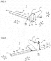
- the paper guide member 2 includes a paper aligning portion 21 aligning the directions of the papers 200 and a guide-side lock portion 22 (see Fig. 7 ) locked to the base-side lock portion 12 (see Fig. 2 ) of the base member 1, as shown in Figs. 4 to 7 .
- the paper guide member 2 includes a lever portion 23 canceling a locked state of the guide-side lock portion 22 with respect to the base-side lock portion 12.
- the paper guide member 2 includes connecting portions 24 connecting the lever portion 23 and the paper aligning portion 21 with each other.
- Lever support portions 25 are provided on regions between the connecting portions 24 and the lever portion 23. Further, the paper guide member 2 includes a load portion 26 loaded with the papers 200 and a back surface arrangement portion 27 arranged on the back surface (the side of the Z2 direction) of the base member 1.
- the paper guide member 2 is integrally formed by resin.
- the paper aligning portion 21 is formed to extend in an upper direction (a Z1 direction) substantially perpendicularly with respect to the placing surface 11 (see Fig. 2 ) of the base member 1, as shown in Figs. 4 to 7 . Further, the paper aligning portion 21 is configured to come into contact with edge portions of the papers 200 placed on the placing surface 11 of the base member 1, as shown in Fig. 2 .
- a floating inhibiting portion 21a inhibiting the papers 200 placed on the placing surface 11 of the base member 1 from floating up is provided on the upper side (the side of the Z1 direction) of the paper aligning portion 21, as shown in Figs. 2 , 4 and 5 .
- One guide-side lock portion 22 is formed on a lower portion (the side of the Z2 direction) of the paper aligning portion 21, as shown in Figs. 7 and 8 . Further, the guide-side lock portion 22 is configured to be locked to the base-side lock portion 12 of the base member 1, as shown in Fig. 8 . In addition, the guide-side lock portion 22 is formed on a position corresponding to the base-side lock portion 12 of the base member 1. Further, the guide-side lock portion 22 is provided in the form of a pawl. In other words, the guide-side lock portion 22 functions as a guide-side pawl portion whose forward end has a prescribed angle ⁇ 0 (see Fig. 10 ). The prescribed angle ⁇ 0 is a sharp angle.
- the guide-side lock portion 22 is formed to be substantially triangular as viewed from the X direction. Further, the guide-side lock portion 22 has the length L in the Z direction. In addition, the guide-side lock portion 22 is so configured that movement in a direction (a Y1 direction) for adjusting the paper guide member 2 with respect to large-sized papers is restricted. On the other hand, the guide-side lock portion 22 is so configured that movement in a direction (a Y2 direction) for adjusting the paper guide member 2 with respect to small-sized papers is possible.
- the lever portion 23 includes a lift portion 23a positioned on a lower portion (the side of the Z2 direction) and a grasp portion 23b extending in the upper direction (the Z1 direction) intersecting with respect to the lift portion 23a, as shown in Figs. 4 to 11 . Further, the lever portion 23 is formed substantially in an L shape. More specifically, a surface (a lower surface in a locked state) of the lift portion 23a of the lever portion 23 on the side of the base member 1 is formed in a plate shape substantially in the form of a planar surface. The lift portion 23a and the grasp portion 23b are configured to intersect with each other at an angle of about 90 degrees. The lever portion 23 is arranged on a Y1-direction side of the paper aligning portion 21.
- lever portion 23 is configured to switch the guide-side lock portion 22 from the locked state (see Fig. 8 ) to the unlocked state (see Fig. 10 ) by being inclined toward the left side (the side of the Y2 direction).
- the lever portion 23 is an example of the "unlocking maintaining portion" in the present invention.
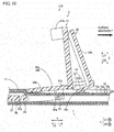
- the lift portion 23a is configured to upwardly lift the paper aligning portion 21 provided with the guide-side lock portion 22 on the lower portion (the side of the Z2 direction) by inclining while coming into contact with the base member 1, as shown in Figs. 10 and 11 . Further, the lift portion 23a is so configured that a contact portion 23c of the lift portion 23a coming into contact with the base member 1 is arranged on a position separating to an outer side opposite (in the Y1 direction) to a side of the paper aligning portion 21 coming into contact with the papers beyond the guide-side lock portion 22 when the lever portion 23 inclines (pivots).
- the grasp portion 23b is configured to be arranged to be opposed to the paper aligning portion 21 in the locked state where the guide-side lock portion 22 and the base-side lock portion 12 of the base member 1 are locked to each other. Further, the grasp portion 23b is configured to be grasped when inclining the lift portion 23a while bringing the same into contact with the base member 1.
- the lift portion 23a is an example of the "unlocking maintaining portion” in the present invention.
- the grasp portion 23b is an example of the "unlocking maintaining portion” in the present invention.
- the lever portion 23 is configured to cancel the locked state of the guide-side lock portion 22 with respect to the base-side lock portion 12 by lifting the paper aligning portion 21 provided with the guide-side lock portion 22 on the lower portion (the side of the Z2 direction) upward (in the Z1 direction), as shown in Fig. 10 . More specifically, the lever portion 23 is so configured that an upper portion of the grasp portion 23b inclines in a direction (the Y2 direction) approaching the paper aligning portion 21 to come into contact with the paper aligning portion 21 in the unlocked state. Further, the lever portion 23 is so configured that the lift portion 23a coming into contact with the base member 1 inclines following inclination of the grasp portion 23b so that the guide-side lock portion 22 is lifted up.
- the paper aligning portion 21 is upwardly lifted to be arranged on a height position where the guide-side lock portion 22 (the guide-side pawl portion) in the form of a pawl does not come into contact with the pawl portions 12a of the base-side lock portion 12 in the unlocked state.
- the paper guide member 2 is so configured that the lift portion 23a of the lever portion 23 pivots on the lever support portions 25 (see Fig. 4 ) to lift up the paper aligning portion 21 to be inclined in the unlocked state, as shown in Fig. 10 .
- the guide-side lock portion 22 is configured to be lifted up to a height where the locking with the base-side lock portion 12 of the base member 1 is canceled at this time.
- the lever portion 23 is configured to maintain the unlocked state when the paper aligning portion 21 is slidingly moved in the unlocked state.
- the paper guide member 2 is configured to be slidingly movable in a state where the contact portion 23c of the lift portion 23a coming into contact with the base member 1 maintains a prescribed angle ⁇ of inclination with respect to the base member 1 in the unlocked state, as shown in Figs. 10 and 11 . Further, the paper guide member 2 is configured to be slidingly movable in a state where the contact portion 23c maintains the prescribed angle ⁇ of inclination with respect to the base member 1 while the paper aligning portion 21, the lift portion 23a and the grasp portion 23b maintain relative positional relation in the unlocked state.
- the lift portion 23a inclines by the angle ⁇ smaller than the prescribed angle ⁇ 0 of the guide-side lock portion 22 (the guide-side pawl portion) with respect to the base member 1 in the unlocked state.
- the connecting portions 24 are provided in a pair between the paper aligning portion 21 and the lever portion 23, as shown in Figs. 4 and 7 . Further, the connecting portions 24 are provided in the form of plates.
- the lift portion 23a (see Fig. 4 ) is configured to be arranged between the pair of connecting portions 24.
- the paper aligning portion 21, the connecting portions 24 and the lever portion 23 are integrally formed by resin.
- the connecting portions 24 are formed substantially parallelly with respect to the base-side lock portion 12 and the placing surface 11 of the base member 1, as shown in Figs. 8 and 9 .
- the lever support portions 25 are provided as shown in Figs. 4 to 7 , and on regions of the connecting portions 24 in the vicinity of the lever portion 23. More specifically, the lever support portions 25 are provided in a pair between the connecting portions 24 and the lever portion 23. The pair of lever support portions 25 are configured to hold the lever portion 23 therebetween in plan view. Further, the lever support portions 25 have a width smaller than the width of the connecting portions 24 in plan view. Thus, the lever support portions 25 are configured to pivotably support the lever portion 23. Further, the lever support portions 25 are configured to be torsion-deformable when the lever portion 23 is inclined (pivoted).
- the lever support portions 25 have a width W2, smaller than a width W1 of the connecting portions 24 in the X direction, in the Y direction, as shown in Fig. 6 .
- the paper aligning portion 21, the lever portion 23 (the lift portion 23a and the grasp portion 23b), the connecting portions 24 and the load portion 26 are configured not to torsion-deform when the lever portion 23 is inclined (pivoted). More specifically, the paper aligning portion 21, the lever portion 23 (the lift portion 23a and the grasp portion 23b), the connecting portions 24 and the load portion 26 are formed to have prescribed thicknesses not torsion-deforming when the lever portion 23 is inclined (pivoted), in response to the resin constituting the paper guide member 2.
- This paper guiding mechanism 110 is configured to shift the locked state to the unlocked state by inclining the grasp portion 23b toward the side of the paper aligning portion 21 (the side of the Y2 direction) (bringing the grasp portion 23b into contact with the side of the paper aligning portion 21) while bringing the lift portion 23a into contact with the base member 1. Further, the paper guiding mechanism 110 is so configured that the grasp portion 23b is separated from the paper aligning portion 21 and arranged substantially perpendicularly with respect to the base member 1 thereby shifting the unlocked state to the locked state.
- the load portion 26 is provided to be adjacent to a surface of the paper aligning portion 21 on the side of the Y2 direction, as shown in Figs. 4 to 7 . Further, the load portion 26 is so configured that an upper surface 26a is substantially parallel with respect to the placing surface 11 of the base member 1, as shown in Figs. 8 and 9 .
- the back surface arrangement portion 26 is provided to couple to a lower surface 26b (see Fig. 7 ) of the load portion 26, as shown in Figs. 4 to 7 . Further, the back surface arrangement portion 27 is configured to be arranged (see Fig. 3 ) on the back surface (the side of the Z2 direction) of the base member 1. In addition, the back surface arrangement portion 27 is formed in a substantially horizontally long shape extending toward the direction (the Y direction) where the paper aligning portion 21 slidingly moves.
- the lever portion 23 (the lift portion 23a and the grasp portion 23b) is arranged in the vicinity of a straight line 500 (see Fig.
- the back surface arrangement portion 27 includes the hinge portion 28 which is deflection-deformable as well as first restriction portions 29 (see Fig. 7 ) and second restriction portions 30 (see Fig. 7 ) restricting a height up to which the paper aligning portion 21 is lifted.
- the back surface arrangement portion 27 includes a rack portion 31 having a plurality of pawl portions 31a on a side along the X2 direction.
- the back surface arrangement portion 27 includes a plurality of recess portions 32, as shown in Figs. 3 and 7 .
- the hinge portion 28 is provided in the vicinity of the boundary between the back surface arrangement portion 27 and the load portion 26, as shown in Figs. 4 to 7 .
- the hinge portion 28 is formed by lessening the width of the back surface arrangement portion 27 in the X direction.
- the hinge portion 28 is configured to be deflection-deformable in the direction lifting the load portion 26 and the paper aligning portion 21 upward (in the Z1 direction).
- the back surface arrangement portion 27 is so configured that a vicinity of the hinge portion 28 of the back surface arrangement portion 27 is deflected when the paper aligning portion 21 is upwardly lifted.
- the first restriction portions 29 and the second restriction portions 30 are configured to be capable of restricting lifting of the paper aligning portion 21 provided with the guide-side lock portion 22 on the lower portion beyond a prescribed height by coming into contact with the back surface (the side of the Z2 direction) of the base member 1, as shown in Figs. 8 to 11 .
- the first restriction portions 29 and the second restriction portions 30 are formed in single pairs respectively, as shown in Fig. 7 .
- the pair of first restriction portions 29 are formed on positions opposed to each other. Further, the pair of first restriction portions 29 are formed to protrude toward the X1 direction and the X2 direction respectively.
- the pair of second restriction portions 30 are formed on positions opposed to each other. Further, the pair of second restriction portions 30 are formed to protrude toward the X1 direction and the X2 direction respectively.
- the first restriction portions 29 and the second restriction portions 30 are formed integrally with the back surface arrangement portion 27.
- the first restriction portions 29 are formed on positions closer to the hinge portion 28 than the second restriction portions 30, as shown in Figs. 8 to 11 .
- Upper surfaces 29a of the first restriction portions 29 are formed to be arranged upward (the side of the Z1 direction) beyond upper surfaces 30a of the second restriction portions 30 in the locked state, as shown in Figs. 8 and 9 .
- the first restriction portions 29 are configured to come into contact with the lower surface (the surface on the side of the Z2 direction) of the base member 1 in the locked state and the unlocked state.
- the second restriction portions 30 are arranged on positions between the first restriction portions 29 and the guide-side lock portion 22 (the guide-side pawl portion) of the paper guide member 21 in the direction (the Y direction) where the paper aligning portion 21 slidingly moves.
- the first restriction portions 29 and the second restriction portions 30 are so formed that the upper surfaces 29a of the first restriction portions 29 and the upper surfaces 30a of the second restriction portions 30 separate from each other by a prescribed interval D, as shown in Figs. 8 and 9 . Further, the first restriction portions 29 and the second restriction portions 30 are so configured that the prescribed interval D between the upper surfaces 29a of the first restriction portions 29 and the upper surfaces 30a of the second restriction portions 30 is larger than the length L of the guide-side lock portion 22 and the base-side lock portion 12 (the pawl portions 12a) in the Z direction, as shown in Fig. 8 .
- the back surface arrangement portion 27 is so configured that the vicinity of the hinge portion 28 is deflection-deformable around the first restriction portions 29 serving as the fulcrums, as shown in Figs. 10 and 11 .
- the guide-side lock portion 22 (the paper aligning portion 21) is configured to be upwardly movable by a distance D in the unlocked state.
- the rack portion 31 is so configured that the plurality of pawl portions 31a are provided along the Y direction of the back surface arrangement portion 27, as shown in Figs. 4 to 7 . Further, the rack portion 31 is configured to fit with the pinion portion 13a (see Fig. 3 ) of the rotary portion 13 of the base member 1.
- the recess portions 32 are provided on the side of the back surface arrangement portion 27 in the Z2 direction, as shown in Figs. 3 and 7 . Further, the recess portions 32 are provided on side of the back surface arrangement portion 27 in the X2 direction.
- the paper guide member 2 is so configured that the recess portions 32 are fitted with the projecting portions 13b of the rotary portion 13 of the base member 1 thereby inhibiting the paper guide member 2 from deviating from a position adjusted to suit to a prescribed paper size, as shown in Fig. 3 .
- the grasp portion 23b (the lever portion 23) is inclined toward the side of the paper adjusting portion 21 (the side of the Y2 direction) in the unlocked state, as shown in Figs. 10 and 11 .
- the lift portion 23a is inclined with respect to the base member 1 following the inclination of the grasp portion 23b, whereby the guide-side lock portion 22 is lifted up.
- the contact portion 23c of the lift portion 23a coming into contact with the base member 1 when the grasp portion 23b inclines is arranged downward (the side of the Z2 direction) beyond the lower end of the guide-side lock portion 22.
- the guide-side lock portion 22 is switched from the locked state ( Figs. 8 and 9 ) to the unlocked state.
- the paper guide member 2 is slidingly moved in the Y1 direction by a user.
- the paper guide member 2 is slidingly moved in the Y1 direction in a state where the contact portion 23c of the lift portion 23a maintains the prescribed angle ⁇ of inclination with respect to the base member 1 while the paper aligning portion 21, the lift portion 23a and the grasp portion 23b maintain the relative positional relation.
- the upwardly lifted guide-side lock portion 22 can be inhibited from lowering and hitting the base-side lock portion 12 when the paper guide member 22 is slidingly moved to a side where large-sized papers are placeable, whereby the guide-side lock portion 22 and the base-side lock portion 12 can be inhibited from being caught by each other. Consequently, the paper guide member 2 can be smoothly moved to the side where large-sized papers are placeable with respect to the base member 1, and operability of the paper guide member 2 can be improved. Further, the guide-side lock portion 22 locked to the base-side lock portion 12 of the base member 1 is provided on the lower portion of the paper aligning portion 21.
- locking of the guide-side lock portion 22 and the base-side lock portion 12 can be inhibited from being canceled due to deformation of an elastic portion caused by a load from the papers 200 in the locked state also in a case where the number of placed papers is large or in a case where the papers are firm (stiff), dissimilarly to a case of including the guide-side lock portion 22 provided in the vicinity of the elastic portion.
- the paper guide member 2 can be inhibited from slipping off in the locked state.
- the paper aligning portion 21 provided with the guide-side lock portion 22 can be easily upwardly lifted by moving the lift portion 23a downward beyond the lower end of the guide-side lock portion 22 with the lever portion 23 (the grasp portion 23b), whereby operability at the time of lifting up the paper aligning portion 21 can be improved.
- the interval between the guide-side lock portion 22 of the lifted paper guide member 2 and the base-side lock portion 12 of the base member 1 can be maintained due to the contact portion 23c of the lift portion 23a, whereby the guide-side lock portion 22 and the base-side lock portion 12 can be reliably inhibited from being caught by each other.
- the contact portion 23c of the lift portion 23a is arranged on the position separating to the outer side opposite to the side of the paper aligning portion 21 coming into contact with the papers 200 beyond the guide-side lock portion 22.
- force in a sliding movement direction applied to the paper aligning portion 21 can be received by the contact portion 23c of the lift portion 23a when slidingly moving the paper aligning portion 22 to the outer side opposite to the side of the paper aligning portion 21 coming into contact with the papers 200 beyond the guide-side lock portion 22, whereby the guide-side lock portion 22 can be effectively inhibited from lowering and hitting the base-side lock portion 12.
- the grasp portion 23b is so configured that the same is opposed to the paper aligning portion 21 in the locked state and the upper portion inclines in the direction approaching the paper aligning portion 21 to come into contact with the paper aligning portion 21 in the unlocked state, while the guide-side lock portion is configured to be lifted up through such an operation that the lift portion 23a coming into contact with the base member 1 inclines following the inclination of the grasp portion 23b.
- the paper guide member 2 is slidingly moved while the state where the contact portion 23c of the lift portion 23a inclines by the prescribed angle of inclination with respect to the base member 1 at the time when the guide-side lock portion 22 is lifted up is maintained, whereby the interval between the lifted guide-side lock portion 22 and the base-side lock portion 12 can be more reliably maintained also at the time of slidingly moving the paper guide member 2. Consequently, the guide-side lock portion 22 and the base-side lock portion 12 can be more reliably inhibited from being caught by each other.
- the paper guide member 2 is configured to be slidingly movable in the state where the contact portion 23c maintains the prescribed angle of inclination with respect to the base member 1 while the paper aligning portion 21, the lift portion 23a and the grasp portion 23b maintain the relative positional relation in the unlocked state.
- the paper guide member 2 is slidingly moved while the state where the contact portion 23c of the lift portion 23a inclines by the prescribed angle of inclination with respect to the base member 1 and the relative positional relation between the paper aligning portion 21, the lift portion 23a and the grasp portion 23b at the time when the guide-side lock portion 22 is lifted up are maintained, whereby the interval between the lifted guide-side lock portion 22 and the base-side lock portion 12 can be further reliably maintained also at the time of slidingly moving the paper guide member 2.
- the guide-side lock portion 22 and the base-side lock portion 12 can be further reliably inhibited from being caught by each other.
- the paper aligning portion 21, the grasp portion 23b and the lift portion 23a are configured to have thicknesses substantially undeformed in the unlocked state.
- the paper guide member 22 can be slidingly moved in a state where the state where the contact portion 23c of the lift portion 23a inclines by the prescribed angle ⁇ of inclination with respect to the base member 1 and the relative positional relation between the paper aligning portion 21, the lift portion 23a and the grasp portion 23b at the time when the guide-side lock portion 22 is lifted up are reliably maintained.
- the guide-side lock portion 22 is so configured that the forward end has the prescribed angle ⁇ 0 and functions as the guide-side pawl portion, while the lift portion 23a is configured to incline by the angle ⁇ smaller than the prescribed angle ⁇ 0 of the guide-side pawl portion with respect to the base member 1 in the unlocked state.
- the lift portion 23a can be inhibited from excessively inclining with respect to the base member 11 in the unlocked state, whereby the lift portion 23a (the lever portion 23) can be inhibited from being caught by the base member 1 when slidingly moving the paper guide member 2.
- the upwardly lifted paper aligning portion 21 is configured to be arranged on the height position where the guide-side lock portion 22 does not come into contact with the pawl portions 12a of the base-side lock portion 12 in the unlocked state.
- the lifted guide-side lock portion 22 (the guide-side pawl portion) and the base-side lock portion 12 (the pawl portions 12a) can be reliably inhibited from being caught by each other when slidingly moving the paper guide member 2.
- the grasp portion 23b is configured to shift the locked state to the unlocked state by inclining toward the side of the paper aligning portion 21 while bringing the lift portion 23a into contact with the base member 1. Further, the grasp portion 23b is configured to shift the unlocked state to the locked state by being separated from the side of the paper aligning portion 21 and arranged substantially perpendicularly with respect to the base member 1. Thus, the unlocked state and the locked state can be easily switched by changing the inclined state of the grasp portion 23b with respect to the paper aligning portion 21.
- the lever portion 23 is formed substantially in an L shape
- the connecting portions 24 connecting the substantially L-shaped lever portion 23 and the paper aligning portion 21 with each other are provided on the paper guide member 2
- the torsion-deformable lever support portions 25 pivotably supporting the lever portion 23 are provided on the regions of the connecting portions 24 in the vicinity of the lever portion 23, and the lift portion 23a is configured to pivot and incline to lift up the paper aligning portion 21 on the lever support portions 25 in the unlocked state.
- the lever portions 23 can be easily inclined (pivoted) by torsion-deforming the lever support portions 25, whereby the paper aligning portion 21 provided with the guide-side lock portion 22 on the lower portion can be more easily upwardly lifted.
- the surface of the lift portion 23a on the side of the base member 1 is formed in a plate shape substantially in the form of a planar surface.
- friction between the surface of the lift portion 23a on the side of the base member 1 and the base member 1 can be reduced, whereby the paper guide member 2 can be smoothly slidingly moved.
- the pair of lever support portions 25 are configured to hold the lever portion 23 therebetween in plan view.
- the lever portion 23 can be inclined in a stable state by torsion-deforming the pair of lever support portions 25.
- the lever support portions 25 are configured to have the width smaller than the width of the connecting portions 24 in plan view.
- the lever support portions 25 can be easily torsion-deformed, whereby the lever portion 23 can be more easily inclined.
- the paper guide member 2 is formed by resin, and the paper aligning portion 21, the connecting portions 24 and the lever portion 23 are integrally formed.
- increase in the number of components can be suppressed, dissimilarly to a case of providing the paper aligning portion 21, the connecting portions 24 and the lever portion 23 separately from each other respectively.
- the paper aligning portion 21, the connecting portions 24 and the lever portion 23 can be easily simultaneously integrally formed by resin formation.
- the load portion 26 and the back surface arrangement portion 27 provided to couple to the load portion 26 are provided on the paper guide member 2, while the deflection-deformable hinge portion 28 is provided in the vicinity of the boundary between the back surface arrangement portion 27 and the load portion 26.
- the paper aligning portion 21 provided with the guide-side lock portion 22 on the lower portion can be easily upwardly lifted by deflecting a vicinity of the hinge portion 28 of the back surface arrangement portion 27.
- the back surface arrangement portion 27 is formed in the horizontally long shape extending in the direction where the paper aligning portion 21 slidingly moves, while parts of the lift portion 23a and the grasp portion 23b are arranged to overlap with the back surface arrangement portion 27 in the short-side direction (the X direction) of the back surface arrangement portion 27 of the horizontally long shape.
- the back surface arrangement portion 27 can be inhibited from getting distorted around the straight line 500 passing through the back surface arrangement portion 27 and substantially parallel to the extensional direction of the back surface arrangement portion 27, dissimilarly to a case where the lift portion 23a and the grasp portion 23b are arranged on positions remarkably separating from the back surface arrangement portion 27 in the short-side direction of the back surface arrangement portion 27.
- the vicinity of the hinge portion 28 of the back surface arrangement portion 27 can be easily upwardly deflected.
- the first restriction portions 29 and the second restriction portions 30 capable of restricting lifting of the paper aligning portion 21 provided with the guide-side lock portion 22 beyond the prescribed height are provided on the back surface arrangement portion 27, the first restriction portions 29 are formed on the positions closer to the hinge portion 28 than the second restriction portions 30, and the upper surfaces 29a of the first restriction portions 29 are arranged upward beyond the upper surfaces 30a of the second restriction portions 30.
- the back surface arrangement portion 27 can be inhibited from breakage due to excessive upward lifting of the paper aligning portion 21 through the first restriction portions 29 and the second restriction portions 30.
- the paper aligning portion 21 is upwardly lifted by the difference between the heights of the upper surfaces 29a of the first restriction portions 29 and the upper surfaces 30a of the second restriction portions 30, whereby the quantity of lifting of the paper aligning portion 21 can be easily restricted.
- the first restriction portions 29 are configured to come into contact with the base member 1 in the locked state and the unlocked state
- the second restriction portions 30 are arranged on the positions between the first restriction portions 29 and the guide-side lock portion 22 (the guide-side pawl portion) in the direction where the paper aligning portion 21 slidingly moves
- the interval D between the upper surfaces of the first restriction portions 29 and the upper surfaces of the second restriction portions 30 is configured to be larger than the length L of the pawl portions 12a in the vertical direction.
- the paper aligning portion 21 can be easily upwardly lifted by the difference between the heights of the upper surfaces of the first restriction portions 29 and the upper surfaces of the second restriction portions 30 by employing the first restriction portions 29 as the fulcrums, dissimilarly to a case where the second restriction portions 30 are arranged on a side opposite to the first restriction portions 29 beyond the guide-side lock portion 22 (the guide-side pawl portion).
- the first restriction portions 29 and the second restriction portions 30 are formed integrally with the back surface arrangement portion 27.
- the number of components can be reduced, dissimilarly to a case of structuring the first restriction portions 29 and the second restriction portions 30 separately from the back surface arrangement portion 27.
- the present invention is not restricted to this.
- the present invention may be applied to a paper guiding mechanism and an image forming device other than the printer device.
- the present invention may be applied to a paper guiding mechanism such as a scanner, or an image forming device such as a facsimile.
- the present invention is not restricted to this.
- the locked state may be canceled and the unlocked state may be maintained with an unlocking maintaining portion other than the lever portion.
- the section of the lever portion (the unlocking maintaining portion) has the substantially L shape
- the present invention is not restricted to this.
- the section of the unlocking maintaining portion may have a substantially triangular shape, for example, other than the substantially L shape.
- rigidity of the unlocking maintaining portion can be further increased, whereby force applied to the paper aligning portion can be reliably received when the paper guide member is slidingly moved. Consequently, the lifted guide-side lock portion can be further reliably inhibited from lowering.
- the present invention is not restricted to this. According to the present invention, the paper aligning portion, the connecting portions and the unlocking maintaining portion may not be integrally formed.
- the hinge portion may be formed by lessening the width of the back surface arrangement portion in the vertical direction (the Z direction).
Landscapes
- Engineering & Computer Science (AREA)
- Mechanical Engineering (AREA)
- Sheets, Magazines, And Separation Thereof (AREA)
- Pile Receivers (AREA)
Abstract
Description
- The present invention relates to a paper guiding mechanism and an image forming device, and more particularly, it relates to a paper guiding mechanism and an image forming device each including a slidingly movable paper guide member.
- A paper guiding mechanism including a slidingly movable paper guide member is known in general. Such a paper guiding mechanism is disclosed in Japanese Patent Laying-Open No.
7-285681 - In the aforementioned Japanese Patent Laying-Open No.
7-285681 - Patent Document 1: Japanese Patent Laying-Open No.
7-285681 - In the paper cassette according to the aforementioned Japanese Patent Laying-Open No.
7-285681 - The present invention has been proposed in order to solve the aforementioned problem, and one object of the present invention is to provide a paper guiding mechanism and an image forming device each capable of smoothly moving a paper guide member to a side where large-sized papers are placeable with respect to a base member.
- A paper guiding mechanism according to a first aspect of the present invention includes a base member including a placing surface for placing papers thereon and a base-side lock portion provided to extend in a prescribed direction along the placing surface and a paper guide member mounted to be slidingly movable in the prescribed direction with respect to the base member, while the paper guide member includes a paper aligning portion formed to extend in an upper direction with respect to the placing surface of the base member for coming into contact with edge portions of the papers placed on the placing surface of the base member, a guide-side lock portion formed on a lower portion of the paper aligning portion to be locked to the base-side lock portion of the base member and an unlocking maintaining portion canceling a locked state of the guide-side lock portion with respect to the base-side lock portion by upwardly lifting the paper aligning portion provided with the guide-side lock portion on the lower portion and maintaining an unlocked state when the paper aligning portion is slidingly moved in the unlocked state where the locked state is canceled.
- In the paper guiding mechanism according to the first aspect of the present invention, as hereinabove described, the guide-side lock portion formed on the lower portion of the paper aligning portion to be locked to the base-side lock portion of the base member and the unlocking maintaining portion canceling the locked state of the guide-side lock portion with respect to the base-side lock portion by upwardly lifting the paper aligning portion provided with the guide-side lock portion on the lower portion and maintaining the unlocked state when the paper aligning portion is slidingly moved in the unlocked state where the locked state is canceled are so provided that it is possible to inhibit the guide-side lock portion upwardly lifted by the unlocking maintaining portion from lowering and hitting the base-side lock portion (to maintain the unlocked state) when the paper guide member is slidingly moved to a side where large-sized papers are placeable, whereby the guide-side lock portion of the paper guide member and the base-side lock portion of the base member can be inhibited from being caught by each other. Thus, the paper guide member can be smoothly moved to the side where large-sized papers are placeable with respect to the base member. Consequently, operability of the paper guide member can be improved. Further, the guide-side lock portion locked to the base-side lock portion of the base member is so provided on the lower portion of the paper aligning portion that locking of the guide-side lock portion and the base-side lock portion can be inhibited from being canceled due to deformation of an elastic portion caused by a load from the papers in the locked state also in a case where the number of placed papers is large or in a case where the papers are firm (stiff), dissimilarly to a case of providing the guide-side lock portion on a lower portion of the unlocking maintaining portion from the paper aligning portion through the elastic portion. Thus, the paper guide member can be inhibited from slipping off in the locked state.
- Preferably in the aforementioned paper guiding mechanism according to the first aspect, the unlocking maintaining portion includes a lever portion having a lift portion upwardly lifting the paper aligning portion provided with the guide-side lock portion on the lower portion by inclining while coming into contact with the base member and a grasp portion grasped when inclining the lift portion while bringing the lift portion into contact with the base member, and a contact portion of the lift portion coming into contact with the base member when the lever portion inclines is arranged downward beyond a lower end of the guide-side lock portion in the unlocked state. When structuring the paper guiding mechanism in this manner, the paper aligning portion provided with the guide-side lock portion on the lower portion can be easily upwardly lifted by moving the lift portion downward beyond the lower end of the guide-side lock portion with the lever portion (the grasp portion), whereby operability at the time of lifting up the paper aligning portion can be improved. Further, an interval between the guide-side lock portion of the lifted paper guide member and the base-side lock portion of the base member can be maintained due to the contact portion of the lift portion, whereby the guide-side lock portion and the base-side lock portion can be reliably inhibited from being caught by each other.
- Preferably in this case, the contact portion of the lift portion is arranged on a position separating to an outer side opposite to a side of the paper aligning portion coming into contact with the papers beyond the guide-side lock portion. When structuring the paper guiding mechanism in this manner, force in a sliding movement direction applied to the paper aligning portion can be received by the contact portion of the lift portion when slidingly moving the paper aligning portion toward the outer side (the side where large-sized papers are placeable) opposite to the side of the paper aligning portion coming into contact with the papers beyond the guide-side lock portion, whereby the guide-side lock portion can be effectively inhibited from lowering and hitting the base-side lock portion.
- Preferably in the aforementioned structure including the lever portion, the grasp portion is arranged to be opposed to the paper aligning portion in the locked state, and an upper portion of the grasp portion inclines in a direction approaching the paper aligning portion and comes into contact with the paper aligning portion while the lift portion coming into contact with the base member inclines following inclination of the grasp portion thereby lifting up the guide-side lock portion in the unlocked state, and the contact portion of the lift portion coming into contact with the base member is slidingly movable in a state maintaining a prescribed angle of inclination with respect to the base portion in the unlocked state. When structuring the paper guiding mechanism in this manner, the paper guide member is slidingly moved while the state where the contact portion of the lift portion inclines by the prescribed angle of inclination with respect to the base member at the time when the guide-side lock portion is lifted up is maintained, whereby the interval between the lifted guide-side lock portion and the base-side lock portion can be more reliably maintained also at the time of slidingly moving the paper guide member. Thus, the guide-side lock portion of the paper guide member and the base-side lock portion of the base member can be more reliably inhibited from being caught by each other.
- Preferably in the aforementioned structure in which the contact portion is slidingly movable in the state maintaining the prescribed angle of inclination with respect to the base member, the paper guide member is slidingly movable in a state where the contact portion maintains the prescribed angle of inclination with respect to the base member while the paper aligning portion, the lift portion and the grasp portion maintain relative positional relation in the unlocked state. When structuring the paper guiding mechanism in this manner, the paper guide member is slidingly moved while the state where the contact portion of the lift portion inclines by the prescribed angle of inclination with respect to the base member and the relative positional relation between the paper aligning portion, the lift portion and the grasp portion at the time when the guide-side lock portion is lifted up are maintained, whereby the interval between the lifted guide-side lock portion and the base-side lock portion can be more reliably maintained also at the time of slidingly moving the paper guide member. Thus, the guide-side lock portion of the paper guide member and the base-side lock portion of the base member can be more reliably inhibited from being caught by each other.
- Preferably in the aforementioned structure in which the paper guide member is slidingly movable in the state where the paper aligning portion, the lift portion and the grasp portion maintain the relative positional relation, the paper aligning portion, the grasp portion and the lift portion have thicknesses substantially undeformed in the unlocked state. When structuring the paper guiding mechanism in this manner, the paper guide member can be slidingly moved in such a state that the state where the contact portion of the lift portion inclines by the prescribed angle of inclination with respect to the base member and the relative positional relation between the paper aligning portion, the lift portion and the grasp portion at the time when the guide-side lock portion is lifted up are reliably maintained.
- Preferably in the aforementioned structure including the lever portion, the guide-side lock portion of the paper guide member includes a guide-side pawl portion whose forward end has a prescribed angle, and the lift portion inclines by an angle smaller than the prescribed angle of the guide-side pawl portion with respect to the base member in the unlocked state. When structuring the paper guiding mechanism in this manner, the lift portion can be inhibited from excessively inclining with respect to the base member in the unlocked state, whereby the lift portion (the lever portion) can be inhibited from being caught by the base member when slidingly moving the paper guide member.
- Preferably in the aforementioned structure in which the contact portion is slidingly movable in the state maintaining the prescribed angle of inclination with respect to the base member, the base-side lock portion of the base member includes a base-side pawl portion, the guide-side lock portion of the paper guide member includes a guide-side pawl portion, and the paper aligning portion is upwardly lifted to be arranged on a height position where the guide-side pawl portion of the guide-side lock portion does not come into contact with the base-side pawl portion of the base-side lock portion in the unlocked state. When structuring the paper guiding mechanism in this manner, the lifted guide-side lock portion (the guide-side pawl portion) and the base-side lock portion (the base-side pawl portion) can be reliably inhibited from being caught by each other when slidingly moving the paper guide member.
- Preferably in the aforementioned structure including the lever portion, the grasp portion shifts the locked state to the unlocked state by being inclined toward the side of the paper aligning portion while bringing the lift portion into contact with the base member and shifts the unlocked state to the locked state by being separated from the side of the paper aligning portion and arranged substantially perpendicularly with respect to the base member. When structuring the paper guiding mechanism in this manner, the unlocked state and the locked state can be easily switched by changing the inclined state of the grasp portion with respect to the paper aligning portion.
- Preferably in the aforementioned structure in which the contact portion is slidingly movable in the state maintaining the prescribed angle of inclination with respect to the base member, the lever portion is formed substantially in an L shape by the lift portion positioned on a lower portion and the grasp portion extending in an upper direction intersecting with respect to the lift portion, the paper guide member includes a connecting portion connecting the lever portion formed substantially in the L shape and the paper aligning portion with each other, and a torsion-deformable lever support portion pivotably supporting the lever portion is provided on a region of the connecting portion in the vicinity of the lever portion, while the lift portion of the lever portion pivots on the lever support portion to lift up the paper aligning portion and is inclined in the unlocked state. When structuring the paper guiding mechanism in this manner, the lever portion can be easily inclined (pivoted) by torsion-deforming the lever support portion, whereby the paper aligning portion provided with the guide-side lock portion on the lower portion can be more easily upwardly lifted.
- Preferably in the aforementioned structure including the L-shaped lever portion, a surface of the lift portion on the side of the base member is formed in a plate shape substantially in the form of a planar surface. When structuring the paper guiding mechanism in this manner, friction between the surface of the lift portion on the side of the base member and the base member can be reduced, whereby the paper guide member can be smoothly slidingly moved.
- Preferably in the aforementioned structure including the L-shaped lever portion, the lever support portions are provided in a pair, and the pair of lever support portions hold the lever portion therebetween in plan view. When structuring the paper guiding mechanism in this manner, the lever portion can be inclined in a stable state by torsion-deforming the pair of lever support portions.
- Preferably in the aforementioned structure including the L-shaped lever portion, the lever support portion has a width smaller than the width of the connecting portion in plan view. When structuring the paper guiding mechanism in this manner, the lever support portion can be easily torsion-deformed, whereby the lever portion can be more easily inclined.
- Preferably in the aforementioned structure in which the lever portion is formed substantially in an L shape, the paper guide member is formed by resin, and the paper aligning portion, the connecting portion and the lever portion are integrally formed. When structuring the paper guiding mechanism in this manner, increase in the number of components can be suppressed, dissimilarly to a case of separately providing the paper aligning portion, the connecting portion and the lever portion respectively. Further, the paper aligning portion, the connecting portion and the lever portion can be easily simultaneously integrally formed by resin formation.
- Preferably in the aforementioned structure including the lever portion, the paper guide member further includes a load portion provided adjacently to the paper aligning portion to be loaded with the papers and a back surface arrangement portion provided to couple to the load portion and arranged on a back surface of the base member, and a hinge portion deflection-deformable in a direction for upwardly lifting the load portion and the paper aligning portion is provided in the vicinity of the boundary between the back surface arrangement portion and the load portion. When structuring the paper guiding mechanism in this manner, the paper aligning portion provided with the guide-side lock portion on the lower portion can be easily upwardly lifted by deflecting a vicinity of the hinge portion of the back surface arrangement portion.
- Preferably in the aforementioned structure including the back surface arrangement portion, the back surface arrangement portion has a horizontally long shape extending in a direction where the paper aligning portion slidingly moves, and at least parts of the lift portion and the grasp portion are arranged to overlap with the back surface arrangement portion in a short-side direction of the back surface arrangement portion having the horizontally long shape. When structuring the paper guiding mechanism in this manner, the back surface arrangement portion can be inhibited from being distorted around a straight line passing through the back surface arrangement portion and substantially parallel to the extensional direction of the back surface arrangement portion, dissimilarly to a case where the lift portion and the grasp portion are arranged on positions remarkably separating from the back surface arrangement portion in the short-side direction of the back surface arrangement portion. Thus, a vicinity of the hinge portion of the back surface arrangement portion can be easily upwardly deflected.
- Preferably in this case, the back surface arrangement portion includes a first restriction portion and a second restriction portion capable of restricting lifting of the paper aligning portion provided with the guide-side lock portion on the lower portion beyond a prescribed height by coming into contact with the back surface of the base member, the first restriction portion is formed on a position closer to the hinge portion than the second restriction portion, and an upper surface of the first restriction portion is arranged upward beyond an upper surface of the second restriction portion. When structuring the paper guiding mechanism in this manner, the back surface arrangement portion can be inhibited from breakage due to excessive upward lifting of the paper aligning portion through the first restriction portion and the second restriction portion. Further, the paper aligning portion is upwardly lifted by the difference between the heights of the upper surface of the first restriction portion and the upper surface of the second restriction portion, whereby the quantity of lifting of the paper aligning portion can be easily restricted.
- Preferably in the aforementioned structure including the first restriction portion and the second restriction portion, the base-side lock portion of the base member includes a base-side pawl portion, the guide-side lock portion of the paper guide member includes a guide-side pawl portion, the first restriction portion comes into contact with the base member in the locked state and the unlocked state, the second restriction portion is arranged on a position between the first restriction portion and the guide-side pawl portion of the paper guide member in a direction where the paper aligning portion slidingly moves, and the interval between the upper surface of the first restriction portion and the upper surface of the second restriction portion is larger than the length of the base-side pawl portion in the vertical direction. When structuring the paper guiding mechanism in this manner, the paper aligning portion can be easily upwardly lifted by the difference between the heights of the upper surface of the first restriction portion and the upper surface of the second restriction portion by employing the first restriction portion as the fulcrum, dissimilarly to a case where the second restriction portion is arranged on a side opposite to the first restriction portion beyond the guide-side pawl portion of the paper guide member.
- Preferably in the aforementioned structure including the first restriction portion and the second restriction portion, the first restriction portion and the second restriction portion are formed integrally with the back surface arrangement portion. When structuring the paper guiding mechanism in this manner, the number of components can be reduced, dissimilarly to a case of structuring the first restriction portion and the second restriction portion separately from the back surface arrangement portion.
- An image forming device according to a second aspect of the present invention includes a printing portion performing printing on papers, a base member including a placing surface for placing the papers thereon and a base-side lock portion provided to extend in a prescribed direction along the placing surface and a paper guide member mounted to be slidingly movable in the prescribed direction with respect to the base member, while the paper guide member includes a paper aligning portion formed to extend in an upper direction with respect to the placing surface of the base member for coming into contact with edge portions of the papers placed on the placing surface of the base member, a guide-side lock portion formed on a lower portion of the paper aligning portion to be locked to the base-side lock portion of the base member, and an unlocking maintaining portion canceling a locked state of the guide-side lock portion with respect to the base-side lock portion by upwardly lifting the paper aligning portion provided with the guide-side lock portion on the lower portion and maintaining an unlocked state when the paper aligning portion is slidingly moved in the unlocked state where the locked state is canceled.
- In the image forming device according to the second aspect of the present invention, as hereinabove described, the guide-side lock portion formed on the lower portion of the paper aligning portion to be locked to the base-side lock portion of the base member and the unlocking maintaining portion canceling the locked state of the guide-side lock portion with respect to the base-side lock portion by upwardly lifting the paper aligning portion provided with the guide-side lock portion on the lower portion and maintaining the unlocked state when the paper aligning portion is slidingly moved in the unlocked state where the locked state is canceled are so provided that it is possible to inhibit the guide-side lock portion upwardly lifted by the unlocking maintaining portion from lowering and hitting the base-side lock portion (to maintain the unlocked state) when the paper guide member is slidingly moved to a side where large-sized papers are placeable, whereby the guide-side lock portion of the paper guide member and the base-side lock portion of the base member can be inhibited from being caught by each other. Thus, the paper guide member can be smoothly moved to the side where large-sized papers are placeable with respect to the base member. Consequently, operability of the paper guide member can be improved. Further, the guide-side lock portion locked to the base-side lock portion of the base member is so provided on the lower portion of the paper aligning portion that locking of the guide-side lock portion and the base-side lock portion can be inhibited from being canceled due to deformation of an elastic portion caused by a load from the papers in the locked state also in a case where the number of placed papers is large or in a case where the papers are firm (stiff), dissimilarly to a case of providing the guide-side lock portion on a lower portion of the unlocking maintaining portion from the paper aligning portion through the elastic portion. Thus, the paper guide member can be inhibited from slipping off in the locked state.
- According to the present invention, as hereinabove described, the paper guide member can be smoothly moved toward the side where large-sized papers are placeable with respect to the base member.
-
- [
Fig. 1 ] A diagram showing the overall structure of a printer device according to an embodiment of the present invention. - [
Fig. 2 ] A diagram showing a surface of a base member of the printer device according to the embodiment of the present invention. - [
Fig. 3 ] A diagram showing a back surface of the base member of the printer device according to the embodiment of the present invention. - [
Fig. 4 ] A perspective view of a paper guide member of the printer device according to the embodiment of the present invention as viewed from the right side. - [
Fig. 5 ] A perspective view of the paper guide member of the printer device according to the embodiment of the present invention as viewed from the left side. - [
Fig. 6 ] A perspective view of the paper guide member of the printer device according to the embodiment of the present invention as viewed from the upper side. - [
Fig. 7 ] A perspective view of the paper guide member of the printer device according to the embodiment of the present invention as viewed from the lower side. - [
Fig. 8 ] A diagram showing a locked state of the printer device according to the embodiment of the present invention. - [
Fig. 9 ] A diagram showing a first restriction portion and a second restriction portion in the locked state of the printer device according to the embodiment of the present invention. - [
Fig. 10 ] A diagram showing an unlocked state of the printer device according to the embodiment of the present invention. - [
Fig. 11 ] A diagram showing the first restriction portion and the second restriction portion in the unlocked state of the printer device according to the embodiment of the present invention. - An embodiment of the present invention is now described on the basis of the drawings.
- The structure of a
printer device 100 according to the embodiment of the present invention is described with reference toFigs. 1 to 11 . Theprinter device 100 is an example of the "image forming device" in the present invention. - The
printer device 100 according to the embodiment of the present invention includes abase member 1 for placingpapers 200 thereon, apaper guide member 2 for aligning the directions of thepapers 200 and a developingdevice 3 performing printing on thepapers 200, as shown inFig. 1 . The developingdevice 3 includes a photosensitive drum for performing printing by sticking toner to thepapers 200, a transfer roller for transferring the toner adhering to the photosensitive drum to the papers and the like. Thepapers 200 placed on thepaper guide member 2 are configured to be transported to the developingdevice 3. The developingdevice 3 is an example of the "printing portion" in the present invention. - According to this embodiment, a
paper guiding mechanism 110 is constituted of thebase member 1 and thepaper guide member 2, a shown inFigs. 1 and2 . Thepaper guiding mechanism 110 is configured to be mountable in the inner portion of theprinter device 100. - The
base member 1 includes a placingsurface 11 for placing thepapers 200 thereon and a base-side lock portion 12 provided to extend in a Y direction along the placingsurface 11, as shown inFig. 2 . The placingsurface 11 is so configured that thepapers 200 of a prescribed size are placeable thereon. The base-side lock portion 12 includes a plurality of pawl portions 12a, as shown inFigs. 8 and10 . The pawl portions 12a are so formed that sections thereof have substantially triangular shapes as viewed from an X direction. The pawl portions 12a have a length (a height) L in a Z direction. Thebase member 1 includes arotary portion 13 including apinion portion 13a on a back surface (the side of a Z2 direction), as shown inFig. 3 . Therotary portion 13 includes a pair of projectingportions 13b in the diametral direction. The pawl portions 12a are examples of the "base-side pawl portion" in the present invention. - According to this embodiment, the
paper guide member 2 is configured to be mounted to be slidingly movable in the Y direction with respect to thebase member 1, as shown inFig. 2 . Thepaper guide member 2 includes apaper aligning portion 21 aligning the directions of thepapers 200 and a guide-side lock portion 22 (seeFig. 7 ) locked to the base-side lock portion 12 (seeFig. 2 ) of thebase member 1, as shown inFigs. 4 to 7 . Further, thepaper guide member 2 includes alever portion 23 canceling a locked state of the guide-side lock portion 22 with respect to the base-side lock portion 12. In addition, thepaper guide member 2 includes connectingportions 24 connecting thelever portion 23 and thepaper aligning portion 21 with each other.Lever support portions 25 are provided on regions between the connectingportions 24 and thelever portion 23. Further, thepaper guide member 2 includes aload portion 26 loaded with thepapers 200 and a backsurface arrangement portion 27 arranged on the back surface (the side of the Z2 direction) of thebase member 1. Thepaper guide member 2 is integrally formed by resin. - The
paper aligning portion 21 is formed to extend in an upper direction (a Z1 direction) substantially perpendicularly with respect to the placing surface 11 (seeFig. 2 ) of thebase member 1, as shown inFigs. 4 to 7 . Further, thepaper aligning portion 21 is configured to come into contact with edge portions of thepapers 200 placed on the placingsurface 11 of thebase member 1, as shown inFig. 2 . A floating inhibitingportion 21a inhibiting thepapers 200 placed on the placingsurface 11 of thebase member 1 from floating up is provided on the upper side (the side of the Z1 direction) of thepaper aligning portion 21, as shown inFigs. 2 ,4 and 5 . - One guide-
side lock portion 22 is formed on a lower portion (the side of the Z2 direction) of thepaper aligning portion 21, as shown inFigs. 7 and8 . Further, the guide-side lock portion 22 is configured to be locked to the base-side lock portion 12 of thebase member 1, as shown inFig. 8 . In addition, the guide-side lock portion 22 is formed on a position corresponding to the base-side lock portion 12 of thebase member 1. Further, the guide-side lock portion 22 is provided in the form of a pawl. In other words, the guide-side lock portion 22 functions as a guide-side pawl portion whose forward end has a prescribed angle θ0 (seeFig. 10 ). The prescribed angle θ0 is a sharp angle. The guide-side lock portion 22 is formed to be substantially triangular as viewed from the X direction. Further, the guide-side lock portion 22 has the length L in the Z direction. In addition, the guide-side lock portion 22 is so configured that movement in a direction (a Y1 direction) for adjusting thepaper guide member 2 with respect to large-sized papers is restricted. On the other hand, the guide-side lock portion 22 is so configured that movement in a direction (a Y2 direction) for adjusting thepaper guide member 2 with respect to small-sized papers is possible. - The
lever portion 23 includes alift portion 23a positioned on a lower portion (the side of the Z2 direction) and agrasp portion 23b extending in the upper direction (the Z1 direction) intersecting with respect to thelift portion 23a, as shown inFigs. 4 to 11 . Further, thelever portion 23 is formed substantially in an L shape. More specifically, a surface (a lower surface in a locked state) of thelift portion 23a of thelever portion 23 on the side of thebase member 1 is formed in a plate shape substantially in the form of a planar surface. Thelift portion 23a and thegrasp portion 23b are configured to intersect with each other at an angle of about 90 degrees. Thelever portion 23 is arranged on a Y1-direction side of thepaper aligning portion 21. Further, thelever portion 23 is configured to switch the guide-side lock portion 22 from the locked state (seeFig. 8 ) to the unlocked state (seeFig. 10 ) by being inclined toward the left side (the side of the Y2 direction). Thelever portion 23 is an example of the "unlocking maintaining portion" in the present invention. - The
lift portion 23a is configured to upwardly lift thepaper aligning portion 21 provided with the guide-side lock portion 22 on the lower portion (the side of the Z2 direction) by inclining while coming into contact with thebase member 1, as shown inFigs. 10 and11 . Further, thelift portion 23a is so configured that acontact portion 23c of thelift portion 23a coming into contact with thebase member 1 is arranged on a position separating to an outer side opposite (in the Y1 direction) to a side of thepaper aligning portion 21 coming into contact with the papers beyond the guide-side lock portion 22 when thelever portion 23 inclines (pivots). Thegrasp portion 23b is configured to be arranged to be opposed to thepaper aligning portion 21 in the locked state where the guide-side lock portion 22 and the base-side lock portion 12 of thebase member 1 are locked to each other. Further, thegrasp portion 23b is configured to be grasped when inclining thelift portion 23a while bringing the same into contact with thebase member 1. Thelift portion 23a is an example of the "unlocking maintaining portion" in the present invention. Thegrasp portion 23b is an example of the "unlocking maintaining portion" in the present invention. - The
lever portion 23 is configured to cancel the locked state of the guide-side lock portion 22 with respect to the base-side lock portion 12 by lifting thepaper aligning portion 21 provided with the guide-side lock portion 22 on the lower portion (the side of the Z2 direction) upward (in the Z1 direction), as shown inFig. 10 . More specifically, thelever portion 23 is so configured that an upper portion of thegrasp portion 23b inclines in a direction (the Y2 direction) approaching thepaper aligning portion 21 to come into contact with thepaper aligning portion 21 in the unlocked state. Further, thelever portion 23 is so configured that thelift portion 23a coming into contact with thebase member 1 inclines following inclination of thegrasp portion 23b so that the guide-side lock portion 22 is lifted up. At this time, thepaper aligning portion 21 is upwardly lifted to be arranged on a height position where the guide-side lock portion 22 (the guide-side pawl portion) in the form of a pawl does not come into contact with the pawl portions 12a of the base-side lock portion 12 in the unlocked state. - More detailedly, the
paper guide member 2 is so configured that thelift portion 23a of thelever portion 23 pivots on the lever support portions 25 (seeFig. 4 ) to lift up thepaper aligning portion 21 to be inclined in the unlocked state, as shown inFig. 10 . Further, thecontact portion 23c of thelift portion 23a coming into contact with thebase member 1 when thelever portion 23 inclines (pivots) is configured to be arranged downward (the side of the Z2 direction) beyond the lower end of the guide-side lock portion 22 in the unlocked state. The guide-side lock portion 22 is configured to be lifted up to a height where the locking with the base-side lock portion 12 of thebase member 1 is canceled at this time. Thelever portion 23 is configured to maintain the unlocked state when thepaper aligning portion 21 is slidingly moved in the unlocked state. - The
paper guide member 2 is configured to be slidingly movable in a state where thecontact portion 23c of thelift portion 23a coming into contact with thebase member 1 maintains a prescribed angle θ of inclination with respect to thebase member 1 in the unlocked state, as shown inFigs. 10 and11 . Further, thepaper guide member 2 is configured to be slidingly movable in a state where thecontact portion 23c maintains the prescribed angle θ of inclination with respect to thebase member 1 while thepaper aligning portion 21, thelift portion 23a and thegrasp portion 23b maintain relative positional relation in the unlocked state. Thelift portion 23a inclines by the angle θ smaller than the prescribed angle θ0 of the guide-side lock portion 22 (the guide-side pawl portion) with respect to thebase member 1 in the unlocked state. - The connecting
portions 24 are provided in a pair between thepaper aligning portion 21 and thelever portion 23, as shown inFigs. 4 and7 . Further, the connectingportions 24 are provided in the form of plates. Thelift portion 23a (seeFig. 4 ) is configured to be arranged between the pair of connectingportions 24. Thepaper aligning portion 21, the connectingportions 24 and thelever portion 23 are integrally formed by resin. The connectingportions 24 are formed substantially parallelly with respect to the base-side lock portion 12 and the placingsurface 11 of thebase member 1, as shown inFigs. 8 and9 . - The
lever support portions 25 are provided as shown inFigs. 4 to 7 , and on regions of the connectingportions 24 in the vicinity of thelever portion 23. More specifically, thelever support portions 25 are provided in a pair between the connectingportions 24 and thelever portion 23. The pair oflever support portions 25 are configured to hold thelever portion 23 therebetween in plan view. Further, thelever support portions 25 have a width smaller than the width of the connectingportions 24 in plan view. Thus, thelever support portions 25 are configured to pivotably support thelever portion 23. Further, thelever support portions 25 are configured to be torsion-deformable when thelever portion 23 is inclined (pivoted). More specifically, thelever support portions 25 have a width W2, smaller than a width W1 of the connectingportions 24 in the X direction, in the Y direction, as shown inFig. 6 . Thepaper aligning portion 21, the lever portion 23 (thelift portion 23a and thegrasp portion 23b), the connectingportions 24 and theload portion 26 are configured not to torsion-deform when thelever portion 23 is inclined (pivoted). More specifically, thepaper aligning portion 21, the lever portion 23 (thelift portion 23a and thegrasp portion 23b), the connectingportions 24 and theload portion 26 are formed to have prescribed thicknesses not torsion-deforming when thelever portion 23 is inclined (pivoted), in response to the resin constituting thepaper guide member 2. - This
paper guiding mechanism 110 is configured to shift the locked state to the unlocked state by inclining thegrasp portion 23b toward the side of the paper aligning portion 21 (the side of the Y2 direction) (bringing thegrasp portion 23b into contact with the side of the paper aligning portion 21) while bringing thelift portion 23a into contact with thebase member 1. Further, thepaper guiding mechanism 110 is so configured that thegrasp portion 23b is separated from thepaper aligning portion 21 and arranged substantially perpendicularly with respect to thebase member 1 thereby shifting the unlocked state to the locked state. - The
load portion 26 is provided to be adjacent to a surface of thepaper aligning portion 21 on the side of the Y2 direction, as shown inFigs. 4 to 7 . Further, theload portion 26 is so configured that anupper surface 26a is substantially parallel with respect to the placingsurface 11 of thebase member 1, as shown inFigs. 8 and9 . - The back
surface arrangement portion 26 is provided to couple to alower surface 26b (seeFig. 7 ) of theload portion 26, as shown inFigs. 4 to 7 . Further, the backsurface arrangement portion 27 is configured to be arranged (seeFig. 3 ) on the back surface (the side of the Z2 direction) of thebase member 1. In addition, the backsurface arrangement portion 27 is formed in a substantially horizontally long shape extending toward the direction (the Y direction) where thepaper aligning portion 21 slidingly moves. The lever portion 23 (thelift portion 23a and thegrasp portion 23b) is arranged in the vicinity of a straight line 500 (seeFig. 6 ) substantially parallel to the extensional direction (the Y direction) of the backsurface arrangement portion 27 passing through ahinge portion 28 of the backsurface arrangement portion 27. More specifically, at least a part of the lever portion 23 (thelift portion 23a and thegrasp portion 23b) is arranged to overlap with the backsurface arrangement portion 27 in the short-side direction (the X direction) of the backsurface arrangement portion 27. The backsurface arrangement portion 27 includes thehinge portion 28 which is deflection-deformable as well as first restriction portions 29 (seeFig. 7 ) and second restriction portions 30 (seeFig. 7 ) restricting a height up to which thepaper aligning portion 21 is lifted. Further, the backsurface arrangement portion 27 includes arack portion 31 having a plurality ofpawl portions 31a on a side along the X2 direction. In addition, the backsurface arrangement portion 27 includes a plurality ofrecess portions 32, as shown inFigs. 3 and7 . - The
hinge portion 28 is provided in the vicinity of the boundary between the backsurface arrangement portion 27 and theload portion 26, as shown inFigs. 4 to 7 . Thehinge portion 28 is formed by lessening the width of the backsurface arrangement portion 27 in the X direction. Further, thehinge portion 28 is configured to be deflection-deformable in the direction lifting theload portion 26 and thepaper aligning portion 21 upward (in the Z1 direction). As shown inFigs. 10 and11 , the backsurface arrangement portion 27 is so configured that a vicinity of thehinge portion 28 of the backsurface arrangement portion 27 is deflected when thepaper aligning portion 21 is upwardly lifted. - The
first restriction portions 29 and thesecond restriction portions 30 are configured to be capable of restricting lifting of thepaper aligning portion 21 provided with the guide-side lock portion 22 on the lower portion beyond a prescribed height by coming into contact with the back surface (the side of the Z2 direction) of thebase member 1, as shown inFigs. 8 to 11 . Further, thefirst restriction portions 29 and thesecond restriction portions 30 are formed in single pairs respectively, as shown inFig. 7 . The pair offirst restriction portions 29 are formed on positions opposed to each other. Further, the pair offirst restriction portions 29 are formed to protrude toward the X1 direction and the X2 direction respectively. The pair ofsecond restriction portions 30 are formed on positions opposed to each other. Further, the pair ofsecond restriction portions 30 are formed to protrude toward the X1 direction and the X2 direction respectively. Thefirst restriction portions 29 and thesecond restriction portions 30 are formed integrally with the backsurface arrangement portion 27. - The
first restriction portions 29 are formed on positions closer to thehinge portion 28 than thesecond restriction portions 30, as shown inFigs. 8 to 11 .Upper surfaces 29a of thefirst restriction portions 29 are formed to be arranged upward (the side of the Z1 direction) beyondupper surfaces 30a of thesecond restriction portions 30 in the locked state, as shown inFigs. 8 and9 . Further, thefirst restriction portions 29 are configured to come into contact with the lower surface (the surface on the side of the Z2 direction) of thebase member 1 in the locked state and the unlocked state. Thesecond restriction portions 30 are arranged on positions between thefirst restriction portions 29 and the guide-side lock portion 22 (the guide-side pawl portion) of thepaper guide member 21 in the direction (the Y direction) where thepaper aligning portion 21 slidingly moves. - The
first restriction portions 29 and thesecond restriction portions 30 are so formed that theupper surfaces 29a of thefirst restriction portions 29 and theupper surfaces 30a of thesecond restriction portions 30 separate from each other by a prescribed interval D, as shown inFigs. 8 and9 . Further, thefirst restriction portions 29 and thesecond restriction portions 30 are so configured that the prescribed interval D between theupper surfaces 29a of thefirst restriction portions 29 and theupper surfaces 30a of thesecond restriction portions 30 is larger than the length L of the guide-side lock portion 22 and the base-side lock portion 12 (the pawl portions 12a) in the Z direction, as shown inFig. 8 . The backsurface arrangement portion 27 is so configured that the vicinity of thehinge portion 28 is deflection-deformable around thefirst restriction portions 29 serving as the fulcrums, as shown inFigs. 10 and11 . The guide-side lock portion 22 (the paper aligning portion 21) is configured to be upwardly movable by a distance D in the unlocked state. - The
rack portion 31 is so configured that the plurality ofpawl portions 31a are provided along the Y direction of the backsurface arrangement portion 27, as shown inFigs. 4 to 7 . Further, therack portion 31 is configured to fit with thepinion portion 13a (seeFig. 3 ) of therotary portion 13 of thebase member 1. - The
recess portions 32 are provided on the side of the backsurface arrangement portion 27 in the Z2 direction, as shown inFigs. 3 and7 . Further, therecess portions 32 are provided on side of the backsurface arrangement portion 27 in the X2 direction. Thepaper guide member 2 is so configured that therecess portions 32 are fitted with the projectingportions 13b of therotary portion 13 of thebase member 1 thereby inhibiting thepaper guide member 2 from deviating from a position adjusted to suit to a prescribed paper size, as shown inFig. 3 . - A sliding operation of the
paper guide member 2 is now described with reference toFigs. 8 to 11 . First, thegrasp portion 23b (the lever portion 23) is inclined toward the side of the paper adjusting portion 21 (the side of the Y2 direction) in the unlocked state, as shown inFigs. 10 and11 . At this time, thelift portion 23a is inclined with respect to thebase member 1 following the inclination of thegrasp portion 23b, whereby the guide-side lock portion 22 is lifted up. Thecontact portion 23c of thelift portion 23a coming into contact with thebase member 1 when thegrasp portion 23b inclines is arranged downward (the side of the Z2 direction) beyond the lower end of the guide-side lock portion 22. Thus, the guide-side lock portion 22 is switched from the locked state (Figs. 8 and9 ) to the unlocked state. In this unlocked state, thepaper guide member 2 is slidingly moved in the Y1 direction by a user. At this time, thepaper guide member 2 is slidingly moved in the Y1 direction in a state where thecontact portion 23c of thelift portion 23a maintains the prescribed angle θ of inclination with respect to thebase member 1 while thepaper aligning portion 21, thelift portion 23a and thegrasp portion 23b maintain the relative positional relation. - According to this embodiment, as hereinabove described, the guide-
side lock portion 22 formed on the lower portion of thepaper aligning portion 21 to be locked to the base-side lock portion 12 of thebase member 11 and thelever portion 23 canceling the locked state of the guide-side lock portion 22 with respect to the base-side lock portion 12 by upwardly lifting thepaper aligning portion 21 provided with the guide-side lock portion 22 and maintaining the unlocked state when thepaper aligning portion 21 is slidingly moved in the unlocked state are provided. Thus, the upwardly lifted guide-side lock portion 22 can be inhibited from lowering and hitting the base-side lock portion 12 when thepaper guide member 22 is slidingly moved to a side where large-sized papers are placeable, whereby the guide-side lock portion 22 and the base-side lock portion 12 can be inhibited from being caught by each other. Consequently, thepaper guide member 2 can be smoothly moved to the side where large-sized papers are placeable with respect to thebase member 1, and operability of thepaper guide member 2 can be improved. Further, the guide-side lock portion 22 locked to the base-side lock portion 12 of thebase member 1 is provided on the lower portion of thepaper aligning portion 21. Thus, locking of the guide-side lock portion 22 and the base-side lock portion 12 can be inhibited from being canceled due to deformation of an elastic portion caused by a load from thepapers 200 in the locked state also in a case where the number of placed papers is large or in a case where the papers are firm (stiff), dissimilarly to a case of including the guide-side lock portion 22 provided in the vicinity of the elastic portion. Thus, thepaper guide member 2 can be inhibited from slipping off in the locked state. - According to this embodiment, as hereinabove described, the
lever portion 23 having thelift portion 23a lifting up thepaper aligning portion 21 provided with the guide-side lock portion 22 by inclining while coming into contact with thebase member 1 and thegrasp portion 23b grasped when inclining thelift portion 23a while bringing the same into contact with thebase member 1 is provided, while thecontact portion 23c is configured to be arranged downward beyond the lower end of the guide-side lock portion 22 in the unlocked state. Thus, thepaper aligning portion 21 provided with the guide-side lock portion 22 can be easily upwardly lifted by moving thelift portion 23a downward beyond the lower end of the guide-side lock portion 22 with the lever portion 23 (thegrasp portion 23b), whereby operability at the time of lifting up thepaper aligning portion 21 can be improved. Further, the interval between the guide-side lock portion 22 of the liftedpaper guide member 2 and the base-side lock portion 12 of thebase member 1 can be maintained due to thecontact portion 23c of thelift portion 23a, whereby the guide-side lock portion 22 and the base-side lock portion 12 can be reliably inhibited from being caught by each other. - According to this embodiment, as hereinabove described, the
contact portion 23c of thelift portion 23a is arranged on the position separating to the outer side opposite to the side of thepaper aligning portion 21 coming into contact with thepapers 200 beyond the guide-side lock portion 22. Thus, force in a sliding movement direction applied to thepaper aligning portion 21 can be received by thecontact portion 23c of thelift portion 23a when slidingly moving thepaper aligning portion 22 to the outer side opposite to the side of thepaper aligning portion 21 coming into contact with thepapers 200 beyond the guide-side lock portion 22, whereby the guide-side lock portion 22 can be effectively inhibited from lowering and hitting the base-side lock portion 12. - According to this embodiment, as hereinabove described, the
grasp portion 23b is so configured that the same is opposed to thepaper aligning portion 21 in the locked state and the upper portion inclines in the direction approaching thepaper aligning portion 21 to come into contact with thepaper aligning portion 21 in the unlocked state, while the guide-side lock portion is configured to be lifted up through such an operation that thelift portion 23a coming into contact with thebase member 1 inclines following the inclination of thegrasp portion 23b. Thus, thepaper guide member 2 is slidingly moved while the state where thecontact portion 23c of thelift portion 23a inclines by the prescribed angle of inclination with respect to thebase member 1 at the time when the guide-side lock portion 22 is lifted up is maintained, whereby the interval between the lifted guide-side lock portion 22 and the base-side lock portion 12 can be more reliably maintained also at the time of slidingly moving thepaper guide member 2. Consequently, the guide-side lock portion 22 and the base-side lock portion 12 can be more reliably inhibited from being caught by each other. - According to this embodiment, as hereinabove described, the
paper guide member 2 is configured to be slidingly movable in the state where thecontact portion 23c maintains the prescribed angle of inclination with respect to thebase member 1 while thepaper aligning portion 21, thelift portion 23a and thegrasp portion 23b maintain the relative positional relation in the unlocked state. Thus, thepaper guide member 2 is slidingly moved while the state where thecontact portion 23c of thelift portion 23a inclines by the prescribed angle of inclination with respect to thebase member 1 and the relative positional relation between thepaper aligning portion 21, thelift portion 23a and thegrasp portion 23b at the time when the guide-side lock portion 22 is lifted up are maintained, whereby the interval between the lifted guide-side lock portion 22 and the base-side lock portion 12 can be further reliably maintained also at the time of slidingly moving thepaper guide member 2. Thus, the guide-side lock portion 22 and the base-side lock portion 12 can be further reliably inhibited from being caught by each other. - According to this embodiment, as hereinabove described, the
paper aligning portion 21, thegrasp portion 23b and thelift portion 23a are configured to have thicknesses substantially undeformed in the unlocked state. Thus, thepaper guide member 22 can be slidingly moved in a state where the state where thecontact portion 23c of thelift portion 23a inclines by the prescribed angle θ of inclination with respect to thebase member 1 and the relative positional relation between thepaper aligning portion 21, thelift portion 23a and thegrasp portion 23b at the time when the guide-side lock portion 22 is lifted up are reliably maintained. - According to this embodiment, as hereinabove described, the guide-
side lock portion 22 is so configured that the forward end has the prescribed angle θ0 and functions as the guide-side pawl portion, while thelift portion 23a is configured to incline by the angle θ smaller than the prescribed angle θ0 of the guide-side pawl portion with respect to thebase member 1 in the unlocked state. Thus, thelift portion 23a can be inhibited from excessively inclining with respect to thebase member 11 in the unlocked state, whereby thelift portion 23a (the lever portion 23) can be inhibited from being caught by thebase member 1 when slidingly moving thepaper guide member 2. - According to this embodiment, as hereinabove described, the upwardly lifted
paper aligning portion 21 is configured to be arranged on the height position where the guide-side lock portion 22 does not come into contact with the pawl portions 12a of the base-side lock portion 12 in the unlocked state. Thus, the lifted guide-side lock portion 22 (the guide-side pawl portion) and the base-side lock portion 12 (the pawl portions 12a) can be reliably inhibited from being caught by each other when slidingly moving thepaper guide member 2. - According to this embodiment, as hereinabove described, the
grasp portion 23b is configured to shift the locked state to the unlocked state by inclining toward the side of thepaper aligning portion 21 while bringing thelift portion 23a into contact with thebase member 1. Further, thegrasp portion 23b is configured to shift the unlocked state to the locked state by being separated from the side of thepaper aligning portion 21 and arranged substantially perpendicularly with respect to thebase member 1. Thus, the unlocked state and the locked state can be easily switched by changing the inclined state of thegrasp portion 23b with respect to thepaper aligning portion 21. - According to this embodiment, as hereinabove described, the
lever portion 23 is formed substantially in an L shape, the connectingportions 24 connecting the substantially L-shapedlever portion 23 and thepaper aligning portion 21 with each other are provided on thepaper guide member 2, the torsion-deformablelever support portions 25 pivotably supporting thelever portion 23 are provided on the regions of the connectingportions 24 in the vicinity of thelever portion 23, and thelift portion 23a is configured to pivot and incline to lift up thepaper aligning portion 21 on thelever support portions 25 in the unlocked state. Thus, thelever portions 23 can be easily inclined (pivoted) by torsion-deforming thelever support portions 25, whereby thepaper aligning portion 21 provided with the guide-side lock portion 22 on the lower portion can be more easily upwardly lifted. - According to this embodiment, as hereinabove described, the surface of the
lift portion 23a on the side of thebase member 1 is formed in a plate shape substantially in the form of a planar surface. Thus, friction between the surface of thelift portion 23a on the side of thebase member 1 and thebase member 1 can be reduced, whereby thepaper guide member 2 can be smoothly slidingly moved. - According to this embodiment, as hereinabove described, the pair of
lever support portions 25 are configured to hold thelever portion 23 therebetween in plan view. Thus, thelever portion 23 can be inclined in a stable state by torsion-deforming the pair oflever support portions 25. - According to this embodiment, as hereinabove described, the
lever support portions 25 are configured to have the width smaller than the width of the connectingportions 24 in plan view. Thus, thelever support portions 25 can be easily torsion-deformed, whereby thelever portion 23 can be more easily inclined. - According to this embodiment, as hereinabove described, the
paper guide member 2 is formed by resin, and thepaper aligning portion 21, the connectingportions 24 and thelever portion 23 are integrally formed. Thus, increase in the number of components can be suppressed, dissimilarly to a case of providing thepaper aligning portion 21, the connectingportions 24 and thelever portion 23 separately from each other respectively. Further, thepaper aligning portion 21, the connectingportions 24 and thelever portion 23 can be easily simultaneously integrally formed by resin formation. - According to this embodiment, as hereinabove described, the
load portion 26 and the backsurface arrangement portion 27 provided to couple to theload portion 26 are provided on thepaper guide member 2, while the deflection-deformable hinge portion 28 is provided in the vicinity of the boundary between the backsurface arrangement portion 27 and theload portion 26. When structuring theprinter device 100 in this manner, thepaper aligning portion 21 provided with the guide-side lock portion 22 on the lower portion can be easily upwardly lifted by deflecting a vicinity of thehinge portion 28 of the backsurface arrangement portion 27. - According to this embodiment, as hereinabove described, the back
surface arrangement portion 27 is formed in the horizontally long shape extending in the direction where thepaper aligning portion 21 slidingly moves, while parts of thelift portion 23a and thegrasp portion 23b are arranged to overlap with the backsurface arrangement portion 27 in the short-side direction (the X direction) of the backsurface arrangement portion 27 of the horizontally long shape. Thus, the backsurface arrangement portion 27 can be inhibited from getting distorted around thestraight line 500 passing through the backsurface arrangement portion 27 and substantially parallel to the extensional direction of the backsurface arrangement portion 27, dissimilarly to a case where thelift portion 23a and thegrasp portion 23b are arranged on positions remarkably separating from the backsurface arrangement portion 27 in the short-side direction of the backsurface arrangement portion 27. Thus, the vicinity of thehinge portion 28 of the backsurface arrangement portion 27 can be easily upwardly deflected. - According to this embodiment, as hereinabove described, the
first restriction portions 29 and thesecond restriction portions 30 capable of restricting lifting of thepaper aligning portion 21 provided with the guide-side lock portion 22 beyond the prescribed height are provided on the backsurface arrangement portion 27, thefirst restriction portions 29 are formed on the positions closer to thehinge portion 28 than thesecond restriction portions 30, and theupper surfaces 29a of thefirst restriction portions 29 are arranged upward beyond theupper surfaces 30a of thesecond restriction portions 30. Thus, the backsurface arrangement portion 27 can be inhibited from breakage due to excessive upward lifting of thepaper aligning portion 21 through thefirst restriction portions 29 and thesecond restriction portions 30. Further, thepaper aligning portion 21 is upwardly lifted by the difference between the heights of theupper surfaces 29a of thefirst restriction portions 29 and theupper surfaces 30a of thesecond restriction portions 30, whereby the quantity of lifting of thepaper aligning portion 21 can be easily restricted. - According to this embodiment, as hereinabove described, the
first restriction portions 29 are configured to come into contact with thebase member 1 in the locked state and the unlocked state, thesecond restriction portions 30 are arranged on the positions between thefirst restriction portions 29 and the guide-side lock portion 22 (the guide-side pawl portion) in the direction where thepaper aligning portion 21 slidingly moves, and the interval D between the upper surfaces of thefirst restriction portions 29 and the upper surfaces of thesecond restriction portions 30 is configured to be larger than the length L of the pawl portions 12a in the vertical direction. Thus, thepaper aligning portion 21 can be easily upwardly lifted by the difference between the heights of the upper surfaces of thefirst restriction portions 29 and the upper surfaces of thesecond restriction portions 30 by employing thefirst restriction portions 29 as the fulcrums, dissimilarly to a case where thesecond restriction portions 30 are arranged on a side opposite to thefirst restriction portions 29 beyond the guide-side lock portion 22 (the guide-side pawl portion). - According to this embodiment, as hereinabove described, the
first restriction portions 29 and thesecond restriction portions 30 are formed integrally with the backsurface arrangement portion 27. When structuring theprinter device 100 in this manner, the number of components can be reduced, dissimilarly to a case of structuring thefirst restriction portions 29 and thesecond restriction portions 30 separately from the backsurface arrangement portion 27. - The embodiment disclosed this time must be considered as illustrative in all points and not restrictive. The range of the present invention is shown not by the above description of the embodiment but by the scope of claims for patent, and all modifications within the meaning and range equivalent to the scope of claims for patent are included.
- For example, while the example of applying the paper guiding mechanism and the image forming device according to the present invention to the printer device has been shown in the aforementioned embodiment, the present invention is not restricted to this. The present invention may be applied to a paper guiding mechanism and an image forming device other than the printer device. For example, the present invention may be applied to a paper guiding mechanism such as a scanner, or an image forming device such as a facsimile.
- While the example of canceling the locked state and maintaining the unlocked state with the lever portion (the unlocking maintaining portion) has been shown in the aforementioned embodiment, the present invention is not restricted to this. According to the present invention, the locked state may be canceled and the unlocked state may be maintained with an unlocking maintaining portion other than the lever portion.
- While such an example that the section of the lever portion (the unlocking maintaining portion) has the substantially L shape has been shown in the aforementioned embodiment, the present invention is not restricted to this. According to the present invention, the section of the unlocking maintaining portion may have a substantially triangular shape, for example, other than the substantially L shape. Thus, rigidity of the unlocking maintaining portion can be further increased, whereby force applied to the paper aligning portion can be reliably received when the paper guide member is slidingly moved. Consequently, the lifted guide-side lock portion can be further reliably inhibited from lowering.
- While such an example that the paper aligning portion, the connecting portions and the lever portion (the unlocking maintaining portion) are integrally formed by resin has been shown in the aforementioned embodiment, the present invention is not restricted to this. According to the present invention, the paper aligning portion, the connecting portions and the unlocking maintaining portion may not be integrally formed.
- While the example of forming the hinge portion by lessening the width of the back surface arrangement portion in the anteroposterior direction (the X direction) has been shown in the aforementioned embodiment, the present invention is not restricted to this. According to the present invention, the hinge portion may be formed by lessening the width of the back surface arrangement portion in the vertical direction (the Z direction).
- While the example of providing one guide-side lock portion has been shown in the aforementioned embodiment, the present invention is not restricted to this. According to the present invention, at least two guide-side lock portions may be provided.
-
- 1
- base member
- 2
- paper guide member
- 3
- developing device (printing portion)
- 11
- placing surface
- 12
- base-side lock portion
- 12a
- pawl portion (base-side pawl portion)
- 21
- paper aligning portion
- 22
- guide-side lock portion
- 23
- lever portion (unlocking maintaining portion)
- 23a
- lift portion (unlocking maintaining portion)
- 23b
- grasp portion (unlocking maintaining portion)
- 23c
- contact portion
- 24
- connecting portion
- 25
- lever support portion
- 26
- load portion
- 27
- back surface arrangement portion
- 28
- hinge portion
- 29
- first restriction portion
- 30
- second restriction portion
- 100
- printer device (image forming device)
- 110
- paper guiding mechanism
- 200
- paper
Claims (20)
- A paper guiding mechanism (110) comprising:a base member (1) including a placing surface (11) for placing papers (200) thereon and a base-side lock portion (12) provided to extend in a prescribed direction along the placing surface; anda paper guide member (2) mounted to be slidingly movable in the prescribed direction with respect to the base member, whereinthe paper guide member includes:a paper aligning portion (21) formed to extend in an upper direction with respect to the placing surface of the base member for coming into contact with edge portions of the papers placed on the placing surface of the base member,a guide-side lock portion (22) formed on a lower portion of the paper aligning portion to be locked to the base-side lock portion of the base member, andan unlocking maintaining portion (23) canceling a locked state of the guide-side lock portion with respect to the base-side lock portion by upwardly lifting the paper aligning portion provided with the guide-side lock portion on the lower portion and maintaining an unlocked state when the paper aligning portion is slidingly moved in the unlocked state where the locked state is canceled.
- The paper guiding mechanism according to claim 1, wherein
the unlocking maintaining portion includes a lever portion (23) having a lift portion (23a) upwardly lifting the paper aligning portion provided with the guide-side lock portion on the lower portion by inclining while coming into contact with the base member and a grasp portion (23b) grasped when inclining the lift portion while bringing the lift portion into contact with the base member, and
a contact portion (23c) of the lift portion coming into contact with the base member when the lever portion inclines is arranged downward beyond a lower end of the guide-side lock portion in the unlocked state. - The paper guiding mechanism according to claim 2, wherein
the contact portion of the lift portion is arranged on a position separating to an outer side opposite to a side of the paper aligning portion coming into contact with the papers beyond the guide-side lock portion. - The paper guiding mechanism according to claim 2, wherein
the grasp portion is arranged to be opposed to the paper aligning portion in the locked state, and an upper portion of the grasp portion inclines in a direction approaching the paper aligning portion and comes into contact with the paper aligning portion while the lift portion coming into contact with the base member inclines following inclination of the grasp portion thereby lifting up the guide-side lock portion in the unlocked state, and
the contact portion of the lift portion coming into contact with the base member is slidingly movable in a state maintaining a prescribed angle of inclination with respect to the base portion in the unlocked state. - The paper guiding mechanism according to claim 4, wherein
the paper guide member is slidingly movable in a state where the contact portion maintains the prescribed angle of inclination with respect to the base member while the paper aligning portion, the lift portion and the grasp portion maintain relative positional relation in the unlocked state. - The paper guiding mechanism according to claim 5, wherein
the paper aligning portion, the grasp portion and the lift portion have thicknesses substantially undeformed in the unlocked state. - The paper guiding mechanism according to claim 2, wherein
the guide-side lock portion of the paper guide member includes a guide-side pawl portion whose forward end has a prescribed angle, and
the lift portion inclines by an angle smaller than the prescribed angle of the guide-side pawl portion with respect to the base member in the unlocked state. - The paper guiding mechanism according to claim 5, wherein
the base-side lock portion of the base member includes a base-side pawl portion (12a),
the guide-side lock portion of the paper guide member includes a guide-side pawl portion, and
the paper aligning portion is upwardly lifted to be arranged on a height position where the guide-side pawl portion of the guide-side lock portion does not come into contact with the base-side pawl portion of the base-side lock portion in the unlocked state. - The paper guiding mechanism according to claim 2, wherein
the grasp portion shifts the locked state to the unlocked state by being inclined toward the side of the paper aligning portion while bringing the lift portion into contact with the base member and shifts the unlocked state to the locked state by being separated from the side of the paper aligning portion and arranged substantially perpendicularly with respect to the base member. - The paper guiding mechanism according to claim 4, wherein
the lever portion is formed substantially in an L shape by the lift portion positioned on a lower portion and the grasp portion extending in an upper direction intersecting with respect to the lift portion,
the paper guide member includes a connecting portion (24) connecting the lever portion substantially formed in the L shape and the paper aligning portion with each other, and
a torsion-deformable lever support portion (25) pivotably supporting the lever portion is provided on a region of the connecting portion in the vicinity of the lever portion, while the lift portion of the lever portion pivots on the lever support portion to lift up the paper aligning portion and is inclined in the unlocked state. - The paper guiding mechanism according to claim 10, wherein
a surface of the lift portion on the side of the base member is formed in a plate shape substantially in the form of a planar surface. - The paper guiding mechanism according to claim 10, wherein
the lever support portions are provided in a pair, and
the pair of lever support portions hold the lever portion therebetween in plan view. - The paper guiding mechanism according to claim 10, wherein
the lever support portion has a width smaller than the width of the connecting portion in plan view. - The paper guiding mechanism according to claim 10, wherein
the paper guide member is formed by resin, and
the paper aligning portion, the connecting portion and the lever portion are integrally formed. - The paper guiding mechanism according to claim 2, wherein
the paper guide member further includes a load portion (26) provided adjacently to the paper aligning portion to be loaded with the papers and a back surface arrangement portion (27) provided to couple to the load portion and arranged on a back surface of the base member, and
a hinge portion (28) deflection-deformable in a direction for upwardly lifting the load portion and the paper aligning portion is provided in the vicinity of the boundary between the back surface arrangement portion and the load portion. - The paper guiding mechanism according to claim 15, wherein
the back surface arrangement portion has a horizontally long shape extending in a direction where the paper aligning portion slidingly moves, and
at least parts of the lift portion and the grasp portion are arranged to overlap with the back surface arrangement portion in a short-side direction of the back surface arrangement portion having the horizontally long shape. - The paper guiding mechanism according to claim 15, wherein
the back surface arrangement portion includes a first restriction portion (29) and a second restriction portion (30) capable of restricting lifting of the paper aligning portion provided with the guide-side lock portion on the lower portion beyond a prescribed height by coming into contact with the back surface of the base member,
the first restriction portion is formed on a position closer to the hinge portion than the second restriction portion, and
an upper surface of the first restriction portion is arranged upward beyond an upper surface of the second restriction portion. - The paper guiding mechanism according to claim 17, wherein
the base-side lock portion of the base member includes a base-side pawl portion,
the guide-side lock portion of the paper guide member includes a guide-side pawl portion,
the first restriction portion comes into contact with the base member in the locked state and the unlocked state,
the second restriction portion is arranged on a position between the first restriction portion and the guide-side pawl portion of the paper guide member in a direction where the paper aligning portion slidingly moves, and
the interval between the upper surface of the first restriction portion and the upper surface of the second restriction portion is larger than the length of the base-side pawl portion in the vertical direction. - The paper guiding mechanism according to claim 17, wherein
the first restriction portion and the second restriction portion are formed integrally with the back surface arrangement portion. - An image forming device (100) comprising:a printing portion (9) performing printing on papers;a base member including a placing surface for placing the papers thereon and a base-side lock portion provided to extend in a prescribed direction along the placing surface; anda paper guide member mounted to be slidingly movable in the prescribed direction with respect to the base member, whereinthe paper guide member includes:a paper aligning portion formed to extend in an upper direction with respect to the placing surface of the base member for coming into contact with edge portions of the papers placed on the placing surface of the base member,a guide-side lock portion formed on a lower portion of the paper aligning portion to be locked to the base-side lock portion of the base member, andan unlocking maintaining portion canceling a locked state of the guide-side lock portion with respect to the base-side lock portion by upwardly lifting the paper aligning portion provided with the guide-side lock portion on the lower portion and maintaining an unlocked state when the paper aligning portion is slidingly moved in the unlocked state where the locked state is canceled.
Applications Claiming Priority (2)
| Application Number | Priority Date | Filing Date | Title |
|---|---|---|---|
| JP2013076356A JP6171497B2 (en) | 2013-04-01 | 2013-04-01 | Paper guide mechanism and image forming apparatus |
| PCT/JP2014/053666 WO2014162785A1 (en) | 2013-04-01 | 2014-02-17 | Paper-guiding mechanism and image-forming device |
Publications (2)
| Publication Number | Publication Date |
|---|---|
| EP2982626A1 true EP2982626A1 (en) | 2016-02-10 |
| EP2982626A4 EP2982626A4 (en) | 2017-02-01 |
Family
ID=51658089
Family Applications (1)
| Application Number | Title | Priority Date | Filing Date |
|---|---|---|---|
| EP14778169.4A Withdrawn EP2982626A4 (en) | 2013-04-01 | 2014-02-17 | Paper-guiding mechanism and image-forming device |
Country Status (5)
| Country | Link |
|---|---|
| US (1) | US9796549B2 (en) |
| EP (1) | EP2982626A4 (en) |
| JP (1) | JP6171497B2 (en) |
| CN (1) | CN105102357A (en) |
| WO (1) | WO2014162785A1 (en) |
Families Citing this family (4)
| Publication number | Priority date | Publication date | Assignee | Title |
|---|---|---|---|---|
| JP6724309B2 (en) * | 2015-08-21 | 2020-07-15 | セイコーエプソン株式会社 | Processor |
| JP6682281B2 (en) * | 2016-01-28 | 2020-04-15 | キヤノン株式会社 | Sheet feeding apparatus and image forming apparatus |
| JP7066102B2 (en) * | 2017-11-24 | 2022-05-13 | 株式会社リコー | Sheet loading device and image forming device |
| JP2023139954A (en) * | 2022-03-22 | 2023-10-04 | 京セラドキュメントソリューションズ株式会社 | Tray opening/closing device and image formation device |
Family Cites Families (15)
| Publication number | Priority date | Publication date | Assignee | Title |
|---|---|---|---|---|
| JPH0385329U (en) | 1989-12-20 | 1991-08-29 | ||
| JPH06115716A (en) * | 1992-10-05 | 1994-04-26 | Ricoh Co Ltd | Sheet storage container |
| JP2906995B2 (en) | 1994-04-15 | 1999-06-21 | ブラザー工業株式会社 | Paper guide member of paper feeder |
| JP3667007B2 (en) | 1996-10-30 | 2005-07-06 | キヤノン株式会社 | Sheet feeding apparatus and image forming apparatus |
| JPH11116069A (en) * | 1997-10-17 | 1999-04-27 | Canon Inc | Sheet stacking device, and image processing device |
| JP3060472U (en) | 1998-12-25 | 1999-08-31 | 船井電機株式会社 | Paper stocker for paper feeder |
| JP3069307U (en) | 1999-11-29 | 2000-06-16 | 船井電機株式会社 | Paper feeder stocker |
| JP4231986B2 (en) * | 2001-02-28 | 2009-03-04 | セイコーエプソン株式会社 | Paper edge guide, paper feeding device provided with the paper edge guide, and recording device provided with the paper feeding device |
| JP2004075356A (en) * | 2002-08-21 | 2004-03-11 | Canon Inc | Sheet material guide mechanism, sheet material feeding device provided with the same, and recording device |
| US7922171B2 (en) * | 2007-01-31 | 2011-04-12 | Canon Kabushiki Kaisha | Sheet feeding device and image forming apparatus |
| JP5012352B2 (en) * | 2007-09-18 | 2012-08-29 | セイコーエプソン株式会社 | Paper guide device |
| JP5207831B2 (en) * | 2008-05-29 | 2013-06-12 | キヤノン株式会社 | Sheet feeding apparatus and image forming apparatus |
| JP5188291B2 (en) | 2008-06-30 | 2013-04-24 | キヤノン株式会社 | Sheet feeding apparatus and image forming apparatus |
| JP2010052910A (en) * | 2008-08-29 | 2010-03-11 | Kyocera Mita Corp | Paper feeding cassette |
| JP5154620B2 (en) * | 2010-09-06 | 2013-02-27 | 株式会社沖データ | Medium storage device, dustproof cover, and image forming apparatus |
-
2013
- 2013-04-01 JP JP2013076356A patent/JP6171497B2/en not_active Expired - Fee Related
-
2014
- 2014-02-17 WO PCT/JP2014/053666 patent/WO2014162785A1/en not_active Ceased
- 2014-02-17 CN CN201480020047.2A patent/CN105102357A/en active Pending
- 2014-02-17 EP EP14778169.4A patent/EP2982626A4/en not_active Withdrawn
- 2014-02-17 US US14/781,483 patent/US9796549B2/en not_active Expired - Fee Related
Non-Patent Citations (1)
| Title |
|---|
| See references of WO2014162785A1 * |
Also Published As
| Publication number | Publication date |
|---|---|
| WO2014162785A1 (en) | 2014-10-09 |
| JP6171497B2 (en) | 2017-08-02 |
| CN105102357A (en) | 2015-11-25 |
| JP2014201374A (en) | 2014-10-27 |
| US20160052739A1 (en) | 2016-02-25 |
| US9796549B2 (en) | 2017-10-24 |
| EP2982626A4 (en) | 2017-02-01 |
Similar Documents
| Publication | Publication Date | Title |
|---|---|---|
| US9796549B2 (en) | Paper guiding mechanism and image forming device | |
| CN110745591B (en) | Sheet feeding apparatus and image forming apparatus | |
| US8509672B2 (en) | Sheet transport apparatus | |
| US8393615B1 (en) | Document position-limiting mechanism | |
| KR101228930B1 (en) | Medium feeding unit and image forming apparatus having the same | |
| US20130057933A1 (en) | Scanner | |
| US10686955B2 (en) | Image reading apparatus with document support portion | |
| JP2016066834A (en) | Sheet transfer device and image reader | |
| EP2343602B1 (en) | Image forming apparatus | |
| US12547115B2 (en) | Drawing apparatus and recording apparatus | |
| US8371574B2 (en) | Sheet feeding device and image forming apparatus | |
| JP2016113300A (en) | Loading device and image forming apparatus | |
| US10708456B2 (en) | Image reading apparatus | |
| US8061708B2 (en) | Sheet feeding device | |
| JP7608258B2 (en) | Image forming device | |
| JP5477355B2 (en) | Paper feeder | |
| US20160009514A1 (en) | Printer and paper guide | |
| CN102189851B (en) | Sheet material detection apparatus and recording apparatus | |
| JP6046101B2 (en) | Sheet cassette and image forming apparatus having the same | |
| JP4844755B2 (en) | Paper feed tray and image recording apparatus | |
| US10703593B2 (en) | Sheet housing device and image forming device including same | |
| US10437192B2 (en) | Sheet feeder and image forming device | |
| US20100085608A1 (en) | Image forming apparatus | |
| JP2020134605A (en) | Image formation apparatus | |
| JP2014110472A (en) | Image reader device |
Legal Events
| Date | Code | Title | Description |
|---|---|---|---|
| PUAI | Public reference made under article 153(3) epc to a published international application that has entered the european phase |
Free format text: ORIGINAL CODE: 0009012 |
|
| 17P | Request for examination filed |
Effective date: 20151026 |
|
| AK | Designated contracting states |
Kind code of ref document: A1 Designated state(s): AL AT BE BG CH CY CZ DE DK EE ES FI FR GB GR HR HU IE IS IT LI LT LU LV MC MK MT NL NO PL PT RO RS SE SI SK SM TR |
|
| AX | Request for extension of the european patent |
Extension state: BA ME |
|
| DAX | Request for extension of the european patent (deleted) | ||
| A4 | Supplementary search report drawn up and despatched |
Effective date: 20170105 |
|
| RIC1 | Information provided on ipc code assigned before grant |
Ipc: B65H 1/04 20060101AFI20161223BHEP |
|
| STAA | Information on the status of an ep patent application or granted ep patent |
Free format text: STATUS: THE APPLICATION IS DEEMED TO BE WITHDRAWN |
|
| 18D | Application deemed to be withdrawn |
Effective date: 20170804 |