EP2982557A1 - Apparatus and system for aircraft park brake systems - Google Patents
Apparatus and system for aircraft park brake systems Download PDFInfo
- Publication number
- EP2982557A1 EP2982557A1 EP15179529.1A EP15179529A EP2982557A1 EP 2982557 A1 EP2982557 A1 EP 2982557A1 EP 15179529 A EP15179529 A EP 15179529A EP 2982557 A1 EP2982557 A1 EP 2982557A1
- Authority
- EP
- European Patent Office
- Prior art keywords
- bobbin
- ema
- disk
- park brake
- voice coil
- Prior art date
- Legal status (The legal status is an assumption and is not a legal conclusion. Google has not performed a legal analysis and makes no representation as to the accuracy of the status listed.)
- Granted
Links
Images

Classifications
-
- B—PERFORMING OPERATIONS; TRANSPORTING
- B64—AIRCRAFT; AVIATION; COSMONAUTICS
- B64C—AEROPLANES; HELICOPTERS
- B64C25/00—Alighting gear
- B64C25/32—Alighting gear characterised by elements which contact the ground or similar surface
- B64C25/42—Arrangement or adaptation of brakes
- B64C25/44—Actuating mechanisms
-
- B—PERFORMING OPERATIONS; TRANSPORTING
- B60—VEHICLES IN GENERAL
- B60T—VEHICLE BRAKE CONTROL SYSTEMS OR PARTS THEREOF; BRAKE CONTROL SYSTEMS OR PARTS THEREOF, IN GENERAL; ARRANGEMENT OF BRAKING ELEMENTS ON VEHICLES IN GENERAL; PORTABLE DEVICES FOR PREVENTING UNWANTED MOVEMENT OF VEHICLES; VEHICLE MODIFICATIONS TO FACILITATE COOLING OF BRAKES
- B60T13/00—Transmitting braking action from initiating means to ultimate brake actuator with power assistance or drive; Brake systems incorporating such transmitting means, e.g. air-pressure brake systems
- B60T13/74—Transmitting braking action from initiating means to ultimate brake actuator with power assistance or drive; Brake systems incorporating such transmitting means, e.g. air-pressure brake systems with electrical assistance or drive
- B60T13/741—Transmitting braking action from initiating means to ultimate brake actuator with power assistance or drive; Brake systems incorporating such transmitting means, e.g. air-pressure brake systems with electrical assistance or drive acting on an ultimate actuator
-
- F—MECHANICAL ENGINEERING; LIGHTING; HEATING; WEAPONS; BLASTING
- F16—ENGINEERING ELEMENTS AND UNITS; GENERAL MEASURES FOR PRODUCING AND MAINTAINING EFFECTIVE FUNCTIONING OF MACHINES OR INSTALLATIONS; THERMAL INSULATION IN GENERAL
- F16D—COUPLINGS FOR TRANSMITTING ROTATION; CLUTCHES; BRAKES
- F16D59/00—Self-acting brakes, e.g. coming into operation at a predetermined speed
- F16D59/02—Self-acting brakes, e.g. coming into operation at a predetermined speed spring-loaded and adapted to be released by mechanical, fluid, or electromagnetic means
-
- F—MECHANICAL ENGINEERING; LIGHTING; HEATING; WEAPONS; BLASTING
- F16—ENGINEERING ELEMENTS AND UNITS; GENERAL MEASURES FOR PRODUCING AND MAINTAINING EFFECTIVE FUNCTIONING OF MACHINES OR INSTALLATIONS; THERMAL INSULATION IN GENERAL
- F16D—COUPLINGS FOR TRANSMITTING ROTATION; CLUTCHES; BRAKES
- F16D63/00—Brakes not otherwise provided for; Brakes combining more than one of the types of groups F16D49/00 - F16D61/00
- F16D63/002—Brakes with direct electrical or electro-magnetic actuation
-
- F—MECHANICAL ENGINEERING; LIGHTING; HEATING; WEAPONS; BLASTING
- F16—ENGINEERING ELEMENTS AND UNITS; GENERAL MEASURES FOR PRODUCING AND MAINTAINING EFFECTIVE FUNCTIONING OF MACHINES OR INSTALLATIONS; THERMAL INSULATION IN GENERAL
- F16D—COUPLINGS FOR TRANSMITTING ROTATION; CLUTCHES; BRAKES
- F16D65/00—Parts or details
- F16D65/02—Braking members; Mounting thereof
- F16D65/12—Discs; Drums for disc brakes
-
- F—MECHANICAL ENGINEERING; LIGHTING; HEATING; WEAPONS; BLASTING
- F16—ENGINEERING ELEMENTS AND UNITS; GENERAL MEASURES FOR PRODUCING AND MAINTAINING EFFECTIVE FUNCTIONING OF MACHINES OR INSTALLATIONS; THERMAL INSULATION IN GENERAL
- F16D—COUPLINGS FOR TRANSMITTING ROTATION; CLUTCHES; BRAKES
- F16D65/00—Parts or details
- F16D65/14—Actuating mechanisms for brakes; Means for initiating operation at a predetermined position
- F16D65/16—Actuating mechanisms for brakes; Means for initiating operation at a predetermined position arranged in or on the brake
- F16D65/18—Actuating mechanisms for brakes; Means for initiating operation at a predetermined position arranged in or on the brake adapted for drawing members together, e.g. for disc brakes
- F16D65/183—Actuating mechanisms for brakes; Means for initiating operation at a predetermined position arranged in or on the brake adapted for drawing members together, e.g. for disc brakes with force-transmitting members arranged side by side acting on a spot type force-applying member
-
- F—MECHANICAL ENGINEERING; LIGHTING; HEATING; WEAPONS; BLASTING
- F16—ENGINEERING ELEMENTS AND UNITS; GENERAL MEASURES FOR PRODUCING AND MAINTAINING EFFECTIVE FUNCTIONING OF MACHINES OR INSTALLATIONS; THERMAL INSULATION IN GENERAL
- F16D—COUPLINGS FOR TRANSMITTING ROTATION; CLUTCHES; BRAKES
- F16D65/00—Parts or details
- F16D65/14—Actuating mechanisms for brakes; Means for initiating operation at a predetermined position
- F16D65/16—Actuating mechanisms for brakes; Means for initiating operation at a predetermined position arranged in or on the brake
- F16D65/18—Actuating mechanisms for brakes; Means for initiating operation at a predetermined position arranged in or on the brake adapted for drawing members together, e.g. for disc brakes
- F16D65/186—Actuating mechanisms for brakes; Means for initiating operation at a predetermined position arranged in or on the brake adapted for drawing members together, e.g. for disc brakes with full-face force-applying member, e.g. annular
-
- F—MECHANICAL ENGINEERING; LIGHTING; HEATING; WEAPONS; BLASTING
- F16—ENGINEERING ELEMENTS AND UNITS; GENERAL MEASURES FOR PRODUCING AND MAINTAINING EFFECTIVE FUNCTIONING OF MACHINES OR INSTALLATIONS; THERMAL INSULATION IN GENERAL
- F16D—COUPLINGS FOR TRANSMITTING ROTATION; CLUTCHES; BRAKES
- F16D2121/00—Type of actuator operation force
- F16D2121/18—Electric or magnetic
-
- F—MECHANICAL ENGINEERING; LIGHTING; HEATING; WEAPONS; BLASTING
- F16—ENGINEERING ELEMENTS AND UNITS; GENERAL MEASURES FOR PRODUCING AND MAINTAINING EFFECTIVE FUNCTIONING OF MACHINES OR INSTALLATIONS; THERMAL INSULATION IN GENERAL
- F16D—COUPLINGS FOR TRANSMITTING ROTATION; CLUTCHES; BRAKES
- F16D2121/00—Type of actuator operation force
- F16D2121/18—Electric or magnetic
- F16D2121/20—Electric or magnetic using electromagnets
-
- F—MECHANICAL ENGINEERING; LIGHTING; HEATING; WEAPONS; BLASTING
- F16—ENGINEERING ELEMENTS AND UNITS; GENERAL MEASURES FOR PRODUCING AND MAINTAINING EFFECTIVE FUNCTIONING OF MACHINES OR INSTALLATIONS; THERMAL INSULATION IN GENERAL
- F16D—COUPLINGS FOR TRANSMITTING ROTATION; CLUTCHES; BRAKES
- F16D2121/00—Type of actuator operation force
- F16D2121/18—Electric or magnetic
- F16D2121/20—Electric or magnetic using electromagnets
- F16D2121/22—Electric or magnetic using electromagnets for releasing a normally applied brake
-
- F—MECHANICAL ENGINEERING; LIGHTING; HEATING; WEAPONS; BLASTING
- F16—ENGINEERING ELEMENTS AND UNITS; GENERAL MEASURES FOR PRODUCING AND MAINTAINING EFFECTIVE FUNCTIONING OF MACHINES OR INSTALLATIONS; THERMAL INSULATION IN GENERAL
- F16D—COUPLINGS FOR TRANSMITTING ROTATION; CLUTCHES; BRAKES
- F16D2127/00—Auxiliary mechanisms
- F16D2127/06—Locking mechanisms, e.g. acting on actuators, on release mechanisms or on force transmission mechanisms
Definitions
- the present disclosure relates to aircraft brake systems, and more particularly, to aircraft park brake systems.
- An aircraft brake system may include a park brake.
- the park brake may prevent the wheels of the aircraft from turning.
- Existing park brakes may include a friction disk which is clamped via a spring between the brake housing and a steel armature plate.
- the armature plate can be manipulated by providing an electrical current pulse to an electro-magnet and permanent magnet assembly in order to either attract and hold the armature plate away from the friction disk or release the armature plate and clamp the friction disk.
- an electro-mechanical actuator may comprise a motor shaft, a park brake disk, and a voice coil assembly.
- the park brake disk may be coupled to the motor shaft.
- the voice coil assembly may comprise an engagement feature configured to contact the park brake disk.
- a system for locking an aircraft brake may comprise a motor shaft, a park brake disk coupled to the motor shaft, a voice coil magnet located around the motor shaft, a steel washer located around the motor shaft and adjacent to the voice coil magnet, a bobbin, and an engagement feature.
- the bobbin may comprise an inner cylinder, an outer cylinder, and a bobbin disk.
- the engagement feature may be coupled to the bobbin disk.
- the bobbin may be translatable between an engaged position and a disengaged position.
- an aircraft brake system may comprise a brake system controller ("BSC") coupled to one or more electro-mechanical actuator controllers (“EMACs”), which may drive an electro-mechanical actuator (“EMA”).
- BSC brake system controller
- EMACs electro-mechanical actuator controllers
- EMA electro-mechanical actuator
- the BSC may be in communication with a brake pedal, and thus may control the EMACs in accordance with pilot/copilot braking commands. For example, brake pedal deflection may be indicative of pilot/copilot braking commands.
- the EMA may be coupled to or otherwise operate a pressure generating device, such as, for example, a ball screw, a ram, and/or the like.
- the EMA may cause the pressure generating device to move and/or exert a force on other brake system structures, such as a brake disk or pad to exert a force that restrains rotation of a wheel or other suitable moving structure.
- This stopping force may load and/or exert a corresponding force on the EMA structures such as, for example, an EMA housing.
- the EMA may extend along the axis marked A-A', with A being located near a distal portion of EMA 100 and A' being near a proximal portion of EMA 100.
- the EMA 100 may, as described above, be involved in the application of a braking force to an aircraft wheel.
- the EMA 100 assembly may comprise an EMA housing 101, which may extend along the axis A-A'.
- the EMA housing 101 may house a variety of components, including, for example, a ball nut 140, a ball screw 160, and a motor drive unit.
- the motor drive unit may drive the ball screw 160 through a plurality of rotations.
- the ball nut 140 may translate distally and/or proximally along the axis A-A' (depending upon the direction of rotation of the ball screw 160).
- the ball nut 140 may be coupled to a disc or "puck," at a distal end thereof.
- the puck may exert a pressure against a brake stack coupled to an aircraft wheel to impede or halt a rolling motion of the wheel.
- the EMA may include a bi-stable park brake.
- the EMA may comprise a park brake system (as described below with reference to FIGs. 2-6 ).
- a brake may be used to prevent an EMA from rotating the ball screw in a first state, while permitting rotation of the ball screw in a second state. Prevention of ball screw rotation may be advantageous in a parking brake mode.
- a bi-stable brake may be switched from one state to another. After reaching either state, the state may be maintained without any additional energy input.
- EMA 200 may comprise a motor shaft 210.
- the motor shaft 210 may rotate the ball screw in the actuator to transform the rotary motion of the ball screw into linear motion of the ball nut.
- a park brake disk 220 may be coupled to the motor shaft 210.
- the park brake disk 220 may be magnetic.
- the park brake disk 220 may be manufactured to comprise minimal mass to avoid increased rotational inertia, and may be constructed with over molded plastic or other suitable low mass materials while containing a metal ring (e.g., a steel ring) to engage an engagement feature.
- the EMA 200 may comprise a voice coil assembly 230.
- the voice coil assembly 230 may comprise a bobbin 231, a bobbin magnet 232, a washer 233, a voice coil magnet 234, a copper wire 235, a plain bearing 236, a return spring 237, and a linear guide 238.
- the voice coil magnet 234 may be a disk surrounding the motor shaft 210.
- the washer 233 may be axially adjacent to the voice coil magnet 234 and surrounding the motor shaft 210.
- the washer 233 may comprise steel and/or another ferromagnetic material.
- the voice coil magnet 234 may magnetize the washer 233.
- the bobbin 231 may comprise an inner cylinder 241 located between the motor shaft 210 and the voice coil magnet 234.
- the bobbin 231 may comprise an outer cylinder 242 located between the voice coil magnet 234 and the linear guide 238.
- Bobbin 231 may further comprise a bobbin disk 243 extending between the inner cylinder 241 and the outer cylinder 242.
- the bobbin 231 may be configured to translate axially along motor shaft 210. Copper wire 235 may be wound around the outer cylinder 242.
- a magnetic force may be applied to the copper wire 235 from the voice coil magnet 234 and the washer 233, causing the bobbin 231 to translate axially either toward or away from the washer 233, depending on the polarity of the voltage.
- the bobbin magnet 232 may be coupled to the bobbin disk 243.
- the bobbin magnet 232 may be an engagement feature configured to contact the park brake disk 220.
- the bobbin magnet 232 may comprise a disk.
- the EMA 200 is in the engaged position, in which the bobbin magnet 232 is magnetically coupled to the park brake disk 220. Friction between the bobbin magnet 232 and the park brake disk 220 may prevent park brake disk 220 and motor shaft 210 from rotating. Thus, EMA 200 may be in a locked position and may prevent the wheels of an aircraft from rotating.
- a voltage may be applied to the copper wire 235 in order to disengage the park brake.
- a magnetic force between the copper wire 235 and the voice coil magnet 234 and the washer 233 may drive the bobbin 231 toward the washer 233.
- the force between the copper wire 235 and the voice coil magnet 234 and the washer 233 may be greater than the force between the bobbin magnet 232 and the park brake disk 220. This may separate the bobbin magnet 232 from the park brake disk 220 and cause the bobbin 231 to translate toward the washer 233 until the bobbin disk 243 contacts the washer 233, as shown in FIG. 3 .
- the linear guide 238 may comprise anti-rotation guides which prevent the bobbin 231 from rotating.
- the EMA 200 is illustrated with the park brake in a disengaged position.
- the bobbin magnet 232 is axially separated from park brake disk 220.
- park brake disk 220 and motor shaft 210 may rotate, which may allow the aircraft wheels to rotate.
- the bobbin disk 243 may contact the washer 233, and the return spring 237 may be compressed.
- a magnetic force between the bobbin magnet 232 and the washer 233 and voice coil magnet 234 may be stronger than a force on the bobbin 231 from the return spring 237.
- the disengaged position may be a stable state, in which no additional energy is required to maintain the EMA 200 in the disengaged position.
- a voltage may be applied to the copper wire 235.
- the voltage to engage the parking brake may be opposite in polarity of the voltage to disengage the parking brake.
- the voltage may create a magnetic force between the copper wire 235 and the washer 233 and the voice coil magnet 234.
- the magnetic force from the copper wire 235 may be stronger than the magnetic force between the bobbin magnet 232 and the washer 233 and voice coil magnet 234. This may force the bobbin 231 to move within the linear guide 238 away from the washer 233 and toward the park brake disk 220 to the engaged position shown in FIG. 1 .
- the return spring 237 may bias the bobbin 231 toward the park brake disk 220.
- the return spring 237 may provide additional force to drive the bobbin 231 toward the park brake disk 220.
- an EMA 400 comprising a park brake with a bobbin insert 432 is illustrated in an engaged position according to various embodiments.
- the EMA 400 may be similar to the EMA 200 illustrated in FIGs. 2 and 3 .
- EMA 400 may comprise a bobbin insert 432 in place of the bobbin magnet 232 of EMA 200.
- the bobbin insert 432 may comprise an insert disk 451 located between the inner cylinder 241 and the outer cylinder 242 of the bobbin 231 and adjacent to the bobbin disk 243.
- the bobbin insert 432 may further comprise one or more pins 452.
- the pins 452 may extend through apertures in bobbin disk 243.
- return spring 237 may maintain a pressure on bobbin 231 which contacts park brake disk 420. Friction between the pins 452 and the park brake disk 420 may prevent park brake disk 420 and motor shaft 210 from rotating.
- the park brake disk 420 may comprise grooves 510.
- the pins 452 shown in FIG. 4 may be inserted into the grooves 510 to prevent the park brake disk 420 from rotating. In the event that the pins 452 initially contact the park brake disk 420 between the grooves 510, the park brake disk 420 may rotate until the pins 452 enter the grooves 510.
- a voltage may be applied to the copper wire 235 in order to disengage the park brake.
- a magnetic force between the copper wire 235 and the voice coil magnet 234 and the washer 233 may cause the bobbin 231 to move within the linear guide 238 toward the washer 233.
- the force between the copper wire 235 and the voice coil magnet 234 and the washer 233 may be greater than the force from the return spring 237. This may separate the pins 452 from the park brake disk 220 and cause the bobbin 231 to translate toward the washer 233 until the insert disk 451 contacts the washer 233, as shown in FIG. 6 .
- the EMA 400 is illustrated with the park brake in a disengaged position.
- the pins 452 are separated from park brake disk 420.
- park brake disk 420 and motor shaft 210 may rotate, which may allow the aircraft wheels to rotate.
- the insert disk 451 may contact the washer 233, and the return spring 237 may be compressed.
- a magnetic force between the insert disk 451 and the washer 233 and voice coil magnet 234 may be stronger than a force on the bobbin 231 from the return spring 237.
- the disengaged position may be a stable state, in which no additional energy is required to maintain the EMA 400 in the disengaged position.
- a voltage may be applied to the copper wire 235.
- the voltage to engage the parking brake may be opposite in polarity of the voltage to disengage the parking brake.
- the voltage may create a magnetic force between the copper wire 235 and the washer 233 and the voice coil magnet 234,
- the magnetic force from the copper wire 235 may be stronger than the magnetic force between the insert disk 451 and the washer 233 and voice coil magnet 234. This may cause the bobbin 231 to move within the linear guide 238 away from the washer 233 and toward the park brake disk 220 to the engaged position shown in FIG. 4 .
- the return spring 237 may provide additional force to drive the bobbin 231 toward the park brake disk 220.
- references to "various embodiments”, “one embodiment”, “an embodiment”, “an example embodiment”, etc. indicate that the embodiment described may include a particular feature, structure, or characteristic, but every embodiment may not necessarily include the particular feature, structure, or characteristic. Moreover, such phrases are not necessarily referring to the same embodiment. Further, when a particular feature, structure, or characteristic is described in connection with an embodiment, it is submitted that it is within the knowledge of one skilled in the art to affect such feature, structure, or characteristic in connection with other embodiments whether or not explicitly described. After reading the description, it will be apparent to one skilled in the relevant art(s) how to implement the disclosure in alternative embodiments.
Landscapes
- Engineering & Computer Science (AREA)
- General Engineering & Computer Science (AREA)
- Mechanical Engineering (AREA)
- Aviation & Aerospace Engineering (AREA)
- Physics & Mathematics (AREA)
- Electromagnetism (AREA)
- Transportation (AREA)
- Braking Arrangements (AREA)
Abstract
Description
- The present disclosure relates to aircraft brake systems, and more particularly, to aircraft park brake systems.
- An aircraft brake system may include a park brake. The park brake may prevent the wheels of the aircraft from turning. Existing park brakes may include a friction disk which is clamped via a spring between the brake housing and a steel armature plate. The armature plate can be manipulated by providing an electrical current pulse to an electro-magnet and permanent magnet assembly in order to either attract and hold the armature plate away from the friction disk or release the armature plate and clamp the friction disk.
- In various embodiments, an electro-mechanical actuator ("EMA") may comprise a motor shaft, a park brake disk, and a voice coil assembly. The park brake disk may be coupled to the motor shaft. The voice coil assembly may comprise an engagement feature configured to contact the park brake disk.
- In various embodiments, a system for locking an aircraft brake may comprise a motor shaft, a park brake disk coupled to the motor shaft, a voice coil magnet located around the motor shaft, a steel washer located around the motor shaft and adjacent to the voice coil magnet, a bobbin, and an engagement feature. The bobbin may comprise an inner cylinder, an outer cylinder, and a bobbin disk. The engagement feature may be coupled to the bobbin disk. The bobbin may be translatable between an engaged position and a disengaged position.
- The forgoing features and elements may be combined in various combinations without exclusivity, unless expressly indicated herein otherwise. These features and elements as well as the operation of the disclosed embodiments will become more apparent in light of the following description and accompanying drawings.
- The subject matter of the present disclosure is particularly pointed out and distinctly claimed in the concluding portion of the specification. A more complete understanding of the present disclosure, however, may best be obtained by referring to the detailed description and claims when considered in connection with the drawing figures, wherein like numerals denote like elements.
-
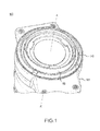
FIG. 1 illustrates a perspective view of an electro-mechanical actuator ("EMA"), in accordance with various embodiments; -
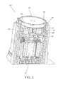
FIG. 2 illustrates a section view of an EMA including a magnetic disk park brake in an engaged position, in accordance with various embodiments; -
FIG. 3 illustrates a section view of an EMA including a magnetic disk park brake in a disengaged position, in accordance with various embodiments; -
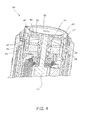
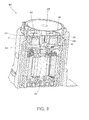
FIG. 4 illustrates a section view of an EMA including a bobbin insert in an engaged position, in accordance with various embodiments; -
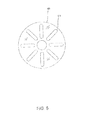
FIG. 5 illustrates a park brake disk, in accordance with various embodiments; and -
FIG. 6 illustrates a section view of an EMA including a bobbin insert in a disengaged position, in accordance with various embodiments. - The detailed description of exemplary embodiments herein makes reference to the accompanying drawings, which show various embodiments by way of illustration. While these various embodiments are described in sufficient detail to enable those skilled in the art to practice the disclosure, it should be understood that other embodiments may be realized and that logical changes and adaptations in design and construction may be made in accordance with this disclosure and the teachings herein. Thus, the detailed description herein is presented for purposes of illustration only and not of limitation. The scope of the disclosure is defined by the appended claims. For example, the steps recited in any of the method or process descriptions may be executed in any order and are not necessarily limited to the order presented. Furthermore, any reference to singular includes plural embodiments, and any reference to more than one component or step may include a singular embodiment or step. Also, any reference to attached, fixed, connected or the like may include permanent, removable, temporary, partial, full and/or any other possible attachment option. Additionally, any reference to without contact (or similar phrases) may also include reduced contact or minimal contact.
- In various embodiments, an aircraft brake system may comprise a brake system controller ("BSC") coupled to one or more electro-mechanical actuator controllers ("EMACs"), which may drive an electro-mechanical actuator ("EMA"). The BSC may be in communication with a brake pedal, and thus may control the EMACs in accordance with pilot/copilot braking commands. For example, brake pedal deflection may be indicative of pilot/copilot braking commands. The EMA may be coupled to or otherwise operate a pressure generating device, such as, for example, a ball screw, a ram, and/or the like. In operation, the EMA may cause the pressure generating device to move and/or exert a force on other brake system structures, such as a brake disk or pad to exert a force that restrains rotation of a wheel or other suitable moving structure. This stopping force may load and/or exert a corresponding force on the EMA structures such as, for example, an EMA housing.
- Referring to
FIG. 1 , a perspective view of an EMA 100 is shown. The EMA may extend along the axis marked A-A', with A being located near a distal portion of EMA 100 and A' being near a proximal portion of EMA 100. The EMA 100 may, as described above, be involved in the application of a braking force to an aircraft wheel. The EMA 100 assembly may comprise an EMAhousing 101, which may extend along the axis A-A'. The EMAhousing 101 may house a variety of components, including, for example, aball nut 140, aball screw 160, and a motor drive unit. Generally, the motor drive unit may drive the ball screw 160 through a plurality of rotations. As theball screw 160 rotates, theball nut 140 may translate distally and/or proximally along the axis A-A' (depending upon the direction of rotation of the ball screw 160). Theball nut 140 may be coupled to a disc or "puck," at a distal end thereof. The puck may exert a pressure against a brake stack coupled to an aircraft wheel to impede or halt a rolling motion of the wheel. The EMA may include a bi-stable park brake. For example, the EMA may comprise a park brake system (as described below with reference toFIGs. 2-6 ). - A brake may be used to prevent an EMA from rotating the ball screw in a first state, while permitting rotation of the ball screw in a second state. Prevention of ball screw rotation may be advantageous in a parking brake mode. A bi-stable brake may be switched from one state to another. After reaching either state, the state may be maintained without any additional energy input.
- Referring to
FIG. 2 , a section view of an EMA 200 with a magnetic disk park brake is illustrated according to various embodiments. EMA 200 may comprise amotor shaft 210. Themotor shaft 210 may rotate the ball screw in the actuator to transform the rotary motion of the ball screw into linear motion of the ball nut. Apark brake disk 220 may be coupled to themotor shaft 210. Thepark brake disk 220 may be magnetic. Thepark brake disk 220 may be manufactured to comprise minimal mass to avoid increased rotational inertia, and may be constructed with over molded plastic or other suitable low mass materials while containing a metal ring (e.g., a steel ring) to engage an engagement feature. - The EMA 200 may comprise a
voice coil assembly 230. Thevoice coil assembly 230 may comprise abobbin 231, abobbin magnet 232, awasher 233, avoice coil magnet 234, acopper wire 235, aplain bearing 236, areturn spring 237, and alinear guide 238. Thevoice coil magnet 234 may be a disk surrounding themotor shaft 210. Thewasher 233 may be axially adjacent to thevoice coil magnet 234 and surrounding themotor shaft 210. In various embodiments, thewasher 233 may comprise steel and/or another ferromagnetic material. Thevoice coil magnet 234 may magnetize thewasher 233. - The
bobbin 231 may comprise aninner cylinder 241 located between themotor shaft 210 and thevoice coil magnet 234. Thebobbin 231 may comprise anouter cylinder 242 located between thevoice coil magnet 234 and thelinear guide 238.Bobbin 231 may further comprise abobbin disk 243 extending between theinner cylinder 241 and theouter cylinder 242. Thebobbin 231 may be configured to translate axially alongmotor shaft 210.Copper wire 235 may be wound around theouter cylinder 242. In response to a voltage being applied to thecopper wire 235, a magnetic force may be applied to thecopper wire 235 from thevoice coil magnet 234 and thewasher 233, causing thebobbin 231 to translate axially either toward or away from thewasher 233, depending on the polarity of the voltage. - The
bobbin magnet 232 may be coupled to thebobbin disk 243. Thebobbin magnet 232 may be an engagement feature configured to contact thepark brake disk 220. Thebobbin magnet 232 may comprise a disk. As illustrated inFIG. 2 , theEMA 200 is in the engaged position, in which thebobbin magnet 232 is magnetically coupled to thepark brake disk 220. Friction between thebobbin magnet 232 and thepark brake disk 220 may preventpark brake disk 220 andmotor shaft 210 from rotating. Thus,EMA 200 may be in a locked position and may prevent the wheels of an aircraft from rotating. - A voltage may be applied to the
copper wire 235 in order to disengage the park brake. In response to the voltage being applied tocopper wire 235, a magnetic force between thecopper wire 235 and thevoice coil magnet 234 and thewasher 233 may drive thebobbin 231 toward thewasher 233. The force between thecopper wire 235 and thevoice coil magnet 234 and thewasher 233 may be greater than the force between thebobbin magnet 232 and thepark brake disk 220. This may separate thebobbin magnet 232 from thepark brake disk 220 and cause thebobbin 231 to translate toward thewasher 233 until thebobbin disk 243 contacts thewasher 233, as shown inFIG. 3 . Thelinear guide 238 may comprise anti-rotation guides which prevent thebobbin 231 from rotating. - Referring to
FIG. 3 , theEMA 200 is illustrated with the park brake in a disengaged position. Thebobbin magnet 232 is axially separated frompark brake disk 220. Thus,park brake disk 220 andmotor shaft 210 may rotate, which may allow the aircraft wheels to rotate. Thebobbin disk 243 may contact thewasher 233, and thereturn spring 237 may be compressed. A magnetic force between thebobbin magnet 232 and thewasher 233 andvoice coil magnet 234 may be stronger than a force on thebobbin 231 from thereturn spring 237. Thus, the disengaged position may be a stable state, in which no additional energy is required to maintain theEMA 200 in the disengaged position. - In order to engage the parking brake, a voltage may be applied to the
copper wire 235. The voltage to engage the parking brake may be opposite in polarity of the voltage to disengage the parking brake. The voltage may create a magnetic force between thecopper wire 235 and thewasher 233 and thevoice coil magnet 234. The magnetic force from thecopper wire 235 may be stronger than the magnetic force between thebobbin magnet 232 and thewasher 233 andvoice coil magnet 234. This may force thebobbin 231 to move within thelinear guide 238 away from thewasher 233 and toward thepark brake disk 220 to the engaged position shown inFIG. 1 . Thereturn spring 237 may bias thebobbin 231 toward thepark brake disk 220. Thus, thereturn spring 237 may provide additional force to drive thebobbin 231 toward thepark brake disk 220. Once in the engaged position, the voltage may be eliminated, and the park brake may be in a stable state in the engaged position. - Referring to
FIG. 4 , anEMA 400 comprising a park brake with abobbin insert 432 is illustrated in an engaged position according to various embodiments. TheEMA 400 may be similar to theEMA 200 illustrated inFIGs. 2 and3 . However,EMA 400 may comprise abobbin insert 432 in place of thebobbin magnet 232 ofEMA 200. Thebobbin insert 432 may comprise aninsert disk 451 located between theinner cylinder 241 and theouter cylinder 242 of thebobbin 231 and adjacent to thebobbin disk 243. Thebobbin insert 432 may further comprise one or more pins 452. Thepins 452 may extend through apertures inbobbin disk 243. In the engaged position,return spring 237 may maintain a pressure onbobbin 231 which contacts parkbrake disk 420. Friction between thepins 452 and thepark brake disk 420 may preventpark brake disk 420 andmotor shaft 210 from rotating. - Referring to
FIG. 5 , apark brake disk 420 is illustrated according to various embodiments. Thepark brake disk 420 may comprisegrooves 510. Thepins 452 shown inFIG. 4 may be inserted into thegrooves 510 to prevent thepark brake disk 420 from rotating. In the event that thepins 452 initially contact thepark brake disk 420 between thegrooves 510, thepark brake disk 420 may rotate until thepins 452 enter thegrooves 510. - Referring back to
FIG. 4 , a voltage may be applied to thecopper wire 235 in order to disengage the park brake. In response to the voltage being applied to thecopper wire 235, a magnetic force between thecopper wire 235 and thevoice coil magnet 234 and thewasher 233 may cause thebobbin 231 to move within thelinear guide 238 toward thewasher 233. The force between thecopper wire 235 and thevoice coil magnet 234 and thewasher 233 may be greater than the force from thereturn spring 237. This may separate thepins 452 from thepark brake disk 220 and cause thebobbin 231 to translate toward thewasher 233 until theinsert disk 451 contacts thewasher 233, as shown inFIG. 6 . - Referring to
FIG. 6 , theEMA 400 is illustrated with the park brake in a disengaged position. Thepins 452 are separated frompark brake disk 420. Thus,park brake disk 420 andmotor shaft 210 may rotate, which may allow the aircraft wheels to rotate. Theinsert disk 451 may contact thewasher 233, and thereturn spring 237 may be compressed. A magnetic force between theinsert disk 451 and thewasher 233 andvoice coil magnet 234 may be stronger than a force on thebobbin 231 from thereturn spring 237. Thus, the disengaged position may be a stable state, in which no additional energy is required to maintain theEMA 400 in the disengaged position. - In order to engage the parking brake, a voltage may be applied to the
copper wire 235. The voltage to engage the parking brake may be opposite in polarity of the voltage to disengage the parking brake. The voltage may create a magnetic force between thecopper wire 235 and thewasher 233 and thevoice coil magnet 234, The magnetic force from thecopper wire 235 may be stronger than the magnetic force between theinsert disk 451 and thewasher 233 andvoice coil magnet 234. This may cause thebobbin 231 to move within thelinear guide 238 away from thewasher 233 and toward thepark brake disk 220 to the engaged position shown inFIG. 4 . Thereturn spring 237 may provide additional force to drive thebobbin 231 toward thepark brake disk 220. Once in the engaged position, the voltage may be eliminated, and the park brake may be in a stable state in the engaged position. - Benefits, other advantages, and solutions to problems have been described herein with regard to specific embodiments. Furthermore, the connecting lines shown in the various figures contained herein are intended to represent exemplary functional relationships and/or physical couplings between the various elements. It should be noted that many alternative or additional functional relationships or physical connections may be present in a practical system. However, the benefits, advantages, solutions to problems, and any elements that may cause any benefit, advantage, or solution to occur or become more pronounced are not to be construed as critical, required, or essential features or elements of the disclosure. The scope of the disclosure is accordingly to be limited by nothing other than the appended claims, in which reference to an element in the singular is not intended to mean "one and only one" unless explicitly so stated, but rather "one or more." Moreover, where a phrase similar to "at least one of A, B, or C" is used in the claims, it is intended that the phrase be interpreted to mean that A alone may be present in an embodiment, B alone may be present in an embodiment, C alone may be present in an embodiment, or that any combination of the elements A, B and C may be present in a single embodiment; for example, A and B, A and C, B and C, or A and B and C.
- Systems, methods and apparatus are provided herein. In the detailed description herein, references to "various embodiments", "one embodiment", "an embodiment", "an example embodiment", etc., indicate that the embodiment described may include a particular feature, structure, or characteristic, but every embodiment may not necessarily include the particular feature, structure, or characteristic. Moreover, such phrases are not necessarily referring to the same embodiment. Further, when a particular feature, structure, or characteristic is described in connection with an embodiment, it is submitted that it is within the knowledge of one skilled in the art to affect such feature, structure, or characteristic in connection with other embodiments whether or not explicitly described. After reading the description, it will be apparent to one skilled in the relevant art(s) how to implement the disclosure in alternative embodiments.
- Furthermore, no element, component, or method step in the present disclosure is intended to be dedicated to the public regardless of whether the element, component, or method step is explicitly recited in the claims. As used herein, the terms "comprises", "comprising", or any other variation thereof, are intended to cover a non-exclusive inclusion, such that a process, method, article, or apparatus that comprises a list of elements does not include only those elements but may include other elements not expressly listed or inherent to such process, method, article, or apparatus.
Claims (15)
- An electro-mechanical actuator ("EMA") (200) comprising:a motor shaft (210);a park brake disk (220) coupled to the motor shaft (210); anda voice coil assembly (230), the voice coil assembly comprising an engagement feature configured to contact the park brake disk (220).
- The EMA (200) of claim 1, wherein the voice coil assembly (230) comprises a bobbin (231) configured to translate along the motor shaft (220) and a wire (235) wound around the bobbin.
- The EMA (200) of claim 2, wherein the engagement feature comprises a bobbin magnet (232).
- The EMA (200) of claim 3, wherein the bobbin magnet (232) comprises a magnetic disk coupled to the bobbin (231).
- The EMA (200) of claim 1, wherein the engagement feature comprises a bobbin insert (432) coupled to a bobbin (231).
- The EMA (200) of claim 5, wherein the bobbin insert (432) comprises an insert disk (451) and a pin (452) extending through an aperture in the bobbin.
- The EMA (200) of claim 2, further comprising a return spring (237) configured to bias the bobbin (231) toward the park brake disk (220).
- The EMA (200) of claim 1, wherein the voice coil assembly (230) comprises an anti-rotation feature.
- A system for locking an aircraft brake comprising:a motor shaft (210);a park brake disk (220) coupled to the motor shaft (210);a voice coil magnet (234) located around the motor shaft (210);a steel washer (233) located around the motor shaft (210) and adjacent to the voice coil magnet (234);a bobbin (231) comprising an inner cylinder (241), an outer cylinder (242), and a bobbin disk (243); andan engagement feature coupled to the bobbin disk (243);wherein the bobbin (231) is translatable along the motor shaft (210) between an engaged position and a disengaged position.
- The system of claim 9, wherein, in the engaged position, the engagement feature is in contact with the park brake disk (220), and wherein, in the disengaged position, the engagement feature is magnetically coupled to the steel washer (233).
- The system of claim 9, wherein the engagement feature comprises a bobbin magnet (232).
- The system of claim 9, wherein the engagement feature comprises a bobbin insert (432) comprising an insert disk (452) and a pin (452).
- The system of claim 9, wherein the park brake disk (220) comprises a groove.
- The system of claim 9, further comprising a copper wire (233) wound around the outer cylinder.
- The system of claim 14, wherein the bobbin (231) is configured to translate in response to a voltage applied to the copper wire (233).
Applications Claiming Priority (1)
| Application Number | Priority Date | Filing Date | Title |
|---|---|---|---|
| US14/454,377 US9359069B2 (en) | 2014-08-07 | 2014-08-07 | Apparatus and system for aircraft park brake systems |
Publications (2)
| Publication Number | Publication Date |
|---|---|
| EP2982557A1 true EP2982557A1 (en) | 2016-02-10 |
| EP2982557B1 EP2982557B1 (en) | 2018-10-03 |
Family
ID=53776445
Family Applications (1)
| Application Number | Title | Priority Date | Filing Date |
|---|---|---|---|
| EP15179529.1A Active EP2982557B1 (en) | 2014-08-07 | 2015-08-03 | Apparatus and system for aircraft park brake systems |
Country Status (2)
| Country | Link |
|---|---|
| US (1) | US9359069B2 (en) |
| EP (1) | EP2982557B1 (en) |
Cited By (1)
| Publication number | Priority date | Publication date | Assignee | Title |
|---|---|---|---|---|
| CN108749795A (en) * | 2018-07-17 | 2018-11-06 | 浙江零跑科技有限公司 | A kind of used in new energy vehicles parking device |
Families Citing this family (3)
| Publication number | Priority date | Publication date | Assignee | Title |
|---|---|---|---|---|
| US10518761B2 (en) | 2016-07-01 | 2019-12-31 | Akebono Brake Industry Co., Ltd | Electric park brake with electromagnetic brake |
| US9994425B1 (en) * | 2016-12-12 | 2018-06-12 | Thyssenkrupp Elevator Ag | Compact motor arrangement with integrated brakes and shaft bearings |
| US10106139B2 (en) | 2017-02-02 | 2018-10-23 | Goodrich Corporation | Brake systems and methods |
Citations (5)
| Publication number | Priority date | Publication date | Assignee | Title |
|---|---|---|---|---|
| US20050109568A1 (en) * | 2003-11-25 | 2005-05-26 | Russ Ether | Electric park brake mechanism and method of operating an electric brake to perform a park brake function |
| EP1679242A1 (en) * | 2005-01-11 | 2006-07-12 | Messier-Bugatti | Protection procedure in a braking system of a vehicle with electric brakes |
| US20100210391A1 (en) * | 2009-02-13 | 2010-08-19 | Garmin International, Inc. | Planetary drive servo actuator |
| EP2466164A2 (en) * | 2010-12-15 | 2012-06-20 | Honeywell International, Inc. | Electromechanical brake actuator motor brake |
| FR2975151A1 (en) * | 2011-05-12 | 2012-11-16 | Liebherr Aerospace Gmbh | BI-DIRECTIONAL ROTATION LOCKING OR LOCKING DEVICE |
Family Cites Families (4)
| Publication number | Priority date | Publication date | Assignee | Title |
|---|---|---|---|---|
| US5185542A (en) | 1991-08-28 | 1993-02-09 | Electroid Company | Electromagnetic pulse operated bi-stable brake |
| DE19851196A1 (en) * | 1998-11-06 | 2000-05-25 | Harting Kgaa | Electromagnetically actuated brake, especially holding brake, has ferromagnetic, twist-proof cam plate with cams engaging in openings in rotatable part to be braked in shape-locking manner |
| US7063190B1 (en) * | 2003-09-09 | 2006-06-20 | Mpc Products Corporation | Braking system |
| US7347305B2 (en) * | 2003-10-16 | 2008-03-25 | Delphi Technologies, Inc. | Park brake system having a latching device |
-
2014
- 2014-08-07 US US14/454,377 patent/US9359069B2/en active Active
-
2015
- 2015-08-03 EP EP15179529.1A patent/EP2982557B1/en active Active
Patent Citations (5)
| Publication number | Priority date | Publication date | Assignee | Title |
|---|---|---|---|---|
| US20050109568A1 (en) * | 2003-11-25 | 2005-05-26 | Russ Ether | Electric park brake mechanism and method of operating an electric brake to perform a park brake function |
| EP1679242A1 (en) * | 2005-01-11 | 2006-07-12 | Messier-Bugatti | Protection procedure in a braking system of a vehicle with electric brakes |
| US20100210391A1 (en) * | 2009-02-13 | 2010-08-19 | Garmin International, Inc. | Planetary drive servo actuator |
| EP2466164A2 (en) * | 2010-12-15 | 2012-06-20 | Honeywell International, Inc. | Electromechanical brake actuator motor brake |
| FR2975151A1 (en) * | 2011-05-12 | 2012-11-16 | Liebherr Aerospace Gmbh | BI-DIRECTIONAL ROTATION LOCKING OR LOCKING DEVICE |
Cited By (1)
| Publication number | Priority date | Publication date | Assignee | Title |
|---|---|---|---|---|
| CN108749795A (en) * | 2018-07-17 | 2018-11-06 | 浙江零跑科技有限公司 | A kind of used in new energy vehicles parking device |
Also Published As
| Publication number | Publication date |
|---|---|
| EP2982557B1 (en) | 2018-10-03 |
| US9359069B2 (en) | 2016-06-07 |
| US20160039520A1 (en) | 2016-02-11 |
Similar Documents
| Publication | Publication Date | Title |
|---|---|---|
| EP2982557B1 (en) | Apparatus and system for aircraft park brake systems | |
| EP3115645B1 (en) | Dual-rate linear actuator | |
| US5121018A (en) | Latching brake using permanent magnet | |
| EP2930392A2 (en) | Park brake system and electric motor actuator. | |
| US8058757B2 (en) | Electric motor with passive integral brake | |
| EP3263414A1 (en) | Electric park brake with electromagnetic brake | |
| EP2930504A2 (en) | State sensor system and methods | |
| EP3045361B1 (en) | Bi-stable voice coil park brake | |
| US9308990B2 (en) | Voice coil linear activated park brake | |
| EP2837534A1 (en) | Internal park brake system | |
| US20180106315A1 (en) | Parking brake torque locking mechanism | |
| KR102552472B1 (en) | Brake assembly and method for controlling the brake assembly | |
| EP3042812B1 (en) | Bi-stable brake with permanent magnet array | |
| US12038098B2 (en) | Manually controlled electromagnetic actuator and parking brake valve provided with such an actuator | |
| KR20170089327A (en) | Actuator Unit Of Electronic Parking Brake | |
| WO2003098067A1 (en) | Electromagnetically lifted friction brake comprising a collet chuck for simultaneously braking a drive part in the peripheral and axial direction | |
| CN216241931U (en) | Brake for power-off | |
| US20230420169A1 (en) | Bistable electromagnetic actuator and aircraft brake valve provided with such an actuator | |
| CN220904941U (en) | Pedal brake device and vehicle | |
| DE19946084A1 (en) | Electromechanical drive unit e.g. for vehicle braking system, has brake engagement magnet arrangement with permanent magnet and electromagnet that influences magnetic field generated by permanent magnet | |
| EP4556326A1 (en) | Control for an electromechanical brake actuator | |
| CN108736690B (en) | Excitation device and excitation-free working brake | |
| WO2026027134A1 (en) | Spring-return actuator comprising a dc motor having a detent-torque restraint for latching and releasing an actuating element of the actuator into and out of an actuating position | |
| HK1154999A (en) | Electric motor with passive integral brake |
Legal Events
| Date | Code | Title | Description |
|---|---|---|---|
| PUAI | Public reference made under article 153(3) epc to a published international application that has entered the european phase |
Free format text: ORIGINAL CODE: 0009012 |
|
| AK | Designated contracting states |
Kind code of ref document: A1 Designated state(s): AL AT BE BG CH CY CZ DE DK EE ES FI FR GB GR HR HU IE IS IT LI LT LU LV MC MK MT NL NO PL PT RO RS SE SI SK SM TR |
|
| AX | Request for extension of the european patent |
Extension state: BA ME |
|
| 17P | Request for examination filed |
Effective date: 20160809 |
|
| RBV | Designated contracting states (corrected) |
Designated state(s): AL AT BE BG CH CY CZ DE DK EE ES FI FR GB GR HR HU IE IS IT LI LT LU LV MC MK MT NL NO PL PT RO RS SE SI SK SM TR |
|
| GRAP | Despatch of communication of intention to grant a patent |
Free format text: ORIGINAL CODE: EPIDOSNIGR1 |
|
| STAA | Information on the status of an ep patent application or granted ep patent |
Free format text: STATUS: GRANT OF PATENT IS INTENDED |
|
| INTG | Intention to grant announced |
Effective date: 20180222 |
|
| GRAS | Grant fee paid |
Free format text: ORIGINAL CODE: EPIDOSNIGR3 |
|
| GRAJ | Information related to disapproval of communication of intention to grant by the applicant or resumption of examination proceedings by the epo deleted |
Free format text: ORIGINAL CODE: EPIDOSDIGR1 |
|
| GRAL | Information related to payment of fee for publishing/printing deleted |
Free format text: ORIGINAL CODE: EPIDOSDIGR3 |
|
| STAA | Information on the status of an ep patent application or granted ep patent |
Free format text: STATUS: REQUEST FOR EXAMINATION WAS MADE |
|
| GRAR | Information related to intention to grant a patent recorded |
Free format text: ORIGINAL CODE: EPIDOSNIGR71 |
|
| STAA | Information on the status of an ep patent application or granted ep patent |
Free format text: STATUS: GRANT OF PATENT IS INTENDED |
|
| INTC | Intention to grant announced (deleted) | ||
| GRAA | (expected) grant |
Free format text: ORIGINAL CODE: 0009210 |
|
| STAA | Information on the status of an ep patent application or granted ep patent |
Free format text: STATUS: THE PATENT HAS BEEN GRANTED |
|
| INTG | Intention to grant announced |
Effective date: 20180814 |
|
| AK | Designated contracting states |
Kind code of ref document: B1 Designated state(s): AL AT BE BG CH CY CZ DE DK EE ES FI FR GB GR HR HU IE IS IT LI LT LU LV MC MK MT NL NO PL PT RO RS SE SI SK SM TR |
|
| REG | Reference to a national code |
Ref country code: GB Ref legal event code: FG4D |
|
| REG | Reference to a national code |
Ref country code: CH Ref legal event code: EP Ref country code: AT Ref legal event code: REF Ref document number: 1048260 Country of ref document: AT Kind code of ref document: T Effective date: 20181015 |
|
| REG | Reference to a national code |
Ref country code: IE Ref legal event code: FG4D Ref country code: DE Ref legal event code: R096 Ref document number: 602015017376 Country of ref document: DE |
|
| REG | Reference to a national code |
Ref country code: NL Ref legal event code: MP Effective date: 20181003 |
|
| REG | Reference to a national code |
Ref country code: LT Ref legal event code: MG4D |
|
| REG | Reference to a national code |
Ref country code: AT Ref legal event code: MK05 Ref document number: 1048260 Country of ref document: AT Kind code of ref document: T Effective date: 20181003 |
|
| PG25 | Lapsed in a contracting state [announced via postgrant information from national office to epo] |
Ref country code: NL Free format text: LAPSE BECAUSE OF FAILURE TO SUBMIT A TRANSLATION OF THE DESCRIPTION OR TO PAY THE FEE WITHIN THE PRESCRIBED TIME-LIMIT Effective date: 20181003 |
|
| PG25 | Lapsed in a contracting state [announced via postgrant information from national office to epo] |
Ref country code: FI Free format text: LAPSE BECAUSE OF FAILURE TO SUBMIT A TRANSLATION OF THE DESCRIPTION OR TO PAY THE FEE WITHIN THE PRESCRIBED TIME-LIMIT Effective date: 20181003 Ref country code: NO Free format text: LAPSE BECAUSE OF FAILURE TO SUBMIT A TRANSLATION OF THE DESCRIPTION OR TO PAY THE FEE WITHIN THE PRESCRIBED TIME-LIMIT Effective date: 20190103 Ref country code: IS Free format text: LAPSE BECAUSE OF FAILURE TO SUBMIT A TRANSLATION OF THE DESCRIPTION OR TO PAY THE FEE WITHIN THE PRESCRIBED TIME-LIMIT Effective date: 20190203 Ref country code: AT Free format text: LAPSE BECAUSE OF FAILURE TO SUBMIT A TRANSLATION OF THE DESCRIPTION OR TO PAY THE FEE WITHIN THE PRESCRIBED TIME-LIMIT Effective date: 20181003 Ref country code: ES Free format text: LAPSE BECAUSE OF FAILURE TO SUBMIT A TRANSLATION OF THE DESCRIPTION OR TO PAY THE FEE WITHIN THE PRESCRIBED TIME-LIMIT Effective date: 20181003 Ref country code: LV Free format text: LAPSE BECAUSE OF FAILURE TO SUBMIT A TRANSLATION OF THE DESCRIPTION OR TO PAY THE FEE WITHIN THE PRESCRIBED TIME-LIMIT Effective date: 20181003 Ref country code: CZ Free format text: LAPSE BECAUSE OF FAILURE TO SUBMIT A TRANSLATION OF THE DESCRIPTION OR TO PAY THE FEE WITHIN THE PRESCRIBED TIME-LIMIT Effective date: 20181003 Ref country code: HR Free format text: LAPSE BECAUSE OF FAILURE TO SUBMIT A TRANSLATION OF THE DESCRIPTION OR TO PAY THE FEE WITHIN THE PRESCRIBED TIME-LIMIT Effective date: 20181003 Ref country code: PL Free format text: LAPSE BECAUSE OF FAILURE TO SUBMIT A TRANSLATION OF THE DESCRIPTION OR TO PAY THE FEE WITHIN THE PRESCRIBED TIME-LIMIT Effective date: 20181003 Ref country code: LT Free format text: LAPSE BECAUSE OF FAILURE TO SUBMIT A TRANSLATION OF THE DESCRIPTION OR TO PAY THE FEE WITHIN THE PRESCRIBED TIME-LIMIT Effective date: 20181003 Ref country code: BG Free format text: LAPSE BECAUSE OF FAILURE TO SUBMIT A TRANSLATION OF THE DESCRIPTION OR TO PAY THE FEE WITHIN THE PRESCRIBED TIME-LIMIT Effective date: 20190103 |
|
| PG25 | Lapsed in a contracting state [announced via postgrant information from national office to epo] |
Ref country code: PT Free format text: LAPSE BECAUSE OF FAILURE TO SUBMIT A TRANSLATION OF THE DESCRIPTION OR TO PAY THE FEE WITHIN THE PRESCRIBED TIME-LIMIT Effective date: 20190203 Ref country code: GR Free format text: LAPSE BECAUSE OF FAILURE TO SUBMIT A TRANSLATION OF THE DESCRIPTION OR TO PAY THE FEE WITHIN THE PRESCRIBED TIME-LIMIT Effective date: 20190104 Ref country code: SE Free format text: LAPSE BECAUSE OF FAILURE TO SUBMIT A TRANSLATION OF THE DESCRIPTION OR TO PAY THE FEE WITHIN THE PRESCRIBED TIME-LIMIT Effective date: 20181003 Ref country code: AL Free format text: LAPSE BECAUSE OF FAILURE TO SUBMIT A TRANSLATION OF THE DESCRIPTION OR TO PAY THE FEE WITHIN THE PRESCRIBED TIME-LIMIT Effective date: 20181003 Ref country code: RS Free format text: LAPSE BECAUSE OF FAILURE TO SUBMIT A TRANSLATION OF THE DESCRIPTION OR TO PAY THE FEE WITHIN THE PRESCRIBED TIME-LIMIT Effective date: 20181003 |
|
| REG | Reference to a national code |
Ref country code: DE Ref legal event code: R097 Ref document number: 602015017376 Country of ref document: DE |
|
| PG25 | Lapsed in a contracting state [announced via postgrant information from national office to epo] |
Ref country code: IT Free format text: LAPSE BECAUSE OF FAILURE TO SUBMIT A TRANSLATION OF THE DESCRIPTION OR TO PAY THE FEE WITHIN THE PRESCRIBED TIME-LIMIT Effective date: 20181003 Ref country code: DK Free format text: LAPSE BECAUSE OF FAILURE TO SUBMIT A TRANSLATION OF THE DESCRIPTION OR TO PAY THE FEE WITHIN THE PRESCRIBED TIME-LIMIT Effective date: 20181003 |
|
| PLBE | No opposition filed within time limit |
Free format text: ORIGINAL CODE: 0009261 |
|
| STAA | Information on the status of an ep patent application or granted ep patent |
Free format text: STATUS: NO OPPOSITION FILED WITHIN TIME LIMIT |
|
| PG25 | Lapsed in a contracting state [announced via postgrant information from national office to epo] |
Ref country code: EE Free format text: LAPSE BECAUSE OF FAILURE TO SUBMIT A TRANSLATION OF THE DESCRIPTION OR TO PAY THE FEE WITHIN THE PRESCRIBED TIME-LIMIT Effective date: 20181003 Ref country code: SM Free format text: LAPSE BECAUSE OF FAILURE TO SUBMIT A TRANSLATION OF THE DESCRIPTION OR TO PAY THE FEE WITHIN THE PRESCRIBED TIME-LIMIT Effective date: 20181003 Ref country code: SK Free format text: LAPSE BECAUSE OF FAILURE TO SUBMIT A TRANSLATION OF THE DESCRIPTION OR TO PAY THE FEE WITHIN THE PRESCRIBED TIME-LIMIT Effective date: 20181003 Ref country code: RO Free format text: LAPSE BECAUSE OF FAILURE TO SUBMIT A TRANSLATION OF THE DESCRIPTION OR TO PAY THE FEE WITHIN THE PRESCRIBED TIME-LIMIT Effective date: 20181003 |
|
| 26N | No opposition filed |
Effective date: 20190704 |
|
| PG25 | Lapsed in a contracting state [announced via postgrant information from national office to epo] |
Ref country code: SI Free format text: LAPSE BECAUSE OF FAILURE TO SUBMIT A TRANSLATION OF THE DESCRIPTION OR TO PAY THE FEE WITHIN THE PRESCRIBED TIME-LIMIT Effective date: 20181003 |
|
| REG | Reference to a national code |
Ref country code: DE Ref legal event code: R119 Ref document number: 602015017376 Country of ref document: DE |
|
| PG25 | Lapsed in a contracting state [announced via postgrant information from national office to epo] |
Ref country code: TR Free format text: LAPSE BECAUSE OF FAILURE TO SUBMIT A TRANSLATION OF THE DESCRIPTION OR TO PAY THE FEE WITHIN THE PRESCRIBED TIME-LIMIT Effective date: 20181003 |
|
| PG25 | Lapsed in a contracting state [announced via postgrant information from national office to epo] |
Ref country code: LU Free format text: LAPSE BECAUSE OF NON-PAYMENT OF DUE FEES Effective date: 20190803 Ref country code: LI Free format text: LAPSE BECAUSE OF NON-PAYMENT OF DUE FEES Effective date: 20190831 Ref country code: CH Free format text: LAPSE BECAUSE OF NON-PAYMENT OF DUE FEES Effective date: 20190831 Ref country code: MC Free format text: LAPSE BECAUSE OF FAILURE TO SUBMIT A TRANSLATION OF THE DESCRIPTION OR TO PAY THE FEE WITHIN THE PRESCRIBED TIME-LIMIT Effective date: 20181003 |
|
| REG | Reference to a national code |
Ref country code: BE Ref legal event code: MM Effective date: 20190831 |
|
| PG25 | Lapsed in a contracting state [announced via postgrant information from national office to epo] |
Ref country code: DE Free format text: LAPSE BECAUSE OF NON-PAYMENT OF DUE FEES Effective date: 20200303 Ref country code: IE Free format text: LAPSE BECAUSE OF NON-PAYMENT OF DUE FEES Effective date: 20190803 |
|
| PG25 | Lapsed in a contracting state [announced via postgrant information from national office to epo] |
Ref country code: BE Free format text: LAPSE BECAUSE OF NON-PAYMENT OF DUE FEES Effective date: 20190831 |
|
| PG25 | Lapsed in a contracting state [announced via postgrant information from national office to epo] |
Ref country code: CY Free format text: LAPSE BECAUSE OF FAILURE TO SUBMIT A TRANSLATION OF THE DESCRIPTION OR TO PAY THE FEE WITHIN THE PRESCRIBED TIME-LIMIT Effective date: 20181003 |
|
| PG25 | Lapsed in a contracting state [announced via postgrant information from national office to epo] |
Ref country code: HU Free format text: LAPSE BECAUSE OF FAILURE TO SUBMIT A TRANSLATION OF THE DESCRIPTION OR TO PAY THE FEE WITHIN THE PRESCRIBED TIME-LIMIT; INVALID AB INITIO Effective date: 20150803 Ref country code: MT Free format text: LAPSE BECAUSE OF FAILURE TO SUBMIT A TRANSLATION OF THE DESCRIPTION OR TO PAY THE FEE WITHIN THE PRESCRIBED TIME-LIMIT Effective date: 20181003 |
|
| PG25 | Lapsed in a contracting state [announced via postgrant information from national office to epo] |
Ref country code: MK Free format text: LAPSE BECAUSE OF FAILURE TO SUBMIT A TRANSLATION OF THE DESCRIPTION OR TO PAY THE FEE WITHIN THE PRESCRIBED TIME-LIMIT Effective date: 20181003 |
|
| P01 | Opt-out of the competence of the unified patent court (upc) registered |
Effective date: 20230522 |
|
| PGFP | Annual fee paid to national office [announced via postgrant information from national office to epo] |
Ref country code: GB Payment date: 20250725 Year of fee payment: 11 |
|
| PGFP | Annual fee paid to national office [announced via postgrant information from national office to epo] |
Ref country code: FR Payment date: 20250723 Year of fee payment: 11 |