EP2982410A2 - Defibrillator and method of controlling defibrillator - Google Patents
Defibrillator and method of controlling defibrillator Download PDFInfo
- Publication number
- EP2982410A2 EP2982410A2 EP15178585.4A EP15178585A EP2982410A2 EP 2982410 A2 EP2982410 A2 EP 2982410A2 EP 15178585 A EP15178585 A EP 15178585A EP 2982410 A2 EP2982410 A2 EP 2982410A2
- Authority
- EP
- European Patent Office
- Prior art keywords
- measurement value
- impedance measurement
- defibrillator
- electrodes
- impedance
- Prior art date
- Legal status (The legal status is an assumption and is not a legal conclusion. Google has not performed a legal analysis and makes no representation as to the accuracy of the status listed.)
- Granted
Links
Images




Classifications
-
- A—HUMAN NECESSITIES
- A61—MEDICAL OR VETERINARY SCIENCE; HYGIENE
- A61N—ELECTROTHERAPY; MAGNETOTHERAPY; RADIATION THERAPY; ULTRASOUND THERAPY
- A61N1/00—Electrotherapy; Circuits therefor
- A61N1/18—Applying electric currents by contact electrodes
- A61N1/32—Applying electric currents by contact electrodes alternating or intermittent currents
- A61N1/38—Applying electric currents by contact electrodes alternating or intermittent currents for producing shock effects
- A61N1/39—Heart defibrillators
- A61N1/3925—Monitoring; Protecting
-
- A—HUMAN NECESSITIES
- A61—MEDICAL OR VETERINARY SCIENCE; HYGIENE
- A61N—ELECTROTHERAPY; MAGNETOTHERAPY; RADIATION THERAPY; ULTRASOUND THERAPY
- A61N1/00—Electrotherapy; Circuits therefor
- A61N1/02—Details
- A61N1/04—Electrodes
- A61N1/0404—Electrodes for external use
- A61N1/0408—Use-related aspects
- A61N1/046—Specially adapted for shock therapy, e.g. defibrillation
-
- A—HUMAN NECESSITIES
- A61—MEDICAL OR VETERINARY SCIENCE; HYGIENE
- A61N—ELECTROTHERAPY; MAGNETOTHERAPY; RADIATION THERAPY; ULTRASOUND THERAPY
- A61N1/00—Electrotherapy; Circuits therefor
- A61N1/18—Applying electric currents by contact electrodes
- A61N1/32—Applying electric currents by contact electrodes alternating or intermittent currents
- A61N1/36—Applying electric currents by contact electrodes alternating or intermittent currents for stimulation
- A61N1/362—Heart stimulators
- A61N1/3625—External stimulators
-
- A—HUMAN NECESSITIES
- A61—MEDICAL OR VETERINARY SCIENCE; HYGIENE
- A61N—ELECTROTHERAPY; MAGNETOTHERAPY; RADIATION THERAPY; ULTRASOUND THERAPY
- A61N1/00—Electrotherapy; Circuits therefor
- A61N1/18—Applying electric currents by contact electrodes
- A61N1/32—Applying electric currents by contact electrodes alternating or intermittent currents
- A61N1/38—Applying electric currents by contact electrodes alternating or intermittent currents for producing shock effects
- A61N1/39—Heart defibrillators
- A61N1/3904—External heart defibrillators [EHD]
-
- A—HUMAN NECESSITIES
- A61—MEDICAL OR VETERINARY SCIENCE; HYGIENE
- A61N—ELECTROTHERAPY; MAGNETOTHERAPY; RADIATION THERAPY; ULTRASOUND THERAPY
- A61N1/00—Electrotherapy; Circuits therefor
- A61N1/18—Applying electric currents by contact electrodes
- A61N1/32—Applying electric currents by contact electrodes alternating or intermittent currents
- A61N1/38—Applying electric currents by contact electrodes alternating or intermittent currents for producing shock effects
- A61N1/39—Heart defibrillators
- A61N1/3993—User interfaces for automatic external defibrillators
Definitions
- the presently disclosed subject matter relates to a defibrillator and a method of controlling a defibrillator.
- a defibrillator applies an electrical stimulus to arrhythmia such as ventricular fibrillation (VF) or ventricular tachycardia (VT) to perform defibrillation or cardioversion.
- a defibrillator which is used in a medical facility can be connected to external paddles, internal paddles, disposable pads, and the like which function as electrodes to be contacted with the body surface of the rescue target (patient).
- the user mainly, a doctor
- disposable pads are to be used as electrodes, it is important that the impedance between the disposable pads and the body surface of the rescue target is low.
- JP-A-2013-240466 discloses a defibrillator having means for testing the integrity of electrodes.
- the defibrillator checks measurement values of the electric resistance of the electrodes to determine whether the electrodes are in the normal state or not (see Paragraph 0024 of JP-A-2013-240466 ).
- a defibrillator which is used in a medical facility can use various kinds of electrodes (external paddles, internal paddles, and disposable pads).
- electrodes external paddles, internal paddles, and disposable pads.
- the impedance with the body surface is very useful information.
- consideration of such impedance is not important.
- the measured value is referred to as "impedance measurement value").
- the presently disclosed subject matter may provide a defibrillator which is easily operated in a state where a high treatment effect is achieved, and a method of controlling such a defibrillator.
- the defibrillator may comprise: an impedance measuring section which is configured to obtain an impedance measurement value between a living body of a rescue target and electrodes; a controller which is configured to detect a kind of the electrodes, and which, based on the detected kind of the electrodes, is configured to perform determination of whether the impedance measurement value is to be output or not; and an outputting section which, based on the determination, is configured to output the impedance measurement value.
- the defibrillator may comprise: an impedance measuring section which is configured to obtain an impedance measurement value between a living body of a rescue target and electrodes; a controller which is configured to detect an operation mode of the defibrillator, and which, based on the detected operation mode, is configured to perform determination of whether the impedance measurement value is to be output or not; and an outputting section which, based on the determination, is configured to output the impedance measurement value.
- Fig. 1 is a perspective view showing an example of the external configuration of a defibrillator 1 of the embodiment.
- the configuration of the defibrillator 1 shown in Fig. 1 is a mere example, and it is a matter of course that the defibrillator may have another shape.
- Fig. 1 shows a state where external paddles are attached to the defibrillator 1.
- the defibrillator 1 is used in, for example, a medical facility or an ambulance under operation by the user (mainly, a doctor).
- the user refers an electrocardiogram of the rescue target (patient). If it is determined that an electrical shock is necessary, the user performs a charging process, and then applies an electrical shock to the rescue target.
- Fig. 2 is a block diagram showing the internal configuration of the defibrillator of the embodiment.
- the defibrillator 1 has a power supplying section 2, a storage section 3, a communicating section 4, an operating section 5, a controller 6, a displaying section 7, a sound generating section 8, an electrocardiogram signal amplifier 9, a high-voltage generating section 10, a high-voltage capacitor 11, a connector 12, and an impedance measuring section 13.
- the defibrillator 1 is connected to electrodes 14 through the connector 12.
- the electrodes 14 include so-called external paddles (external electrodes), internal paddles (internal electrodes), and disposable pads (so-called adhesive disposable pads).
- the electrodes 14 are contacted with the body surface of the rescue target.
- disposable pads it is important that the impedance between the body surface of the rescue target and the disposable pads is in a low state. When the impedance is high, the effect of defibrillation (electrical shock) is not sufficient, and there is a possibility that the disposable pads may be disconnected during defibrillation.
- the defibrillator 1 operates in various operation modes. Examples of the operation modes are a monitor mode and a defibrillation mode.
- the monitor mode is an operation mode in which biological information of the rescue target is acquired and displayed on the displaying section 7 that will be described later.
- the defibrillation mode is an operation mode in which defibrillation is performed on the rescue target.
- the defibrillator 1 may be configured so as to operate also in a pacing mode.
- the pacing mode is an operation mode for regulating contractions of the right and left ventricles.
- the defibrillator 1 may be configured so as to have an SpO2 adaptor and a connection interface with a CO2 sensor.
- the defibrillator 1 may have an incorporated printer and the like.
- the power supplying section 2 is a battery which supplies electric power to the processing sections in the defibrillator 1.
- the power supplying section 2 performs voltage conversion by using a voltage controlling mechanism which is not shown, and supplies electric power to the processing sections.
- the storage section 3 stores programs which are necessary for enabling the defibrillator 1 to operate, audio data, adjustment values, measured electrocardiogram waveforms, and the like.
- the storage section 3 is a secondary storage device such as a hard disk drive.
- a part of the storage section 3 may be configured by a device which is attachable to and detachable from the defibrillator 1 (for example, a USB (Universal Serial Bus) memory).
- the communicating section 4 is a wireless interface which communicates with medical servers and the like on a network.
- the communicating section 4 transmits acquired electrocardiogram waveforms and the like to the medical servers and the like, as required. It is not always necessary for the defibrillator 1 to include the communicating section 4.
- the operating section 5 is an interface for enabling the user to operate the defibrillator 1.
- the operating section 5 is configured by knobs, buttons, and the like which are disposed on the surface of the case in order to designate the charged energy amount.
- the controller 6 controls various operations of the defibrillator 1. Specifically, the controller 6 performs various operation controls such as charging/discharging of energy, a sequence control, an electrocardiogram analysis, and a control of an audio output.
- the controller 6 is configured by a CPU (Central Processing Unit), a gate array, an A/D converter, etc.
- the controller 6 further performs a control of a display of an impedance measurement value on the displaying section 7, as described later.
- the displaying section 7 visually outputs the state of the defibrillator 1 and the like.
- the displaying section 7 is configured by a liquid crystal display device (TFT LCD screen) disposed on the surface of the case of the defibrillator 1, a control circuit for the device, etc.
- the sound generating section 8 audibly outputs (sound outputs) the state of the defibrillator 1 and the like.
- the displaying section 7 and the sound generating section 8 can be deemed as one mode of an outputting section which outputs the state of the defibrillator 1, the impedance measurement value of the electrodes 14 which will be described later, and the like.
- the electrocardiogram signal amplifier 9 performs filtering and an amplification process on an electrocardiogram signal obtained from the electrodes 14 which are connected to the connector 12.
- the high-voltage generating section 10 charges and discharges energy which is to be used in defibrillation, in accordance with the control of the controller 6. Energy for defibrillation is charge in the high-voltage capacitor 11.
- the connector 12 is a connection interface which is used in the connection with the electrodes 14 which are to be contacted to the body surface of the rescue target.
- the connector 12 has connector pins corresponding to the kinds of the electrodes 14.
- the electrodes 14 are connected to the corresponding ones of the connector pins.
- the electrodes 14 are external paddles (external electrodes), internal paddles (internal electrodes), disposable pads (so-called disposable adhesive pads), etc. During execution of defibrillation or pacing, the electrodes 14 are contacted with the body surface of the rescue target. The electrodes 14 are attached to the connector 12.
- the impedance measuring section 13 measures the impedance between the electrodes 14 and the body surface of the rescue target.
- the impedance measuring section 13 supplies the measurement value of the measured impedance (impedance measurement value) to the controller 6.
- the controller 6 detects the connection state of the connector 12 and the electrodes 14, particularly whether a state where disposable pads are connected to the connector is obtained or not. In the detecting process, for example, the determination is performed based on the connection states of the connector pins constituting the above-described connector 12. The controller 6 further determines the kind of the operation mode. Then, the controller 6 determines whether the impedance measurement value is to be displayed on the displaying section 7 or not, based on the kind of the connected electrodes 14, and the operation mode.
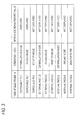
- Fig. 3 is a table showing relationships between the kind of electrodes and the operation mode, and the display of the impedance. As illustrated, the controller 6 controls the display so that the impedance measurement value is displayed only in the case where disposable pads are used as the electrodes 14, and the operation mode is the defibrillation mode or the pacing mode. In another case, the controller 6 controls the display so that the impedance measurement value is not displayed.
- Fig. 4 shows an example of a display of an impedance measurement value in the displaying section 7.
- the controller 6 controls an impedance display area 100 so as to be displayed on the display screen of the displaying section 7.
- the impedance display area 100 has an impedance display bar 101 showing that the higher the position in the screen, the higher the impedance, and, the lower the position in the screen, the lower the impedance.
- the current impedance measurement value is indicated by a pointer 102.
- a reference value (upper limit) 103 and another reference value (lower limit) 104 are displayed in the impedance display area 100.
- the reference value (upper limit) 103 is a value indicating that, when the impedance value is equal to or higher than the value, the treatment effect (effect of defibrillation or pacing) is very low.
- the reference value (lower limit) 104 is a value indicating that, when the impedance value is equal to or lower than the value, the treatment effect (effect of defibrillation or pacing) is very low.
- the two reference values are displayed. The invention is not limited to this. It is requested that at least one reference value is displayed.
- the user refers the impedance display area 100 to check whether the defibrillation or the pacing exerts sufficient effects or not.
- the display example of Fig. 4 is a mere example, and it is a matter of course that another kind of display may be performed.
- the displaying section 7 may display the impedance measurement value not by using an impedance display bar but by using a circle graph or the like.
- the controller 6 may control the displaying section 7 so as to display the impedance measurement value as it is or as a numeral on the display screen.
- the impedance measurement value is displayed on the displaying section 7.
- the invention is not limited to this.
- the impedance measurement value may not be visually output, but may be audibly output by the sound generating section 8. Namely, the impedance measurement value is requested to be output toward the user by the outputting section (the displaying section 7 and the sound generating section 8).
- the controller 6 may control the defibrillator so as not to perform defibrillation.
- the treatment effect for example, the disposable pads are detached or about to be detached
- an electrical shock is not applied to the rescue target.
- the controller 6 may output information (alarm) indicating this situation.
- the alarm may be one of an audio alarm (for example, voice guidance "The contact impedance is excessively high, therefore the treatment effect is very low”.) and a visual alarm (for example, the impedance measurement value is caused to blink to become prominent). According to the configuration, the user can recognize more clearly the situation where the treatment effect is low.
- the controller 6 may perform a similar process with respect to the reference value (lower limit) 104.
- Fig. 5 is a flowchart showing the flow of the process of displaying the impedance by the controller 6.
- the controller 6 determines whether disposable pads are connected to the connector 12 as the electrodes 14 or not (S11). If disposable pads are not connected (S11 : No), the controller 6 controls the displaying section 7 so as not to display the impedance measurement value thereon (S14). If disposable pads are connected (S11 : Yes), the controller 6 determines whether the operation mode is the defibrillation mode or the pacing mode (S12). If the mode is not the defibrillation mode or the pacing mode (S12: No), the controller 6 controls the displaying section 7 so as not to display the impedance measurement value thereon (S14). By contrast, if the mode is the defibrillation mode or the pacing mode (S12: Yes), the controller 6 controls the displaying section 7 so as to display the impedance measurement value thereon (S13).
- the controller 6 controls the impedance measurement value to be output only when the display of the impedance measurement value is significant. Namely, the user of the defibrillator 1 can refer the impedance measurement value only when it is necessary. Since the impedance measurement value can be known only when it is necessary, the user of the defibrillator 1 can perform appropriate defibrillation or pacing without being confused.
- the user of the defibrillator 1 can perform defibrillation or pacing after it is adequately determined whether the situation where the treatment effect is high is obtained or not. For example, the user of the defibrillator 1 can know a situation where the disposable pads are about to be detached. Therefore, a more appropriate rescue procedure can be applied to the rescue target.
- the impedance measurement value can be visually displayed on the displaying section 7 (in other words, the display screen). Therefore, the user of the defibrillator 1 can visually know the state of the impedance of the electrodes 14.
- the displaying section 7 displays as shown in Fig. 4 , together with the impedance measurement value (pointer 102), the reference value (upper limit) 103 (the value indicating that, when the impedance value is equal to or higher than the value, the treatment effect is very low), and the reference value (lower limit) 104 (the value indicating that, when the impedance value is equal to or lower than the value, the treatment effect is very low).
- the user of the defibrillator 1 who refers the display can easily know not only whether a situation where defibrillation or pacing can be performed is attained or not, but also the degree by which the current status of the electrodes 14 is appropriate for defibrillation or pacing. Therefore, the user of the defibrillator 1 can know the state where the treatment can be performed but exerts not so high effects, and improve the state.
- the controller 6 determines whether the impedance measurement value is to be displayed or not. Only in the case of the operation mode in which the impedance measurement value is to be referred, the controller 6 causes the impedance measurement value to be displayed (output). Therefore, the user of the defibrillator 1 can refer the impedance measurement value of the electrodes 14 (disposable pads) only in the case of the operation mode in which the impedance measurement value is necessary.
- the impedance of the electrodes 14 does not largely affect the monitoring operation.
- the impedance measurement value is not displayed (output). Therefore, the display on the display screen can be made appropriate for the monitor mode. Moreover, the user of the defibrillator 1 can be prevented from accidentally referring the impedance measurement value, and concentrate on the rescue procedure without being confused.
- the impedance measurement value is displayed (output). Therefore, the user of the defibrillator 1 can easily know whether adequate defibrillation or pacing is performed or not.
- the controller 6 may controls the displaying section so that, when disposable pads are connected, the impedance measurement value is always displayed irrespective of the operation mode.
- the user can refer the impedance measurement value only when disposable pads are used. While avoiding a situation where, when electrodes of another kind (external paddles or internal paddles) are connected, an unnecessary impedance measurement value is displayed, therefore, it is possible to check whether the treatment effect is sufficient or not when disposable pads are used.
- the controller 6 may control the displaying section so that, without considering the kind of the electrodes 14, the impedance measurement value is displayed depending on the operation mode.
- the accuracy of the provision of information is low as compared to the case where the kind of the electrodes 14 is considered, the user cannot refer the impedance measurement value in the case of the monitor mode.
- the operation mode is not considered, therefore, the user can operate the defibrillator without being confused.
- the timings when the impedance measuring section 13 measures the impedance may be limited to the case where the electrodes 14 and the operation mode satisfy predetermined conditions (for example, the conditions of Fig. 3 ). Alternatively, the measurement may be always performed irrespective of the kind of the electrodes 14 and the operation mode. In any case, the output of the impedance measurement value is controlled by the controller 6.
- the controller 6 may control the impedance measuring section 13 so as to measure the impedance, and the displaying section so that the impedance measurement value is displayed.
- the controller 6 may control the impedance measuring section 13 so as to always measure the impedance, and the displaying section so that, only when the electrodes 14 and the operation mode satisfy predetermined conditions (for example, the conditions of Fig. 3 ), the impedance measurement value is displayed.
- the controller controls the impedance measurement value to be output only when the output of the impedance measurement value is appropriate. Therefore, the user of the defibrillator can adequately refer the impedance measurement value only when it is necessary. Since the impedance measurement value can be adequately referred, defibrillation (or pacing) can be performed in a state where a high treatment effect is achieved.
- the presently disclosed subject matter can provide a defibrillator which is easily operated in a state where a high treatment effect is achieved, and a method of controlling such a defibrillator.
Landscapes
- Health & Medical Sciences (AREA)
- Engineering & Computer Science (AREA)
- Cardiology (AREA)
- Radiology & Medical Imaging (AREA)
- Biomedical Technology (AREA)
- Nuclear Medicine, Radiotherapy & Molecular Imaging (AREA)
- Life Sciences & Earth Sciences (AREA)
- Animal Behavior & Ethology (AREA)
- General Health & Medical Sciences (AREA)
- Public Health (AREA)
- Veterinary Medicine (AREA)
- Heart & Thoracic Surgery (AREA)
- Human Computer Interaction (AREA)
- Electrotherapy Devices (AREA)
- Measurement And Recording Of Electrical Phenomena And Electrical Characteristics Of The Living Body (AREA)
Abstract
Description
- The presently disclosed subject matter relates to a defibrillator and a method of controlling a defibrillator.
- A defibrillator applies an electrical stimulus to arrhythmia such as ventricular fibrillation (VF) or ventricular tachycardia (VT) to perform defibrillation or cardioversion. A defibrillator which is used in a medical facility can be connected to external paddles, internal paddles, disposable pads, and the like which function as electrodes to be contacted with the body surface of the rescue target (patient). The user (mainly, a doctor) of a defibrillator selects the kind of electrodes in accordance with the state or the like of the rescue target, and then operates the defibrillator. In the case where disposable pads are to be used as electrodes, it is important that the impedance between the disposable pads and the body surface of the rescue target is low.
-
JP-A-2013-240466 JP-A-2013-240466 - As described above, a defibrillator which is used in a medical facility can use various kinds of electrodes (external paddles, internal paddles, and disposable pads). In the case where disposable pads are used, the impedance with the body surface is very useful information. By contrast, in the case where electrodes other than disposable pads are used, consideration of such impedance is not important. Depending on an operation mode of a defibrillator, it is not always necessary to refer information of a measurement value of an impedance (hereinafter, the measured value is referred to as "impedance measurement value").
- In the related art including
JP-A-2013-240466 - The presently disclosed subject matter may provide a defibrillator which is easily operated in a state where a high treatment effect is achieved, and a method of controlling such a defibrillator.
- The defibrillator may comprise: an impedance measuring section which is configured to obtain an impedance measurement value between a living body of a rescue target and electrodes; a controller which is configured to detect a kind of the electrodes, and which, based on the detected kind of the electrodes, is configured to perform determination of whether the impedance measurement value is to be output or not; and an outputting section which, based on the determination, is configured to output the impedance measurement value.
- The defibrillator may comprise: an impedance measuring section which is configured to obtain an impedance measurement value between a living body of a rescue target and electrodes; a controller which is configured to detect an operation mode of the defibrillator, and which, based on the detected operation mode, is configured to perform determination of whether the impedance measurement value is to be output or not; and an outputting section which, based on the determination, is configured to output the impedance measurement value.
-
-
Fig. 1 is a perspective view showing the external configuration of adefibrillator 1 ofEmbodiment 1. -
Fig. 2 is a block diagram showing the internal configuration of thedefibrillator 1 ofEmbodiment 1. -
Fig. 3 is a table showing an algorithm of outputting an impedance by acontroller 6 inEmbodiment 1. -
Fig. 4 is a view showing an example of a display screen of an impedance measurement value in a displayingsection 7 inEmbodiment 1. -
Fig. 5 is a flowchart showing a determination of a display of an impedance measurement value by thecontroller 6 inEmbodiment 1. - Hereinafter, an embodiment of the presently disclosed subject matter will be described with reference to the drawings.
Fig. 1 is a perspective view showing an example of the external configuration of adefibrillator 1 of the embodiment. The configuration of thedefibrillator 1 shown inFig. 1 is a mere example, and it is a matter of course that the defibrillator may have another shape.Fig. 1 shows a state where external paddles are attached to thedefibrillator 1. Thedefibrillator 1 is used in, for example, a medical facility or an ambulance under operation by the user (mainly, a doctor). The user refers an electrocardiogram of the rescue target (patient). If it is determined that an electrical shock is necessary, the user performs a charging process, and then applies an electrical shock to the rescue target. -
Fig. 2 is a block diagram showing the internal configuration of the defibrillator of the embodiment. Thedefibrillator 1 has a power supplying section 2, astorage section 3, a communicatingsection 4, anoperating section 5, acontroller 6, a displayingsection 7, asound generating section 8, anelectrocardiogram signal amplifier 9, a high-voltage generating section 10, a high-voltage capacitor 11, aconnector 12, and an impedance measuringsection 13. Thedefibrillator 1 is connected toelectrodes 14 through theconnector 12. - The
electrodes 14 include so-called external paddles (external electrodes), internal paddles (internal electrodes), and disposable pads (so-called adhesive disposable pads). Theelectrodes 14 are contacted with the body surface of the rescue target. In the case where disposable pads are used as theelectrodes 14, it is important that the impedance between the body surface of the rescue target and the disposable pads is in a low state. When the impedance is high, the effect of defibrillation (electrical shock) is not sufficient, and there is a possibility that the disposable pads may be disconnected during defibrillation. - The
defibrillator 1 operates in various operation modes. Examples of the operation modes are a monitor mode and a defibrillation mode. The monitor mode is an operation mode in which biological information of the rescue target is acquired and displayed on the displayingsection 7 that will be described later. The defibrillation mode is an operation mode in which defibrillation is performed on the rescue target. Thedefibrillator 1 may be configured so as to operate also in a pacing mode. The pacing mode is an operation mode for regulating contractions of the right and left ventricles. - The
defibrillator 1 may be configured so as to have an SpO2 adaptor and a connection interface with a CO2 sensor. Thedefibrillator 1 may have an incorporated printer and the like. - Hereinafter, the configurations and operations of the processing sections in the
defibrillator 1 will be described. The power supplying section 2 is a battery which supplies electric power to the processing sections in thedefibrillator 1. The power supplying section 2 performs voltage conversion by using a voltage controlling mechanism which is not shown, and supplies electric power to the processing sections. - The
storage section 3 stores programs which are necessary for enabling thedefibrillator 1 to operate, audio data, adjustment values, measured electrocardiogram waveforms, and the like. For example, thestorage section 3 is a secondary storage device such as a hard disk drive. A part of thestorage section 3 may be configured by a device which is attachable to and detachable from the defibrillator 1 (for example, a USB (Universal Serial Bus) memory). - The communicating
section 4 is a wireless interface which communicates with medical servers and the like on a network. The communicatingsection 4 transmits acquired electrocardiogram waveforms and the like to the medical servers and the like, as required. It is not always necessary for thedefibrillator 1 to include the communicatingsection 4. - The
operating section 5 is an interface for enabling the user to operate thedefibrillator 1. For example, theoperating section 5 is configured by knobs, buttons, and the like which are disposed on the surface of the case in order to designate the charged energy amount. - The
controller 6 controls various operations of thedefibrillator 1. Specifically, thecontroller 6 performs various operation controls such as charging/discharging of energy, a sequence control, an electrocardiogram analysis, and a control of an audio output. Thecontroller 6 is configured by a CPU (Central Processing Unit), a gate array, an A/D converter, etc. Thecontroller 6 further performs a control of a display of an impedance measurement value on the displayingsection 7, as described later. - The displaying
section 7 visually outputs the state of thedefibrillator 1 and the like. For example, the displayingsection 7 is configured by a liquid crystal display device (TFT LCD screen) disposed on the surface of the case of thedefibrillator 1, a control circuit for the device, etc. Thesound generating section 8 audibly outputs (sound outputs) the state of thedefibrillator 1 and the like. The displayingsection 7 and thesound generating section 8 can be deemed as one mode of an outputting section which outputs the state of thedefibrillator 1, the impedance measurement value of theelectrodes 14 which will be described later, and the like. - The
electrocardiogram signal amplifier 9 performs filtering and an amplification process on an electrocardiogram signal obtained from theelectrodes 14 which are connected to theconnector 12. The high-voltage generating section 10 charges and discharges energy which is to be used in defibrillation, in accordance with the control of thecontroller 6. Energy for defibrillation is charge in the high-voltage capacitor 11. - The
connector 12 is a connection interface which is used in the connection with theelectrodes 14 which are to be contacted to the body surface of the rescue target. Theconnector 12 has connector pins corresponding to the kinds of theelectrodes 14. Theelectrodes 14 are connected to the corresponding ones of the connector pins. - As described above, the
electrodes 14 are external paddles (external electrodes), internal paddles (internal electrodes), disposable pads (so-called disposable adhesive pads), etc. During execution of defibrillation or pacing, theelectrodes 14 are contacted with the body surface of the rescue target. Theelectrodes 14 are attached to theconnector 12. - The
impedance measuring section 13 measures the impedance between theelectrodes 14 and the body surface of the rescue target. Theimpedance measuring section 13 supplies the measurement value of the measured impedance (impedance measurement value) to thecontroller 6. - The
controller 6 detects the connection state of theconnector 12 and theelectrodes 14, particularly whether a state where disposable pads are connected to the connector is obtained or not. In the detecting process, for example, the determination is performed based on the connection states of the connector pins constituting the above-describedconnector 12. Thecontroller 6 further determines the kind of the operation mode. Then, thecontroller 6 determines whether the impedance measurement value is to be displayed on the displayingsection 7 or not, based on the kind of theconnected electrodes 14, and the operation mode. -
Fig. 3 is a table showing relationships between the kind of electrodes and the operation mode, and the display of the impedance. As illustrated, thecontroller 6 controls the display so that the impedance measurement value is displayed only in the case where disposable pads are used as theelectrodes 14, and the operation mode is the defibrillation mode or the pacing mode. In another case, thecontroller 6 controls the display so that the impedance measurement value is not displayed. -
Fig. 4 shows an example of a display of an impedance measurement value in the displayingsection 7. In accordance with the table ofFig. 3 , only in the case where the impedance measurement value is to be displayed, thecontroller 6 controls animpedance display area 100 so as to be displayed on the display screen of the displayingsection 7. Theimpedance display area 100 has animpedance display bar 101 showing that the higher the position in the screen, the higher the impedance, and, the lower the position in the screen, the lower the impedance. The current impedance measurement value is indicated by apointer 102. Also a reference value (upper limit) 103 and another reference value (lower limit) 104 are displayed in theimpedance display area 100. The reference value (upper limit) 103 is a value indicating that, when the impedance value is equal to or higher than the value, the treatment effect (effect of defibrillation or pacing) is very low. Similarly, the reference value (lower limit) 104 is a value indicating that, when the impedance value is equal to or lower than the value, the treatment effect (effect of defibrillation or pacing) is very low. In the example ofFig. 4 , the two reference values are displayed. The invention is not limited to this. It is requested that at least one reference value is displayed. - The user refers the
impedance display area 100 to check whether the defibrillation or the pacing exerts sufficient effects or not. - The display example of
Fig. 4 is a mere example, and it is a matter of course that another kind of display may be performed. For example, the displayingsection 7 may display the impedance measurement value not by using an impedance display bar but by using a circle graph or the like. Moreover, thecontroller 6 may control the displayingsection 7 so as to display the impedance measurement value as it is or as a numeral on the display screen. - In the above description, the impedance measurement value is displayed on the displaying
section 7. The invention is not limited to this. For example, the impedance measurement value may not be visually output, but may be audibly output by thesound generating section 8. Namely, the impedance measurement value is requested to be output toward the user by the outputting section (the displayingsection 7 and the sound generating section 8). - When the impedance measurement value is higher than the above-described
reference value 103, thecontroller 6 may control the defibrillator so as not to perform defibrillation. According to the configuration, in the case where the treatment effect is low (for example, the disposable pads are detached or about to be detached), an electrical shock is not applied to the rescue target. - When the difference between the impedance measurement value and the reference value (upper limit) 103 satisfies predetermined conditions (specifically, when the impedance measurement value is higher than the reference value (upper limit) 103, or when the difference between the impedance measurement value and the reference value (upper limit) 103 is within a predetermined range), the
controller 6 may output information (alarm) indicating this situation. In this case, the alarm may be one of an audio alarm (for example, voice guidance "The contact impedance is excessively high, therefore the treatment effect is very low".) and a visual alarm (for example, the impedance measurement value is caused to blink to become prominent). According to the configuration, the user can recognize more clearly the situation where the treatment effect is low. Thecontroller 6 may perform a similar process with respect to the reference value (lower limit) 104. - Next, the flow of the control of displaying the impedance by the
controller 6 will be redescribed with reference toFig. 5. Fig. 5 is a flowchart showing the flow of the process of displaying the impedance by thecontroller 6. - The
controller 6 determines whether disposable pads are connected to theconnector 12 as theelectrodes 14 or not (S11). If disposable pads are not connected (S11 : No), thecontroller 6 controls the displayingsection 7 so as not to display the impedance measurement value thereon (S14). If disposable pads are connected (S11 : Yes), thecontroller 6 determines whether the operation mode is the defibrillation mode or the pacing mode (S12). If the mode is not the defibrillation mode or the pacing mode (S12: No), thecontroller 6 controls the displayingsection 7 so as not to display the impedance measurement value thereon (S14). By contrast, if the mode is the defibrillation mode or the pacing mode (S12: Yes), thecontroller 6 controls the displayingsection 7 so as to display the impedance measurement value thereon (S13). - Then, effects of the
defibrillator 1 of the embodiment will be described. As described above, thecontroller 6 controls the impedance measurement value to be output only when the display of the impedance measurement value is significant. Namely, the user of thedefibrillator 1 can refer the impedance measurement value only when it is necessary. Since the impedance measurement value can be known only when it is necessary, the user of thedefibrillator 1 can perform appropriate defibrillation or pacing without being confused. - Since the state of the impedance is output, the user of the
defibrillator 1 can perform defibrillation or pacing after it is adequately determined whether the situation where the treatment effect is high is obtained or not. For example, the user of thedefibrillator 1 can know a situation where the disposable pads are about to be detached. Therefore, a more appropriate rescue procedure can be applied to the rescue target. - The impedance measurement value can be visually displayed on the displaying section 7 (in other words, the display screen). Therefore, the user of the
defibrillator 1 can visually know the state of the impedance of theelectrodes 14. - In the case where the impedance measurement value is to be displayed, for example, the displaying
section 7 displays as shown inFig. 4 , together with the impedance measurement value (pointer 102), the reference value (upper limit) 103 (the value indicating that, when the impedance value is equal to or higher than the value, the treatment effect is very low), and the reference value (lower limit) 104 (the value indicating that, when the impedance value is equal to or lower than the value, the treatment effect is very low). The user of thedefibrillator 1 who refers the display can easily know not only whether a situation where defibrillation or pacing can be performed is attained or not, but also the degree by which the current status of theelectrodes 14 is appropriate for defibrillation or pacing. Therefore, the user of thedefibrillator 1 can know the state where the treatment can be performed but exerts not so high effects, and improve the state. - While considering also the operation mode in addition to the kind of the
electrodes 14, thecontroller 6 determines whether the impedance measurement value is to be displayed or not. Only in the case of the operation mode in which the impedance measurement value is to be referred, thecontroller 6 causes the impedance measurement value to be displayed (output). Therefore, the user of thedefibrillator 1 can refer the impedance measurement value of the electrodes 14 (disposable pads) only in the case of the operation mode in which the impedance measurement value is necessary. - In the case where the
defibrillator 1 operates in the monitor mode, for example, the impedance of theelectrodes 14 does not largely affect the monitoring operation. In this case, the impedance measurement value is not displayed (output). Therefore, the display on the display screen can be made appropriate for the monitor mode. Moreover, the user of thedefibrillator 1 can be prevented from accidentally referring the impedance measurement value, and concentrate on the rescue procedure without being confused. - By contrast, in the case of the defibrillation mode or the pacing mode, the impedance measurement value is displayed (output). Therefore, the user of the
defibrillator 1 can easily know whether adequate defibrillation or pacing is performed or not. - Although the invention conducted by the inventors has been specifically described based on the embodiments, the invention is not limited to the above-described embodiments, and it is a matter of course that various changes can be made without departing from the spirit of the invention.
- For example, the
controller 6 may controls the displaying section so that, when disposable pads are connected, the impedance measurement value is always displayed irrespective of the operation mode. In this case, although the accuracy of the provision of information is low as compared to the case where the operation mode is considered, the user can refer the impedance measurement value only when disposable pads are used. While avoiding a situation where, when electrodes of another kind (external paddles or internal paddles) are connected, an unnecessary impedance measurement value is displayed, therefore, it is possible to check whether the treatment effect is sufficient or not when disposable pads are used. - Alternatively, the
controller 6 may control the displaying section so that, without considering the kind of theelectrodes 14, the impedance measurement value is displayed depending on the operation mode. In this case, although the accuracy of the provision of information is low as compared to the case where the kind of theelectrodes 14 is considered, the user cannot refer the impedance measurement value in the case of the monitor mode. As compared to the prior art in which the operation mode is not considered, therefore, the user can operate the defibrillator without being confused. - The timings when the
impedance measuring section 13 measures the impedance may be limited to the case where theelectrodes 14 and the operation mode satisfy predetermined conditions (for example, the conditions ofFig. 3 ). Alternatively, the measurement may be always performed irrespective of the kind of theelectrodes 14 and the operation mode. In any case, the output of the impedance measurement value is controlled by thecontroller 6. - Only when the
electrodes 14 and the operation mode satisfy predetermined conditions (for example, the conditions ofFig. 3 ), thecontroller 6 may control theimpedance measuring section 13 so as to measure the impedance, and the displaying section so that the impedance measurement value is displayed. Alternatively, thecontroller 6 may control theimpedance measuring section 13 so as to always measure the impedance, and the displaying section so that, only when theelectrodes 14 and the operation mode satisfy predetermined conditions (for example, the conditions ofFig. 3 ), the impedance measurement value is displayed. - According to an aspect of the presently disclosed subject matter, the controller controls the impedance measurement value to be output only when the output of the impedance measurement value is appropriate. Therefore, the user of the defibrillator can adequately refer the impedance measurement value only when it is necessary. Since the impedance measurement value can be adequately referred, defibrillation (or pacing) can be performed in a state where a high treatment effect is achieved.
- The presently disclosed subject matter can provide a defibrillator which is easily operated in a state where a high treatment effect is achieved, and a method of controlling such a defibrillator.
Claims (9)
- A defibrillator comprising:an impedance measuring section which is configured to obtain an impedance measurement value between a living body of a rescue target and electrodes;a controller which is configured to detect a kind of the electrodes, and which, based on the detected kind of the electrodes, is configured to perform determination of whether the impedance measurement value is to be output or not; andan outputting section which, based on the determination, is configured to output the impedance measurement value.
- The defibrillator according to claim 1, wherein
the controller, based on an operation mode of the defibrillator in addition to the detected kind of the electrodes, is configured to perform the determination of whether the impedance measurement value is to be output or not. - The defibrillator according to claim 2, wherein,
in a case where the electrodes are disposable pads, and the operation mode is a pacing mode or a defibrillation mode, the controller determines that the impedance measurement value is to be output. - The defibrillator according to any one of claims 1 to 3, wherein
the outputting section displays the impedance measurement value, and one or more reference value which functions as a reference for determining whether a treatment effect is high or not, on a display screen. - The defibrillator according to claim 4, wherein
the outputting section is configured to audibly output the impedance measurement value. - The defibrillator according to claim 4 or 5, wherein,
in a case where a difference between the impedance measurement value and the reference value satisfies a predetermined condition, the controller controls the outputting section to output an alarm. - A defibrillator comprising:an impedance measuring section which is configured to obtain an impedance measurement value between a living body of a rescue target and electrodes;a controller which is configured to detect an operation mode of the defibrillator, and which, based on the detected operation mode, is configured to perform determination of whether the impedance measurement value is to be output or not; andan outputting section which, based on the determination, is configured to output the impedance measurement value.
- A method of controlling a defibrillator which is configured to apply an electrical shock to a rescue target, the method comprising:obtaining an impedance measurement value between a living body of the rescue target and electrodes;detecting a kind of the electrodes, and, based on the detected kind of the electrodes, performing determination of whether the impedance measurement value is to be output or not; andbased on the determination, outputting the impedance measurement value.
- A method of controlling a defibrillator which is configured to apply an electrical shock to a rescue target, the method comprising:obtaining an impedance measurement value between a living body of the rescue target and electrodes;detecting an operation mode of the defibrillator, and, based on the detected operation mode, performing determination of whether the impedance measurement value is to be output or not; andbased on the determination, outputting the impedance measurement value.
Applications Claiming Priority (1)
| Application Number | Priority Date | Filing Date | Title |
|---|---|---|---|
| JP2014162052A JP6289303B2 (en) | 2014-08-08 | 2014-08-08 | Defibrillator |
Publications (3)
| Publication Number | Publication Date |
|---|---|
| EP2982410A2 true EP2982410A2 (en) | 2016-02-10 |
| EP2982410A3 EP2982410A3 (en) | 2016-03-23 |
| EP2982410B1 EP2982410B1 (en) | 2017-08-23 |
Family
ID=53773271
Family Applications (1)
| Application Number | Title | Priority Date | Filing Date |
|---|---|---|---|
| EP15178585.4A Not-in-force EP2982410B1 (en) | 2014-08-08 | 2015-07-28 | Defibrillator and method of controlling defibrillator |
Country Status (4)
| Country | Link |
|---|---|
| US (1) | US9630016B2 (en) |
| EP (1) | EP2982410B1 (en) |
| JP (1) | JP6289303B2 (en) |
| CN (1) | CN105363128B (en) |
Cited By (1)
| Publication number | Priority date | Publication date | Assignee | Title |
|---|---|---|---|---|
| WO2017167822A1 (en) * | 2016-03-31 | 2017-10-05 | Koninklijke Philips N.V. | Defibrillator paddles with use indicators |
Families Citing this family (4)
| Publication number | Priority date | Publication date | Assignee | Title |
|---|---|---|---|---|
| JP6700081B2 (en) * | 2016-03-29 | 2020-05-27 | フクダ電子株式会社 | Defibrillator |
| CN105879228A (en) * | 2016-04-01 | 2016-08-24 | 江苏鸿都医疗科技有限公司 | Portable automatic external defibrillator with disposable electrodes |
| GB2598299B (en) * | 2020-08-20 | 2023-10-04 | Actegy Ltd | Apparatus for detecting electrical conductivity |
| US12233276B2 (en) | 2020-12-03 | 2025-02-25 | Physio-Control, Inc. | Automatic lead switching |
Citations (1)
| Publication number | Priority date | Publication date | Assignee | Title |
|---|---|---|---|---|
| JP2013240466A (en) | 2012-05-21 | 2013-12-05 | Heartsine Technologies Ltd | Testing of defibrillator electrode |
Family Cites Families (13)
| Publication number | Priority date | Publication date | Assignee | Title |
|---|---|---|---|---|
| US5441520A (en) * | 1993-04-06 | 1995-08-15 | Hewlett-Packard Corporation | Defibrillator patient connection system with automatic identification |
| US6016445A (en) | 1996-04-16 | 2000-01-18 | Cardiotronics | Method and apparatus for electrode and transthoracic impedance estimation |
| US5792185A (en) | 1997-01-24 | 1998-08-11 | Hewlett-Packard Company | Apparatus, method, and system which accurately discriminates between defibrillation electrodes and heart monitoring electrodes |
| US6007532A (en) * | 1997-08-29 | 1999-12-28 | 3M Innovative Properties Company | Method and apparatus for detecting loss of contact of biomedical electrodes with patient skin |
| US6560485B2 (en) * | 2001-03-27 | 2003-05-06 | Koninklijke Philips Electronics N.V. | Four contact identification defibrillator electrode system |
| WO2005000399A1 (en) | 2003-06-27 | 2005-01-06 | Koninklijke Philips Electronics N.V. | Compensation for cardiac shunt currents during defibrillation |
| US7340294B2 (en) * | 2005-08-11 | 2008-03-04 | The General Electric Company | Impedance measurement apparatus for assessment of biomedical electrode interface quality |
| US8180442B2 (en) * | 2007-12-14 | 2012-05-15 | Greatbatch Ltd. | Deriving patient activity information from sensed body electrical information |
| JP5196311B2 (en) | 2008-09-12 | 2013-05-15 | 日本光電工業株式会社 | Disposable electrode and automatic expiration date recognition device thereof |
| CN101518667A (en) * | 2009-03-20 | 2009-09-02 | 武汉依瑞德医疗设备新技术有限公司 | Intelligent intermediate-frequency bi-directional square wave defibrillation method |
| JP4545216B1 (en) * | 2009-03-23 | 2010-09-15 | 日本ライフライン株式会社 | Intracardiac defibrillation catheter system |
| US9180288B2 (en) * | 2011-09-01 | 2015-11-10 | Zoll Medical Corporation | Medical equipment electrodes |
| JP5939793B2 (en) * | 2011-12-27 | 2016-06-22 | フクダ電子株式会社 | External defibrillator |
-
2014
- 2014-08-08 JP JP2014162052A patent/JP6289303B2/en active Active
-
2015
- 2015-07-14 US US14/798,814 patent/US9630016B2/en not_active Expired - Fee Related
- 2015-07-28 EP EP15178585.4A patent/EP2982410B1/en not_active Not-in-force
- 2015-07-31 CN CN201510463321.XA patent/CN105363128B/en not_active Expired - Fee Related
Patent Citations (1)
| Publication number | Priority date | Publication date | Assignee | Title |
|---|---|---|---|---|
| JP2013240466A (en) | 2012-05-21 | 2013-12-05 | Heartsine Technologies Ltd | Testing of defibrillator electrode |
Cited By (1)
| Publication number | Priority date | Publication date | Assignee | Title |
|---|---|---|---|---|
| WO2017167822A1 (en) * | 2016-03-31 | 2017-10-05 | Koninklijke Philips N.V. | Defibrillator paddles with use indicators |
Also Published As
| Publication number | Publication date |
|---|---|
| CN105363128A (en) | 2016-03-02 |
| JP2016036561A (en) | 2016-03-22 |
| JP6289303B2 (en) | 2018-03-07 |
| EP2982410A3 (en) | 2016-03-23 |
| US20160038750A1 (en) | 2016-02-11 |
| US9630016B2 (en) | 2017-04-25 |
| CN105363128B (en) | 2019-12-10 |
| EP2982410B1 (en) | 2017-08-23 |
Similar Documents
| Publication | Publication Date | Title |
|---|---|---|
| EP2982410B1 (en) | Defibrillator and method of controlling defibrillator | |
| EP3797827B1 (en) | Electronic electrocardiogram calipers | |
| US11642104B2 (en) | Systems and methods for automated fluid response measurement | |
| US20090177243A1 (en) | Transcranial electrostimulation device | |
| US20090138059A1 (en) | Heart Defibrillator With Contactless ECG Sensor For Diagnostics/Effectivity Feedback | |
| JP2018526075A (en) | Device, system and method for non-invasively monitoring physiological parameters | |
| CN1463194A (en) | Integrated cardiac resuscitation system with ability to detect perfusion | |
| CN102125431B (en) | Nerve plexus stimulation system, nerve plexus stimulator and nerve plexus stimulation method | |
| JP2019530528A (en) | Quantitative neuromuscular block detection system and method | |
| CN105188841A (en) | Defibrillator and method using limb leads for artifact free ECG | |
| CN112839576B (en) | Cardiopulmonary resuscitation guidance method, guidance apparatus, and computer-readable storage medium | |
| EP4294507B1 (en) | Automated external defibrillator and power supply adapted for non-clinical use | |
| BRPI0806147A2 (en) | automatic external defibrillator and method of operation | |
| CN107690340B (en) | Method and apparatus for detecting CPR chest compression status without the use of a separate compression meter | |
| KR20150095439A (en) | System and method for Biological information measuring | |
| CN202078314U (en) | Nerve plexus stimulation system and nerve plexus stimulator | |
| JP6656815B2 (en) | Biological information monitor | |
| US12551696B2 (en) | Electrodes with usability indicator | |
| KR101658680B1 (en) | Apparatus and method for monitoring facial nerve | |
| RU2531695C2 (en) | Cardiac pacemaker | |
| KR101752303B1 (en) | Implantable biomaterial sensing device | |
| US20250195903A1 (en) | Defibrillator | |
| JP2012024388A (en) | Cardiac therapy equipment, and cardiac therapy system | |
| JP2024156432A (en) | Connecting Devices | |
| CN121695413A (en) | Pelvic floor muscle repair instrument, insertion state detection method, insertion state detection equipment and insertion state detection medium |
Legal Events
| Date | Code | Title | Description |
|---|---|---|---|
| PUAI | Public reference made under article 153(3) epc to a published international application that has entered the european phase |
Free format text: ORIGINAL CODE: 0009012 |
|
| AK | Designated contracting states |
Kind code of ref document: A2 Designated state(s): AL AT BE BG CH CY CZ DE DK EE ES FI FR GB GR HR HU IE IS IT LI LT LU LV MC MK MT NL NO PL PT RO RS SE SI SK SM TR |
|
| AX | Request for extension of the european patent |
Extension state: BA ME |
|
| PUAL | Search report despatched |
Free format text: ORIGINAL CODE: 0009013 |
|
| AK | Designated contracting states |
Kind code of ref document: A3 Designated state(s): AL AT BE BG CH CY CZ DE DK EE ES FI FR GB GR HR HU IE IS IT LI LT LU LV MC MK MT NL NO PL PT RO RS SE SI SK SM TR |
|
| AX | Request for extension of the european patent |
Extension state: BA ME |
|
| RIC1 | Information provided on ipc code assigned before grant |
Ipc: A61N 1/39 20060101AFI20160216BHEP |
|
| 17P | Request for examination filed |
Effective date: 20160729 |
|
| RBV | Designated contracting states (corrected) |
Designated state(s): AL AT BE BG CH CY CZ DE DK EE ES FI FR GB GR HR HU IE IS IT LI LT LU LV MC MK MT NL NO PL PT RO RS SE SI SK SM TR |
|
| GRAP | Despatch of communication of intention to grant a patent |
Free format text: ORIGINAL CODE: EPIDOSNIGR1 |
|
| INTG | Intention to grant announced |
Effective date: 20170407 |
|
| GRAS | Grant fee paid |
Free format text: ORIGINAL CODE: EPIDOSNIGR3 |
|
| GRAA | (expected) grant |
Free format text: ORIGINAL CODE: 0009210 |
|
| AK | Designated contracting states |
Kind code of ref document: B1 Designated state(s): AL AT BE BG CH CY CZ DE DK EE ES FI FR GB GR HR HU IE IS IT LI LT LU LV MC MK MT NL NO PL PT RO RS SE SI SK SM TR |
|
| REG | Reference to a national code |
Ref country code: GB Ref legal event code: FG4D |
|
| REG | Reference to a national code |
Ref country code: CH Ref legal event code: EP |
|
| REG | Reference to a national code |
Ref country code: AT Ref legal event code: REF Ref document number: 920690 Country of ref document: AT Kind code of ref document: T Effective date: 20170915 |
|
| REG | Reference to a national code |
Ref country code: IE Ref legal event code: FG4D |
|
| REG | Reference to a national code |
Ref country code: DE Ref legal event code: R096 Ref document number: 602015004255 Country of ref document: DE |
|
| REG | Reference to a national code |
Ref country code: NL Ref legal event code: MP Effective date: 20170823 |
|
| REG | Reference to a national code |
Ref country code: LT Ref legal event code: MG4D |
|
| REG | Reference to a national code |
Ref country code: AT Ref legal event code: MK05 Ref document number: 920690 Country of ref document: AT Kind code of ref document: T Effective date: 20170823 |
|
| PG25 | Lapsed in a contracting state [announced via postgrant information from national office to epo] |
Ref country code: NL Free format text: LAPSE BECAUSE OF FAILURE TO SUBMIT A TRANSLATION OF THE DESCRIPTION OR TO PAY THE FEE WITHIN THE PRESCRIBED TIME-LIMIT Effective date: 20170823 Ref country code: SE Free format text: LAPSE BECAUSE OF FAILURE TO SUBMIT A TRANSLATION OF THE DESCRIPTION OR TO PAY THE FEE WITHIN THE PRESCRIBED TIME-LIMIT Effective date: 20170823 Ref country code: NO Free format text: LAPSE BECAUSE OF FAILURE TO SUBMIT A TRANSLATION OF THE DESCRIPTION OR TO PAY THE FEE WITHIN THE PRESCRIBED TIME-LIMIT Effective date: 20171123 Ref country code: HR Free format text: LAPSE BECAUSE OF FAILURE TO SUBMIT A TRANSLATION OF THE DESCRIPTION OR TO PAY THE FEE WITHIN THE PRESCRIBED TIME-LIMIT Effective date: 20170823 Ref country code: AT Free format text: LAPSE BECAUSE OF FAILURE TO SUBMIT A TRANSLATION OF THE DESCRIPTION OR TO PAY THE FEE WITHIN THE PRESCRIBED TIME-LIMIT Effective date: 20170823 Ref country code: FI Free format text: LAPSE BECAUSE OF FAILURE TO SUBMIT A TRANSLATION OF THE DESCRIPTION OR TO PAY THE FEE WITHIN THE PRESCRIBED TIME-LIMIT Effective date: 20170823 Ref country code: LT Free format text: LAPSE BECAUSE OF FAILURE TO SUBMIT A TRANSLATION OF THE DESCRIPTION OR TO PAY THE FEE WITHIN THE PRESCRIBED TIME-LIMIT Effective date: 20170823 |
|
| PG25 | Lapsed in a contracting state [announced via postgrant information from national office to epo] |
Ref country code: IS Free format text: LAPSE BECAUSE OF FAILURE TO SUBMIT A TRANSLATION OF THE DESCRIPTION OR TO PAY THE FEE WITHIN THE PRESCRIBED TIME-LIMIT Effective date: 20171223 Ref country code: ES Free format text: LAPSE BECAUSE OF FAILURE TO SUBMIT A TRANSLATION OF THE DESCRIPTION OR TO PAY THE FEE WITHIN THE PRESCRIBED TIME-LIMIT Effective date: 20170823 Ref country code: LV Free format text: LAPSE BECAUSE OF FAILURE TO SUBMIT A TRANSLATION OF THE DESCRIPTION OR TO PAY THE FEE WITHIN THE PRESCRIBED TIME-LIMIT Effective date: 20170823 Ref country code: GR Free format text: LAPSE BECAUSE OF FAILURE TO SUBMIT A TRANSLATION OF THE DESCRIPTION OR TO PAY THE FEE WITHIN THE PRESCRIBED TIME-LIMIT Effective date: 20171124 Ref country code: PL Free format text: LAPSE BECAUSE OF FAILURE TO SUBMIT A TRANSLATION OF THE DESCRIPTION OR TO PAY THE FEE WITHIN THE PRESCRIBED TIME-LIMIT Effective date: 20170823 Ref country code: BG Free format text: LAPSE BECAUSE OF FAILURE TO SUBMIT A TRANSLATION OF THE DESCRIPTION OR TO PAY THE FEE WITHIN THE PRESCRIBED TIME-LIMIT Effective date: 20171123 Ref country code: RS Free format text: LAPSE BECAUSE OF FAILURE TO SUBMIT A TRANSLATION OF THE DESCRIPTION OR TO PAY THE FEE WITHIN THE PRESCRIBED TIME-LIMIT Effective date: 20170823 |
|
| PG25 | Lapsed in a contracting state [announced via postgrant information from national office to epo] |
Ref country code: DK Free format text: LAPSE BECAUSE OF FAILURE TO SUBMIT A TRANSLATION OF THE DESCRIPTION OR TO PAY THE FEE WITHIN THE PRESCRIBED TIME-LIMIT Effective date: 20170823 Ref country code: CZ Free format text: LAPSE BECAUSE OF FAILURE TO SUBMIT A TRANSLATION OF THE DESCRIPTION OR TO PAY THE FEE WITHIN THE PRESCRIBED TIME-LIMIT Effective date: 20170823 Ref country code: RO Free format text: LAPSE BECAUSE OF FAILURE TO SUBMIT A TRANSLATION OF THE DESCRIPTION OR TO PAY THE FEE WITHIN THE PRESCRIBED TIME-LIMIT Effective date: 20170823 |
|
| REG | Reference to a national code |
Ref country code: DE Ref legal event code: R097 Ref document number: 602015004255 Country of ref document: DE |
|
| PG25 | Lapsed in a contracting state [announced via postgrant information from national office to epo] |
Ref country code: IT Free format text: LAPSE BECAUSE OF FAILURE TO SUBMIT A TRANSLATION OF THE DESCRIPTION OR TO PAY THE FEE WITHIN THE PRESCRIBED TIME-LIMIT Effective date: 20170823 Ref country code: SK Free format text: LAPSE BECAUSE OF FAILURE TO SUBMIT A TRANSLATION OF THE DESCRIPTION OR TO PAY THE FEE WITHIN THE PRESCRIBED TIME-LIMIT Effective date: 20170823 Ref country code: EE Free format text: LAPSE BECAUSE OF FAILURE TO SUBMIT A TRANSLATION OF THE DESCRIPTION OR TO PAY THE FEE WITHIN THE PRESCRIBED TIME-LIMIT Effective date: 20170823 Ref country code: SM Free format text: LAPSE BECAUSE OF FAILURE TO SUBMIT A TRANSLATION OF THE DESCRIPTION OR TO PAY THE FEE WITHIN THE PRESCRIBED TIME-LIMIT Effective date: 20170823 |
|
| REG | Reference to a national code |
Ref country code: FR Ref legal event code: PLFP Year of fee payment: 4 |
|
| PLBE | No opposition filed within time limit |
Free format text: ORIGINAL CODE: 0009261 |
|
| STAA | Information on the status of an ep patent application or granted ep patent |
Free format text: STATUS: NO OPPOSITION FILED WITHIN TIME LIMIT |
|
| 26N | No opposition filed |
Effective date: 20180524 |
|
| PG25 | Lapsed in a contracting state [announced via postgrant information from national office to epo] |
Ref country code: SI Free format text: LAPSE BECAUSE OF FAILURE TO SUBMIT A TRANSLATION OF THE DESCRIPTION OR TO PAY THE FEE WITHIN THE PRESCRIBED TIME-LIMIT Effective date: 20170823 |
|
| REG | Reference to a national code |
Ref country code: CH Ref legal event code: PL |
|
| PG25 | Lapsed in a contracting state [announced via postgrant information from national office to epo] |
Ref country code: MC Free format text: LAPSE BECAUSE OF FAILURE TO SUBMIT A TRANSLATION OF THE DESCRIPTION OR TO PAY THE FEE WITHIN THE PRESCRIBED TIME-LIMIT Effective date: 20170823 Ref country code: LU Free format text: LAPSE BECAUSE OF NON-PAYMENT OF DUE FEES Effective date: 20180728 |
|
| REG | Reference to a national code |
Ref country code: BE Ref legal event code: MM Effective date: 20180731 |
|
| PG25 | Lapsed in a contracting state [announced via postgrant information from national office to epo] |
Ref country code: CH Free format text: LAPSE BECAUSE OF NON-PAYMENT OF DUE FEES Effective date: 20180731 Ref country code: LI Free format text: LAPSE BECAUSE OF NON-PAYMENT OF DUE FEES Effective date: 20180731 |
|
| REG | Reference to a national code |
Ref country code: IE Ref legal event code: MM4A |
|
| PG25 | Lapsed in a contracting state [announced via postgrant information from national office to epo] |
Ref country code: BE Free format text: LAPSE BECAUSE OF NON-PAYMENT OF DUE FEES Effective date: 20180731 |
|
| PG25 | Lapsed in a contracting state [announced via postgrant information from national office to epo] |
Ref country code: IE Free format text: LAPSE BECAUSE OF NON-PAYMENT OF DUE FEES Effective date: 20180728 |
|
| PG25 | Lapsed in a contracting state [announced via postgrant information from national office to epo] |
Ref country code: MT Free format text: LAPSE BECAUSE OF NON-PAYMENT OF DUE FEES Effective date: 20180728 |
|
| PG25 | Lapsed in a contracting state [announced via postgrant information from national office to epo] |
Ref country code: TR Free format text: LAPSE BECAUSE OF FAILURE TO SUBMIT A TRANSLATION OF THE DESCRIPTION OR TO PAY THE FEE WITHIN THE PRESCRIBED TIME-LIMIT Effective date: 20170823 |
|
| PG25 | Lapsed in a contracting state [announced via postgrant information from national office to epo] |
Ref country code: PT Free format text: LAPSE BECAUSE OF FAILURE TO SUBMIT A TRANSLATION OF THE DESCRIPTION OR TO PAY THE FEE WITHIN THE PRESCRIBED TIME-LIMIT Effective date: 20170823 |
|
| PG25 | Lapsed in a contracting state [announced via postgrant information from national office to epo] |
Ref country code: HU Free format text: LAPSE BECAUSE OF FAILURE TO SUBMIT A TRANSLATION OF THE DESCRIPTION OR TO PAY THE FEE WITHIN THE PRESCRIBED TIME-LIMIT; INVALID AB INITIO Effective date: 20150728 Ref country code: MK Free format text: LAPSE BECAUSE OF NON-PAYMENT OF DUE FEES Effective date: 20170823 Ref country code: CY Free format text: LAPSE BECAUSE OF FAILURE TO SUBMIT A TRANSLATION OF THE DESCRIPTION OR TO PAY THE FEE WITHIN THE PRESCRIBED TIME-LIMIT Effective date: 20170823 |
|
| PG25 | Lapsed in a contracting state [announced via postgrant information from national office to epo] |
Ref country code: AL Free format text: LAPSE BECAUSE OF FAILURE TO SUBMIT A TRANSLATION OF THE DESCRIPTION OR TO PAY THE FEE WITHIN THE PRESCRIBED TIME-LIMIT Effective date: 20170823 |
|
| PGFP | Annual fee paid to national office [announced via postgrant information from national office to epo] |
Ref country code: GB Payment date: 20220609 Year of fee payment: 8 |
|
| PGFP | Annual fee paid to national office [announced via postgrant information from national office to epo] |
Ref country code: FR Payment date: 20220609 Year of fee payment: 8 |
|
| PGFP | Annual fee paid to national office [announced via postgrant information from national office to epo] |
Ref country code: DE Payment date: 20220531 Year of fee payment: 8 |
|
| REG | Reference to a national code |
Ref country code: DE Ref legal event code: R119 Ref document number: 602015004255 Country of ref document: DE |
|
| GBPC | Gb: european patent ceased through non-payment of renewal fee |
Effective date: 20230728 |
|
| PG25 | Lapsed in a contracting state [announced via postgrant information from national office to epo] |
Ref country code: DE Free format text: LAPSE BECAUSE OF NON-PAYMENT OF DUE FEES Effective date: 20240201 Ref country code: GB Free format text: LAPSE BECAUSE OF NON-PAYMENT OF DUE FEES Effective date: 20230728 |
|
| PG25 | Lapsed in a contracting state [announced via postgrant information from national office to epo] |
Ref country code: FR Free format text: LAPSE BECAUSE OF NON-PAYMENT OF DUE FEES Effective date: 20230731 |