EP2981840B1 - Radar systems and methods - Google Patents
Radar systems and methods Download PDFInfo
- Publication number
- EP2981840B1 EP2981840B1 EP14714751.6A EP14714751A EP2981840B1 EP 2981840 B1 EP2981840 B1 EP 2981840B1 EP 14714751 A EP14714751 A EP 14714751A EP 2981840 B1 EP2981840 B1 EP 2981840B1
- Authority
- EP
- European Patent Office
- Prior art keywords
- channel
- side lobe
- bore sight
- pattern
- data
- Prior art date
- Legal status (The legal status is an assumption and is not a legal conclusion. Google has not performed a legal analysis and makes no representation as to the accuracy of the status listed.)
- Active
Links
Images
Classifications
-
- G—PHYSICS
- G01—MEASURING; TESTING
- G01S—RADIO DIRECTION-FINDING; RADIO NAVIGATION; DETERMINING DISTANCE OR VELOCITY BY USE OF RADIO WAVES; LOCATING OR PRESENCE-DETECTING BY USE OF THE REFLECTION OR RERADIATION OF RADIO WAVES; ANALOGOUS ARRANGEMENTS USING OTHER WAVES
- G01S7/00—Details of systems according to groups G01S13/00, G01S15/00, G01S17/00
- G01S7/02—Details of systems according to groups G01S13/00, G01S15/00, G01S17/00 of systems according to group G01S13/00
- G01S7/28—Details of pulse systems
- G01S7/2813—Means providing a modification of the radiation pattern for cancelling noise, clutter or interfering signals, e.g. side lobe suppression, side lobe blanking, null-steering arrays
-
- G—PHYSICS
- G01—MEASURING; TESTING
- G01S—RADIO DIRECTION-FINDING; RADIO NAVIGATION; DETERMINING DISTANCE OR VELOCITY BY USE OF RADIO WAVES; LOCATING OR PRESENCE-DETECTING BY USE OF THE REFLECTION OR RERADIATION OF RADIO WAVES; ANALOGOUS ARRANGEMENTS USING OTHER WAVES
- G01S7/00—Details of systems according to groups G01S13/00, G01S15/00, G01S17/00
- G01S7/02—Details of systems according to groups G01S13/00, G01S15/00, G01S17/00 of systems according to group G01S13/00
- G01S7/28—Details of pulse systems
- G01S7/285—Receivers
- G01S7/292—Extracting wanted echo-signals
- G01S7/2923—Extracting wanted echo-signals based on data belonging to a number of consecutive radar periods
- G01S7/2925—Extracting wanted echo-signals based on data belonging to a number of consecutive radar periods by using shape of radiation pattern
-
- G—PHYSICS
- G01—MEASURING; TESTING
- G01S—RADIO DIRECTION-FINDING; RADIO NAVIGATION; DETERMINING DISTANCE OR VELOCITY BY USE OF RADIO WAVES; LOCATING OR PRESENCE-DETECTING BY USE OF THE REFLECTION OR RERADIATION OF RADIO WAVES; ANALOGOUS ARRANGEMENTS USING OTHER WAVES
- G01S13/00—Systems using the reflection or reradiation of radio waves, e.g. radar systems; Analogous systems using reflection or reradiation of waves whose nature or wavelength is irrelevant or unspecified
- G01S13/02—Systems using reflection of radio waves, e.g. primary radar systems; Analogous systems
- G01S13/50—Systems of measurement based on relative movement of target
- G01S13/52—Discriminating between fixed and moving objects or between objects moving at different speeds
- G01S13/522—Discriminating between fixed and moving objects or between objects moving at different speeds using transmissions of interrupted pulse modulated waves
- G01S13/524—Discriminating between fixed and moving objects or between objects moving at different speeds using transmissions of interrupted pulse modulated waves based upon the phase or frequency shift resulting from movement of objects, with reference to the transmitted signals, e.g. coherent MTi
- G01S13/53—Discriminating between fixed and moving objects or between objects moving at different speeds using transmissions of interrupted pulse modulated waves based upon the phase or frequency shift resulting from movement of objects, with reference to the transmitted signals, e.g. coherent MTi performing filtering on a single spectral line and associated with one or more range gates with a phase detector or a frequency mixer to extract the Doppler information, e.g. pulse Doppler radar
Definitions
- the invention relates to radar systems and methods. More specifically but not exclusively it relates to a radar system employing Side Lobe Blanking (SLB) and associated signal processing.
- SLB Side Lobe Blanking
- SLB Side lobe blanking
- RCS large radar cross-section
- SLB Airborne radar systems for air target surveillance and track which employ Medium Pulse Repetition Frequency (MPRF) waveforms, which are ambiguous in range and Doppler, are particularly susceptible to side lobe interference, and, therefore, generally employ a SLB system to mitigate the effects.
- MPRF Medium Pulse Repetition Frequency
- SLB uses two discrete antenna and receiver channels, namely the main (sum), ⁇ , and auxiliary (Guard), G, channel.
- the G channel antenna gain is designed to be generally higher than the side lobe levels of the ⁇ channel antenna pattern.
- a typical processing sequence then compares each active ⁇ range - Doppler cell, (i.e. a ⁇ cell which contains a candidate detection determined by adaptive thresholding) with the signal level in the corresponding range - Doppler G channel.
- the SLB logic decides whether or not to blank ⁇ channel cells on the basis of whether or not the ⁇ channel signal exceeds a threshold set by the G channel signal, commonly a ⁇ /G ratio test. When this test is passed, the candidate ⁇ detection is then subject to further signal processing, otherwise this detection is inhibited and blanked.
- the processing scheme may use pulse compression, time domain filtering, Doppler filtering, and adaptive thresholding (local 2-D area average) algorithms, plus many others.
- US4646094 relates to a radar system in which the main beam is dithered at each boresight position to provide guard data .
- the present invention therefore proposes a single channel processing scheme, incorporating SLB, which requires no dedicated G channel hardware.
- One form of the invention preferably employs a time multiplexed G channel, switching on receive between the usual ⁇ pattern and a separate G pattern on a coherent burst-to-coherent burst basis.
- the G channel in this form of the invention may be a separate antenna or may comprise a sub-array of the ⁇ antenna. In either case, the aim is to provide a G antenna pattern to provide adequate G - ⁇ margin for false alarm regulation.
- This scheme requires however a dedicated data collection period for the G channel, and is thus sub-optimum in terms of energy efficiency and may lead to a degradation in the scan rate from the optimum.
- the present invention is based on a new concept which may be termed 'Self Guard' which is energy efficient and preserves the desired scan rate.
- This concept exploits the fact that the 'detection' of a side lobe discrete and its measurement of range and Doppler is relatively independent of the ⁇ pattern boresight position, whilst a typical air target can only be detected if it lies within the ⁇ pattern main beam.
- the detection list extracted from the sum pattern data can be combined with G channel detection data synthesised from ⁇ pattern detection data for different boresight positions in such a way as to blank detection of side lobe discretes for the current boresight position of interest.
- This G channel detection data is derived from ⁇ channel data measured at a different boresight position within the search pattern at slightly earlier or later opportunities.
- a system in accordance with the invention implements side lobe blanking of impulsive interference whilst eliminating the cost, and hardware and software burden of implementing a physically separate auxiliary antenna, receiver and signal processing associated with a dedicated guard channel.
- the system is also energy efficient as it avoids the time-multiplexing associated with a separate G antenna.
- ⁇ channel data for a boresight of interest is compared with two sets of ⁇ channel data acting as 'G' channels, displaced in azimuth by, for example, ⁇ +/- 10 degrees from the boresight position. Detection lists from the two 'G' channels are then combined (OR-ed) together before being used to blank ⁇ channel detections. After SLB, range and Doppler ambiguities are removed by typical signal processing means that are well-known in the art. Further control of side lobe discretes can be exercised through intelligent application of range-variable thresholds once the absolute range has been established.
- ⁇ channel data may be processed in different ways depending on whether it is to be used for ⁇ channel or 'G' channel purposes, for example it may be advantageous to employ lower thresholds for the 'G' channel.
- the challenge of range migration and time decorrelation can be overcome by exploiting the capabilities of an electronically scanned antenna.
- the ⁇ and its associated 'G' channel is acquired on a burst by burst time multiplexed basis and synchronised with 'electronic' azimuth beam steps.
- the equivalent time interval over which ⁇ and its associated 'G' data is obtained is now reduced to 2 bursts, effectively eliminating range migration and very significantly reducing the opportunity for decorrelation.
- This data pair effectively provides data simultaneously for two ⁇ beam patterns separated in angle, and for each ⁇ pattern the associated 'G' data is derived from the other ⁇ pattern of the data pair, e.g. the left hand ⁇ pattern is associated with the right ⁇ pattern acting as a G channel, whilst the right hand ⁇ pattern is associated with the left ⁇ hand pattern acting as a G channel.
- the ⁇ antenna pattern at, say, ⁇ +/-10 degree electronic squint angle will have higher side lobes than when pointing at 0 degrees. This may be undesirable when a 0 degree ⁇ pattern is acting as 'G' for a +/- 10 degree squint ⁇ pattern. However, this effect may be reduced by avoiding the boresight position, and setting the ⁇ and 'G' position at, say, ⁇ +/- 5 degrees respectively.
- ⁇ and 'G' channels may be desirable to position the ⁇ and 'G' channels asymmetrically around the boresight pattern to ensure optimal coverage of the ⁇ side lobes by the 'G' channel.
- the scan rate, ⁇ beam width, schedule period, and angular position of the 'G' beam patterns are tightly connected. Nominally the scan rate will be chosen to ensure that the time on target (2-way ⁇ beam width / scan rate) is approximately equal to or slightly greater than the schedule period (the schedule comprising typically 8 bursts, each one at a unique PRF).
Landscapes
- Engineering & Computer Science (AREA)
- Radar, Positioning & Navigation (AREA)
- Remote Sensing (AREA)
- Computer Networks & Wireless Communication (AREA)
- Physics & Mathematics (AREA)
- General Physics & Mathematics (AREA)
- Radar Systems Or Details Thereof (AREA)
- Variable-Direction Aerials And Aerial Arrays (AREA)
Description
- The invention relates to radar systems and methods. More specifically but not exclusively it relates to a radar system employing Side Lobe Blanking (SLB) and associated signal processing.
- In many radar applications strong signals may enter a radar receiver through antenna side lobes and as such may be interpreted as main beam signals. This results in false detections and angle errors. Side lobe blanking (SLB) provides an effective way to suppress such signals when they are impulsive (such as low duty ratio signals) whether they are due to side lobe jammers, large radar cross-section (RCS) targets or discrete clutter returns. The principle of SLB is to inhibit the detection when such signals appear in the radar side lobes. Airborne radar systems for air target surveillance and track which employ Medium Pulse Repetition Frequency (MPRF) waveforms, which are ambiguous in range and Doppler, are particularly susceptible to side lobe interference, and, therefore, generally employ a SLB system to mitigate the effects.
- The usual implementation of SLB uses two discrete antenna and receiver channels, namely the main (sum), Σ, and auxiliary (Guard), G, channel. The G channel antenna gain is designed to be generally higher than the side lobe levels of the Σ channel antenna pattern. A typical processing sequence then compares each active Σ range - Doppler cell, (i.e. a Σ cell which contains a candidate detection determined by adaptive thresholding) with the signal level in the corresponding range - Doppler G channel. The SLB logic decides whether or not to blank Σ channel cells on the basis of whether or not the Σ channel signal exceeds a threshold set by the G channel signal, commonly a Σ/G ratio test. When this test is passed, the candidate Σ detection is then subject to further signal processing, otherwise this detection is inhibited and blanked.
- Whilst this system is effective, it does require significant hardware investment, for example, a G antenna, a dedicated G receiver and significant signal processing as the G channel mirrors the Σ channel scheme up to the point where the channels are combined; for example the processing scheme may use pulse compression, time domain filtering, Doppler filtering, and adaptive thresholding (local 2-D area average) algorithms, plus many others.
- An alternative system implementation is envisaged that overcomes the disadvantages of the typical system described above.
-
US4646094 relates to a radar system in which the main beam is dithered at each boresight position to provide guard data . - According to the invention there is provided a radar system according to the claim.
- The present invention therefore proposes a single channel processing scheme, incorporating SLB, which requires no dedicated G channel hardware.
- One form of the invention, to be described in more detail below, preferably employs a time multiplexed G channel, switching on receive between the usual Σ pattern and a separate G pattern on a coherent burst-to-coherent burst basis. The G channel in this form of the invention may be a separate antenna or may comprise a sub-array of the Σ antenna. In either case, the aim is to provide a G antenna pattern to provide adequate G - Σ margin for false alarm regulation. This scheme requires however a dedicated data collection period for the G channel, and is thus sub-optimum in terms of energy efficiency and may lead to a degradation in the scan rate from the optimum.
- Preferably, the present invention is based on a new concept which may be termed 'Self Guard' which is energy efficient and preserves the desired scan rate. This concept exploits the fact that the 'detection' of a side lobe discrete and its measurement of range and Doppler is relatively independent of the Σ pattern boresight position, whilst a typical air target can only be detected if it lies within the Σ pattern main beam. Thus for a particular boresight position, the detection list extracted from the sum pattern data can be combined with G channel detection data synthesised from Σ pattern detection data for different boresight positions in such a way as to blank detection of side lobe discretes for the current boresight position of interest. This G channel detection data is derived from Σ channel data measured at a different boresight position within the search pattern at slightly earlier or later opportunities.
- In this way, a system in accordance with the invention implements side lobe blanking of impulsive interference whilst eliminating the cost, and hardware and software burden of implementing a physically separate auxiliary antenna, receiver and signal processing associated with a dedicated guard channel. The system is also energy efficient as it avoids the time-multiplexing associated with a separate G antenna.
- The invention will now be described with reference to the accompanying diagrammatic drawings in which:
-
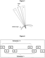
Figure 1 is a schematic drawing of the operation of the system. It can be seen that the target is only detected when the antenna beam is in the central position, whereas the sidelobe target is detected in all three antenna positions. By using data from the left hand (L) and right hand (R) beam positions the sidelobe detection can be eliminated when the beam is in the central position. -
Figure 2 is a schematic drawing showing independent sliding window M/N and azimuth centroiding processes that are used to resolve the ambiguities and estimate azimuth position for the left hand Σ (+) and right hand Σ (-) sequence of schedules. - In a system in accordance with one form of the invention, discussed above with reference to
Figure 1 , Σ channel data for a boresight of interest is compared with two sets of Σ channel data acting as 'G' channels, displaced in azimuth by, for example, ~ +/- 10 degrees from the boresight position. Detection lists from the two 'G' channels are then combined (OR-ed) together before being used to blank Σ channel detections. After SLB, range and Doppler ambiguities are removed by typical signal processing means that are well-known in the art. Further control of side lobe discretes can be exercised through intelligent application of range-variable thresholds once the absolute range has been established. - Note that the Σ channel data may be processed in different ways depending on whether it is to be used for Σ channel or 'G' channel purposes, for example it may be advantageous to employ lower thresholds for the 'G' channel.
- Two 'G' channels are proposed to improve the G - Σ ratio and exploit the fact that near-in side lobe levels are higher than far-out side lobe levels. Thus for a given position of side lobe discrete, with respect to the Σ channel boresight, there is likely to be a positive G - Σ ratio for one or other of the two 'G' patterns.
- It will be appreciated that separating the two 'G' patterns' by, for example, 20 degrees, will require a large number of coherent bursts of data to be held in memory. However this is unlikely to be an issue for modern digital processing systems.
- It will be appreciated that a number of considerations arise from this processing scheme as a result of data latency. For example, fixed frequency operation is assumed so that side lobe discretes do not become spatially decorrelated or migrate in Doppler bin number. Furthermore, as the data collected will effectively come from a 20 degree window, which corresponds to ~ 0.33 second at 60 degree / sec scan rate, some consideration needs to be given to range - Doppler migration over the period, which is not inconsiderable. For example, at 240 m/s target velocity, range migration lies within a -80m to +80m window for 360 degree scan excluding any effect of own ship motion.
- Moreover, large side lobe discretes can exhibit very angle-dependent patterns, with 'main beam' RCS lobes typically extending over only ~ 1 -2 milliradians. Over a period of 0.3 seconds or so there is a possibility of decorrelation as a result of own ship motion, particularly for short range discretes.
- Preferably, in another form of the invention, the challenge of range migration and time decorrelation can be overcome by exploiting the capabilities of an electronically scanned antenna.
- In this form of the invention the Σ and its associated 'G' channel is acquired on a burst by burst time multiplexed basis and synchronised with 'electronic' azimuth beam steps. Thus the equivalent time interval over which Σ and its associated 'G' data is obtained is now reduced to 2 bursts, effectively eliminating range migration and very significantly reducing the opportunity for decorrelation. This data pair effectively provides data simultaneously for two Σ beam patterns separated in angle, and for each Σ pattern the associated 'G' data is derived from the other Σ pattern of the data pair, e.g. the left hand Σ pattern is associated with the right Σ pattern acting as a G channel, whilst the right hand Σ pattern is associated with the left Σ hand pattern acting as a G channel.
- Preferably, the following points should also be considered.
- Firstly, the Σ antenna pattern at, say, ~ +/-10 degree electronic squint angle will have higher side lobes than when pointing at 0 degrees. This may be undesirable when a 0 degree Σ pattern is acting as 'G' for a +/- 10 degree squint Σ pattern. However, this effect may be reduced by avoiding the boresight position, and setting the Σ and 'G' position at, say, ~ +/- 5 degrees respectively.
- Secondly, it may be desirable to position the Σ and 'G' channels asymmetrically around the boresight pattern to ensure optimal coverage of the Σ side lobes by the 'G' channel.
- Finally, the scan rate, Σ beam width, schedule period, and angular position of the 'G' beam patterns are tightly connected. Nominally the scan rate will be chosen to ensure that the time on target (2-way Σ beam width / scan rate) is approximately equal to or slightly greater than the schedule period (the schedule comprising typically 8 bursts, each one at a unique PRF).
Claims (1)
- A radar system comprising a single channel antenna and receiver system and a side lobe blanking system, the radar system arranged to receive sum Σ channel data for each of a first, second and third bore sight positions; the second and third bore sight positions being displaced in azimuth in opposite directions from the first bore sight position; and characterised in that the side lobe blanking system arranged to:produce a combined data set for the first bore sight position by combining the Σ channel data from the second bore sight position and the Σ channel data from the third bore sight position; andcompare the combined data set with the Σ channel data from the first bore sight position to blank side lobe detections at the first bore sight position.
Applications Claiming Priority (2)
| Application Number | Priority Date | Filing Date | Title |
|---|---|---|---|
| GB1306030.6A GB2512619B (en) | 2013-04-03 | 2013-04-03 | Radar systems and methods |
| PCT/EP2014/056732 WO2014161957A1 (en) | 2013-04-03 | 2014-04-03 | Radar systems and methods |
Publications (3)
| Publication Number | Publication Date |
|---|---|
| EP2981840A1 EP2981840A1 (en) | 2016-02-10 |
| EP2981840B1 true EP2981840B1 (en) | 2025-06-04 |
| EP2981840C0 EP2981840C0 (en) | 2025-06-04 |
Family
ID=48483269
Family Applications (1)
| Application Number | Title | Priority Date | Filing Date |
|---|---|---|---|
| EP14714751.6A Active EP2981840B1 (en) | 2013-04-03 | 2014-04-03 | Radar systems and methods |
Country Status (5)
| Country | Link |
|---|---|
| US (1) | US10422855B2 (en) |
| EP (1) | EP2981840B1 (en) |
| GB (1) | GB2512619B (en) |
| IL (1) | IL241775B (en) |
| WO (1) | WO2014161957A1 (en) |
Families Citing this family (4)
| Publication number | Priority date | Publication date | Assignee | Title |
|---|---|---|---|---|
| US10976461B2 (en) * | 2017-10-17 | 2021-04-13 | California Institute Of Technology | Sub-surface imaging of dielectric structures and voids via narrowband electromagnetic resonance scattering |
| CN109073743A (en) * | 2017-12-18 | 2018-12-21 | 深圳市大疆创新科技有限公司 | Weak target detection method, microwave radar sensor and unmanned aerial vehicle |
| JP2021521432A (en) * | 2018-04-12 | 2021-08-26 | メタウェーブ コーポレーション | Methods and devices for object detection with built-in sidelobe features of metamaterial antennas |
| KR20220004830A (en) | 2019-06-03 | 2022-01-11 | 메타웨이브 코포레이션 | Guardband antenna of beam steering radar to improve resolution |
Family Cites Families (16)
| Publication number | Priority date | Publication date | Assignee | Title |
|---|---|---|---|---|
| US3202990A (en) * | 1959-05-04 | 1965-08-24 | Gen Electric | Intermediate frequency side-lobe canceller |
| US4023172A (en) * | 1959-12-17 | 1977-05-10 | Numax Electronics Incorporated | Monopulse system for cancellation of side lobe effects |
| US3623094A (en) * | 1969-02-27 | 1971-11-23 | Nasa | Target acquisition antenna |
| US5926128A (en) * | 1972-11-01 | 1999-07-20 | The Marconi Company Limited | Radar systems |
| US4088997A (en) * | 1977-02-28 | 1978-05-09 | General Dynamics Corporation | Single channel monopulse radar system |
| US4377811A (en) * | 1981-01-07 | 1983-03-22 | Westinghouse Electric Corp. | Medium PRF pulse doppler radar having simplified ground moving target rejection capabilities |
| US4646094A (en) * | 1983-08-04 | 1987-02-24 | The United States Of America As Represented By The Secretary Of The Air Force | Method of discriminating between signals |
| US4596986A (en) * | 1983-08-29 | 1986-06-24 | The United States Of America As Represented By The Secretary Of The Navy | Sidelobe canceller with adaptive antenna subarraying using a weighted Butler matrix |
| US4959653A (en) * | 1989-08-23 | 1990-09-25 | Massachusetts Institute Of Technology | Adaptive sidelobe blanker |
| US5739788A (en) * | 1996-12-03 | 1998-04-14 | The Aerospace Corporation | Adaptive receiving antenna for beam repositioning |
| US5907302A (en) * | 1997-12-19 | 1999-05-25 | The United States Of America As Represented By The Secretary Of The Air Force | Adaptive elevational scan processor statement of government interest |
| US6150976A (en) * | 1998-08-12 | 2000-11-21 | Aai Corporation | Synthesis of overlapping chirp waveforms |
| JP3675756B2 (en) * | 2001-11-30 | 2005-07-27 | 富士通テン株式会社 | Radar unnecessary peak detector |
| US8026839B2 (en) * | 2004-07-21 | 2011-09-27 | Daniel Alexander Weber | Selective-sampling receiver |
| EP1949133B1 (en) | 2005-11-16 | 2012-07-04 | Astrium Limited | Synthetic aperture radar |
| US20080068266A1 (en) | 2005-11-23 | 2008-03-20 | Northrop Grumman Corporation | Beamforming for spatial sidelobe cancellation and AMR direction finding |
-
2013
- 2013-04-03 GB GB1306030.6A patent/GB2512619B/en active Active
-
2014
- 2014-04-03 US US14/782,178 patent/US10422855B2/en active Active
- 2014-04-03 EP EP14714751.6A patent/EP2981840B1/en active Active
- 2014-04-03 WO PCT/EP2014/056732 patent/WO2014161957A1/en not_active Ceased
-
2015
- 2015-09-21 IL IL24177515A patent/IL241775B/en active IP Right Grant
Also Published As
| Publication number | Publication date |
|---|---|
| EP2981840C0 (en) | 2025-06-04 |
| EP2981840A1 (en) | 2016-02-10 |
| US20160041257A1 (en) | 2016-02-11 |
| US10422855B2 (en) | 2019-09-24 |
| WO2014161957A1 (en) | 2014-10-09 |
| IL241775B (en) | 2019-10-31 |
| GB201306030D0 (en) | 2013-05-22 |
| GB2512619A (en) | 2014-10-08 |
| IL241775A0 (en) | 2015-11-30 |
| GB2512619B (en) | 2018-11-14 |
Similar Documents
| Publication | Publication Date | Title |
|---|---|---|
| US9250317B1 (en) | Methods and apparatus for 3D radar data from 2D primary surveillance radar and passive adjunct radar | |
| Colone et al. | Sliding extensive cancellation algorithm for disturbance removal in passive radar | |
| AU2010209277B2 (en) | Low energy radar system | |
| Skolnik et al. | Senrad: An advanced wideband air-surveillance radar | |
| US20040257265A1 (en) | Radar antenna array | |
| CN108291959A (en) | Radar system with staggeredly serial transmission and parallel receive capabilities | |
| EP2834660B1 (en) | Radar surveillance system | |
| US10422855B2 (en) | Radar systems and methods | |
| US9097793B2 (en) | System for the detection of incoming munitions | |
| Hommes et al. | A fast tracking 60 GHz radar using a frequency scanning antenna | |
| US9201141B1 (en) | Multiple simultaneous transmit track beams using phase-only pattern synthesis | |
| US12265174B2 (en) | AESA TX pulse pair radiation pattern phase conjugation for low side lobe/maximum EIRP radiation pattern | |
| Chen et al. | A method against DRFM dense false target jamming based on jamming recognization | |
| EP2851647A1 (en) | Microwave system with enhanced capability to detect, identify and localize moving targets | |
| Fielding et al. | Waveform optimisation for efficient resource allocation in airborne AESA radar systems | |
| EP0351934A1 (en) | Radar system using electronically steerable active transmit-receive modules | |
| Blair et al. | Nnjpda for tracking closely spaced rayleigh targets with possibly merged measurements | |
| Grossi et al. | A search-and-revisit scanning policy to improve the detection rate in agile-beam radars | |
| JABBARIAN et al. | Target tracking in MIMO radar systems using velocity vector | |
| RU2638317C2 (en) | Method of pelengation of repeater jamming and radar installation for its implementation | |
| Sira et al. | Waveform-agile tracking in heavy sea clutter | |
| US20260050059A1 (en) | Operating method of a detection radar and associated detection radar | |
| US20240142574A1 (en) | Hybrid clutter suppression using electronically scanned antennas | |
| Buckley | Ambiguity suppression in a multiple beam radar | |
| Lei et al. | Space-time adaptive processing for sea clutter and jamming suppression in radar seekers |
Legal Events
| Date | Code | Title | Description |
|---|---|---|---|
| PUAI | Public reference made under article 153(3) epc to a published international application that has entered the european phase |
Free format text: ORIGINAL CODE: 0009012 |
|
| 17P | Request for examination filed |
Effective date: 20151019 |
|
| AK | Designated contracting states |
Kind code of ref document: A1 Designated state(s): AL AT BE BG CH CY CZ DE DK EE ES FI FR GB GR HR HU IE IS IT LI LT LU LV MC MK MT NL NO PL PT RO RS SE SI SK SM TR |
|
| AX | Request for extension of the european patent |
Extension state: BA ME |
|
| DAX | Request for extension of the european patent (deleted) | ||
| RAP1 | Party data changed (applicant data changed or rights of an application transferred) |
Owner name: LEONARDO MW LTD |
|
| STAA | Information on the status of an ep patent application or granted ep patent |
Free format text: STATUS: EXAMINATION IS IN PROGRESS |
|
| 17Q | First examination report despatched |
Effective date: 20191021 |
|
| RAP3 | Party data changed (applicant data changed or rights of an application transferred) |
Owner name: LEONARDO UK LTD |
|
| GRAP | Despatch of communication of intention to grant a patent |
Free format text: ORIGINAL CODE: EPIDOSNIGR1 |
|
| STAA | Information on the status of an ep patent application or granted ep patent |
Free format text: STATUS: GRANT OF PATENT IS INTENDED |
|
| INTG | Intention to grant announced |
Effective date: 20241029 |
|
| GRAS | Grant fee paid |
Free format text: ORIGINAL CODE: EPIDOSNIGR3 |
|
| GRAA | (expected) grant |
Free format text: ORIGINAL CODE: 0009210 |
|
| STAA | Information on the status of an ep patent application or granted ep patent |
Free format text: STATUS: THE PATENT HAS BEEN GRANTED |
|
| AK | Designated contracting states |
Kind code of ref document: B1 Designated state(s): AL AT BE BG CH CY CZ DE DK EE ES FI FR GB GR HR HU IE IS IT LI LT LU LV MC MK MT NL NO PL PT RO RS SE SI SK SM TR |
|
| REG | Reference to a national code |
Ref country code: GB Ref legal event code: FG4D |
|
| REG | Reference to a national code |
Ref country code: CH Ref legal event code: EP |
|
| REG | Reference to a national code |
Ref country code: DE Ref legal event code: R096 Ref document number: 602014092001 Country of ref document: DE |
|
| REG | Reference to a national code |
Ref country code: IE Ref legal event code: FG4D |
|
| U01 | Request for unitary effect filed |
Effective date: 20250702 |
|
| U07 | Unitary effect registered |
Designated state(s): AT BE BG DE DK EE FI FR IT LT LU LV MT NL PT RO SE SI Effective date: 20250710 |
|
| PG25 | Lapsed in a contracting state [announced via postgrant information from national office to epo] |
Ref country code: ES Free format text: LAPSE BECAUSE OF FAILURE TO SUBMIT A TRANSLATION OF THE DESCRIPTION OR TO PAY THE FEE WITHIN THE PRESCRIBED TIME-LIMIT Effective date: 20250604 |
|
| PG25 | Lapsed in a contracting state [announced via postgrant information from national office to epo] |
Ref country code: NO Free format text: LAPSE BECAUSE OF FAILURE TO SUBMIT A TRANSLATION OF THE DESCRIPTION OR TO PAY THE FEE WITHIN THE PRESCRIBED TIME-LIMIT Effective date: 20250904 Ref country code: GR Free format text: LAPSE BECAUSE OF FAILURE TO SUBMIT A TRANSLATION OF THE DESCRIPTION OR TO PAY THE FEE WITHIN THE PRESCRIBED TIME-LIMIT Effective date: 20250905 |
|
| PG25 | Lapsed in a contracting state [announced via postgrant information from national office to epo] |
Ref country code: PL Free format text: LAPSE BECAUSE OF FAILURE TO SUBMIT A TRANSLATION OF THE DESCRIPTION OR TO PAY THE FEE WITHIN THE PRESCRIBED TIME-LIMIT Effective date: 20250604 |
|
| PG25 | Lapsed in a contracting state [announced via postgrant information from national office to epo] |
Ref country code: HR Free format text: LAPSE BECAUSE OF FAILURE TO SUBMIT A TRANSLATION OF THE DESCRIPTION OR TO PAY THE FEE WITHIN THE PRESCRIBED TIME-LIMIT Effective date: 20250604 |
|
| PG25 | Lapsed in a contracting state [announced via postgrant information from national office to epo] |
Ref country code: RS Free format text: LAPSE BECAUSE OF FAILURE TO SUBMIT A TRANSLATION OF THE DESCRIPTION OR TO PAY THE FEE WITHIN THE PRESCRIBED TIME-LIMIT Effective date: 20250904 |
|
| PG25 | Lapsed in a contracting state [announced via postgrant information from national office to epo] |
Ref country code: IS Free format text: LAPSE BECAUSE OF FAILURE TO SUBMIT A TRANSLATION OF THE DESCRIPTION OR TO PAY THE FEE WITHIN THE PRESCRIBED TIME-LIMIT Effective date: 20251004 |
|
| PG25 | Lapsed in a contracting state [announced via postgrant information from national office to epo] |
Ref country code: SM Free format text: LAPSE BECAUSE OF FAILURE TO SUBMIT A TRANSLATION OF THE DESCRIPTION OR TO PAY THE FEE WITHIN THE PRESCRIBED TIME-LIMIT Effective date: 20250604 |
|
| PG25 | Lapsed in a contracting state [announced via postgrant information from national office to epo] |
Ref country code: CZ Free format text: LAPSE BECAUSE OF FAILURE TO SUBMIT A TRANSLATION OF THE DESCRIPTION OR TO PAY THE FEE WITHIN THE PRESCRIBED TIME-LIMIT Effective date: 20250604 |
|
| PG25 | Lapsed in a contracting state [announced via postgrant information from national office to epo] |
Ref country code: SK Free format text: LAPSE BECAUSE OF FAILURE TO SUBMIT A TRANSLATION OF THE DESCRIPTION OR TO PAY THE FEE WITHIN THE PRESCRIBED TIME-LIMIT Effective date: 20250604 |
|
| PGFP | Annual fee paid to national office [announced via postgrant information from national office to epo] |
Ref country code: GB Payment date: 20260312 Year of fee payment: 13 |
|
| PLBE | No opposition filed within time limit |
Free format text: ORIGINAL CODE: 0009261 |
|
| STAA | Information on the status of an ep patent application or granted ep patent |
Free format text: STATUS: NO OPPOSITION FILED WITHIN TIME LIMIT |
|
| REG | Reference to a national code |
Ref country code: CH Ref legal event code: L10 Free format text: ST27 STATUS EVENT CODE: U-0-0-L10-L00 (AS PROVIDED BY THE NATIONAL OFFICE) Effective date: 20260416 |
|
| 26N | No opposition filed |
Effective date: 20260305 |