EP2981813B1 - Helical computed tomography - Google Patents
Helical computed tomography Download PDFInfo
- Publication number
- EP2981813B1 EP2981813B1 EP14718310.7A EP14718310A EP2981813B1 EP 2981813 B1 EP2981813 B1 EP 2981813B1 EP 14718310 A EP14718310 A EP 14718310A EP 2981813 B1 EP2981813 B1 EP 2981813B1
- Authority
- EP
- European Patent Office
- Prior art keywords
- ray
- detector
- imaging system
- data acquisition
- radiographs
- Prior art date
- Legal status (The legal status is an assumption and is not a legal conclusion. Google has not performed a legal analysis and makes no representation as to the accuracy of the status listed.)
- Active
Links
Images






Classifications
-
- G—PHYSICS
- G01—MEASURING; TESTING
- G01N—INVESTIGATING OR ANALYSING MATERIALS BY DETERMINING THEIR CHEMICAL OR PHYSICAL PROPERTIES
- G01N23/00—Investigating or analysing materials by the use of wave or particle radiation, e.g. X-rays or neutrons, not covered by groups G01N3/00 – G01N17/00, G01N21/00 or G01N22/00
- G01N23/02—Investigating or analysing materials by the use of wave or particle radiation, e.g. X-rays or neutrons, not covered by groups G01N3/00 – G01N17/00, G01N21/00 or G01N22/00 by transmitting the radiation through the material
- G01N23/04—Investigating or analysing materials by the use of wave or particle radiation, e.g. X-rays or neutrons, not covered by groups G01N3/00 – G01N17/00, G01N21/00 or G01N22/00 by transmitting the radiation through the material and forming images of the material
- G01N23/046—Investigating or analysing materials by the use of wave or particle radiation, e.g. X-rays or neutrons, not covered by groups G01N3/00 – G01N17/00, G01N21/00 or G01N22/00 by transmitting the radiation through the material and forming images of the material using tomography, e.g. computed tomography [CT]
-
- A—HUMAN NECESSITIES
- A61—MEDICAL OR VETERINARY SCIENCE; HYGIENE
- A61B—DIAGNOSIS; SURGERY; IDENTIFICATION
- A61B6/00—Apparatus or devices for radiation diagnosis; Apparatus or devices for radiation diagnosis combined with radiation therapy equipment
- A61B6/02—Arrangements for diagnosis sequentially in different planes; Stereoscopic radiation diagnosis
- A61B6/03—Computed tomography [CT]
- A61B6/032—Transmission computed tomography [CT]
-
- A—HUMAN NECESSITIES
- A61—MEDICAL OR VETERINARY SCIENCE; HYGIENE
- A61B—DIAGNOSIS; SURGERY; IDENTIFICATION
- A61B6/00—Apparatus or devices for radiation diagnosis; Apparatus or devices for radiation diagnosis combined with radiation therapy equipment
- A61B6/52—Devices using data or image processing specially adapted for radiation diagnosis
-
- G—PHYSICS
- G01—MEASURING; TESTING
- G01V—GEOPHYSICS; GRAVITATIONAL MEASUREMENTS; DETECTING MASSES OR OBJECTS; TAGS
- G01V5/00—Prospecting or detecting by the use of ionising radiation, e.g. of natural or induced radioactivity
- G01V5/20—Detecting prohibited goods, e.g. weapons, explosives, hazardous substances, contraband or smuggled objects
- G01V5/22—Active interrogation, i.e. by irradiating objects or goods using external radiation sources, e.g. using gamma rays or cosmic rays
- G01V5/226—Active interrogation, i.e. by irradiating objects or goods using external radiation sources, e.g. using gamma rays or cosmic rays using tomography
-
- A—HUMAN NECESSITIES
- A61—MEDICAL OR VETERINARY SCIENCE; HYGIENE
- A61B—DIAGNOSIS; SURGERY; IDENTIFICATION
- A61B6/00—Apparatus or devices for radiation diagnosis; Apparatus or devices for radiation diagnosis combined with radiation therapy equipment
- A61B6/02—Arrangements for diagnosis sequentially in different planes; Stereoscopic radiation diagnosis
- A61B6/027—Arrangements for diagnosis sequentially in different planes; Stereoscopic radiation diagnosis characterised by the use of a particular data acquisition trajectory, e.g. helical or spiral
-
- A—HUMAN NECESSITIES
- A61—MEDICAL OR VETERINARY SCIENCE; HYGIENE
- A61B—DIAGNOSIS; SURGERY; IDENTIFICATION
- A61B6/00—Apparatus or devices for radiation diagnosis; Apparatus or devices for radiation diagnosis combined with radiation therapy equipment
- A61B6/40—Arrangements for generating radiation specially adapted for radiation diagnosis
- A61B6/4064—Arrangements for generating radiation specially adapted for radiation diagnosis specially adapted for producing a particular type of beam
- A61B6/4085—Cone-beams
-
- A—HUMAN NECESSITIES
- A61—MEDICAL OR VETERINARY SCIENCE; HYGIENE
- A61B—DIAGNOSIS; SURGERY; IDENTIFICATION
- A61B6/00—Apparatus or devices for radiation diagnosis; Apparatus or devices for radiation diagnosis combined with radiation therapy equipment
- A61B6/52—Devices using data or image processing specially adapted for radiation diagnosis
- A61B6/5205—Devices using data or image processing specially adapted for radiation diagnosis involving processing of raw data to produce diagnostic data
-
- A—HUMAN NECESSITIES
- A61—MEDICAL OR VETERINARY SCIENCE; HYGIENE
- A61B—DIAGNOSIS; SURGERY; IDENTIFICATION
- A61B6/00—Apparatus or devices for radiation diagnosis; Apparatus or devices for radiation diagnosis combined with radiation therapy equipment
- A61B6/52—Devices using data or image processing specially adapted for radiation diagnosis
- A61B6/5258—Devices using data or image processing specially adapted for radiation diagnosis involving detection or reduction of artifacts or noise
-
- G—PHYSICS
- G01—MEASURING; TESTING
- G01N—INVESTIGATING OR ANALYSING MATERIALS BY DETERMINING THEIR CHEMICAL OR PHYSICAL PROPERTIES
- G01N2223/00—Investigating materials by wave or particle radiation
- G01N2223/10—Different kinds of radiation or particles
- G01N2223/101—Different kinds of radiation or particles electromagnetic radiation
- G01N2223/1016—X-ray
-
- G—PHYSICS
- G01—MEASURING; TESTING
- G01N—INVESTIGATING OR ANALYSING MATERIALS BY DETERMINING THEIR CHEMICAL OR PHYSICAL PROPERTIES
- G01N2223/00—Investigating materials by wave or particle radiation
- G01N2223/30—Accessories, mechanical or electrical features
- G01N2223/33—Accessories, mechanical or electrical features scanning, i.e. relative motion for measurement of successive object-parts
- G01N2223/3307—Accessories, mechanical or electrical features scanning, i.e. relative motion for measurement of successive object-parts source and detector fixed; object moves
-
- G—PHYSICS
- G01—MEASURING; TESTING
- G01N—INVESTIGATING OR ANALYSING MATERIALS BY DETERMINING THEIR CHEMICAL OR PHYSICAL PROPERTIES
- G01N2223/00—Investigating materials by wave or particle radiation
- G01N2223/40—Imaging
- G01N2223/419—Imaging computed tomograph
Definitions
- This disclosure relates to computed tomography.
- X-ray computed tomography is a procedure that uses computer-processed x-rays to produce tomographic images of an object.
- a tomographic image of an object is an image of a conceptually two-dimensional "slice" of the object.
- a computing device may use the tomographic images of the object to generate a 3-dimensional image of the object.
- X-ray CT may be used for industrial purposes to conduct non-destructive evaluation of objects.
- the x-ray imaging system includes an x-ray generator, one or more radiation detectors, a rotary stage, a linear translation stage, a motion control system, and a data acquisition system.
- the x-ray generator may emit a fan-shaped or cone-shaped x-ray beam.
- the rotary stage has an axis of rotation arranged substantially perpendicular to an axis of the x-ray beam.
- the linear translation stage is configured to move the rotary stage linearly along an axis aligned with the axis of rotation of the rotary stage.
- the motion control system synchronizes rotational motion of the rotary stage and linear motion of the linear translation stage such that a point on a sample supported by the rotary stage traces out a spiral or helical pattern.
- the rotatory stage may move linearly along an axis while rotating around the same axis.
- the data acquisition system includes one or more processors configured to receive user input parameters. Based at least in part on the user input parameters, the one or more processors configure the x-ray imaging system to acquire radiographs. The one or more processors generate a three-dimensional image based at least in part on the radiographs.
- the present disclosure relates to a system according to claim 1 and a method according to claim 8.
- X-ray computed tomography is a commonly used technique of non-invasively or non-destructively obtaining three-dimensional structures in medical imaging and industrial non-destructive evaluation (NDE).
- CT X-ray computed tomography
- NDE non-destructive evaluation
- the techniques of this disclosure provide for an apparatus for obtaining the three-dimensional (3D) structure of objects (e.g. elongated objects) using an x-ray CT technique.
- the techniques of this disclosure also provide for instrumentation, a user control mechanism, and software algorithms of the apparatus.
- the apparatus may be used for NDE of naturally-occurring objects such as rock core samples, as well as manufactured components and systems.
- the apparatus may comprise an x-ray source, a radiation detector, and a rotary stage. The rotary stage may rotate samples so that radiographs can be obtained at different viewing angles.
- the x-ray source, the radiation detector, and the rotatory stage may each be mounted on linear positioning stages to place the x-ray source, the radiation detector, and the rotary stage in different geometric configurations.
- the system may provide a resolution ranging from 0.5 micrometers to 100 micrometers.
- FIG. 1 is a system diagram with both schematic elements and block elements illustrating an example instrumental setup, in accordance with one or more examples of this disclosure.
- an industrial CT system 10 comprises an x-ray source 12, a radiation detector 14, and a computing system 22.
- industrial CT system 10 may comprise one or more radiation detectors in addition to radiation detector 14.
- a sample may be mounted on a rotary stage 16.
- Example types of samples include machinery, rock cores, or other types of objects.
- an axis of rotation 17 of rotary stage 16 is perpendicular to the x-ray beam axis 19 (i.e., an axis of an x-ray beam 18 emitted by x-ray generator 12).
- industrial CT system 10 may acquire radiographs at different projection angles as the sample is rotated in x-ray beam 18.
- x-ray beam 18 is cone-shaped.
- x-ray beam 18 is fan-shaped.
- x-ray source 12 may provide x-rays with an energy range of 20 keV to 600 keV.
- industrial CT system 10 includes a vertical stage 20 that may move vertically.
- Rotary stage 16 is mounted or otherwise coupled to vertical stage 20 such that rotary stage 16 moves vertically when vertical stage 20 moves vertically.
- the motion of vertical stage 20 is be synchronized with the rotational motion of rotary stage 16 such that a point on a sample supported by rotary stage 16 and vertical stage 20 traces out a spiral or helical pattern.
- rotational stage 16 may be moved linearly in other directions.
- industrial CT system 10 may include a stage that moves rotary stage 16 in a direction other than vertical.
- industrial CT system 10 may comprise a linear translation stage having an axis of movement arranged along the axis of rotation of rotary stage 16. Movement of linear translation stage 20 along the axis of rotation 17 of rotary stage 16 results in movement of rotary stage 16 (as well as any sample mounted on rotary stage 16) along the axis of rotation 17 of rotary stage 16.
- Radiation detector 14 may comprise a flat panel x-ray detector (FPD) as shown in the example of FIG. 1 .
- radiation detector 14 may comprise a lens-coupled scintillation detector, a linear diode array (LDA), or another type of device that detects radiation.
- industrial CT system 10 may comprise one or more radiation detectors including at least one of: a flat-panel radiation detector, a lens-coupled high-resolution x-ray detector, and a linear diode array radiation detector.
- industrial CT system 10 comprises a computing system 22.
- Computing system 22 may comprise one or more computing devices, such as personal computers, laptop computers, server computers, mainframe computers, special-purpose computers, and so on.
- computing system 22 may be located remotely from other components of industrial CT system 10. For instance, computing system 22 may, from the perspective of users of the other components of industrial CT system 10, exist in "the cloud.”
- Computing system 22 may implement a motion control system 24 and a computer-controlled data acquisition system 26.
- Motion control system 24 may synchronize rotational motion of rotary stage 16 and linear motion of linear translation stage 20.
- motion control system 24 may be implemented separately form data acquisition system 24.
- Data acquisition system 26 receives input parameters from one or more users.
- data acquisition system 26 may receive indications (e.g., from input devices, such as keyboards, touchscreens, etc., or remote computing device) of user input of the input parameters.
- Data acquisition system 26 configures, based at least in part on the user input parameters, the x-ray imaging system to acquire radiographs.
- data acquisition system 26 acquires radiographs from radiation detector 14 (and/or other radiation detectors of industrial CT system 10), digitally record the radiographs, and process the radiographs.
- Data acquisition system 26 generates a three-dimensional image based at least in part on the radiographs. In this way, data acquisition system 26 may acquire radiographs, digitally record the radiographs, and reconstruct a 3-dimensional image from the radiographs.
- a sample under test may be rotated across a range of 180 degrees with radiographs acquired at specific intervals.
- the radiographs may then be mathematically assembled into 3D volume data representing the 3D structure of the sample under test.
- a disadvantage of this type of configuration may be the limited field of view, as only portions of the sample exposed to the x-ray beam cone can be examined. Hence, with elongated samples, only a partial volume can be imaged during each CT cycle.
- a series of multiple CT cycles must be performed independently on different portions of the sample, and the resulting series of 3D images must then be stitched numerically to obtain an image of the full structure.
- the techniques of this disclosure may overcome this limitation with the use of a motorized linear stage with its motion axis parallel to the sample's long axis.
- the linear stage e.g., linear translation stage 20
- the linear stage may continuously move the entire sample across the x-ray beam cone (e.g., x-ray beam 18) in a synchronized fashion to the rotation motion of rotary stage 16.
- a point on the sample may effectively trace out a spiral or helical pattern.
- spiral CT or helical CT an elongated sample can be scanned in a single cycle without the need of user intervention or additional numerical stitching.
- the techniques of this disclosure may present significant advantages over the conventional technique for a wide range of applications.
- Industrial CT system 10 may include a number of novel elements.
- industrial CT system 10 may include a novel instrumentation design, including novel detector designs incorporating detectors for a wide range of resolution and field of view combinations.
- industrial CT system 10 may use novel numerical algorithms for processing the radiographs and furthermore reconstructing a 3D image from the radiographs.
- a FPD may comprise a layer of scintillation material, such as Cesium Iodide, fabricated on an amorphous silicon on a glass detector array.
- the scintillator layer may absorb x-rays and may emit visible light photons that are, in turn, detected by a solid state detector.
- Pixel sizes of radiation detector 14 may range from tens to hundreds of micrometers.
- radiation detector 14 may include a FPD with a pixel size ranging from 25 micrometers to 300 micrometers.
- FPDs are currently the most commonly used detectors in industrial CT systems in a volumetric CT setup. FPDs generally provide 10-100 micrometer resolution in most applications, and fields of view from 10 mm to 400 mm. This design may be well-suited for objects with coarse features such as printed circuit boards and machined or cast components. Higher resolution can be achieved with the use of a lens-coupled detector system that uses lenses with various magnifications to achieve 0.5 micrometer to 10 micrometer resolution and 1 mm to 50 mm fields of view. This design may be well suited for objects with fine feature sizes such as integrated circuit components or cellular structures in biological systems. At the opposite size range, high-energy x-rays of greater than 300 keV may be used to penetrate large objects such as complete assembled machine systems. In these applications, LDA detectors are often used to reduce contrast reduction from scattered radiation.
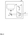
- FIG. 2 is a block diagram illustrating an example lens-coupled high-resolution x-ray detector 50, in accordance with one or more techniques of this disclosure.
- Radiation detector 14 of industrial CT system 10 may include lens-coupled high-resolution x-ray detector 50.
- Lens-coupled x-ray detector 50 may use an additional optical lens 52 to relay emitted visible light 54 to a detector 56, such as charge-coupled device (CCD) or complementary metal-oxide-semiconductor (CMOS) detector as shown in the example of FIG. 2 .
- a scintillator layer of radiation detector 14 may emit visible light 54 when the scintillator layer absorbs x-rays emitted by x-ray generator 12 or other x-ray source.
- Lens 52 may provide magnification in the range of 0.5x to 100x, thus making the effective pixel size of lens-coupled x-ray detector 50 between 0. 1 to 20 micrometers.
- lens-coupled x-ray detector 50 has a pixel size of 0.1 micrometers to 10 micrometers.
- a mirror 58 directs visible light 54 from lens 52 to detector 56.
- lens 52 is mounted in a rotary turret 60 that includes one or more additional lenses, such as lens 62. Turret 60 may be rotated or otherwise reconfigured such that emitted visible light 54 passes through lens 62 instead of lens 52.
- Lens 52 and lens 62 may have different focal lengths and hence may be used to achieve different resolutions and/or fields of view.
- lens 52 may be a wide-field lens and lens 62 may be a high-resolution lens.
- industrial CT system 10 of this disclosure may combine two or more of these three types of detector technologies.
- industrial CT system 10 may comprise a combined FDP and lens-coupled detector system to produce a multi-scale imaging system capable of both system-scale NDE with complete assemblies as well as detailed examination at a sub-micrometer scale.
- industrial CT system 10 may comprise a lens-coupled high-resolution detector with a pixel size in a range of 0.1 micrometers to 10 micrometers, and a flat-panel detector with a pixel size ranging from 25 micrometers to 300 micrometers.
- industrial CT system 10 may include a mechanical mechanism to switch between at least the lens-coupled high-resolution x-ray detector and the flat-panel detector.
- the use of spiral-CT may further provide extended scanning length with this resolution and field of view combination for elongated objects, such as full rock core samples or missiles.
- FIGS. 3A-3F are diagrams illustrating example user control interfaces for spiral-CT, in accordance with one or more techniques of this disclosure.
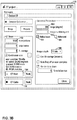
- FIG. 3A is a diagram illustrating an example system parameter setup interface 100.
- FIG. 3B is a diagram illustrating an example conventional (i.e., non-spiral) CT scan setup interface 150.
- FIG. 3C is a diagram illustrating another example conventional (i.e., non-spiral) CT scan setup interface, in accordance with one or more techniques of this disclosure.
- FIG. 3D is a diagram illustrating an example spiral CT scan setup interface 200.
- FIG. 3E is a diagram illustrating another example spiral CT scan setup interface, in accordance with one or more techniques of this disclosure.
- FIG. 3F is a diagram illustrating an example image preview interface 250. Particularly, image preview interface 250 illustrates an emulation environment.
- System parameter setup interface 100 of FIG. 3A includes user interface (UI) elements for controlling industrial CT system 10.
- the UI elements of industrial CT system 10 may enable data acquisition system 26 to receive user input of parameters common to both spiral CT and non-spiral CT.
- system parameter setup interface 100 includes a UI element 102 for controlling table rotation (i.e., rotary stage 16), a UI element 104 for controlling a position of an x-ray source (e.g., x-ray generator 12), a UI element 106 for controlling a position of radiation detector 14, a UI element 108 for controlling a table magnification (e.g., a position of rotary stage 16 relative to x-ray generator 12 and radiation detector 14), and a UI element 110 for controlling a magnification level of radiation detector 14.
- system parameter setup interface 100 includes a set of UI elements 112 for controlling whether motion axis that are unused during a CT scan should be disabled, e.g. 108 and 110.
- the home UI element within system parameter setup interface 100 may drive the table rotation to a fixed reference position.
- the reset UI element within system parameter setup interface 100 sets the current table rotation angle to zero.
- Conventional CT scan setup interface 150 of FIG. 3B may include UI elements for configuring industrial CT system 10 to perform a non-spiral CT scan.
- conventional CT scan setup interface 150 may include a field 152 for entry of the number of projections to be captured during a CT scan.
- Conventional CT scan setup interface 150 may also include a UI element to skip frames (projections) to synchronize a desired x-ray detector acquisition rate with a table rotation rate that mitigates motion blur. A number of frames may be averaged together into a single projection to reduce noise using the "fr. average" UI element.
- conventional CT scan setup interface 150 may include a button 154 to initiate a CT scan and another button 156 to initiate a calibration process for industrial CT system 10.
- conventional CT scan setup interface 150 includes a dropdown box 158 to control the bit depth of pixels of radiographs acquired in the CT scan.
- Conventional CT scan setup interface 150 also includes a textbox 160 for entry of a degree range through which rotary stage 16 rotates during the CT scan. The degree range may be greater than or equal to 0. In some instances, the degree range may be greater than 360 degrees.
- conventional CT scan setup interface 150 includes a textbox 162 for entry of a number from data acquisition system 28 starts numbering radiographs acquired during the CT scan. The numbering of the radiographs may be used for subsequent reference to individual radiographs acquired during the CT scan.
- Conventional CT scan setup interface 150 may also provide UI elements to acquire (snap) a screenshot at the current position of the imaging system or record a series of screenshots (video) of the imaging window over a period of time.
- FIG. 3C is a diagram illustrating another example conventional (i.e., non-spiral) CT scan setup interface 170, in accordance with one or more techniques of this disclosure.
- the helical scan setup interface within FIG. 3C may be displayed by selecting the checkbox 172, labeled "VorteX.”
- the user may enter the range of linear travel in the "scan height" input field.
- the type of scan may be selected using a "scan setup" drop down element 176.
- Options in the scan setup drop down element 176 may include fast, medium, or precise, which reflect a scan duration-to-quality tradeoff.
- the scan setup selection may combine with the scan height to automatically choose other scan-dependent parameters.
- data acquisition system 28 may receive indications of user input of the scanning parameters.
- Data acquisition system 28 may output scan setup interface 200 of FIG. 3D for display in response to receiving an indication of user input to select a helical scan checkbox 154 and/or an advanced checkbox 156 in conventional CT scan setup interface 150 or checkbox 172 and/or an advanced checkbox 178 in conventional CT scan setup interface 170.
- the user may enter a small number of scanning parameters, such as a scan range of the linear stage (i.e., linear scan range) and optionally the range of linear travel through each spiral revolution and the number of revolutions, in the advanced menu.
- the linear scan range parameter is indicated as "part height" in the example of FIG. 3D .
- data acquisition system 28 may receive indications of user input of the scanning parameters.
- Computing system 22 may execute a data acquisition control program to automatically optimize key image acquisition parameters (such as total number of projection, angular spacing, the relative rate of linear and rotation motion) based on these user inputs and other geometric parameters such as the x-ray source spot size, detector pixel size, magnification, etc.
- the image acquisition parameters may also be referred to herein as "data acquisition parameters.” This optimization may be performed with a set of proprietary mathematical algorithms that, for example, calculate the necessary number of projections to prevent under-sampling artefacts and accommodate the user's time budget for acquisition.
- the computing device may use one or more algorithms to determine, based at least in part on the linear scan range, one or more additional data acquisition parameters and may configure, based at least in part on the one or more additional data acquisition parameters, the x-ray imaging system to acquire the radiographs.
- data acquisition system 26 may accept user input parameters, the user input parameters consisting of a linear scan range and duration-to-quality scan setup only.
- data acquisition system 26 uses algorithms to determine additional data acquisition parameters, such as the number of projections, frames to skip, helical pitch and number of revolutions.
- spiral CT input is more complex and some key input parameters may be less intuitive than conventional CT setups, having such an optimization system to reduce the user's effort may be helpful to making this technique practical, particularly for a multi-scale x-ray imaging system spanning a wide resolution and field of view range.
- data acquisition system 28 may receive an indication of user input of a part height in field 202.
- the part height may indicate a height (or length) of a part (e.g., sample) under test.
- data acquisition system 28 may calculate, based at least in part on the part height, other values shown in spiral CT scan setup interface 200, such as a helical pitch, a number of helical sets, a number of revolutions per set, a number of projections per revolution, height difference per projection, angle difference per projection, a set scale indicating the filtered weight to apply per helical set, total height difference in the CT scan, total number of degrees rotated in the CT scan, the total number of revolutions of the sample during the CT scan, and the total number of projections (e.g., radiographs) acquired during the CT scan.
- a helical pitch such as a number of helical sets, a number of revolutions per set, a number of projections per revolution, height difference per projection, angle difference per projection, a set scale indicating
- Data acquisition system 28 may receive indications of user input of the helical set height and a number of revolutions during the CT scan and may cause data acquisition system 28 to update its parameter calculations.
- a helical set comprises a number of consecutive revolutions in the helix whose projected radiographs have, for example,50% overlap vertically.
- the helical set height is the vertical extent of a helical set.
- data acquisition system 28 may receive indications of user input of the scanning parameters.
- Data acquisition system 28 may use values entered in conventional CT scan setup interface 150 in addition to values entered in spiral CT scan setup interface 200 to calculate the scan summary parameters shown in FIG. 3D . In this way, the user does not need to manually calculate or input these parameters; rather the scan summary parameters are computed, such as total projections from the scan height and height per projection.
- FIG. 3E is a diagram illustrating another example spiral CT scan setup interface 230, in accordance with one or more techniques of this disclosure.
- Spiral CT scan setup interface 230 is similar in some respects to spiral CT scan setup interface 200 of FIG. 3D , but includes a number of different features.
- Data acquisition system 28 may output scan setup interface 200 of FIG. 3E for display in response to receiving an indication of user input to select a helical scan advanced checkbox 166 in conventional CT scan setup interface 150 or checkbox 172 and/or an advanced checkbox 178 in conventional CT scan setup interface 170.
- the user may enter a small number of scanning parameters, such as a scan range of the linear stage (i.e., linear scan range), a helical set height 236, and a number of revolutions 238, in the advanced dialog.
- the linear scan range parameter is indicated as a "scan height" element 232 in the example of FIG. 3E .
- data acquisition system 28 may calculate, based at least in part on the scan height, helical pitch, helical set height, and/or number of revolutions, a number of helical sets, a number of revolutions per set, a number of projections per revolution, a height difference per projection, an angle difference per projection, a total height difference in the CT scan, a total number of degrees rotated in the CT scan, a total number of revolutions of the sample during the CT scan, and a total number of projections (e.g., radiographs) acquired during the CT scan.
- a total number of projections e.g., radiographs
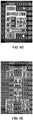
- FIGS. 4A-4E illustrate example images of a test structure scanned using a spiral-CT technique and a conventional CT technique, in accordance with one or more techniques of this disclosure.
- the data was acquired using the parameters optimized with an algorithm as described above.
- the conventional CT image shows only a small region of the entire structure. In order to obtain the complete structure, a number of such scans may be performed and numerically stitched in post-processing.
- the spiral-CT image was acquired in a single cycle.
- the spiral-CT data also shows better contrast and resolution with fewer artifacts than conventional CT.
- FIG. 4A is a diagram illustrating a volume rendering of an example 3-dimensional structure obtained using spiral-CT.
- FIG. 4B is a diagram illustrating a first example cross-sectional image of the 3-dimensional structure of FIG. 4A.
- FIG. 4C is a diagram illustrating a second example cross-sectional image of the 3-dimensional structure of FIG. 4A .
- FIG. 4D is a diagram illustrating a third example cross-sectional image of the 3-dimensional structure of FIG. 4A .
- the 3D structure obtained using spiral-CT is shown in FIG. 4A as a volume rendering, and its cross-sectional images are shown in FIGS. 4B, 4C , and 4D along the three axes.
- FIG. 4E is a diagram illustrating an example cross-sectional image of the 3-dimensional structure of FIG. 4A .
- the result from conventional volumetric CT is shown in FIG. 4E .
- the artifacts in conventional CT images are most prominent at the top and bottom of reconstruction area shown in FIG. 4E where the images are exposed to x-rays at high cone angles.
- Such artifacts may be particularly common for structures containing primarily flat structures aligned perpendicular to the rotation axis. Whereas these exposure angles are fixed during a conventional CT scan, they may vary in a spiral scan sequence as linear translation stage 20 translates.
- one or more processors of data acquisition system 26 ( FIG. 1 ) are configured to perform digital filtering calculations with acquired radiographs to reduce artifacts associated with particular cone angles (e.g., high cone angles) of the x-ray beam.
- the one or more processors of data acquisition system 26 is configured to perform digital filtering calculations including a Gaussian-type digital filter with acquired radiographs.
- FIG. 5 is a conceptual illustration of a weighted back-projection functional construction, in accordance with the invention.
- FIG. 6 is a flowchart illustrating an example operation of an industrial CT system, in accordance with one or more techniques of this disclosure. The example operation of FIG. 6 is explained with reference to the example system of FIG. 1 . However, the technique shown in FIG. 6 is not necessarily limited to use in the system of FIG. 1 and may be used in other systems.
- a data acquisition system may receive user input parameters (300).
- the data acquisition system may receive an indication of user input of the user input parameters.
- the data acquisition system may receive user input of a linear scan range.
- the linear scan range may be a range of linear motion of a linear translation stage (e.g., linear translation stage 20).
- the data acquisition system may use one or more algorithms to determine, based at least in part on the linear scan range, one or more additional data acquisition parameters.
- the data acquisition system may configure, based at least in part on the user input parameters, an x-ray imaging system (e.g., industrial CT system 10) to acquire radiographs (302).
- an x-ray imaging system may comprise an x-ray generator (e.g., x-ray generator 12), one or more radiation detectors (e.g., radiation detector 14), a rotary stage (e.g., rotary stage 16) having an axis of rotation arranged perpendicular to an axis of x-ray beam emitted by the x-ray generator, and a linear translation stage having an axis arranged along the axis of rotation of the rotary stage.
- an x-ray imaging system may comprise an x-ray generator (e.g., x-ray generator 12), one or more radiation detectors (e.g., radiation detector 14), a rotary stage (e.g., rotary stage 16) having an axis of rotation arranged perpendicular to an axis of x-ray beam
- the x-ray imaging system may comprise a motion control system (e.g., motion control system 24) that synchronizes rotational motion of the rotary stage and linear motion of the linear translation stage.
- the data acquisition system may generate a three-dimensional image based at least in part on the radiographs (304).
- Computer-readable media may include computer-readable storage media, which corresponds to a tangible medium such as data storage media, or communication media including any medium that facilitates transfer of a computer program from one place to another, e.g., according to a communication protocol.
- computer-readable media generally may correspond to (1) tangible computer-readable storage media which is non-transitory or (2) a communication medium such as a signal or carrier wave.
- Data storage media may be any available media that can be accessed by one or more computers or one or more processors to retrieve instructions, code and/or data structures for implementation of the techniques described in this disclosure.
- a computer program product may include a computer-readable medium.
- such computer-readable storage media can comprise RAM, ROM, EEPROM, CD-ROM or other optical disk storage, magnetic disk storage, or other magnetic storage devices, flash memory, or any other medium that can be used to store desired program code in the form of instructions or data structures and that can be accessed by a computer.
- any connection is properly termed a computer-readable medium.
- a computer-readable medium For example, if instructions are transmitted from a website, server, or other remote source using a coaxial cable, fiber optic cable, twisted pair, digital subscriber line (DSL), or wireless technologies such as infrared, radio, and microwave, then the coaxial cable, fiber optic cable, twisted pair, DSL, or wireless technologies such as infrared, radio, and microwave are included in the definition of medium.
- DSL digital subscriber line
- Disk and disc includes compact disc (CD), laser disc, optical disc, digital versatile disc (DVD), floppy disk and Blu-ray disc, where disks usually reproduce data magnetically, while discs reproduce data optically with lasers. Combinations of the above should also be included within the scope of computer-readable media.
- processors such as one or more digital signal processors (DSPs), general purpose microprocessors, application specific integrated circuits (ASICs), field programmable logic arrays (FPGAs), or other equivalent integrated or discrete logic circuitry.
- DSPs digital signal processors
- ASICs application specific integrated circuits
- FPGAs field programmable logic arrays
- processors may refer to any of the foregoing structure or any other structure suitable for implementation of the techniques described herein.
- the functionality described herein may be provided within dedicated hardware and/or software modules. Also, particular portions of the techniques may be implemented in one or more circuits or logic elements.
Landscapes
- Health & Medical Sciences (AREA)
- Life Sciences & Earth Sciences (AREA)
- Engineering & Computer Science (AREA)
- Physics & Mathematics (AREA)
- Nuclear Medicine, Radiotherapy & Molecular Imaging (AREA)
- General Health & Medical Sciences (AREA)
- Radiology & Medical Imaging (AREA)
- Pathology (AREA)
- Medical Informatics (AREA)
- Theoretical Computer Science (AREA)
- General Physics & Mathematics (AREA)
- Pulmonology (AREA)
- High Energy & Nuclear Physics (AREA)
- Chemical & Material Sciences (AREA)
- Analytical Chemistry (AREA)
- Immunology (AREA)
- Biochemistry (AREA)
- Surgery (AREA)
- Public Health (AREA)
- Biomedical Technology (AREA)
- Heart & Thoracic Surgery (AREA)
- Molecular Biology (AREA)
- Biophysics (AREA)
- Animal Behavior & Ethology (AREA)
- Optics & Photonics (AREA)
- Veterinary Medicine (AREA)
- Computer Vision & Pattern Recognition (AREA)
- General Life Sciences & Earth Sciences (AREA)
- Geophysics (AREA)
- Analysing Materials By The Use Of Radiation (AREA)
- Apparatus For Radiation Diagnosis (AREA)
- Quality & Reliability (AREA)
Description
- This application claims the benefit of
U.S. Provisional Patent Application No. 61/808,424 - This disclosure relates to computed tomography.
- X-ray computed tomography (CT) is a procedure that uses computer-processed x-rays to produce tomographic images of an object. A tomographic image of an object is an image of a conceptually two-dimensional "slice" of the object. A computing device may use the tomographic images of the object to generate a 3-dimensional image of the object. X-ray CT may be used for industrial purposes to conduct non-destructive evaluation of objects.
- In general, this disclosure describes an x-ray imaging system for helical (i.e., spiral) computed tomography (CT). The x-ray imaging system includes an x-ray generator, one or more radiation detectors, a rotary stage, a linear translation stage, a motion control system, and a data acquisition system. The x-ray generator may emit a fan-shaped or cone-shaped x-ray beam. The rotary stage has an axis of rotation arranged substantially perpendicular to an axis of the x-ray beam. The linear translation stage is configured to move the rotary stage linearly along an axis aligned with the axis of rotation of the rotary stage. The motion control system synchronizes rotational motion of the rotary stage and linear motion of the linear translation stage such that a point on a sample supported by the rotary stage traces out a spiral or helical pattern. Thus, the rotatory stage may move linearly along an axis while rotating around the same axis. The data acquisition system includes one or more processors configured to receive user input parameters. Based at least in part on the user input parameters, the one or more processors configure the x-ray imaging system to acquire radiographs. The one or more processors generate a three-dimensional image based at least in part on the radiographs. In particular, the present disclosure relates to a system according to
claim 1 and a method according toclaim 8. - The details of one or more examples are set forth in the accompanying drawings and the description below. Other features, objects, and advantages will be apparent from the description, drawings, and from the claims.
-
-
FIG. 1 is a system diagram with both schematic elements and block element, illustrating an example instrumental setup in accordance with one or more examples of this disclosure. -
FIG. 2 is a block diagram illustrating an example lens-coupled high-resolution x-ray detector, in accordance with one or more techniques of this disclosure. -
FIG. 3A is a diagram illustrating an example system parameter setup interface, in accordance with one or more techniques of this disclosure. -
FIG. 3B is a diagram illustrating an example conventional (i.e., non-spiral) computed tomography (CT) scan setup interface, in accordance with one or more techniques of this disclosure. -
FIG. 3C is a diagram illustrating another example conventional (i.e., non-spiral) CT scan setup interface, in accordance with one or more techniques of this disclosure. -
FIG. 3D is a diagram illustrating an example spiral CT scan setup interface, in accordance with one or more techniques of this disclosure. -
FIG. 3E is a diagram illustrating another example spiral CT scan setup interface, in accordance with one or more techniques of this disclosure. -
FIG. 3F is a diagram illustrating an example image preview interface, in accordance with one or more techniques of this disclosure. -
FIG. 4A is a diagram illustrating a volume rendering of an example 3-dimensional structure obtained using spiral-CT. -
FIG. 4B is a diagram illustrating a first example cross-sectional image of the 3-dimensional structure ofFIG. 4A . -
FIG. 4C is a diagram illustrating a second example cross-sectional image of the 3-dimensional structure ofFIG. 4A . -
FIG. 4D is a diagram illustrating a third example cross-sectional image of the 3-dimensional structure ofFIG. 4A . -
FIG. 4E is a diagram illustrating an example cross-sectional image of the 3-dimensional structure ofFIG. 4A . -
FIG. 5 is a conceptual illustration of a weighted back-projection functional construction, in accordance with one or more techniques of this disclosure. -
FIG. 6 is a flowchart illustrating an example operation of an industrial CT system, in accordance with one or more techniques of this disclosure. - X-ray computed tomography (CT) is a commonly used technique of non-invasively or non-destructively obtaining three-dimensional structures in medical imaging and industrial non-destructive evaluation (NDE). The techniques of this disclosure provide for an apparatus for obtaining the three-dimensional (3D) structure of objects (e.g. elongated objects) using an x-ray CT technique. The techniques of this disclosure also provide for instrumentation, a user control mechanism, and software algorithms of the apparatus. The apparatus may be used for NDE of naturally-occurring objects such as rock core samples, as well as manufactured components and systems. The apparatus may comprise an x-ray source, a radiation detector, and a rotary stage. The rotary stage may rotate samples so that radiographs can be obtained at different viewing angles. The x-ray source, the radiation detector, and the rotatory stage may each be mounted on linear positioning stages to place the x-ray source, the radiation detector, and the rotary stage in different geometric configurations. In one example configuration described in this disclosure, the system may provide a resolution ranging from 0.5 micrometers to 100 micrometers.
-
FIG. 1 is a system diagram with both schematic elements and block elements illustrating an example instrumental setup, in accordance with one or more examples of this disclosure. As shown in the example ofFIG. 1 , anindustrial CT system 10 comprises anx-ray source 12, aradiation detector 14, and a computing system 22. Although not shown in the example ofFIG. 1 ,industrial CT system 10 may comprise one or more radiation detectors in addition toradiation detector 14. - A sample may be mounted on a rotary stage 16. Example types of samples include machinery, rock cores, or other types of objects. In typical examples, an axis of
rotation 17 of rotary stage 16 is perpendicular to the x-ray beam axis 19 (i.e., an axis of anx-ray beam 18 emitted by x-ray generator 12). Accordingly,industrial CT system 10 may acquire radiographs at different projection angles as the sample is rotated inx-ray beam 18. In the example ofFIG. 1 ,x-ray beam 18 is cone-shaped. In other examples,x-ray beam 18 is fan-shaped. In some examples,x-ray source 12 may provide x-rays with an energy range of 20 keV to 600 keV. - Furthermore,
industrial CT system 10 includes avertical stage 20 that may move vertically. Rotary stage 16 is mounted or otherwise coupled tovertical stage 20 such that rotary stage 16 moves vertically whenvertical stage 20 moves vertically. The motion ofvertical stage 20 is be synchronized with the rotational motion of rotary stage 16 such that a point on a sample supported by rotary stage 16 andvertical stage 20 traces out a spiral or helical pattern. In other examples, rotational stage 16 may be moved linearly in other directions. For instance,industrial CT system 10 may include a stage that moves rotary stage 16 in a direction other than vertical. Accordingly, this disclosure may refer tovertical stage 20 as "linear translation stage 20." In this way,industrial CT system 10 may comprise a linear translation stage having an axis of movement arranged along the axis of rotation of rotary stage 16. Movement oflinear translation stage 20 along the axis ofrotation 17 of rotary stage 16 results in movement of rotary stage 16 (as well as any sample mounted on rotary stage 16) along the axis ofrotation 17 of rotary stage 16. -
Radiation detector 14 may comprise a flat panel x-ray detector (FPD) as shown in the example ofFIG. 1 . In other examples,radiation detector 14 may comprise a lens-coupled scintillation detector, a linear diode array (LDA), or another type of device that detects radiation. Thus,industrial CT system 10 may comprise one or more radiation detectors including at least one of: a flat-panel radiation detector, a lens-coupled high-resolution x-ray detector, and a linear diode array radiation detector. - Furthermore, in the example of
FIG. 1 ,industrial CT system 10 comprises a computing system 22. Computing system 22 may comprise one or more computing devices, such as personal computers, laptop computers, server computers, mainframe computers, special-purpose computers, and so on. In some examples, computing system 22 may be located remotely from other components ofindustrial CT system 10. For instance, computing system 22 may, from the perspective of users of the other components ofindustrial CT system 10, exist in "the cloud." - Computing system 22 may implement a
motion control system 24 and a computer-controlleddata acquisition system 26.Motion control system 24 may synchronize rotational motion of rotary stage 16 and linear motion oflinear translation stage 20. In other examples,motion control system 24 may be implemented separately formdata acquisition system 24. -
Data acquisition system 26 receives input parameters from one or more users. In some examples,data acquisition system 26 may receive indications (e.g., from input devices, such as keyboards, touchscreens, etc., or remote computing device) of user input of the input parameters.Data acquisition system 26 configures, based at least in part on the user input parameters, the x-ray imaging system to acquire radiographs. Furthermore,data acquisition system 26 acquires radiographs from radiation detector 14 (and/or other radiation detectors of industrial CT system 10), digitally record the radiographs, and process the radiographs.Data acquisition system 26 generates a three-dimensional image based at least in part on the radiographs. In this way,data acquisition system 26 may acquire radiographs, digitally record the radiographs, and reconstruct a 3-dimensional image from the radiographs. - In an example CT cycle, a sample under test may be rotated across a range of 180 degrees with radiographs acquired at specific intervals. The radiographs may then be mathematically assembled into 3D volume data representing the 3D structure of the sample under test. A disadvantage of this type of configuration may be the limited field of view, as only portions of the sample exposed to the x-ray beam cone can be examined. Hence, with elongated samples, only a partial volume can be imaged during each CT cycle. In order to image the complete sample, a series of multiple CT cycles must be performed independently on different portions of the sample, and the resulting series of 3D images must then be stitched numerically to obtain an image of the full structure.
- The techniques of this disclosure may overcome this limitation with the use of a motorized linear stage with its motion axis parallel to the sample's long axis. During a CT scan, the linear stage (e.g., linear translation stage 20) may continuously move the entire sample across the x-ray beam cone (e.g., x-ray beam 18) in a synchronized fashion to the rotation motion of rotary stage 16. With this additional motion, a point on the sample may effectively trace out a spiral or helical pattern. Hence, this approach may be referred to herein as spiral CT or helical CT. Using this technique, an elongated sample can be scanned in a single cycle without the need of user intervention or additional numerical stitching. The techniques of this disclosure may present significant advantages over the conventional technique for a wide range of applications.
- The techniques of this disclosure may apply primarily to industrial CT systems focusing on high-resolution applications.
Industrial CT system 10 may include a number of novel elements. For example,industrial CT system 10 may include a novel instrumentation design, including novel detector designs incorporating detectors for a wide range of resolution and field of view combinations. In another example,industrial CT system 10 may use novel numerical algorithms for processing the radiographs and furthermore reconstructing a 3D image from the radiographs. - A FPD may comprise a layer of scintillation material, such as Cesium Iodide, fabricated on an amorphous silicon on a glass detector array. The scintillator layer may absorb x-rays and may emit visible light photons that are, in turn, detected by a solid state detector. Pixel sizes of
radiation detector 14 may range from tens to hundreds of micrometers. For instance,radiation detector 14 may include a FPD with a pixel size ranging from 25 micrometers to 300 micrometers. - FPDs are currently the most commonly used detectors in industrial CT systems in a volumetric CT setup. FPDs generally provide 10-100 micrometer resolution in most applications, and fields of view from 10 mm to 400 mm. This design may be well-suited for objects with coarse features such as printed circuit boards and machined or cast components. Higher resolution can be achieved with the use of a lens-coupled detector system that uses lenses with various magnifications to achieve 0.5 micrometer to 10 micrometer resolution and 1 mm to 50 mm fields of view. This design may be well suited for objects with fine feature sizes such as integrated circuit components or cellular structures in biological systems. At the opposite size range, high-energy x-rays of greater than 300 keV may be used to penetrate large objects such as complete assembled machine systems. In these applications, LDA detectors are often used to reduce contrast reduction from scattered radiation.
-
FIG. 2 is a block diagram illustrating an example lens-coupled high-resolution x-ray detector 50, in accordance with one or more techniques of this disclosure.Radiation detector 14 ofindustrial CT system 10 may include lens-coupled high-resolution x-ray detector 50. Lens-coupledx-ray detector 50 may use an additionaloptical lens 52 to relay emittedvisible light 54 to adetector 56, such as charge-coupled device (CCD) or complementary metal-oxide-semiconductor (CMOS) detector as shown in the example ofFIG. 2 . A scintillator layer ofradiation detector 14 may emitvisible light 54 when the scintillator layer absorbs x-rays emitted byx-ray generator 12 or other x-ray source. -
Lens 52 may provide magnification in the range of 0.5x to 100x, thus making the effective pixel size of lens-coupledx-ray detector 50 between 0. 1 to 20 micrometers. In some examples, lens-coupledx-ray detector 50 has a pixel size of 0.1 micrometers to 10 micrometers. In the example ofFIG. 2 , amirror 58 directs visible light 54 fromlens 52 todetector 56. Furthermore, in the example ofFIG. 2 ,lens 52 is mounted in arotary turret 60 that includes one or more additional lenses, such aslens 62.Turret 60 may be rotated or otherwise reconfigured such that emitted visible light 54 passes throughlens 62 instead oflens 52.Lens 52 andlens 62 may have different focal lengths and hence may be used to achieve different resolutions and/or fields of view. For instance,lens 52 may be a wide-field lens andlens 62 may be a high-resolution lens. - To further mitigate the field of view and resolution limitations of each detector technology (i.e., FPD technology, lens-coupled high-resolution x-ray detector technology, and LDA technology),
industrial CT system 10 of this disclosure may combine two or more of these three types of detector technologies. For example,industrial CT system 10 may comprise a combined FDP and lens-coupled detector system to produce a multi-scale imaging system capable of both system-scale NDE with complete assemblies as well as detailed examination at a sub-micrometer scale. For instance,industrial CT system 10 may comprise a lens-coupled high-resolution detector with a pixel size in a range of 0.1 micrometers to 10 micrometers, and a flat-panel detector with a pixel size ranging from 25 micrometers to 300 micrometers. In this example,industrial CT system 10 may include a mechanical mechanism to switch between at least the lens-coupled high-resolution x-ray detector and the flat-panel detector. The use of spiral-CT may further provide extended scanning length with this resolution and field of view combination for elongated objects, such as full rock core samples or missiles. -
FIGS. 3A-3F are diagrams illustrating example user control interfaces for spiral-CT, in accordance with one or more techniques of this disclosure. In particular,FIG. 3A is a diagram illustrating an example systemparameter setup interface 100.FIG. 3B is a diagram illustrating an example conventional (i.e., non-spiral) CTscan setup interface 150.FIG. 3C is a diagram illustrating another example conventional (i.e., non-spiral) CT scan setup interface, in accordance with one or more techniques of this disclosure.FIG. 3D is a diagram illustrating an example spiral CTscan setup interface 200.FIG. 3E is a diagram illustrating another example spiral CT scan setup interface, in accordance with one or more techniques of this disclosure.FIG. 3F is a diagram illustrating an example image preview interface 250. Particularly, image preview interface 250 illustrates an emulation environment. - System
parameter setup interface 100 ofFIG. 3A includes user interface (UI) elements for controllingindustrial CT system 10. The UI elements ofindustrial CT system 10 may enabledata acquisition system 26 to receive user input of parameters common to both spiral CT and non-spiral CT. For instance, systemparameter setup interface 100 includes aUI element 102 for controlling table rotation (i.e., rotary stage 16), aUI element 104 for controlling a position of an x-ray source (e.g., x-ray generator 12), aUI element 106 for controlling a position ofradiation detector 14, aUI element 108 for controlling a table magnification (e.g., a position of rotary stage 16 relative to x-raygenerator 12 and radiation detector 14), and aUI element 110 for controlling a magnification level ofradiation detector 14. Furthermore, systemparameter setup interface 100 includes a set ofUI elements 112 for controlling whether motion axis that are unused during a CT scan should be disabled, e.g. 108 and 110. The home UI element within systemparameter setup interface 100 may drive the table rotation to a fixed reference position. The reset UI element within systemparameter setup interface 100 sets the current table rotation angle to zero. - Conventional CT
scan setup interface 150 ofFIG. 3B may include UI elements for configuringindustrial CT system 10 to perform a non-spiral CT scan. For example, conventional CTscan setup interface 150 may include afield 152 for entry of the number of projections to be captured during a CT scan. Conventional CTscan setup interface 150 may also include a UI element to skip frames (projections) to synchronize a desired x-ray detector acquisition rate with a table rotation rate that mitigates motion blur. A number of frames may be averaged together into a single projection to reduce noise using the "fr. average" UI element. Furthermore, conventional CTscan setup interface 150 may include abutton 154 to initiate a CT scan and anotherbutton 156 to initiate a calibration process forindustrial CT system 10. In addition, conventional CTscan setup interface 150 includes adropdown box 158 to control the bit depth of pixels of radiographs acquired in the CT scan. Conventional CTscan setup interface 150 also includes atextbox 160 for entry of a degree range through which rotary stage 16 rotates during the CT scan. The degree range may be greater than or equal to 0. In some instances, the degree range may be greater than 360 degrees. Furthermore, conventional CTscan setup interface 150 includes atextbox 162 for entry of a number from data acquisition system 28 starts numbering radiographs acquired during the CT scan. The numbering of the radiographs may be used for subsequent reference to individual radiographs acquired during the CT scan. Conventional CTscan setup interface 150 may also provide UI elements to acquire (snap) a screenshot at the current position of the imaging system or record a series of screenshots (video) of the imaging window over a period of time. - As indicated above,
FIG. 3C is a diagram illustrating another example conventional (i.e., non-spiral) CTscan setup interface 170, in accordance with one or more techniques of this disclosure. The helical scan setup interface withinFIG. 3C may be displayed by selecting thecheckbox 172, labeled "VorteX." The user may enter the range of linear travel in the "scan height" input field. The type of scan may be selected using a "scan setup" drop downelement 176. Options in the scan setup drop downelement 176 may include fast, medium, or precise, which reflect a scan duration-to-quality tradeoff. The scan setup selection may combine with the scan height to automatically choose other scan-dependent parameters. When a user enters the scan height and setup, data acquisition system 28 may receive indications of user input of the scanning parameters. - Data acquisition system 28 may output scan
setup interface 200 ofFIG. 3D for display in response to receiving an indication of user input to select ahelical scan checkbox 154 and/or anadvanced checkbox 156 in conventional CTscan setup interface 150 orcheckbox 172 and/or anadvanced checkbox 178 in conventional CTscan setup interface 170. In accordance with one or more techniques of this disclosure, the user may enter a small number of scanning parameters, such as a scan range of the linear stage (i.e., linear scan range) and optionally the range of linear travel through each spiral revolution and the number of revolutions, in the advanced menu. The linear scan range parameter is indicated as "part height" in the example ofFIG. 3D . When a user enters the scanning parameters, data acquisition system 28 may receive indications of user input of the scanning parameters. - Computing system 22 may execute a data acquisition control program to automatically optimize key image acquisition parameters (such as total number of projection, angular spacing, the relative rate of linear and rotation motion) based on these user inputs and other geometric parameters such as the x-ray source spot size, detector pixel size, magnification, etc. The image acquisition parameters may also be referred to herein as "data acquisition parameters." This optimization may be performed with a set of proprietary mathematical algorithms that, for example, calculate the necessary number of projections to prevent under-sampling artefacts and accommodate the user's time budget for acquisition.
- In this way, the computing device may use one or more algorithms to determine, based at least in part on the linear scan range, one or more additional data acquisition parameters and may configure, based at least in part on the one or more additional data acquisition parameters, the x-ray imaging system to acquire the radiographs. In one example,
data acquisition system 26 may accept user input parameters, the user input parameters consisting of a linear scan range and duration-to-quality scan setup only. In this example,data acquisition system 26 uses algorithms to determine additional data acquisition parameters, such as the number of projections, frames to skip, helical pitch and number of revolutions. - As the spiral CT input is more complex and some key input parameters may be less intuitive than conventional CT setups, having such an optimization system to reduce the user's effort may be helpful to making this technique practical, particularly for a multi-scale x-ray imaging system spanning a wide resolution and field of view range.
- For instance, in the example of
FIG. 3D , data acquisition system 28 may receive an indication of user input of a part height infield 202. The part height may indicate a height (or length) of a part (e.g., sample) under test. In response, data acquisition system 28 may calculate, based at least in part on the part height, other values shown in spiral CTscan setup interface 200, such as a helical pitch, a number of helical sets, a number of revolutions per set, a number of projections per revolution, height difference per projection, angle difference per projection, a set scale indicating the filtered weight to apply per helical set, total height difference in the CT scan, total number of degrees rotated in the CT scan, the total number of revolutions of the sample during the CT scan, and the total number of projections (e.g., radiographs) acquired during the CT scan. Data acquisition system 28 may receive indications of user input of the helical set height and a number of revolutions during the CT scan and may cause data acquisition system 28 to update its parameter calculations. A helical set comprises a number of consecutive revolutions in the helix whose projected radiographs have, for example,50% overlap vertically. The helical set height is the vertical extent of a helical set. When a user enters the scanning parameters, data acquisition system 28 may receive indications of user input of the scanning parameters. Data acquisition system 28 may use values entered in conventional CTscan setup interface 150 in addition to values entered in spiral CTscan setup interface 200 to calculate the scan summary parameters shown inFIG. 3D . In this way, the user does not need to manually calculate or input these parameters; rather the scan summary parameters are computed, such as total projections from the scan height and height per projection. - As indicated above,
FIG. 3E is a diagram illustrating another example spiral CTscan setup interface 230, in accordance with one or more techniques of this disclosure. Spiral CTscan setup interface 230 is similar in some respects to spiral CTscan setup interface 200 ofFIG. 3D , but includes a number of different features. - Data acquisition system 28 may output scan
setup interface 200 ofFIG. 3E for display in response to receiving an indication of user input to select a helical scanadvanced checkbox 166 in conventional CTscan setup interface 150 orcheckbox 172 and/or anadvanced checkbox 178 in conventional CTscan setup interface 170. In accordance with one or more techniques of this disclosure, the user may enter a small number of scanning parameters, such as a scan range of the linear stage (i.e., linear scan range), ahelical set height 236, and a number of revolutions 238, in the advanced dialog. The linear scan range parameter is indicated as a "scan height"element 232 in the example ofFIG. 3E . - In the example of
FIG. 3E , data acquisition system 28 may calculate, based at least in part on the scan height, helical pitch, helical set height, and/or number of revolutions, a number of helical sets, a number of revolutions per set, a number of projections per revolution, a height difference per projection, an angle difference per projection, a total height difference in the CT scan, a total number of degrees rotated in the CT scan, a total number of revolutions of the sample during the CT scan, and a total number of projections (e.g., radiographs) acquired during the CT scan. -
FIGS. 4A-4E illustrate example images of a test structure scanned using a spiral-CT technique and a conventional CT technique, in accordance with one or more techniques of this disclosure. Using a FPD detector, the data was acquired using the parameters optimized with an algorithm as described above. The conventional CT image shows only a small region of the entire structure. In order to obtain the complete structure, a number of such scans may be performed and numerically stitched in post-processing. In contrast, the spiral-CT image was acquired in a single cycle. The spiral-CT data also shows better contrast and resolution with fewer artifacts than conventional CT. -
FIG. 4A is a diagram illustrating a volume rendering of an example 3-dimensional structure obtained using spiral-CT.FIG. 4B is a diagram illustrating a first example cross-sectional image of the 3-dimensional structure ofFIG. 4A. FIG. 4C is a diagram illustrating a second example cross-sectional image of the 3-dimensional structure ofFIG. 4A .FIG. 4D is a diagram illustrating a third example cross-sectional image of the 3-dimensional structure ofFIG. 4A . In other words, the 3D structure obtained using spiral-CT is shown inFIG. 4A as a volume rendering, and its cross-sectional images are shown inFIGS. 4B, 4C , and4D along the three axes. -
FIG. 4E is a diagram illustrating an example cross-sectional image of the 3-dimensional structure ofFIG. 4A . In other words, for comparison, the result from conventional volumetric CT is shown inFIG. 4E . The artifacts in conventional CT images are most prominent at the top and bottom of reconstruction area shown inFIG. 4E where the images are exposed to x-rays at high cone angles. Such artifacts may be particularly common for structures containing primarily flat structures aligned perpendicular to the rotation axis. Whereas these exposure angles are fixed during a conventional CT scan, they may vary in a spiral scan sequence aslinear translation stage 20 translates. As a consequence, the influence of these high-angle artifacts can be reduced or eliminated by filtering projection radiographs. Accordingly, one or more processors of data acquisition system 26 (FIG. 1 ) are configured to perform digital filtering calculations with acquired radiographs to reduce artifacts associated with particular cone angles (e.g., high cone angles) of the x-ray beam. - The one or more processors of
data acquisition system 26 is configured to perform digital filtering calculations including a Gaussian-type digital filter with acquired radiographs. In other words,data acquisition system 26 uses a Gaussian-type digital filter to filter each of the radiographs, namely a Gaussian-type weighted back-projection filtering function


FIG. 5 . Thus,FIG. 5 is a conceptual illustration of a weighted back-projection functional construction, in accordance with the invention. -
FIG. 6 is a flowchart illustrating an example operation of an industrial CT system, in accordance with one or more techniques of this disclosure. The example operation ofFIG. 6 is explained with reference to the example system ofFIG. 1 . However, the technique shown inFIG. 6 is not necessarily limited to use in the system ofFIG. 1 and may be used in other systems. - In the example of
FIG. 6 , a data acquisition system (e.g., data acquisition system 2.6) may receive user input parameters (300). In other words, the data acquisition system may receive an indication of user input of the user input parameters. In some examples, the data acquisition system may receive user input of a linear scan range. The linear scan range may be a range of linear motion of a linear translation stage (e.g., linear translation stage 20). Furthermore, in this example, the data acquisition system may use one or more algorithms to determine, based at least in part on the linear scan range, one or more additional data acquisition parameters. - The data acquisition system may configure, based at least in part on the user input parameters, an x-ray imaging system (e.g., industrial CT system 10) to acquire radiographs (302). As described elsewhere in this disclosure, an x-ray imaging system may comprise an x-ray generator (e.g., x-ray generator 12), one or more radiation detectors (e.g., radiation detector 14), a rotary stage (e.g., rotary stage 16) having an axis of rotation arranged perpendicular to an axis of x-ray beam emitted by the x-ray generator, and a linear translation stage having an axis arranged along the axis of rotation of the rotary stage. Furthermore, the x-ray imaging system may comprise a motion control system (e.g., motion control system 24) that synchronizes rotational motion of the rotary stage and linear motion of the linear translation stage. The data acquisition system may generate a three-dimensional image based at least in part on the radiographs (304).
- The techniques of this disclosure may be implemented in a wide variety of devices or apparatuses. Various components, modules, or units are described in this disclosure to emphasize functional aspects of devices configured to perform the disclosed techniques, but do not necessarily require realization by different hardware units. Rather, as described above, various units may be combined in a hardware unit or provided by a collection of interoperative hardware units, including one or more processors as described above, in conjunction with suitable software and/or firmware.
- In one or more examples, particular functions described may be implemented in hardware, software, firmware, or any combination thereof. If implemented in software, the functions may be stored on or transmitted over, as one or more instructions or code, a computer-readable medium and executed by a hardware-based processing unit. Computer-readable media may include computer-readable storage media, which corresponds to a tangible medium such as data storage media, or communication media including any medium that facilitates transfer of a computer program from one place to another, e.g., according to a communication protocol. In this manner, computer-readable media generally may correspond to (1) tangible computer-readable storage media which is non-transitory or (2) a communication medium such as a signal or carrier wave. Data storage media may be any available media that can be accessed by one or more computers or one or more processors to retrieve instructions, code and/or data structures for implementation of the techniques described in this disclosure. A computer program product may include a computer-readable medium.
- By way of example, and not limitation, such computer-readable storage media can comprise RAM, ROM, EEPROM, CD-ROM or other optical disk storage, magnetic disk storage, or other magnetic storage devices, flash memory, or any other medium that can be used to store desired program code in the form of instructions or data structures and that can be accessed by a computer. Also, any connection is properly termed a computer-readable medium. For example, if instructions are transmitted from a website, server, or other remote source using a coaxial cable, fiber optic cable, twisted pair, digital subscriber line (DSL), or wireless technologies such as infrared, radio, and microwave, then the coaxial cable, fiber optic cable, twisted pair, DSL, or wireless technologies such as infrared, radio, and microwave are included in the definition of medium. It should be understood, however, that computer-readable storage media and data storage media do not include connections, carrier waves, signals, or other transient media, but are instead directed to non-transient, tangible storage media. Disk and disc, as used herein, includes compact disc (CD), laser disc, optical disc, digital versatile disc (DVD), floppy disk and Blu-ray disc, where disks usually reproduce data magnetically, while discs reproduce data optically with lasers. Combinations of the above should also be included within the scope of computer-readable media.
- Instructions may be executed by one or more processors, such as one or more digital signal processors (DSPs), general purpose microprocessors, application specific integrated circuits (ASICs), field programmable logic arrays (FPGAs), or other equivalent integrated or discrete logic circuitry. Accordingly, the term "processor," as used herein may refer to any of the foregoing structure or any other structure suitable for implementation of the techniques described herein. In addition, in some aspects, the functionality described herein may be provided within dedicated hardware and/or software modules. Also, particular portions of the techniques may be implemented in one or more circuits or logic elements.
- Various examples have been described. These and other examples are within the scope of the following claims.
Claims (15)
- An x-ray imaging system comprising:- an x-ray generator (12);- one or more radiation detectors(14);- a rotary stage (16) having an axis of rotation (17) arranged perpendicular to an axis of an x-ray beam (18) emitted by the x-ray generator (12);- a linear translation stage (20) having an axis of movement arranged along the axis of rotation (17) of the rotary stage (16);- a motion control system (24) that synchronizes rotational motion of the rotary stage (16) and linear motion of the linear translation stage; and- a data acquisition system (26) comprising one or more processors configured to:- receive user input parameters;- configure, based at least in part on the user input parameters, the x-ray imaging system to acquire radiographs; and- generate a three-dimensional image of an object on the rotary stage (16) based at least in part on the radiographs, wherein, when generating the three-dimensional image, the data acquisition system (26) applies a Gaussian-type weighted back-projecting filtering function to the radiographs to give greater weight to low-angled slices in a smoothly varying fashion.
- The x-ray imaging system of claim 1,
wherein the radiation detector (14) includes a flat-panel radiation detector (14). - The x-ray imaging system of any of claims 1 or 2,
wherein the x-ray generator (12) provides x-rays with an energy range of 20 keV to 600 keV. - The x-ray imaging system of any of claims 1 to 3,
wherein the one or more radiation detectors(14) include a lens-coupled high-resolution x-ray detector, wherein the lens-coupled high-resolution x-ray detector preferably has a pixel size in a range of 0.1 micrometers to 10 micrometers, wherein more preferably the one or more radiation detectors (14) include a flat-panel detector with a pixel size ranging from 25 micrometers to 300 micrometers. - The x-ray imaging system of claim 4,
wherein the one or more radiation detectors(14) include a flat-panel detector, and the x-ray imaging system further comprises a mechanical mechanism to switch between at least the lens-coupled high-resolution x-ray detector and the flat-panel detector. - The x-ray imaging system of any of claims 1 to 5,
wherein the one or more radiation detectors (14) include a linear diode array type radiation detector. - The x-ray imaging system of any of claims 1 to 5,
wherein the user input parameters include a linear scan range and the one or more processors of the data acquisition system (26) are configured to:- use one or more algorithms to determine, based at least in part on the linear scan range, one or more additional data acquisition parameters; and- configure, based at least in part on the one or more additional data acquisition parameters, the x-ray imaging system to acquire the radiographs. - A method comprising:- receiving user input parameters;- configuring, based at least in part on the user input parameters, an x-ray imaging system to acquire radiographs, the x-ray imaging system comprising:- an x-ray generator (12);- one or more radiation detectors (14);- a rotary stage (16) having an axis of rotation (17) arranged perpendicular to an axis of an x-ray beam (18) emitted by the x-ray generator (12);- a linear translation stage (20) having an axis of movement arranged along the axis of rotation (17) of the rotary stage (16); and- a motion control system (24) that synchronizes rotational motion of the rotary stage (16) and linear motion of the linear translation stage; and- generate a three-dimensional image of an object on the rotary stage (16) based at least in part on the radiographs, wherein, when generating the three-dimensional image, the data acquisition system (26) applies a Gaussian-type weighted back-projecting filtering function to the radiographs to give greater weight to low-angled slices in a smoothly varying fashion.
- The method of any of claim 8,
wherein the x-ray generator (12) provides x-rays with an energy range of 20 keV to 600 keV. - The method of any of claims 8 or 9,
wherein the one or more radiation detectors (14) include a lens-coupled high-resolution x-ray detector. - The method of claim 10,
wherein the lens-coupled high-resolution x-ray detector has a pixel size in a range of 0.1 micrometers to 10 micrometers. - The method of claim 11,
wherein the one or more radiation detectors (14) include a flat-panel detector with a pixel size ranging from 25 micrometers to 300 micrometers. - The method of claim 9,
wherein the one or more radiation detectors (14) include a flat-panel detector and the x-ray imaging system further comprises a mechanical mechanism to switch between at least the lens-coupled high-resolution x-ray detector and the flat-panel detector. - The method of any of claims 8 to 13,
wherein the one or more radiation detectors (14) include a linear diode array type radiation detector. - The method of any of claims 8 to 14,
wherein the user input parameters include a linear scan range, and the method further comprises:- using one or more algorithms to determine, based at least in part on the linear scan range, one or more additional data acquisition parameters; and- configuring, based at least in part on the one or more additional data acquisition parameters, the x-ray imaging system to acquire the radiographs.
Applications Claiming Priority (2)
| Application Number | Priority Date | Filing Date | Title |
|---|---|---|---|
| US201361808424P | 2013-04-04 | 2013-04-04 | |
| PCT/US2014/032422 WO2014165455A2 (en) | 2013-04-04 | 2014-03-31 | Helical computed tomography |
Publications (2)
| Publication Number | Publication Date |
|---|---|
| EP2981813A2 EP2981813A2 (en) | 2016-02-10 |
| EP2981813B1 true EP2981813B1 (en) | 2019-03-27 |
Family
ID=50513523
Family Applications (1)
| Application Number | Title | Priority Date | Filing Date |
|---|---|---|---|
| EP14718310.7A Active EP2981813B1 (en) | 2013-04-04 | 2014-03-31 | Helical computed tomography |
Country Status (7)
| Country | Link |
|---|---|
| US (1) | US10247682B2 (en) |
| EP (1) | EP2981813B1 (en) |
| JP (1) | JP6423415B2 (en) |
| KR (1) | KR102219391B1 (en) |
| CN (2) | CN105264360B (en) |
| CA (1) | CA2906973C (en) |
| WO (1) | WO2014165455A2 (en) |
Families Citing this family (30)
| Publication number | Priority date | Publication date | Assignee | Title |
|---|---|---|---|---|
| KR101632046B1 (en) | 2013-04-12 | 2016-06-20 | 일리노이즈 툴 워크스 인코포레이티드 | High-resolution computed tomography |
| WO2014192831A1 (en) * | 2013-05-28 | 2014-12-04 | 株式会社東芝 | Medical diagnostic imaging equipment and control method |
| CN105793696A (en) * | 2013-11-12 | 2016-07-20 | X射线光学系统公司 | Non-homogeneous sample scanning apparatus, and X-ray analyzer applications thereof |
| WO2016097174A1 (en) * | 2014-12-18 | 2016-06-23 | Koninklijke Philips N.V. | Imaging system for imaging an elongated region of interest of an object |
| EP3287772B1 (en) | 2015-04-24 | 2023-04-12 | Nikon Corporation | X-ray inspection device, x-ray inspection method, and method for manufacturing structure |
| CN105824186A (en) * | 2016-05-05 | 2016-08-03 | 杭州电子科技大学 | Object three-dimensional perspective imaging method and system |
| CN105928958B (en) * | 2016-05-26 | 2017-05-31 | 上海伟伦机械检测技术有限公司 | A kind of partial sweep device and its scan method based on industry CT |
| US10607408B2 (en) * | 2016-06-04 | 2020-03-31 | Shape Labs Inc. | Method for rendering 2D and 3D data within a 3D virtual environment |
| CN106331660A (en) * | 2016-11-14 | 2017-01-11 | 天津三英精密仪器股份有限公司 | A Digital Core Imaging System |
| GB2558238A (en) * | 2016-12-22 | 2018-07-11 | Smiths Heimann Sas | Method and apparatus |
| CN108037145A (en) * | 2017-11-28 | 2018-05-15 | 北京纳米维景科技有限公司 | A kind of test platform and test method for computer dislocation scanning and imaging system |
| US10788435B2 (en) * | 2017-12-21 | 2020-09-29 | Hamilton Sundstrand Corporation | Fixtures for radiographically imaging industrial articles |
| JP6738363B2 (en) | 2018-03-09 | 2020-08-12 | 浜松ホトニクス株式会社 | Image acquisition system and image acquisition method |
| US10724972B2 (en) | 2018-05-23 | 2020-07-28 | Saudi Arabian Oil Company | Method and apparatus for CT scanning of longer whole cores |
| KR102555465B1 (en) | 2018-06-11 | 2023-07-17 | 삼성전자주식회사 | Method for generating a tomography image and x-ray imaging apparatus thereof |
| TWI718557B (en) * | 2018-06-29 | 2021-02-11 | 美商伊路米納有限公司 | Method, system, and non-transitory computer-readable medium for predicting structured illumination parameters |
| SE543606C2 (en) * | 2018-08-03 | 2021-04-13 | Orexplore Ab | Density analysis of geological sample |
| CN109276265A (en) * | 2018-09-11 | 2019-01-29 | 即智数字科技(苏州)有限公司 | One kind being based on multi-user shared immersive VR medical imaging platform |
| JP7143567B2 (en) * | 2018-09-14 | 2022-09-29 | 株式会社島津テクノリサーチ | Material testing machine and radiation CT equipment |
| US11222435B2 (en) * | 2019-11-11 | 2022-01-11 | James R. Glidewell Dental Ceramics, Inc. | Determining rotation axis from x-ray radiographs |
| JP7610283B2 (en) * | 2019-11-26 | 2025-01-08 | クラリックス・イメージング・コーポレーション | Improved system and visualization method for intraoperative volumetric imaging of tissue samples - Patents.com |
| US12298260B2 (en) * | 2021-07-08 | 2025-05-13 | Illinois Tool Works Inc. | Customizable axes of rotation for industrial radiography systems |
| JP7727455B2 (en) * | 2021-09-10 | 2025-08-21 | 日本信号株式会社 | Computed tomography system |
| US12281993B2 (en) | 2021-09-15 | 2025-04-22 | Illinois Tool Works Inc. | High resolution continuous rotation industrial radiography imaging processes |
| KR20240065077A (en) * | 2021-09-15 | 2024-05-14 | 일리노이즈 툴 워크스 인코포레이티드 | High-resolution continuous rotation industrial radiography imaging process |
| CN119110709A (en) * | 2022-02-21 | 2024-12-10 | 通用医疗公司 | Autonomous Linear Scanning X-ray System for Spine Surgery Guidance |
| US20240310307A1 (en) * | 2023-03-17 | 2024-09-19 | Curpow Inc. | System and method for x-ray imaging of battery layers during manufacturing |
| US12392737B2 (en) * | 2023-03-30 | 2025-08-19 | Saudi Arabian Oil Company | Method and apparatus for cyclic imaging a rock sample |
| US12607578B2 (en) | 2023-06-15 | 2026-04-21 | Illinois Tool Works Inc. | Accelerated higher resolution industrial radiography |
| EP4575473A1 (en) * | 2023-12-20 | 2025-06-25 | Excillum AB | X-ray computed tomography imaging |
Citations (4)
| Publication number | Priority date | Publication date | Assignee | Title |
|---|---|---|---|---|
| WO2003015634A1 (en) * | 2001-08-16 | 2003-02-27 | Research Foundation Of The University Of Central Florida, Incorporated | Exact filtered back projection (fbp) algorithm for spiral computer tomography |
| EP1387321A2 (en) * | 2002-08-02 | 2004-02-04 | GE Medical Systems Global Technology Company LLC | Methods and apparatus for weighting of computed tomography data |
| US20090207964A1 (en) * | 2008-02-18 | 2009-08-20 | General Electric Company | Method and system for reconstructing cone-beam projection data with reduced artifacts |
| EP2196797A1 (en) * | 2007-10-05 | 2010-06-16 | Tsinghua University | Method and device for detecting liquid article |
Family Cites Families (102)
| Publication number | Priority date | Publication date | Assignee | Title |
|---|---|---|---|---|
| US4907152A (en) | 1986-09-25 | 1990-03-06 | The Boeing Company | Method of improving CT resolution |
| US4969110A (en) * | 1988-08-01 | 1990-11-06 | General Electric Company | Method of using a priori information in computerized tomography |
| US4989225A (en) * | 1988-08-18 | 1991-01-29 | Bio-Imaging Research, Inc. | Cat scanner with simultaneous translation and rotation of objects |
| US5119408A (en) * | 1990-10-31 | 1992-06-02 | General Electric Company | Rotate/rotate method and apparatus for computed tomography x-ray inspection of large objects |
| EP0729320A1 (en) * | 1992-08-07 | 1996-09-04 | General Electric Company | Helical scanning ct-apparatus with multi-row detector array |
| US5340988A (en) | 1993-04-05 | 1994-08-23 | General Electric Company | High resolution radiation imaging system |
| JP3557567B2 (en) * | 1996-07-23 | 2004-08-25 | 株式会社日立メディコ | X-ray CT system |
| US5878103A (en) * | 1997-06-30 | 1999-03-02 | Siemens Corporate Research, Inc. | Adaptive detector masking for speed-up of cone beam reconstruction |
| US6041132A (en) * | 1997-07-29 | 2000-03-21 | General Electric Company | Computed tomography inspection of composite ply structure |
| JPH1151879A (en) * | 1997-07-31 | 1999-02-26 | Shimadzu Corp | Non-destructive inspection equipment |
| US5901196A (en) * | 1997-09-30 | 1999-05-04 | Siemens Corporate Research, Inc. | Reduction of hitlist size in spiral cone beam CT by use of local radon origins |
| US5960055A (en) * | 1997-12-19 | 1999-09-28 | Siemens Corporate Research, Inc. | Fast cone beam image reconstruction using a detector weight list |
| JP3653992B2 (en) * | 1998-06-26 | 2005-06-02 | 株式会社日立製作所 | Computer tomography apparatus and computer tomography method |
| AU5287000A (en) * | 1999-05-24 | 2000-12-12 | Jmar Research, Inc. | Parallel x-ray nanotomography |
| WO2001060236A2 (en) | 2000-02-18 | 2001-08-23 | William Beaumont Hospital | Cone-beam computerized tomography with a flat-panel imager |
| US6553094B1 (en) * | 2000-08-25 | 2003-04-22 | Bio-Imaging Research, Inc. | Method of determining a content of a nuclear waste container |
| US7082182B2 (en) * | 2000-10-06 | 2006-07-25 | The University Of North Carolina At Chapel Hill | Computed tomography system for imaging of human and small animal |
| US6587539B2 (en) * | 2001-03-13 | 2003-07-01 | Shimadzu Corporation | Radiographic apparatus |
| US7286628B2 (en) * | 2001-11-05 | 2007-10-23 | Vanderbilt University | Phase-contrast enhanced computed tomography |
| US7127096B2 (en) * | 2001-11-20 | 2006-10-24 | Accuimage Diagnostics Corp. | Method and software for improving coronary calcium scoring consistency |
| US7386090B2 (en) * | 2002-07-12 | 2008-06-10 | Mycrona Gesellschaft für innovative Messtechnik mbH | Processes and a device for determining the actual position of a structure of an object to be examined |
| JP3698130B2 (en) * | 2002-07-22 | 2005-09-21 | 株式会社日立製作所 | CT apparatus, CT imaging method, and CT imaging service method |
| US7356115B2 (en) * | 2002-12-04 | 2008-04-08 | Varian Medical Systems Technology, Inc. | Radiation scanning units including a movable platform |
| US7672426B2 (en) * | 2002-12-04 | 2010-03-02 | Varian Medical Systems, Inc. | Radiation scanning units with reduced detector requirements |
| DE10304662A1 (en) * | 2003-02-05 | 2004-08-19 | Siemens Ag | Method for generating images in computer tomography using a 3D image reconstruction method |
| SE525517C2 (en) * | 2003-03-06 | 2005-03-01 | Xcounter Ab | Device and method for scanning based detection of ionizing radiation |
| JP4547869B2 (en) * | 2003-05-06 | 2010-09-22 | ソニー株式会社 | Image processing method and image processing apparatus |
| US6987270B2 (en) * | 2003-05-07 | 2006-01-17 | General Electric Company | Method to account for event losses due to positron range in positron emission tomography and assay of positron-emitting isotopes |
| US20050052376A1 (en) * | 2003-08-19 | 2005-03-10 | Shivji Shiraz M. | Method and apparatus for light emitting devices based display |
| US7075059B2 (en) | 2003-09-11 | 2006-07-11 | Applera Corporation | Image enhancement by sub-pixel imaging |
| US7394923B2 (en) * | 2004-02-10 | 2008-07-01 | The University Of Chicago | Imaging system for generating a substantially exact reconstruction of a region of interest |
| US20050226365A1 (en) * | 2004-03-30 | 2005-10-13 | Kabushiki Kaisha Toshiba | Radius-in-image dependent detector row filtering for windmill artifact reduction |
| JP4375555B2 (en) * | 2004-05-14 | 2009-12-02 | 株式会社島津製作所 | X-ray CT system |
| DE102004025121A1 (en) | 2004-05-21 | 2005-12-15 | Bruker Axs Gmbh | Method for operating an X-ray analysis device with two-dimensional array detector and X-ray analysis device for carrying out the method |
| JP5408873B2 (en) * | 2004-05-26 | 2014-02-05 | ベルス・メステヒニーク・ゲーエムベーハー | Calibration method of X-ray sensing device in coordinate measuring device |
| US7254211B2 (en) * | 2004-09-14 | 2007-08-07 | Hitachi, Ltd. | Method and apparatus for performing computed tomography |
| US7792242B2 (en) * | 2004-11-12 | 2010-09-07 | Shimadzu Corporation | X-ray CT system and X-ray CT method |
| JP4488885B2 (en) * | 2004-12-17 | 2010-06-23 | 株式会社日立製作所 | CT equipment |
| DE102005039422A1 (en) * | 2005-08-16 | 2007-02-22 | Carl Zeiss Industrielle Messtechnik Gmbh | Computed Tomography Measurement System and Method |
| CN1936554B (en) * | 2005-09-22 | 2010-10-27 | 同方威视技术股份有限公司 | Lifting device with turntable |
| US7912174B2 (en) * | 2005-10-13 | 2011-03-22 | Agency For Science, Technology And Research | Computed tomography system and method |
| JP4662047B2 (en) * | 2005-10-24 | 2011-03-30 | 株式会社島津製作所 | Computed tomography method |
| CN2935142Y (en) * | 2005-11-22 | 2007-08-15 | 清华大学 | Imaging equipment |
| US7286630B2 (en) * | 2005-12-16 | 2007-10-23 | Varian Medical Systems Technologies, Inc. | Method and apparatus for facilitating enhanced CT scanning |
| US7492860B2 (en) * | 2006-04-04 | 2009-02-17 | Ge Security, Inc. | Apparatus and method for controlling start and stop operations of a computed tomography imaging system |
| JP4614001B2 (en) * | 2006-04-13 | 2011-01-19 | 株式会社島津製作所 | Three-dimensional quantitative method using transmitted X-ray |
| WO2007130857A2 (en) * | 2006-05-05 | 2007-11-15 | American Science And Engineering, Inc. | Combined x-ray ct/neutron material identification system |
| CN101071110B (en) | 2006-05-08 | 2011-05-11 | 清华大学 | Cargo safety inspection method based on spiral scanning stereo imaging |
| US8442353B2 (en) * | 2006-08-03 | 2013-05-14 | The Regents Of The University Of California | Incorporation of mathematical constraints in methods for dose reduction and image enhancement in tomography |
| KR101110712B1 (en) * | 2006-11-09 | 2012-02-24 | 캐논 가부시끼가이샤 | Radiographic imaging control apparatus using multi radiation generating apparatus |
| US7683351B2 (en) * | 2006-12-01 | 2010-03-23 | Asml Netherlands B.V. | Lithographic apparatus and device manufacturing method |
| US7492862B2 (en) * | 2007-01-17 | 2009-02-17 | Ge Homeland Protection, Inc. | Computed tomography cargo inspection system and method |
| US7844096B2 (en) * | 2007-01-22 | 2010-11-30 | Siemens Medical Solutions Usa, Inc. | Spatially localized noise adaptive smoothing of emission tomography images |
| DE102007021809A1 (en) * | 2007-04-20 | 2008-10-23 | Werth Messtechnik Gmbh | Method and device for dimensional measurement with coordinate measuring machines |
| US8229413B2 (en) | 2008-02-18 | 2012-07-24 | Research In Motion Limited | Message filter program for a communication device |
| US7924978B2 (en) * | 2008-02-22 | 2011-04-12 | Morpho Detection Inc. | System and method for XRD-based threat detection |
| US7844027B2 (en) * | 2008-02-22 | 2010-11-30 | Morpho Detection, Inc. | XRD-based false alarm resolution in megavoltage computed tomography systems |
| DE102008018445A1 (en) * | 2008-04-07 | 2009-10-15 | Carl Zeiss Industrielle Messtechnik Gmbh | Method for the tomographic measurement of mechanical workpieces |
| US8068579B1 (en) * | 2008-04-09 | 2011-11-29 | Xradia, Inc. | Process for examining mineral samples with X-ray microscope and projection systems |
| US7876875B2 (en) * | 2008-04-09 | 2011-01-25 | United Technologies Corp. | Computed tomography systems and related methods involving multi-target inspection |
| DE102008020948A1 (en) * | 2008-04-25 | 2009-11-26 | Fraunhofer-Gesellschaft zur Förderung der angewandten Forschung e.V. | X-ray computer tomograph and method for examining a component by means of X-ray computer tomography |
| EP2310839A4 (en) | 2008-06-18 | 2011-08-03 | Surgix Ltd | A method and system for stitching multiple images into a panoramic image |
| US7970102B2 (en) * | 2008-07-24 | 2011-06-28 | Inspx Llc | Apparatus and method for detecting foreign materials in a container |
| US8249213B2 (en) * | 2008-08-13 | 2012-08-21 | Koninklijke Philips Electronics N.V. | Calibration method for ring artifact correction in non-ideal isocentric 3D rotational X-ray scanner systems using a calibration phantom based rotation center finding algorithm |
| US7775715B2 (en) * | 2008-08-28 | 2010-08-17 | United Technologies Corporation | Method of calibration for computed tomography scanners utilized in quality control applications |
| DK200801722A (en) * | 2008-12-05 | 2010-06-06 | Unisensor As | Optical sectioning of a sample and detection of particles in a sample |
| JP5670050B2 (en) * | 2009-02-05 | 2015-02-18 | 株式会社東芝 | Image reconstruction apparatus and image reconstruction method |
| EP2665035A3 (en) * | 2009-02-20 | 2016-12-07 | Werth Messtechnik GmbH | Method for measuring an object |
| US8223916B2 (en) * | 2009-03-31 | 2012-07-17 | Hologic, Inc. | Computer-aided detection of anatomical abnormalities in x-ray tomosynthesis images |
| WO2010127241A2 (en) * | 2009-04-30 | 2010-11-04 | The Regents Of The University Of California | System and methods for fast implementation of equally-sloped tomography |
| US20100303208A1 (en) | 2009-05-29 | 2010-12-02 | Oliver Baruth | Method for recording an x-ray image, x-ray detector and x-ray system |
| JP2011072538A (en) | 2009-09-30 | 2011-04-14 | Fujifilm Corp | X-ray imaging apparatus, imaging method, and imaging program |
| GB0917688D0 (en) * | 2009-10-09 | 2009-11-25 | Ucl Business Plc | Tomosynthesis apparatus and method |
| KR101233008B1 (en) * | 2010-02-18 | 2013-02-13 | 허감 | Device and method for the automatic counting of medical gauze |
| EP2545526B1 (en) * | 2010-03-08 | 2016-10-19 | Koninklijke Philips N.V. | Region of interest definition in cardiac imaging |
| KR101180698B1 (en) * | 2010-04-22 | 2012-09-07 | 국방과학연구소 | Method for evaluation of density profile in carbon/carbon material and method for production of standard density test block used therein |
| KR101179540B1 (en) * | 2010-05-13 | 2012-09-04 | 국방과학연구소 | Method for analyzing the Internal Density of Material using a X-ray Computerized Tomography |
| US8478013B2 (en) * | 2010-05-25 | 2013-07-02 | Kabushiki Kaisha Toshiba | Automatic motion map generation in helical CT |
| WO2012030973A2 (en) | 2010-09-01 | 2012-03-08 | Spectral Instruments Imaging, LLC | Methods and systems for producing visible light and x-ray image data |
| US8369483B2 (en) * | 2010-09-07 | 2013-02-05 | William Eugene Campbell | Multi-resolution X-ray image capture |
| WO2012039480A1 (en) * | 2010-09-24 | 2012-03-29 | 住友化学株式会社 | Method and apparatus for inspecting honeycomb structure |
| US8938105B2 (en) * | 2010-10-28 | 2015-01-20 | Kabushiki Kaisha Toshiba | Denoising method and system for preserving clinically significant structures in reconstructed images using adaptively weighted anisotropic diffusion filter |
| KR101076593B1 (en) * | 2010-11-25 | 2011-10-24 | 한국지질자원연구원 | Computed tomography system for geological resource core analysis |
| CN102106740B (en) * | 2011-03-11 | 2013-04-17 | 河海大学 | X-ray compound tomoscanning imaging system and method |
| KR101074546B1 (en) * | 2011-04-13 | 2011-10-17 | 한국지질자원연구원 | Sample porosity measurement system and method using computed tomography system and standard sample |
| US8705827B2 (en) * | 2011-04-15 | 2014-04-22 | Georgia Tech Research Corporation | Scatter correction methods |
| US9291726B2 (en) * | 2011-04-25 | 2016-03-22 | Generic Imaging Ltd. | System and method for correction of geometric distortion of multi-camera flat panel X-ray detectors |
| US8538114B2 (en) * | 2011-06-06 | 2013-09-17 | Kabushiki Kaisha Toshiba | Method and system utilizing parameter-less filter for substantially reducing streak and or noise in computer tomography (CT) images |
| US9557281B2 (en) * | 2011-06-09 | 2017-01-31 | The Regents Of The University Of California | Excised specimen imaging using a combined PET and micro CT scanner |
| JP5942216B2 (en) * | 2011-10-12 | 2016-06-29 | 東芝メディカルシステムズ株式会社 | X-ray CT apparatus and image processing apparatus |
| WO2013115389A1 (en) * | 2012-02-01 | 2013-08-08 | 株式会社東芝 | Medical image diagnostic device |
| US20130202079A1 (en) * | 2012-02-07 | 2013-08-08 | Lifeng Yu | System and Method for Controlling Radiation Dose for Radiological Applications |
| DE102012203086A1 (en) * | 2012-02-29 | 2013-08-29 | Fraunhofer-Gesellschaft zur Förderung der angewandten Forschung e.V. | Image processing device of a computer tomography system |
| JP6036321B2 (en) * | 2012-03-23 | 2016-11-30 | 株式会社リガク | X-ray composite device |
| US9739729B2 (en) | 2012-09-07 | 2017-08-22 | Carl Zeiss X-ray Microscopy, Inc. | Combined confocal X-ray fluorescence and X-ray computerised tomographic system and method |
| JP6312401B2 (en) * | 2012-11-30 | 2018-04-18 | キヤノン株式会社 | Image processing apparatus, image processing method, and program |
| JP5952251B2 (en) * | 2012-12-14 | 2016-07-13 | 富士フイルム株式会社 | Image processing apparatus, radiographic imaging system, image processing program, and image processing method |
| CN103913472B (en) * | 2012-12-31 | 2016-04-20 | 同方威视技术股份有限公司 | Ct imaging system and method |
| JP2016518747A (en) * | 2013-03-15 | 2016-06-23 | イェール ユニバーシティーYale University | Techniques for processing imaging data with sensor-dependent noise |
| KR101632046B1 (en) | 2013-04-12 | 2016-06-20 | 일리노이즈 툴 워크스 인코포레이티드 | High-resolution computed tomography |
| US8964934B2 (en) * | 2013-04-25 | 2015-02-24 | Moshe Ein-Gal | Cone beam CT scanning |
| TWI522088B (en) * | 2013-10-28 | 2016-02-21 | 行政院原子能委員會核能研究所 | A tomographic scanning apparatus |
-
2014
- 2014-03-31 CN CN201480019227.9A patent/CN105264360B/en active Active
- 2014-03-31 CN CN201910337466.3A patent/CN110376223B/en active Active
- 2014-03-31 EP EP14718310.7A patent/EP2981813B1/en active Active
- 2014-03-31 US US14/780,993 patent/US10247682B2/en active Active
- 2014-03-31 WO PCT/US2014/032422 patent/WO2014165455A2/en not_active Ceased
- 2014-03-31 CA CA2906973A patent/CA2906973C/en active Active
- 2014-03-31 KR KR1020157027410A patent/KR102219391B1/en active Active
- 2014-03-31 JP JP2016506354A patent/JP6423415B2/en active Active
Patent Citations (4)
| Publication number | Priority date | Publication date | Assignee | Title |
|---|---|---|---|---|
| WO2003015634A1 (en) * | 2001-08-16 | 2003-02-27 | Research Foundation Of The University Of Central Florida, Incorporated | Exact filtered back projection (fbp) algorithm for spiral computer tomography |
| EP1387321A2 (en) * | 2002-08-02 | 2004-02-04 | GE Medical Systems Global Technology Company LLC | Methods and apparatus for weighting of computed tomography data |
| EP2196797A1 (en) * | 2007-10-05 | 2010-06-16 | Tsinghua University | Method and device for detecting liquid article |
| US20090207964A1 (en) * | 2008-02-18 | 2009-08-20 | General Electric Company | Method and system for reconstructing cone-beam projection data with reduced artifacts |
Non-Patent Citations (5)
| Title |
|---|
| DIERICK M ET AL: "The use of 2D pixel detectors in micro- and nano-CT applications", NUCLEAR INSTRUMENTS & METHODS IN PHYSICS RESEARCH. SECTION A: ACCELERATORS, SPECTROMETERS, DETECTORS, AND ASSOCIATED EQUIPMENT, ELSEVIER BV * NORTH-HOLLAND, NL, vol. 591, no. 1, 11 June 2008 (2008-06-11), pages 255 - 259, XP025800923, ISSN: 0168-9002, [retrieved on 20080325], DOI: 10.1016/J.NIMA.2008.03.068 * |
| K. UESUGI ET AL: "Comparison of lens- and fiber-coupled CCD detectors for X-ray computed tomography", JOURNAL OF SYNCHROTRON RADIATION., vol. 18, no. 2, 1 March 2011 (2011-03-01), DK, pages 217 - 223, XP055375018, ISSN: 0909-0495, DOI: 10.1107/S0909049510044523 * |
| M DIERICK ET AL: "A LabVIEW based generic CT scanner control software platform", JOURNAL OF X-RAY SCIENCE AND TECHNOLOGY, 1 January 2010 (2010-01-01), Netherlands, pages 451, XP055375709, Retrieved from the Internet <URL:https://biblio.ugent.be/publication/1106140/file/1266066.pdf> * |
| TIMOTHY A. WHITE ET AL: "Comparison of fan- and cone-beam imaging capabilities on a portable x-ray imaging system", SPIE - INTERNATIONAL SOCIETY FOR OPTICAL ENGINEERING. PROCEEDINGS, vol. 3772, 22 September 1999 (1999-09-22), US, pages 138 - 146, XP055375949, ISSN: 0277-786X, ISBN: 978-1-5106-0753-8, DOI: 10.1117/12.363715 * |
| XIANGYANG TANG ET AL: "A three-dimensional-weighted cone beam filtered backprojection (CB-FBP) algorithm for image reconstruction in volumetric CT-helical scanning; A three-dimensional-weighted cone beam filtered backprojection (CB-FBP) algorithm", PHYSICS IN MEDICINE AND BIOLOGY, INSTITUTE OF PHYSICS PUBLISHING, BRISTOL GB, vol. 51, no. 4, 21 February 2006 (2006-02-21), pages 855 - 874, XP020096140, ISSN: 0031-9155, DOI: 10.1088/0031-9155/51/4/007 * |
Also Published As
| Publication number | Publication date |
|---|---|
| CN105264360A (en) | 2016-01-20 |
| WO2014165455A3 (en) | 2014-12-31 |
| US10247682B2 (en) | 2019-04-02 |
| KR102219391B1 (en) | 2021-02-24 |
| US20160054239A1 (en) | 2016-02-25 |
| CA2906973A1 (en) | 2014-10-09 |
| JP2016517959A (en) | 2016-06-20 |
| CA2906973C (en) | 2020-10-27 |
| KR20150138226A (en) | 2015-12-09 |
| CN110376223B (en) | 2023-03-31 |
| WO2014165455A2 (en) | 2014-10-09 |
| EP2981813A2 (en) | 2016-02-10 |
| CN110376223A (en) | 2019-10-25 |
| CN105264360B (en) | 2019-04-26 |
| JP6423415B2 (en) | 2018-11-14 |
Similar Documents
| Publication | Publication Date | Title |
|---|---|---|
| US10247682B2 (en) | Helical computed tomography | |
| EP3035038B1 (en) | High-resolution computed tomography | |
| CN103913472B (en) | Ct imaging system and method | |
| RU2619839C1 (en) | Method for ct-aided examination and device for ct | |
| CN100522064C (en) | System and method for scanning an object in tomosynthesis applications | |
| US8942341B2 (en) | Method of dose reduction for CT imaging and apparatus for implementing same | |
| KR20240011676A (en) | Progressive scanning using a multipulse X-ray source moving tomosynthesis imaging system | |
| EP2002286A2 (en) | Effective dual-energy x-ray attenuation measurement | |
| EP2633817A1 (en) | Image processing device of a computer tomography system | |
| JPWO2015156125A1 (en) | Medical image photographing apparatus and medical image photographing method | |
| JP2021003240A (en) | X-ray tomosynthesis device, image processing device and program | |
| WO2020055576A1 (en) | Dynamic radiation collimation for non-destructive analysis of test objects | |
| KR20180047401A (en) | Apparatus and method for processing medical image, and computer readable recording medium related to the method | |
| JP2024536763A (en) | High Resolution Continuous Rotation Industrial Radiography Imaging Process | |
| WO2022165117A1 (en) | Simultaneous ct scanning and reconstruction | |
| WO2025075731A1 (en) | Systems and methods to improve slice sensitivity profile resolution in computed tomography | |
| CN120458608A (en) | Method and system for correcting intensity attenuation in cone-beam CT scans | |
| KR101450443B1 (en) | High resolution tomographic imaging method and tomographic imaging apparatus | |
| Kim et al. | Development of planar CT system for multi-layer PCB inspection |
Legal Events
| Date | Code | Title | Description |
|---|---|---|---|
| PUAI | Public reference made under article 153(3) epc to a published international application that has entered the european phase |
Free format text: ORIGINAL CODE: 0009012 |
|
| 17P | Request for examination filed |
Effective date: 20151001 |
|
| AK | Designated contracting states |
Kind code of ref document: A2 Designated state(s): AL AT BE BG CH CY CZ DE DK EE ES FI FR GB GR HR HU IE IS IT LI LT LU LV MC MK MT NL NO PL PT RO RS SE SI SK SM TR |
|
| AX | Request for extension of the european patent |
Extension state: BA ME |
|
| DAX | Request for extension of the european patent (deleted) | ||
| PUAG | Search results despatched under rule 164(2) epc together with communication from examining division |
Free format text: ORIGINAL CODE: 0009017 |
|
| STAA | Information on the status of an ep patent application or granted ep patent |
Free format text: STATUS: EXAMINATION IS IN PROGRESS |
|
| 17Q | First examination report despatched |
Effective date: 20170607 |
|
| B565 | Issuance of search results under rule 164(2) epc |
Effective date: 20170607 |
|
| RIC1 | Information provided on ipc code assigned before grant |
Ipc: G01N 23/04 20060101AFI20170601BHEP |
|
| REG | Reference to a national code |
Ref country code: DE Ref legal event code: R079 Ref document number: 602014043590 Country of ref document: DE Free format text: PREVIOUS MAIN CLASS: G01N0023040000 Ipc: G01N0023046000 |
|
| GRAP | Despatch of communication of intention to grant a patent |
Free format text: ORIGINAL CODE: EPIDOSNIGR1 |
|
| STAA | Information on the status of an ep patent application or granted ep patent |
Free format text: STATUS: GRANT OF PATENT IS INTENDED |
|
| RIC1 | Information provided on ipc code assigned before grant |
Ipc: G01N 23/046 20160210AFI20181005BHEP |
|
| INTG | Intention to grant announced |
Effective date: 20181025 |
|
| RIC1 | Information provided on ipc code assigned before grant |
Ipc: G01N 23/046 20180101AFI20181005BHEP |
|
| GRAS | Grant fee paid |
Free format text: ORIGINAL CODE: EPIDOSNIGR3 |
|
| RIC1 | Information provided on ipc code assigned before grant |
Ipc: G01N 23/046 20180101AFI20181005BHEP |
|
| GRAA | (expected) grant |
Free format text: ORIGINAL CODE: 0009210 |
|
| STAA | Information on the status of an ep patent application or granted ep patent |
Free format text: STATUS: THE PATENT HAS BEEN GRANTED |
|
| AK | Designated contracting states |
Kind code of ref document: B1 Designated state(s): AL AT BE BG CH CY CZ DE DK EE ES FI FR GB GR HR HU IE IS IT LI LT LU LV MC MK MT NL NO PL PT RO RS SE SI SK SM TR |
|
| REG | Reference to a national code |
Ref country code: GB Ref legal event code: FG4D |
|
| REG | Reference to a national code |
Ref country code: CH Ref legal event code: EP |
|
| REG | Reference to a national code |
Ref country code: AT Ref legal event code: REF Ref document number: 1113699 Country of ref document: AT Kind code of ref document: T Effective date: 20190415 |
|
| REG | Reference to a national code |
Ref country code: IE Ref legal event code: FG4D |
|
| REG | Reference to a national code |
Ref country code: DE Ref legal event code: R096 Ref document number: 602014043590 Country of ref document: DE |
|
| PG25 | Lapsed in a contracting state [announced via postgrant information from national office to epo] |
Ref country code: FI Free format text: LAPSE BECAUSE OF FAILURE TO SUBMIT A TRANSLATION OF THE DESCRIPTION OR TO PAY THE FEE WITHIN THE PRESCRIBED TIME-LIMIT Effective date: 20190327 Ref country code: SE Free format text: LAPSE BECAUSE OF FAILURE TO SUBMIT A TRANSLATION OF THE DESCRIPTION OR TO PAY THE FEE WITHIN THE PRESCRIBED TIME-LIMIT Effective date: 20190327 Ref country code: LT Free format text: LAPSE BECAUSE OF FAILURE TO SUBMIT A TRANSLATION OF THE DESCRIPTION OR TO PAY THE FEE WITHIN THE PRESCRIBED TIME-LIMIT Effective date: 20190327 Ref country code: NO Free format text: LAPSE BECAUSE OF FAILURE TO SUBMIT A TRANSLATION OF THE DESCRIPTION OR TO PAY THE FEE WITHIN THE PRESCRIBED TIME-LIMIT Effective date: 20190627 |
|
| REG | Reference to a national code |
Ref country code: NL Ref legal event code: MP Effective date: 20190327 |
|
| PG25 | Lapsed in a contracting state [announced via postgrant information from national office to epo] |
Ref country code: RS Free format text: LAPSE BECAUSE OF FAILURE TO SUBMIT A TRANSLATION OF THE DESCRIPTION OR TO PAY THE FEE WITHIN THE PRESCRIBED TIME-LIMIT Effective date: 20190327 Ref country code: HR Free format text: LAPSE BECAUSE OF FAILURE TO SUBMIT A TRANSLATION OF THE DESCRIPTION OR TO PAY THE FEE WITHIN THE PRESCRIBED TIME-LIMIT Effective date: 20190327 Ref country code: NL Free format text: LAPSE BECAUSE OF FAILURE TO SUBMIT A TRANSLATION OF THE DESCRIPTION OR TO PAY THE FEE WITHIN THE PRESCRIBED TIME-LIMIT Effective date: 20190327 Ref country code: LV Free format text: LAPSE BECAUSE OF FAILURE TO SUBMIT A TRANSLATION OF THE DESCRIPTION OR TO PAY THE FEE WITHIN THE PRESCRIBED TIME-LIMIT Effective date: 20190327 Ref country code: GR Free format text: LAPSE BECAUSE OF FAILURE TO SUBMIT A TRANSLATION OF THE DESCRIPTION OR TO PAY THE FEE WITHIN THE PRESCRIBED TIME-LIMIT Effective date: 20190628 Ref country code: BG Free format text: LAPSE BECAUSE OF FAILURE TO SUBMIT A TRANSLATION OF THE DESCRIPTION OR TO PAY THE FEE WITHIN THE PRESCRIBED TIME-LIMIT Effective date: 20190627 |
|
| REG | Reference to a national code |
Ref country code: AT Ref legal event code: MK05 Ref document number: 1113699 Country of ref document: AT Kind code of ref document: T Effective date: 20190327 |
|
| PG25 | Lapsed in a contracting state [announced via postgrant information from national office to epo] |
Ref country code: EE Free format text: LAPSE BECAUSE OF FAILURE TO SUBMIT A TRANSLATION OF THE DESCRIPTION OR TO PAY THE FEE WITHIN THE PRESCRIBED TIME-LIMIT Effective date: 20190327 Ref country code: RO Free format text: LAPSE BECAUSE OF FAILURE TO SUBMIT A TRANSLATION OF THE DESCRIPTION OR TO PAY THE FEE WITHIN THE PRESCRIBED TIME-LIMIT Effective date: 20190327 Ref country code: ES Free format text: LAPSE BECAUSE OF FAILURE TO SUBMIT A TRANSLATION OF THE DESCRIPTION OR TO PAY THE FEE WITHIN THE PRESCRIBED TIME-LIMIT Effective date: 20190327 Ref country code: CZ Free format text: LAPSE BECAUSE OF FAILURE TO SUBMIT A TRANSLATION OF THE DESCRIPTION OR TO PAY THE FEE WITHIN THE PRESCRIBED TIME-LIMIT Effective date: 20190327 Ref country code: AL Free format text: LAPSE BECAUSE OF FAILURE TO SUBMIT A TRANSLATION OF THE DESCRIPTION OR TO PAY THE FEE WITHIN THE PRESCRIBED TIME-LIMIT Effective date: 20190327 Ref country code: PT Free format text: LAPSE BECAUSE OF FAILURE TO SUBMIT A TRANSLATION OF THE DESCRIPTION OR TO PAY THE FEE WITHIN THE PRESCRIBED TIME-LIMIT Effective date: 20190727 Ref country code: IT Free format text: LAPSE BECAUSE OF FAILURE TO SUBMIT A TRANSLATION OF THE DESCRIPTION OR TO PAY THE FEE WITHIN THE PRESCRIBED TIME-LIMIT Effective date: 20190327 Ref country code: SK Free format text: LAPSE BECAUSE OF FAILURE TO SUBMIT A TRANSLATION OF THE DESCRIPTION OR TO PAY THE FEE WITHIN THE PRESCRIBED TIME-LIMIT Effective date: 20190327 |
|
| REG | Reference to a national code |
Ref country code: CH Ref legal event code: PL |
|
| PG25 | Lapsed in a contracting state [announced via postgrant information from national office to epo] |
Ref country code: PL Free format text: LAPSE BECAUSE OF FAILURE TO SUBMIT A TRANSLATION OF THE DESCRIPTION OR TO PAY THE FEE WITHIN THE PRESCRIBED TIME-LIMIT Effective date: 20190327 Ref country code: LU Free format text: LAPSE BECAUSE OF NON-PAYMENT OF DUE FEES Effective date: 20190331 Ref country code: SM Free format text: LAPSE BECAUSE OF FAILURE TO SUBMIT A TRANSLATION OF THE DESCRIPTION OR TO PAY THE FEE WITHIN THE PRESCRIBED TIME-LIMIT Effective date: 20190327 |
|
| REG | Reference to a national code |
Ref country code: BE Ref legal event code: MM Effective date: 20190331 |
|
| PG25 | Lapsed in a contracting state [announced via postgrant information from national office to epo] |
Ref country code: AT Free format text: LAPSE BECAUSE OF FAILURE TO SUBMIT A TRANSLATION OF THE DESCRIPTION OR TO PAY THE FEE WITHIN THE PRESCRIBED TIME-LIMIT Effective date: 20190327 Ref country code: IS Free format text: LAPSE BECAUSE OF FAILURE TO SUBMIT A TRANSLATION OF THE DESCRIPTION OR TO PAY THE FEE WITHIN THE PRESCRIBED TIME-LIMIT Effective date: 20190727 |
|
| REG | Reference to a national code |
Ref country code: DE Ref legal event code: R097 Ref document number: 602014043590 Country of ref document: DE |
|
| PG25 | Lapsed in a contracting state [announced via postgrant information from national office to epo] |
Ref country code: IE Free format text: LAPSE BECAUSE OF NON-PAYMENT OF DUE FEES Effective date: 20190331 Ref country code: CH Free format text: LAPSE BECAUSE OF NON-PAYMENT OF DUE FEES Effective date: 20190331 Ref country code: MC Free format text: LAPSE BECAUSE OF FAILURE TO SUBMIT A TRANSLATION OF THE DESCRIPTION OR TO PAY THE FEE WITHIN THE PRESCRIBED TIME-LIMIT Effective date: 20190327 Ref country code: LI Free format text: LAPSE BECAUSE OF NON-PAYMENT OF DUE FEES Effective date: 20190331 Ref country code: DK Free format text: LAPSE BECAUSE OF FAILURE TO SUBMIT A TRANSLATION OF THE DESCRIPTION OR TO PAY THE FEE WITHIN THE PRESCRIBED TIME-LIMIT Effective date: 20190327 |
|
| PLBE | No opposition filed within time limit |
Free format text: ORIGINAL CODE: 0009261 |
|
| STAA | Information on the status of an ep patent application or granted ep patent |
Free format text: STATUS: NO OPPOSITION FILED WITHIN TIME LIMIT |
|
| PG25 | Lapsed in a contracting state [announced via postgrant information from national office to epo] |
Ref country code: BE Free format text: LAPSE BECAUSE OF NON-PAYMENT OF DUE FEES Effective date: 20190331 Ref country code: SI Free format text: LAPSE BECAUSE OF FAILURE TO SUBMIT A TRANSLATION OF THE DESCRIPTION OR TO PAY THE FEE WITHIN THE PRESCRIBED TIME-LIMIT Effective date: 20190327 |
|
| 26N | No opposition filed |
Effective date: 20200103 |
|
| PG25 | Lapsed in a contracting state [announced via postgrant information from national office to epo] |
Ref country code: TR Free format text: LAPSE BECAUSE OF FAILURE TO SUBMIT A TRANSLATION OF THE DESCRIPTION OR TO PAY THE FEE WITHIN THE PRESCRIBED TIME-LIMIT Effective date: 20190327 |
|
| PG25 | Lapsed in a contracting state [announced via postgrant information from national office to epo] |
Ref country code: MT Free format text: LAPSE BECAUSE OF NON-PAYMENT OF DUE FEES Effective date: 20190331 |
|
| PG25 | Lapsed in a contracting state [announced via postgrant information from national office to epo] |
Ref country code: CY Free format text: LAPSE BECAUSE OF FAILURE TO SUBMIT A TRANSLATION OF THE DESCRIPTION OR TO PAY THE FEE WITHIN THE PRESCRIBED TIME-LIMIT Effective date: 20190327 |
|
| PG25 | Lapsed in a contracting state [announced via postgrant information from national office to epo] |
Ref country code: HU Free format text: LAPSE BECAUSE OF FAILURE TO SUBMIT A TRANSLATION OF THE DESCRIPTION OR TO PAY THE FEE WITHIN THE PRESCRIBED TIME-LIMIT; INVALID AB INITIO Effective date: 20140331 |
|
| PG25 | Lapsed in a contracting state [announced via postgrant information from national office to epo] |
Ref country code: MK Free format text: LAPSE BECAUSE OF FAILURE TO SUBMIT A TRANSLATION OF THE DESCRIPTION OR TO PAY THE FEE WITHIN THE PRESCRIBED TIME-LIMIT Effective date: 20190327 |
|
| P01 | Opt-out of the competence of the unified patent court (upc) registered |
Effective date: 20230606 |
|
| PGFP | Annual fee paid to national office [announced via postgrant information from national office to epo] |
Ref country code: GB Payment date: 20260327 Year of fee payment: 13 |
|
| PGFP | Annual fee paid to national office [announced via postgrant information from national office to epo] |
Ref country code: DE Payment date: 20260327 Year of fee payment: 13 |
|
| PGFP | Annual fee paid to national office [announced via postgrant information from national office to epo] |
Ref country code: FR Payment date: 20260325 Year of fee payment: 13 |