EP2981415B1 - Page wide array printer - Google Patents
Page wide array printer Download PDFInfo
- Publication number
- EP2981415B1 EP2981415B1 EP13719423.9A EP13719423A EP2981415B1 EP 2981415 B1 EP2981415 B1 EP 2981415B1 EP 13719423 A EP13719423 A EP 13719423A EP 2981415 B1 EP2981415 B1 EP 2981415B1
- Authority
- EP
- European Patent Office
- Prior art keywords
- image
- print bar
- nozzles
- nozzle
- Prior art date
- Legal status (The legal status is an assumption and is not a legal conclusion. Google has not performed a legal analysis and makes no representation as to the accuracy of the status listed.)
- Active
Links
Images


Classifications
-
- B—PERFORMING OPERATIONS; TRANSPORTING
- B41—PRINTING; LINING MACHINES; TYPEWRITERS; STAMPS
- B41J—TYPEWRITERS; SELECTIVE PRINTING MECHANISMS, i.e. MECHANISMS PRINTING OTHERWISE THAN FROM A FORME; CORRECTION OF TYPOGRAPHICAL ERRORS
- B41J2/00—Typewriters or selective printing mechanisms characterised by the printing or marking process for which they are designed
- B41J2/005—Typewriters or selective printing mechanisms characterised by the printing or marking process for which they are designed characterised by bringing liquid or particles selectively into contact with a printing material
- B41J2/01—Ink jet
- B41J2/015—Ink jet characterised by the jet generation process
- B41J2/04—Ink jet characterised by the jet generation process generating single droplets or particles on demand
- B41J2/045—Ink jet characterised by the jet generation process generating single droplets or particles on demand by pressure, e.g. electromechanical transducers
- B41J2/04501—Control methods or devices therefor, e.g. driver circuits, control circuits
- B41J2/04505—Control methods or devices therefor, e.g. driver circuits, control circuits aiming at correcting alignment
-
- B—PERFORMING OPERATIONS; TRANSPORTING
- B41—PRINTING; LINING MACHINES; TYPEWRITERS; STAMPS
- B41J—TYPEWRITERS; SELECTIVE PRINTING MECHANISMS, i.e. MECHANISMS PRINTING OTHERWISE THAN FROM A FORME; CORRECTION OF TYPOGRAPHICAL ERRORS
- B41J2/00—Typewriters or selective printing mechanisms characterised by the printing or marking process for which they are designed
- B41J2/005—Typewriters or selective printing mechanisms characterised by the printing or marking process for which they are designed characterised by bringing liquid or particles selectively into contact with a printing material
- B41J2/01—Ink jet
- B41J2/21—Ink jet for multi-colour printing
- B41J2/2132—Print quality control characterised by dot disposition, e.g. for reducing white stripes or banding
-
- B—PERFORMING OPERATIONS; TRANSPORTING
- B41—PRINTING; LINING MACHINES; TYPEWRITERS; STAMPS
- B41J—TYPEWRITERS; SELECTIVE PRINTING MECHANISMS, i.e. MECHANISMS PRINTING OTHERWISE THAN FROM A FORME; CORRECTION OF TYPOGRAPHICAL ERRORS
- B41J2/00—Typewriters or selective printing mechanisms characterised by the printing or marking process for which they are designed
- B41J2/005—Typewriters or selective printing mechanisms characterised by the printing or marking process for which they are designed characterised by bringing liquid or particles selectively into contact with a printing material
- B41J2/01—Ink jet
- B41J2/21—Ink jet for multi-colour printing
- B41J2/2132—Print quality control characterised by dot disposition, e.g. for reducing white stripes or banding
- B41J2/2146—Print quality control characterised by dot disposition, e.g. for reducing white stripes or banding for line print heads
Definitions
- the present disclosure relates to page-wide array (PWA) printers and to a method for printing in such printers.
- PWA page-wide array
- a PWA printer in general, includes a print bar along which an array of nozzles is provided, the print bar extending the full width of the substrate (or medium) upon which an image is to be printed. Such an arrangement usually allows most of the width of the substrate to be printed simultaneously.
- the substrate or medium may be any sort of sheet-like or web-based medium, including paper, cardboard, plastic and textile.
- the print bar is usually fixed within PWA printers and a substrate on which an image is to be printed is moved past the nozzles along a substrate transport path.
- the complete image is generally printed in a single printing pass.
- the present disclosure intends to provide PWA printers with better printing performance.
- Figure 1 schematically shows an example of a PWA printer 2 including a print bar 4 which is used to print an image 8 on a substrate 7.
- the print bar 4 includes an array of nozzles 6 along its length.
- the two end portions 4a of the print bar 4 are not used along the entire print of image 8.
- the used portion 4b of print bar 4 allows printing of the image 8 on the substrate 7.
- the nozzles 6 are driven to print characters 10 ("b", "c", "d”, "e”, and "f") on the substrate 7.
- nozzles in a PWA printer may not uniformly be used within the print bar. Statistically, certain nozzles within the print bar may be used more often than others, thereby causing non-uniform nozzle ageing along the print bar. This inherent non-uniformity of the nozzle ageing may be made even worse due to the international standardization of plot elements such as the border and the title block in mechanical and architecture drawings. If for instance a same vertical line extending along a margin is present in each of a plurality of printed pages, the nozzle(s) located in lateral alignment with these vertical lines will be more frequently used than others. The usage distribution of the nozzles may also be uneven along the print bar when a user sends multiple copies of the same job for instance.
- the highly used nozzles may negatively impact image quality.
- Non-uniform nozzle ageing may translate into defective behaviours (such as lower drop weight or lower velocity) sooner than the rest of the nozzles.
- the print bar is instructed to print a uniform area with nozzles that have dramatically different ages, the printing quality of the image on the substrate may become unacceptable due to, for example, visible coloration defects etc.
- the print bar may need to be replaced to maintain an acceptable level of printing quality.
- the PWA printer 2 is performing one-pass printing.
- nozzles 6a and 6b are defective due for instance to accelerated ageing, it may cause the occurrence of a blank column on the image 8 which leads to the printing failure of part of the character "c" in this example.
- the present disclosure provides a PWA printer and a method for maximizing print bar performance uniformity by means of enabling the lateral movement of the print bar between print jobs or within the process of a printing job. By performing such lateral movements, a more uniform usage of the nozzles within the print bar can be achieved, thereby significantly improving the printing quality.
- the PWA printer 20 includes a print bar 24 extending in the direction 24a of the print bar axis.
- a plurality of nozzles 26 are provided along the print bar 24, these nozzles being operable to print upon a substrate 28.
- a substrate may be any sort of sheet-like or web-based medium, including paper, cardboard, plastic and textile.
- Ink is supplied to the nozzles 26 from an ink tank 34.
- the number of nozzles may for instance be in the region of a hundred, one thousand or more, depending on the case.
- the structure of the nozzles in this example is conventional and will therefore not be described in detail.
- the PWA printer 20 further includes a substrate transport mechanism 40 which in use is operative to transport the substrate 28 along a substrate transport path (in a Y direction) below the nozzles 26 of the print bar 24.
- the PWA printer 20 also includes a print bar transport mechanism 36 which in use is operative to laterally move the print bar 24 along the print bar axis direction 24a (i.e. the longitudinal direction of the print bar 24).
- the print bar transport mechanism 36 enables to laterally move the print bar 24 relative to the substrate 28 in the X direction.
- the substrate 28 does not move in the X direction, the relative position with the print bar 26 in the X direction being only controllable by laterally moving the print bar 26.
- the substrate may also be moved laterally in the X direction to control the lateral position of the substrate relative to the print bar 26.
- printer controller 22 such as a microprocessor, for example, is operative to control:
- the controller 22 has access to a memory 38 (for example a computer memory such as a solid-state RAM). Images or jobs for the printer to print are stored in memory 38 until they have been printed onto a substrate by the printer.
- a memory 38 for example a computer memory such as a solid-state RAM.
- the controller 22 has also access to a non-volatile rewritable memory 39 (such as an EEPROM for instance) in which is stored a computer program PG.
- the memory 39 constitutes a recording medium according to the present disclosure, readable by a controller, and on which is stored a computer program PG according to the present disclosure, this computer program including instructions for carrying out a printing method according to the present disclosure.
- the controller 22 is operable to:
- Figure 3 schematically shows an exemplary data structure of the image 30 which is to be printed upon substrate 28.
- image 30 has a predetermined format and includes characters ("A", "B” and "C").
- the image 30 can be represented by a plurality of data columns CL and a plurality of data rows RW.
- the controller 22 transmits data columns to the print bar 24, each data column CL being input to a corresponding nozzle 26 so that the nozzles 26 which receive the data columns can collectively print the full image 30 upon the substrate 28, one row after the other.
- the PWA printer 20 carries out a printing method by executing the computer program PG stored in memory 39.
- the nozzles 26 arranged within the print bar 24 are here named N1 to N100 from left to right. As already indicated above, the number of nozzles may however be adapted depending on each case.
- Figure 4A shows a first configuration where the nozzle N1 is positioned at a predetermined lateral position P1 in the X direction.
- This predetermined lateral position may be adapted to each case.
- the predetermined lateral position is defined as the position in the X direction where the first data column CL1 of the image is to be printed on the substrate.
- Other predetermined lateral positions may be contemplated when implementing the present printer.
- nozzle N1 is positioned at position P1 in the X direction and, as such, is designated as the "first nozzle”.
- a pointer PT is used in this example by the controller 22 to identify the nozzle designated as first nozzle.
- the controller 22 is configured to input the first data column CL1 of each image to the "first nozzle" which is currently positioned at P1 at the time of processing, and to input the remaining data columns of each image to the nozzles adjacent to the first nozzle so that the nozzles can collectively print each image on a respective substrate.
- the controller 22 inputs the first data column CL1 of the first image 30a to the nozzle N1 which is positioned at P1, and inputs the remaining data columns CL2 to CL98 of image 30a to the nozzles N2-N98 adjacent to CL1.
- the nozzles CL1 to CL98 are thus collectively configured to print each row RW in turn of the first image 30a on the substrate 28a.
- the nozzles CL99 and CL100 are not used to print the image 30a on the substrate 28a.
- no data is input to nozzles CL99 and CL100 while N1 is the first nozzle.
- the controller 22 reconfigures (S4) the nozzles of the print bar 24 and laterally moves (S6) the print bar 24 along the print bar axis 24a so that any subsequent image is the reconfiguration S4 allows to perform any subsequent print job without the lateral alignment of the image to be printed being modified. Without such nozzle reconfiguration, the lateral movement (S6) of the print bar 24 would cause a lateral shift (in the X direction) of the subsequent images on their respective substrate.
- S4 and S6 can be performed in any order, or simultaneously.
- the nozzle reconfiguration S4 includes selecting (S41) a nozzle as the "first nozzle” and inputting (S42) the data columns of the image 30b to be printed to the appropriate nozzles 26 of the print bar 24 based on the nozzle selection made in S41.
- the controller 22 selects one nozzle among a predefined subset SB of nozzles within the print bar 24.
- the subset SB among which the nozzle selection is to be performed is composed of N1, N2 and N3.
- the size and content of the subset SB may be adapted to each case.
- the nozzle selection S41 is performed at a time which is determined randomly by the controller 22. In a preferred configuration, the nozzle selection S41 is always performed between two print jobs (i.e. while no printing is in progress in the PWA printer 20).
- a nozzle selection S41 may be triggered by the controller 22 each time it detects that at least one predetermined condition is met.
- the controller 22 may for instance verify (S2) on a regular basis (e.g. at the end of each print job) whether at least one predetermined condition is met.
- the at least one condition may include any one of the following:
- each time the controller 22 detects (S2) that the at least one predetermined condition is met it proceeds with carrying out S4 and S6.
- the predetermined condition(s) can be defined beforehand by the user for instance and may be stored in memory 39.
- a nozzle selection S41 is triggered each time a (configurable) predetermined number of printed pages is reached.
- the controller 22 is arranged such that it is statistically not always the same nozzle of the subset SB which is selected at S41. As a result, the selected nozzle will vary from time to time even though, in some configurations, a same nozzle within the subset SB may be selected several times in a row.
- the controller 22 may be configured to select (S41) at random the nozzle within the subset SB.
- the controller 22 may be configured to select (S41) the nozzle within the subset SB according to a predetermined rule.
- the controller 22 may for instance be configured such that, at each nozzle selection (S41), the nozzle selected is different from the nozzle selected at the previous nozzle selection.
- each of the nozzles of the subset SB are successively selected one after the other at each nozzle selection in a cyclic manner.
- the print bar is moved the same distance each time S6 is performed so as to select each nozzle of the subset SB successively until one end of the subset SB is reached at S41, and then the print bar 24 is moved back step by step at each execution of S6 to the initial position of figure 4A (and so on).
- This "incremental" configuration allows to minimize the number of print bar movements. This latter example will be considered in the following part of the document.
- controller 22 selects (S41) the nozzle N2 within the subset SB as the new "first nozzle" which is to be positioned at P1 in the X direction.
- the controller 22 then transmits (S42) the image data to be printed to the print bar 24 such that the first data column CL1 of the second image 30b is input to the selected nozzle N2, and the remaining data columns CL2-CL98 of said image are input respectively to the adjacent nozzles N3 to N99 so that the nozzles N2-N99 can print collectively the second image 30b.
- the controller 22 also positions (S6; MV1) laterally the print bar 24 relative to the substrate on which the second image 30b is to be printed such that the selected nozzle N2 is laterally positioned in alignment with the predetermined position P1 on the substrate.
- the second print job is then performed by the PWA printer 20 without modifying the lateral alignment of image 30b on the substrate 28b in comparison with image 30a on substrate 30a.
- the nozzles N2 to N99 print respectively the data columns CL1 to CL98 so as to print collectively the second image 30b on the substrate 28b.
- Nozzle N1 is now in position P2 and is no longer used in the process of printing.
- the process of reconfiguring (S4) the nozzles 26 of the print bar 22 and moving laterally (S6) the print bar 22 can be performed between each print job (in the time elapsed between print jobs) or, alternatively, only between certain print jobs, depending on the trigger being implemented (see above).
- Figure 4C shows a following stage of this example where the controller 22 again reconfigure the nozzles 26 within the print bar 22 and moves laterally the print bar 22 in the X direction.
- the controller 22 selects (S41) the nozzle N3 as the new "first nozzle" which is to be placed at the lateral position P1.
- the controller 22 also transmits (S42) the image data to be printed to the print bar 24 such that the first data column CL1 of the third image 30c is input to the selected nozzle N3, and the remaining data columns CL2-CL98 of said image are input respectively to the adjacent nozzles N4 to N100 so that the nozzles N3-N100 can print collectively the third image 30c.
- the controller 22 also positions (S6; MV2) laterally the print bar 24 relative to the substrate 28c on which the third image 30c is to be printed such that the selected nozzle N3 is positioned in alignment with the predetermined position P1 on the substrate.
- the third print job is then performed by the PWA printer 20 without modifying the lateral alignment of image 30c on the substrate 28c in comparison with image 30a (or 30b) on substrate 30a (or 30b).
- the nozzles N3 to N100 print respectively the data columns CL1 to CL98 so as to print collectively the third image 30c on the substrate 28c.
- Figure 6 shows an exemplary implementation of the incremental configuration described above.
- laterally moving the print bar according to MV1 and MV2 allows to print an image using respectively nozzle N2 and N3 as the "first nozzle" in position P1.
- the controller 22 then laterally moves the print bar 24 according to MV3 and MV4 (in the opposite direction to MV1 and MV2).
- the "incremental" configuration allows to minimize the number of print bar movements.
- the PWA printer according to the present disclosure is advantageous in that it enables to maximize print bar performance uniformity.
- a more uniform nozzle ageing can be achieved in a PWA printer, thereby significantly reducing the print defects that are usually observed with conventional PWA printers.
- the PWA printer also allows increasing the life of the nozzles in the print bar.
- the PWA printer and printing method according to the present disclosure can address the following problems:
- the subset SB of nozzles should be defined such that each nozzle of the subset can be positioned in the predetermined position (i.e. P1 in the above examples) in the X direction. Accordingly, definition of the subset SB is limited by the moving capability range of the print bar along its axis. Each lateral movement of the print bar should not be so great that the print bar can no longer print the full width of the image to be printed.
- the print bar can be moved laterally in the X direction or at least in a direction having a component parallel to the print bar axis of the print bar.
- the print bar which is moved laterally to control the lateral position of the nozzles relative to the substrate.
- the PWA printer is arranged such that it laterally moves the substrate to control the lateral positioning at S6.
- the substrate and the print bar may be movable in the lateral direction.
- the PWA printer performs each print job in one pass (in single-pass printing mode).
- the controller laterally moves (S6) the print bar and reconfigures (S4) the nozzles accordingly once a print job is terminated.
- the controller may proceed with the lateral movement (S6) and the nozzle reconfiguration (S4) (in any order or simultaneously) while a print job of a given image is in progress.
- the controller interrupts the printing of an image in progress and proceeds with laterally moving the print bar and reconfiguring the nozzles as already explained so that the remaining portion of the image is printed in lateral alignment with the already printed portion of the image.
- each print job may be performed on a separate substrate or, alternatively, several print jobs may be printed on distinct portions of a same substrate.
- the various stages of the printing method as described in the present disclosure are carried out by the PWA printer by running a computer program.
- the PWA printer may have for instance a hardware architecture of a computer, including for instance a processor capable of executing each operation in cooperation with appropriate memories.
- the present disclosure also provides a computer program on a recording medium, this computer program being arranged to be implemented by the PWA printer, and more generally by a controller, this computer program including instructions adapted for the implementation of a printing method as described in the present disclosure.
- the computer programs of the present disclosure can be expressed in any programming language, and can be in the form of source code, object code, or any intermediary code between source code and object code, such that in a partially-compiled form, for instance, or in any other appropriate form.
- the present disclosure also discloses a recording medium readable by the PWA printer, or more generally by a controller, this recording medium including computer program instructions as mentioned above.
- the recording medium previously mentioned can be any entity or device capable of storing the computer program.
- the recording medium can include a storing means, such as a ROM memory (a CD-ROM or a ROM implemented in a microelectronic circuit), or a magnetic storing means such as a floppy disk or a hard disk for instance.
- the recording medium of the invention can correspond to a transmittable medium, such as an electrical or an optical signal, which can be conveyed via an electric or an optic cable, or by radio or any other appropriate means.
- the computer program according to the invention can in particular be downloaded from the Internet or a network of the like.
- the recording medium can correspond to an integrated circuit in which a computer program is loaded, the circuit being adapted to execute or to be used in the execution of the printing method of the present disclosure.
Landscapes
- Engineering & Computer Science (AREA)
- Quality & Reliability (AREA)
- Ink Jet (AREA)
- Record Information Processing For Printing (AREA)
Description
- The present disclosure relates to page-wide array (PWA) printers and to a method for printing in such printers.
- In general, a PWA printer includes a print bar along which an array of nozzles is provided, the print bar extending the full width of the substrate (or medium) upon which an image is to be printed. Such an arrangement usually allows most of the width of the substrate to be printed simultaneously. The substrate or medium may be any sort of sheet-like or web-based medium, including paper, cardboard, plastic and textile.
- The print bar is usually fixed within PWA printers and a substrate on which an image is to be printed is moved past the nozzles along a substrate transport path. The complete image is generally printed in a single printing pass.
- The present disclosure intends to provide PWA printers with better printing performance.
-
US patent publication 2009/0128599 to Puigardeu et al. describes a method and printer for multi-pass page-wide array printing according to the preamble ofclaims -
US patent publication 2005/0078133 to Mollinet et al. describes compensation of lateral position changes in printing. -
-
Figure 1 illustrates the uneven usage of nozzles in a conventional PWA printer. -
Figure 2 represents a PWA printer according to a particular example of the present disclosure. -
Figure 3 represents the data structure of an image to be printed by the PWA printer offigure 2 , according to one example. -
Figures 4A, 4B and 4C represent schematically the operation of the PWA printer offigure 2 in three different configurations, according to one example. -
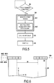
Figure 5 is a sequence diagram showing the main features of the printing method according to a particular example of the present disclosure. -
Figure 6 represents a particular example where the print bar is laterally moved according to an incremental implementation. -
Figure 1 schematically shows an example of aPWA printer 2 including aprint bar 4 which is used to print an image 8 on asubstrate 7. Theprint bar 4 includes an array ofnozzles 6 along its length. The twoend portions 4a of theprint bar 4 are not used along the entire print of image 8. The usedportion 4b ofprint bar 4 allows printing of the image 8 on thesubstrate 7. In this case, thenozzles 6 are driven to print characters 10 ("b", "c", "d", "e", and "f") on thesubstrate 7. - It has been observed that the nozzles in a PWA printer may not uniformly be used within the print bar. Statistically, certain nozzles within the print bar may be used more often than others, thereby causing non-uniform nozzle ageing along the print bar. This inherent non-uniformity of the nozzle ageing may be made even worse due to the international standardization of plot elements such as the border and the title block in mechanical and architecture drawings. If for instance a same vertical line extending along a margin is present in each of a plurality of printed pages, the nozzle(s) located in lateral alignment with these vertical lines will be more frequently used than others. The usage distribution of the nozzles may also be uneven along the print bar when a user sends multiple copies of the same job for instance.
- The highly used nozzles may negatively impact image quality. Non-uniform nozzle ageing may translate into defective behaviours (such as lower drop weight or lower velocity) sooner than the rest of the nozzles. Eventually, when the print bar is instructed to print a uniform area with nozzles that have dramatically different ages, the printing quality of the image on the substrate may become unacceptable due to, for example, visible coloration defects etc. At that point, the print bar may need to be replaced to maintain an acceptable level of printing quality.
- In
figure 1 , the PWAprinter 2 is performing one-pass printing. In the case wherenozzles - The present disclosure provides a PWA printer and a method for maximizing print bar performance uniformity by means of enabling the lateral movement of the print bar between print jobs or within the process of a printing job. By performing such lateral movements, a more uniform usage of the nozzles within the print bar can be achieved, thereby significantly improving the printing quality.
- An
inkjet PWA printer 20 according to a particular example of the present disclosure is now described in reference tofigure 2 . - The
PWA printer 20 includes aprint bar 24 extending in thedirection 24a of the print bar axis. A plurality ofnozzles 26 are provided along theprint bar 24, these nozzles being operable to print upon asubstrate 28. As indicated above, a substrate may be any sort of sheet-like or web-based medium, including paper, cardboard, plastic and textile. - Ink is supplied to the
nozzles 26 from anink tank 34. The number of nozzles may for instance be in the region of a hundred, one thousand or more, depending on the case. The structure of the nozzles in this example is conventional and will therefore not be described in detail. - The
PWA printer 20 further includes asubstrate transport mechanism 40 which in use is operative to transport thesubstrate 28 along a substrate transport path (in a Y direction) below thenozzles 26 of theprint bar 24. - The
PWA printer 20 also includes a printbar transport mechanism 36 which in use is operative to laterally move theprint bar 24 along the printbar axis direction 24a (i.e. the longitudinal direction of the print bar 24). The printbar transport mechanism 36 enables to laterally move theprint bar 24 relative to thesubstrate 28 in the X direction. In this example, thesubstrate 28 does not move in the X direction, the relative position with theprint bar 26 in the X direction being only controllable by laterally moving theprint bar 26. However, in another example, the substrate may also be moved laterally in the X direction to control the lateral position of the substrate relative to theprint bar 26. - In this particular example,
printer controller 22, such as a microprocessor, for example, is operative to control: - the firing of the nozzles;
- the lateral movement of the print bar in the X direction by sending commands to the print
bar transport mechanism 36; - the movement of the
substrate 28 in the Y direction by sending commands to thesubstrate transport mechanism 40; - the supply of the ink of the
nozzles 26 from theink tank 34. - In this example, the
controller 22 has access to a memory 38 (for example a computer memory such as a solid-state RAM). Images or jobs for the printer to print are stored inmemory 38 until they have been printed onto a substrate by the printer. - In this example, the
controller 22 has also access to a non-volatile rewritable memory 39 (such as an EEPROM for instance) in which is stored a computer program PG. Thememory 39 constitutes a recording medium according to the present disclosure, readable by a controller, and on which is stored a computer program PG according to the present disclosure, this computer program including instructions for carrying out a printing method according to the present disclosure. - The
controller 22 is operable to: - cause the
nozzles 26 to print a first image in a first lateral alignment on a substrate while theprint bar 24 is in a first lateral position (in the X direction); - laterally move the
print bar 24 from the first to a second lateral position (in the X direction); and - cause the
nozzles 26 to print a second image at the first lateral alignment while the print bar is in the second lateral position while theprint bar 24 is in the second lateral position. -
Figure 3 schematically shows an exemplary data structure of theimage 30 which is to be printed uponsubstrate 28. In this example,image 30 has a predetermined format and includes characters ("A", "B" and "C"). Theimage 30 can be represented by a plurality of data columns CL and a plurality of data rows RW. - To print
image 30, thecontroller 22 transmits data columns to theprint bar 24, each data column CL being input to acorresponding nozzle 26 so that thenozzles 26 which receive the data columns can collectively print thefull image 30 upon thesubstrate 28, one row after the other. - A method for printing an image in accordance with the present disclosure will now be described in reference with
figures 4 to 6 . - More specifically, the
PWA printer 20 carries out a printing method by executing the computer program PG stored inmemory 39. - The
nozzles 26 arranged within theprint bar 24 are here named N1 to N100 from left to right. As already indicated above, the number of nozzles may however be adapted depending on each case. - A particular example will now be considered where three
images PWA printer 20 upon three respectiveseparate substrates -
Figure 4A shows a first configuration where the nozzle N1 is positioned at a predetermined lateral position P1 in the X direction. This predetermined lateral position may be adapted to each case. In the present example, the predetermined lateral position is defined as the position in the X direction where the first data column CL1 of the image is to be printed on the substrate. Other predetermined lateral positions may be contemplated when implementing the present printer. - In the present case, nozzle N1 is positioned at position P1 in the X direction and, as such, is designated as the "first nozzle". A pointer PT is used in this example by the
controller 22 to identify the nozzle designated as first nozzle. - The
controller 22 is configured to input the first data column CL1 of each image to the "first nozzle" which is currently positioned at P1 at the time of processing, and to input the remaining data columns of each image to the nozzles adjacent to the first nozzle so that the nozzles can collectively print each image on a respective substrate. - It should be noted that several images may be printed on a same substrate or, alternatively, on dedicated substrates depending on the case. Each printing of an image constitutes a print job.
- More specifically, as a first print job, the
controller 22 inputs the first data column CL1 of thefirst image 30a to the nozzle N1 which is positioned at P1, and inputs the remaining data columns CL2 to CL98 ofimage 30a to the nozzles N2-N98 adjacent to CL1. The nozzles CL1 to CL98 are thus collectively configured to print each row RW in turn of thefirst image 30a on thesubstrate 28a. - In the case of
figure 4A , the nozzles CL99 and CL100 are not used to print theimage 30a on thesubstrate 28a. In this example, no data is input to nozzles CL99 and CL100 while N1 is the first nozzle. - As shown in
figure 5 , once the print job of thefirst image 30a is terminated, thecontroller 22 reconfigures (S4) the nozzles of theprint bar 24 and laterally moves (S6) theprint bar 24 along theprint bar axis 24a so that any subsequent image is the reconfiguration S4 allows to perform any subsequent print job without the lateral alignment of the image to be printed being modified. Without such nozzle reconfiguration, the lateral movement (S6) of theprint bar 24 would cause a lateral shift (in the X direction) of the subsequent images on their respective substrate. - S4 and S6 can be performed in any order, or simultaneously.
- An example of implementation of S4 and S6 is now described with reference to
figure 5 . - In this particular example, and according to the invention, the nozzle reconfiguration S4 includes selecting (S41) a nozzle as the "first nozzle" and inputting (S42) the data columns of the
image 30b to be printed to theappropriate nozzles 26 of theprint bar 24 based on the nozzle selection made in S41. - More specifically, in S41, the
controller 22 selects one nozzle among a predefined subset SB of nozzles within theprint bar 24. In the present case, the subset SB among which the nozzle selection is to be performed is composed of N1, N2 and N3. The size and content of the subset SB may be adapted to each case. - In this example, the nozzle selection S41 is performed at a time which is determined randomly by the
controller 22. In a preferred configuration, the nozzle selection S41 is always performed between two print jobs (i.e. while no printing is in progress in the PWA printer 20). - In another example, a nozzle selection S41 may be triggered by the
controller 22 each time it detects that at least one predetermined condition is met. In one example, before S4 and S6, thecontroller 22 may for instance verify (S2) on a regular basis (e.g. at the end of each print job) whether at least one predetermined condition is met. The at least one condition may include any one of the following: - a predetermined total number of print jobs already performed;
- a predetermined level of usage of the nozzles;
- a predetermined time elapsed since a previous nozzle selection; and
- usage of a predetermined plot type.
- In this particular example, each time the
controller 22 detects (S2) that the at least one predetermined condition is met, it proceeds with carrying out S4 and S6. The predetermined condition(s) can be defined beforehand by the user for instance and may be stored inmemory 39. - In a particular example, a nozzle selection S41 is triggered each time a (configurable) predetermined number of printed pages is reached.
- Furthermore, in S41, the
controller 22 is arranged such that it is statistically not always the same nozzle of the subset SB which is selected at S41. As a result, the selected nozzle will vary from time to time even though, in some configurations, a same nozzle within the subset SB may be selected several times in a row. - In a first arrangement, the
controller 22 may be configured to select (S41) at random the nozzle within the subset SB. - In a second arrangement, the
controller 22 may be configured to select (S41) the nozzle within the subset SB according to a predetermined rule. Thecontroller 22 may for instance be configured such that, at each nozzle selection (S41), the nozzle selected is different from the nozzle selected at the previous nozzle selection. - In a particular example, each of the nozzles of the subset SB are successively selected one after the other at each nozzle selection in a cyclic manner.
- In another example, the print bar is moved the same distance each time S6 is performed so as to select each nozzle of the subset SB successively until one end of the subset SB is reached at S41, and then the
print bar 24 is moved back step by step at each execution of S6 to the initial position offigure 4A (and so on). This "incremental" configuration allows to minimize the number of print bar movements. This latter example will be considered in the following part of the document. - As shown in
figure 4B , it is here assumed that thecontroller 22 selects (S41) the nozzle N2 within the subset SB as the new "first nozzle" which is to be positioned at P1 in the X direction. - The
controller 22 then transmits (S42) the image data to be printed to theprint bar 24 such that the first data column CL1 of thesecond image 30b is input to the selected nozzle N2, and the remaining data columns CL2-CL98 of said image are input respectively to the adjacent nozzles N3 to N99 so that the nozzles N2-N99 can print collectively thesecond image 30b. - The
controller 22 also positions (S6; MV1) laterally theprint bar 24 relative to the substrate on which thesecond image 30b is to be printed such that the selected nozzle N2 is laterally positioned in alignment with the predetermined position P1 on the substrate. - The second print job is then performed by the
PWA printer 20 without modifying the lateral alignment ofimage 30b on thesubstrate 28b in comparison withimage 30a onsubstrate 30a. The nozzles N2 to N99 print respectively the data columns CL1 to CL98 so as to print collectively thesecond image 30b on thesubstrate 28b. Nozzle N1 is now in position P2 and is no longer used in the process of printing. - The process of reconfiguring (S4) the
nozzles 26 of theprint bar 22 and moving laterally (S6) theprint bar 22 can be performed between each print job (in the time elapsed between print jobs) or, alternatively, only between certain print jobs, depending on the trigger being implemented (see above). -
Figure 4C shows a following stage of this example where thecontroller 22 again reconfigure thenozzles 26 within theprint bar 22 and moves laterally theprint bar 22 in the X direction. In this case, thecontroller 22 selects (S41) the nozzle N3 as the new "first nozzle" which is to be placed at the lateral position P1. Thecontroller 22 also transmits (S42) the image data to be printed to theprint bar 24 such that the first data column CL1 of thethird image 30c is input to the selected nozzle N3, and the remaining data columns CL2-CL98 of said image are input respectively to the adjacent nozzles N4 to N100 so that the nozzles N3-N100 can print collectively thethird image 30c. - The
controller 22 also positions (S6; MV2) laterally theprint bar 24 relative to thesubstrate 28c on which thethird image 30c is to be printed such that the selected nozzle N3 is positioned in alignment with the predetermined position P1 on the substrate. - The third print job is then performed by the
PWA printer 20 without modifying the lateral alignment ofimage 30c on thesubstrate 28c in comparison withimage 30a (or 30b) onsubstrate 30a (or 30b). The nozzles N3 to N100 print respectively the data columns CL1 to CL98 so as to print collectively thethird image 30c on thesubstrate 28c. -
Figure 6 shows an exemplary implementation of the incremental configuration described above. As indicated above, laterally moving the print bar according to MV1 and MV2 allows to print an image using respectively nozzle N2 and N3 as the "first nozzle" in position P1. At the two subsequent occurrence of S6, thecontroller 22 then laterally moves theprint bar 24 according to MV3 and MV4 (in the opposite direction to MV1 and MV2). As already mentioned, the "incremental" configuration allows to minimize the number of print bar movements. - The PWA printer according to the present disclosure is advantageous in that it enables to maximize print bar performance uniformity. In other words, with the present arrangement, a more uniform nozzle ageing can be achieved in a PWA printer, thereby significantly reducing the print defects that are usually observed with conventional PWA printers.
- The PWA printer also allows increasing the life of the nozzles in the print bar.
- In particular, when the present printing method is performed in a one-pass PWA printer, high printing quality can be maintained longer.
- The PWA printer and printing method according to the present disclosure can address the following problems:
- non-uniform ageing of the nozzles by forcing a more even use of nozzles;
- print bar defects by optimizing print bar positioning to the plot to be printed;
- colour changes induced by the print bar ends by reducing idle time of the nozzles at the two ends of the print bar.
- By indexing the nozzles and reconfiguring them at each lateral movement of the print bar, it is possible to print all the images according to a same lateral alignment. Any lateral movement of the figures being printed is prevented by the reconfiguration of the nozzles.
- It should be noted that the subset SB of nozzles should be defined such that each nozzle of the subset can be positioned in the predetermined position (i.e. P1 in the above examples) in the X direction. Accordingly, definition of the subset SB is limited by the moving capability range of the print bar along its axis. Each lateral movement of the print bar should not be so great that the print bar can no longer print the full width of the image to be printed.
- At S6, the print bar can be moved laterally in the X direction or at least in a direction having a component parallel to the print bar axis of the print bar.
- In the examples described above, it is the print bar which is moved laterally to control the lateral position of the nozzles relative to the substrate. In an alternative example, the PWA printer is arranged such that it laterally moves the substrate to control the lateral positioning at S6. In a particular example, the substrate and the print bar may be movable in the lateral direction.
- In the examples described above, the PWA printer performs each print job in one pass (in single-pass printing mode).
- In the examples described above, the controller laterally moves (S6) the print bar and reconfigures (S4) the nozzles accordingly once a print job is terminated. Alternatively, the controller may proceed with the lateral movement (S6) and the nozzle reconfiguration (S4) (in any order or simultaneously) while a print job of a given image is in progress. In that particular case, the controller interrupts the printing of an image in progress and proceeds with laterally moving the print bar and reconfiguring the nozzles as already explained so that the remaining portion of the image is printed in lateral alignment with the already printed portion of the image.
- As already indicated above, each print job may be performed on a separate substrate or, alternatively, several print jobs may be printed on distinct portions of a same substrate.
- According to a particular aspect of the present disclosure, the various stages of the printing method as described in the present disclosure are carried out by the PWA printer by running a computer program. The PWA printer may have for instance a hardware architecture of a computer, including for instance a processor capable of executing each operation in cooperation with appropriate memories.
- Accordingly, the present disclosure also provides a computer program on a recording medium, this computer program being arranged to be implemented by the PWA printer, and more generally by a controller, this computer program including instructions adapted for the implementation of a printing method as described in the present disclosure.
- The computer programs of the present disclosure can be expressed in any programming language, and can be in the form of source code, object code, or any intermediary code between source code and object code, such that in a partially-compiled form, for instance, or in any other appropriate form.
- The present disclosure also discloses a recording medium readable by the PWA printer, or more generally by a controller, this recording medium including computer program instructions as mentioned above.
- The recording medium previously mentioned can be any entity or device capable of storing the computer program. For example, the recording medium can include a storing means, such as a ROM memory (a CD-ROM or a ROM implemented in a microelectronic circuit), or a magnetic storing means such as a floppy disk or a hard disk for instance.
- The recording medium of the invention can correspond to a transmittable medium, such as an electrical or an optical signal, which can be conveyed via an electric or an optic cable, or by radio or any other appropriate means. The computer program according to the invention can in particular be downloaded from the Internet or a network of the like.
- Alternatively, the recording medium can correspond to an integrated circuit in which a computer program is loaded, the circuit being adapted to execute or to be used in the execution of the printing method of the present disclosure.
Claims (11)
- A page-wide array printer (20) for printing an image on a substrate, the printer including:- a print bar (24) along which a plurality of nozzles (26) are provided, said print bar being laterally movable along its print bar axis;- a controller operable to:wherein, once the print job of the first image is terminated, the controller reconfigures the nozzles and laterally moves the print bar along the print bar axis such that a subsequently printed image is printed in lateral alignment with the previously previous printed image, and▪ cause the nozzles to print a first image in a first lateral alignment on a substrate while the print bar is in a first lateral position, the printing of the first image being performed in one pass;▪ laterally move the print bar from the first to a second lateral position; and▪ cause the nozzles to print a second image at the first lateral alignment while the print bar is in the second lateral position, the printing of the second image being performed in one pass,
characterized in that the controller selects a nozzle as a first nozzle and inputs the data columns of the subsequent image to be printed to the appropriate nozzles of the print bar based on the nozzle selection. - The page-wide array printer of claim 1, wherein the controller moves the print bar between print jobs or within the process of a printing job.
- The page-wide array printer according to any previous claim, wherein the first and second images are distinct images or are distinct portions of a same image.
- A printing method carried out by a page wide array printer for printing an image on a substrate, the printer including a print bar along which a plurality of nozzles are provided, said print bar being movable along its print bar axis, said method including:- causing the nozzles to print, a first image in a first lateral alignment on a substrate while the print bar is in a first lateral position, the printing of the first image being performed in one pass;- laterally moving the print bar from the first to a second position;- causing the nozzles to print, in a single pass, a second image at the first lateral alignment while the print bar is in the second lateral position, the printing of the second image being performed in one pass;- once the print job of the first image is terminated, reconfiguring the nozzles and laterally moving the print bar along the print bar axis such that a subsequently printed image is printed in lateral alignment with the previously previous printed image; and characterized by- selecting a nozzle as a first nozzle and inputting the data columns of the subsequent image to be printed to the appropriate nozzles of the print bar based on the nozzle selection.
- The page-wide array printer of claim 1, wherein the controller is arranged such that it is statistically not always the same nozzle which is selected as the first nozzle.
- The page-wide array printer of claim 1, wherein at each nozzle selection, the nozzle selected is different from the nozzle selected at the previous nozzle selection.
- The page-wide array printer of claim 1, wherein the controller is arranged to perform said nozzle selection each time at least one predetermined condition is met.
- The page-wide array printer of claim 7, wherein the predetermined condition comprises any one of: a predetermined total number of print jobs already performed; a predetermined level of usage of the nozzles; a predetermined time elapsed since a previous nozzle selection; and usage of a predetermined plot type.
- The method of claim 4, further comprising performing the nozzle selection each time at least one predetermined condition is met.
- The method of claim 9, wherein the predetermined condition comprises any one of: a predetermined total number of print jobs already performed; a predetermined level of usage of the nozzles; a predetermined time elapsed since a previous nozzle selection; and usage of a predetermined plot type.
- Recording medium readable by a computer, said recording medium storing a computer program including instructions which, when executed by the computer, cause the computer to carry out a method according to any of claims 4, 9, and 10.
Applications Claiming Priority (1)
| Application Number | Priority Date | Filing Date | Title |
|---|---|---|---|
| PCT/EP2013/056965 WO2014161569A1 (en) | 2013-04-02 | 2013-04-02 | Page wide array printer |
Publications (2)
| Publication Number | Publication Date |
|---|---|
| EP2981415A1 EP2981415A1 (en) | 2016-02-10 |
| EP2981415B1 true EP2981415B1 (en) | 2019-10-09 |
Family
ID=48227173
Family Applications (1)
| Application Number | Title | Priority Date | Filing Date |
|---|---|---|---|
| EP13719423.9A Active EP2981415B1 (en) | 2013-04-02 | 2013-04-02 | Page wide array printer |
Country Status (4)
| Country | Link |
|---|---|
| US (2) | US9776392B2 (en) |
| EP (1) | EP2981415B1 (en) |
| CN (1) | CN105209262B (en) |
| WO (1) | WO2014161569A1 (en) |
Families Citing this family (5)
| Publication number | Priority date | Publication date | Assignee | Title |
|---|---|---|---|---|
| EP3225395B1 (en) * | 2014-11-29 | 2021-11-10 | Shibaura Mechatronics Corporation | Tablet printing device and tablet printing method |
| JP6607343B2 (en) * | 2015-03-30 | 2019-11-20 | パナソニックIpマネジメント株式会社 | Printing apparatus and method for manufacturing thin-film printed body |
| US10293625B2 (en) | 2015-04-24 | 2019-05-21 | Hewlett-Packard Development Company, L.P. | Print bar for a multi-pass printer and multi-pass page-wide-array printer |
| CN110027321A (en) * | 2019-04-22 | 2019-07-19 | 北京中科纳晨科技有限公司 | Printing device |
| JP7721287B2 (en) * | 2021-03-08 | 2025-08-12 | キヤノン株式会社 | Recording device and recording method |
Family Cites Families (15)
| Publication number | Priority date | Publication date | Assignee | Title |
|---|---|---|---|---|
| CA2278542A1 (en) | 1997-02-20 | 1998-08-27 | Xaar Technology Limited | Printer and method of printing |
| US6217150B1 (en) * | 1999-06-11 | 2001-04-17 | Lexmark International, Inc. | Method of printing with an ink jet printer using multiple carriage speeds |
| WO2002002331A1 (en) | 2000-06-30 | 2002-01-10 | Silverbrook Research Pty Ltd | Ink jet fault tolerance using adjacent nozzles |
| AU2000253742B2 (en) | 2000-06-30 | 2004-05-06 | Memjet Technology Limited | Ink jet fault tolerance using adjacent nozzles |
| US6942308B2 (en) | 2003-10-10 | 2005-09-13 | Hewlett-Packard Development Company, L.P. | Compensation of lateral position changes in printing |
| US7556334B2 (en) | 2004-11-04 | 2009-07-07 | Applied Materials, Inc. | Methods and apparatus for aligning print heads |
| KR100683176B1 (en) * | 2005-05-31 | 2007-02-15 | 삼성전자주식회사 | Image forming apparatus and image forming method |
| US20070024668A1 (en) | 2005-07-28 | 2007-02-01 | Xerox Corporation | Ink jet printer having print bar with spaced print heads |
| US7338144B2 (en) | 2005-09-29 | 2008-03-04 | Xerox Corporation | Ink jet printer having print head with partial nozzle redundancy |
| CN101663171B (en) * | 2006-11-28 | 2011-12-14 | Xjet有限公司 | Inkjet printing system with movable print heads and methods thereof |
| US8172359B2 (en) | 2007-10-03 | 2012-05-08 | Hewlett-Packard Development Company, L.P. | System and method for print head maintenance during continuous printing |
| US8057010B2 (en) * | 2007-11-16 | 2011-11-15 | Hewlett-Packard Development Company, L.P. | Method and printer for multi-pass page-wide array printing |
| FR2958207B1 (en) | 2010-03-30 | 2012-04-20 | Essilor Int | INKJET PRINTING TYPE DEPOSIT METHOD |
| DE102010037829A1 (en) | 2010-09-28 | 2012-03-29 | OCé PRINTING SYSTEMS GMBH | Printing element for ink printing apparatus e.g. color printer, has printing unit which is laid over print material at operating position and laid besides a transport unit at parking position |
| US8382244B2 (en) | 2011-06-08 | 2013-02-26 | Xerox Corporation | Method and system for actuating redundant electrical motors to move printheads laterally and improve reliability in a continuous web inkjet printer |
-
2013
- 2013-04-02 WO PCT/EP2013/056965 patent/WO2014161569A1/en not_active Ceased
- 2013-04-02 CN CN201380076642.3A patent/CN105209262B/en not_active Expired - Fee Related
- 2013-04-02 EP EP13719423.9A patent/EP2981415B1/en active Active
- 2013-04-02 US US14/780,806 patent/US9776392B2/en active Active
-
2017
- 2017-08-10 US US15/673,966 patent/US10391762B2/en active Active
Non-Patent Citations (1)
| Title |
|---|
| None * |
Also Published As
| Publication number | Publication date |
|---|---|
| WO2014161569A1 (en) | 2014-10-09 |
| US20170334194A1 (en) | 2017-11-23 |
| CN105209262B (en) | 2017-03-22 |
| US9776392B2 (en) | 2017-10-03 |
| EP2981415A1 (en) | 2016-02-10 |
| CN105209262A (en) | 2015-12-30 |
| US10391762B2 (en) | 2019-08-27 |
| US20160046120A1 (en) | 2016-02-18 |
Similar Documents
| Publication | Publication Date | Title |
|---|---|---|
| US10391762B2 (en) | Page wide array printer | |
| CN107150503B (en) | Method for printing pixels in an image and ink jet printer | |
| US10293620B2 (en) | Inkjet printing apparatus and inkjet printing method | |
| JP6206150B2 (en) | Droplet drying apparatus, droplet drying program, and image forming apparatus | |
| JP6040235B2 (en) | Duplicating device that prints on image-receiving material with a single pass printing method | |
| US9511589B2 (en) | Ink jet printer | |
| US8272707B2 (en) | Printing device, control method for a printing device, a program, and a recording medium | |
| JP2016112814A (en) | Image formation device and program | |
| US20170341380A1 (en) | Method of printing in a multipass mode and a printing apparatus for implementing such a method | |
| US10406804B2 (en) | Printing apparatus, printing method, and non-transitory computer-readable recording medium | |
| US10110756B2 (en) | Image processing apparatus and image processing method | |
| US20140152727A1 (en) | Processing printhead control data and printing system | |
| US11014351B2 (en) | Method for improving the droplet positioning of an inkjet printing device | |
| JP2016112781A (en) | Drier, image formation device and drying program | |
| CN113492589B (en) | Method for configuring an inkjet printer by means of a computer | |
| EP3118010B1 (en) | Printer apparatus | |
| US20090128599A1 (en) | Method and printer for multi-pass page-wide array printing | |
| US11820156B2 (en) | Method and device for increasing the print quality of an inkjet printing device | |
| JP2020121487A (en) | Recording apparatus and recording method | |
| JP5675392B2 (en) | Image recording device | |
| US20260113412A1 (en) | Inkjet printing apparatus, inkjet printing method, and storage medium | |
| EP3455074B1 (en) | Depositing print agent | |
| WO2020036102A1 (en) | Printing device and printing method | |
| JP2022076077A (en) | Printer and printing method | |
| JP5810013B2 (en) | Inkjet recording device |
Legal Events
| Date | Code | Title | Description |
|---|---|---|---|
| PUAI | Public reference made under article 153(3) epc to a published international application that has entered the european phase |
Free format text: ORIGINAL CODE: 0009012 |
|
| 17P | Request for examination filed |
Effective date: 20151002 |
|
| AK | Designated contracting states |
Kind code of ref document: A1 Designated state(s): AL AT BE BG CH CY CZ DE DK EE ES FI FR GB GR HR HU IE IS IT LI LT LU LV MC MK MT NL NO PL PT RO RS SE SI SK SM TR |
|
| AX | Request for extension of the european patent |
Extension state: BA ME |
|
| DAX | Request for extension of the european patent (deleted) | ||
| STAA | Information on the status of an ep patent application or granted ep patent |
Free format text: STATUS: EXAMINATION IS IN PROGRESS |
|
| 17Q | First examination report despatched |
Effective date: 20180418 |
|
| GRAP | Despatch of communication of intention to grant a patent |
Free format text: ORIGINAL CODE: EPIDOSNIGR1 |
|
| STAA | Information on the status of an ep patent application or granted ep patent |
Free format text: STATUS: GRANT OF PATENT IS INTENDED |
|
| RAP1 | Party data changed (applicant data changed or rights of an application transferred) |
Owner name: HEWLETT-PACKARD DEVELOPMENT COMPANY, L.P. |
|
| INTG | Intention to grant announced |
Effective date: 20190426 |
|
| GRAS | Grant fee paid |
Free format text: ORIGINAL CODE: EPIDOSNIGR3 |
|
| GRAA | (expected) grant |
Free format text: ORIGINAL CODE: 0009210 |
|
| STAA | Information on the status of an ep patent application or granted ep patent |
Free format text: STATUS: THE PATENT HAS BEEN GRANTED |
|
| AK | Designated contracting states |
Kind code of ref document: B1 Designated state(s): AL AT BE BG CH CY CZ DE DK EE ES FI FR GB GR HR HU IE IS IT LI LT LU LV MC MK MT NL NO PL PT RO RS SE SI SK SM TR |
|
| REG | Reference to a national code |
Ref country code: GB Ref legal event code: FG4D |
|
| REG | Reference to a national code |
Ref country code: CH Ref legal event code: EP |
|
| REG | Reference to a national code |
Ref country code: IE Ref legal event code: FG4D |
|
| REG | Reference to a national code |
Ref country code: DE Ref legal event code: R096 Ref document number: 602013061434 Country of ref document: DE |
|
| REG | Reference to a national code |
Ref country code: AT Ref legal event code: REF Ref document number: 1188336 Country of ref document: AT Kind code of ref document: T Effective date: 20191115 |
|
| REG | Reference to a national code |
Ref country code: NL Ref legal event code: MP Effective date: 20191009 |
|
| REG | Reference to a national code |
Ref country code: LT Ref legal event code: MG4D |
|
| REG | Reference to a national code |
Ref country code: AT Ref legal event code: MK05 Ref document number: 1188336 Country of ref document: AT Kind code of ref document: T Effective date: 20191009 |
|
| PG25 | Lapsed in a contracting state [announced via postgrant information from national office to epo] |
Ref country code: GR Free format text: LAPSE BECAUSE OF FAILURE TO SUBMIT A TRANSLATION OF THE DESCRIPTION OR TO PAY THE FEE WITHIN THE PRESCRIBED TIME-LIMIT Effective date: 20200110 Ref country code: PT Free format text: LAPSE BECAUSE OF FAILURE TO SUBMIT A TRANSLATION OF THE DESCRIPTION OR TO PAY THE FEE WITHIN THE PRESCRIBED TIME-LIMIT Effective date: 20200210 Ref country code: FI Free format text: LAPSE BECAUSE OF FAILURE TO SUBMIT A TRANSLATION OF THE DESCRIPTION OR TO PAY THE FEE WITHIN THE PRESCRIBED TIME-LIMIT Effective date: 20191009 Ref country code: AT Free format text: LAPSE BECAUSE OF FAILURE TO SUBMIT A TRANSLATION OF THE DESCRIPTION OR TO PAY THE FEE WITHIN THE PRESCRIBED TIME-LIMIT Effective date: 20191009 Ref country code: PL Free format text: LAPSE BECAUSE OF FAILURE TO SUBMIT A TRANSLATION OF THE DESCRIPTION OR TO PAY THE FEE WITHIN THE PRESCRIBED TIME-LIMIT Effective date: 20191009 Ref country code: SE Free format text: LAPSE BECAUSE OF FAILURE TO SUBMIT A TRANSLATION OF THE DESCRIPTION OR TO PAY THE FEE WITHIN THE PRESCRIBED TIME-LIMIT Effective date: 20191009 Ref country code: LT Free format text: LAPSE BECAUSE OF FAILURE TO SUBMIT A TRANSLATION OF THE DESCRIPTION OR TO PAY THE FEE WITHIN THE PRESCRIBED TIME-LIMIT Effective date: 20191009 Ref country code: NL Free format text: LAPSE BECAUSE OF FAILURE TO SUBMIT A TRANSLATION OF THE DESCRIPTION OR TO PAY THE FEE WITHIN THE PRESCRIBED TIME-LIMIT Effective date: 20191009 Ref country code: BG Free format text: LAPSE BECAUSE OF FAILURE TO SUBMIT A TRANSLATION OF THE DESCRIPTION OR TO PAY THE FEE WITHIN THE PRESCRIBED TIME-LIMIT Effective date: 20200109 Ref country code: ES Free format text: LAPSE BECAUSE OF FAILURE TO SUBMIT A TRANSLATION OF THE DESCRIPTION OR TO PAY THE FEE WITHIN THE PRESCRIBED TIME-LIMIT Effective date: 20191009 Ref country code: LV Free format text: LAPSE BECAUSE OF FAILURE TO SUBMIT A TRANSLATION OF THE DESCRIPTION OR TO PAY THE FEE WITHIN THE PRESCRIBED TIME-LIMIT Effective date: 20191009 Ref country code: NO Free format text: LAPSE BECAUSE OF FAILURE TO SUBMIT A TRANSLATION OF THE DESCRIPTION OR TO PAY THE FEE WITHIN THE PRESCRIBED TIME-LIMIT Effective date: 20200109 |
|
| PG25 | Lapsed in a contracting state [announced via postgrant information from national office to epo] |
Ref country code: HR Free format text: LAPSE BECAUSE OF FAILURE TO SUBMIT A TRANSLATION OF THE DESCRIPTION OR TO PAY THE FEE WITHIN THE PRESCRIBED TIME-LIMIT Effective date: 20191009 Ref country code: RS Free format text: LAPSE BECAUSE OF FAILURE TO SUBMIT A TRANSLATION OF THE DESCRIPTION OR TO PAY THE FEE WITHIN THE PRESCRIBED TIME-LIMIT Effective date: 20191009 Ref country code: IS Free format text: LAPSE BECAUSE OF FAILURE TO SUBMIT A TRANSLATION OF THE DESCRIPTION OR TO PAY THE FEE WITHIN THE PRESCRIBED TIME-LIMIT Effective date: 20200224 |
|
| PG25 | Lapsed in a contracting state [announced via postgrant information from national office to epo] |
Ref country code: AL Free format text: LAPSE BECAUSE OF FAILURE TO SUBMIT A TRANSLATION OF THE DESCRIPTION OR TO PAY THE FEE WITHIN THE PRESCRIBED TIME-LIMIT Effective date: 20191009 |
|
| REG | Reference to a national code |
Ref country code: DE Ref legal event code: R097 Ref document number: 602013061434 Country of ref document: DE |
|
| PG2D | Information on lapse in contracting state deleted |
Ref country code: IS |
|
| PG25 | Lapsed in a contracting state [announced via postgrant information from national office to epo] |
Ref country code: EE Free format text: LAPSE BECAUSE OF FAILURE TO SUBMIT A TRANSLATION OF THE DESCRIPTION OR TO PAY THE FEE WITHIN THE PRESCRIBED TIME-LIMIT Effective date: 20191009 Ref country code: CZ Free format text: LAPSE BECAUSE OF FAILURE TO SUBMIT A TRANSLATION OF THE DESCRIPTION OR TO PAY THE FEE WITHIN THE PRESCRIBED TIME-LIMIT Effective date: 20191009 Ref country code: RO Free format text: LAPSE BECAUSE OF FAILURE TO SUBMIT A TRANSLATION OF THE DESCRIPTION OR TO PAY THE FEE WITHIN THE PRESCRIBED TIME-LIMIT Effective date: 20191009 Ref country code: DK Free format text: LAPSE BECAUSE OF FAILURE TO SUBMIT A TRANSLATION OF THE DESCRIPTION OR TO PAY THE FEE WITHIN THE PRESCRIBED TIME-LIMIT Effective date: 20191009 Ref country code: IS Free format text: LAPSE BECAUSE OF FAILURE TO SUBMIT A TRANSLATION OF THE DESCRIPTION OR TO PAY THE FEE WITHIN THE PRESCRIBED TIME-LIMIT Effective date: 20200209 |
|
| PLBE | No opposition filed within time limit |
Free format text: ORIGINAL CODE: 0009261 |
|
| STAA | Information on the status of an ep patent application or granted ep patent |
Free format text: STATUS: NO OPPOSITION FILED WITHIN TIME LIMIT |
|
| PG25 | Lapsed in a contracting state [announced via postgrant information from national office to epo] |
Ref country code: SK Free format text: LAPSE BECAUSE OF FAILURE TO SUBMIT A TRANSLATION OF THE DESCRIPTION OR TO PAY THE FEE WITHIN THE PRESCRIBED TIME-LIMIT Effective date: 20191009 Ref country code: SM Free format text: LAPSE BECAUSE OF FAILURE TO SUBMIT A TRANSLATION OF THE DESCRIPTION OR TO PAY THE FEE WITHIN THE PRESCRIBED TIME-LIMIT Effective date: 20191009 Ref country code: IT Free format text: LAPSE BECAUSE OF FAILURE TO SUBMIT A TRANSLATION OF THE DESCRIPTION OR TO PAY THE FEE WITHIN THE PRESCRIBED TIME-LIMIT Effective date: 20191009 |
|
| 26N | No opposition filed |
Effective date: 20200710 |
|
| PG25 | Lapsed in a contracting state [announced via postgrant information from national office to epo] |
Ref country code: SI Free format text: LAPSE BECAUSE OF FAILURE TO SUBMIT A TRANSLATION OF THE DESCRIPTION OR TO PAY THE FEE WITHIN THE PRESCRIBED TIME-LIMIT Effective date: 20191009 Ref country code: MC Free format text: LAPSE BECAUSE OF FAILURE TO SUBMIT A TRANSLATION OF THE DESCRIPTION OR TO PAY THE FEE WITHIN THE PRESCRIBED TIME-LIMIT Effective date: 20191009 |
|
| REG | Reference to a national code |
Ref country code: CH Ref legal event code: PL |
|
| PG25 | Lapsed in a contracting state [announced via postgrant information from national office to epo] |
Ref country code: CH Free format text: LAPSE BECAUSE OF NON-PAYMENT OF DUE FEES Effective date: 20200430 Ref country code: LI Free format text: LAPSE BECAUSE OF NON-PAYMENT OF DUE FEES Effective date: 20200430 Ref country code: LU Free format text: LAPSE BECAUSE OF NON-PAYMENT OF DUE FEES Effective date: 20200402 |
|
| REG | Reference to a national code |
Ref country code: BE Ref legal event code: MM Effective date: 20200430 |
|
| PG25 | Lapsed in a contracting state [announced via postgrant information from national office to epo] |
Ref country code: BE Free format text: LAPSE BECAUSE OF NON-PAYMENT OF DUE FEES Effective date: 20200430 |
|
| PG25 | Lapsed in a contracting state [announced via postgrant information from national office to epo] |
Ref country code: IE Free format text: LAPSE BECAUSE OF NON-PAYMENT OF DUE FEES Effective date: 20200402 |
|
| PGFP | Annual fee paid to national office [announced via postgrant information from national office to epo] |
Ref country code: GB Payment date: 20220323 Year of fee payment: 10 |
|
| PG25 | Lapsed in a contracting state [announced via postgrant information from national office to epo] |
Ref country code: TR Free format text: LAPSE BECAUSE OF FAILURE TO SUBMIT A TRANSLATION OF THE DESCRIPTION OR TO PAY THE FEE WITHIN THE PRESCRIBED TIME-LIMIT Effective date: 20191009 Ref country code: MT Free format text: LAPSE BECAUSE OF FAILURE TO SUBMIT A TRANSLATION OF THE DESCRIPTION OR TO PAY THE FEE WITHIN THE PRESCRIBED TIME-LIMIT Effective date: 20191009 Ref country code: CY Free format text: LAPSE BECAUSE OF FAILURE TO SUBMIT A TRANSLATION OF THE DESCRIPTION OR TO PAY THE FEE WITHIN THE PRESCRIBED TIME-LIMIT Effective date: 20191009 |
|
| PGFP | Annual fee paid to national office [announced via postgrant information from national office to epo] |
Ref country code: FR Payment date: 20220323 Year of fee payment: 10 |
|
| PG25 | Lapsed in a contracting state [announced via postgrant information from national office to epo] |
Ref country code: MK Free format text: LAPSE BECAUSE OF FAILURE TO SUBMIT A TRANSLATION OF THE DESCRIPTION OR TO PAY THE FEE WITHIN THE PRESCRIBED TIME-LIMIT Effective date: 20191009 |
|
| PGFP | Annual fee paid to national office [announced via postgrant information from national office to epo] |
Ref country code: DE Payment date: 20220322 Year of fee payment: 10 |
|
| REG | Reference to a national code |
Ref country code: DE Ref legal event code: R119 Ref document number: 602013061434 Country of ref document: DE |
|
| GBPC | Gb: european patent ceased through non-payment of renewal fee |
Effective date: 20230402 |
|
| PG25 | Lapsed in a contracting state [announced via postgrant information from national office to epo] |
Ref country code: GB Free format text: LAPSE BECAUSE OF NON-PAYMENT OF DUE FEES Effective date: 20230402 |
|
| PG25 | Lapsed in a contracting state [announced via postgrant information from national office to epo] |
Ref country code: GB Free format text: LAPSE BECAUSE OF NON-PAYMENT OF DUE FEES Effective date: 20230402 Ref country code: FR Free format text: LAPSE BECAUSE OF NON-PAYMENT OF DUE FEES Effective date: 20230430 Ref country code: DE Free format text: LAPSE BECAUSE OF NON-PAYMENT OF DUE FEES Effective date: 20231103 |