EP2981026A1 - Method and system for information interaction among systems in the same end in drni - Google Patents
Method and system for information interaction among systems in the same end in drni Download PDFInfo
- Publication number
- EP2981026A1 EP2981026A1 EP14791616.7A EP14791616A EP2981026A1 EP 2981026 A1 EP2981026 A1 EP 2981026A1 EP 14791616 A EP14791616 A EP 14791616A EP 2981026 A1 EP2981026 A1 EP 2981026A1
- Authority
- EP
- European Patent Office
- Prior art keywords
- adjacent
- present system
- portal
- key value
- present
- Prior art date
- Legal status (The legal status is an assumption and is not a legal conclusion. Google has not performed a legal analysis and makes no representation as to the accuracy of the status listed.)
- Granted
Links
- 238000000034 method Methods 0.000 title claims abstract description 67
- 230000003993 interaction Effects 0.000 title claims abstract description 14
- 238000004220 aggregation Methods 0.000 claims abstract description 58
- 230000002776 aggregation Effects 0.000 claims abstract description 57
- 230000000737 periodic effect Effects 0.000 claims abstract description 7
- 238000001914 filtration Methods 0.000 claims description 4
- 238000004891 communication Methods 0.000 abstract description 4
- 230000006870 function Effects 0.000 description 33
- 230000008569 process Effects 0.000 description 17
- 238000010586 diagram Methods 0.000 description 9
- 238000012545 processing Methods 0.000 description 8
- 230000001960 triggered effect Effects 0.000 description 6
- 230000004931 aggregating effect Effects 0.000 description 3
- 230000000875 corresponding effect Effects 0.000 description 3
- 238000005516 engineering process Methods 0.000 description 3
- 230000004048 modification Effects 0.000 description 3
- 238000012986 modification Methods 0.000 description 3
- 238000012546 transfer Methods 0.000 description 3
- 238000011282 treatment Methods 0.000 description 3
- 238000005315 distribution function Methods 0.000 description 2
- 230000009977 dual effect Effects 0.000 description 2
- 230000007246 mechanism Effects 0.000 description 2
- 241000284212 Euproctis actor Species 0.000 description 1
- 210000004556 brain Anatomy 0.000 description 1
- 238000006243 chemical reaction Methods 0.000 description 1
- 238000001514 detection method Methods 0.000 description 1
- 238000011161 development Methods 0.000 description 1
- 230000006855 networking Effects 0.000 description 1
- 230000003287 optical effect Effects 0.000 description 1
Images


Classifications
-
- H—ELECTRICITY
- H04—ELECTRIC COMMUNICATION TECHNIQUE
- H04L—TRANSMISSION OF DIGITAL INFORMATION, e.g. TELEGRAPHIC COMMUNICATION
- H04L41/00—Arrangements for maintenance, administration or management of data switching networks, e.g. of packet switching networks
- H04L41/12—Discovery or management of network topologies
-
- H—ELECTRICITY
- H04—ELECTRIC COMMUNICATION TECHNIQUE
- H04L—TRANSMISSION OF DIGITAL INFORMATION, e.g. TELEGRAPHIC COMMUNICATION
- H04L45/00—Routing or path finding of packets in data switching networks
- H04L45/24—Multipath
- H04L45/245—Link aggregation, e.g. trunking
-
- H—ELECTRICITY
- H04—ELECTRIC COMMUNICATION TECHNIQUE
- H04L—TRANSMISSION OF DIGITAL INFORMATION, e.g. TELEGRAPHIC COMMUNICATION
- H04L45/00—Routing or path finding of packets in data switching networks
- H04L45/28—Routing or path finding of packets in data switching networks using route fault recovery
-
- H—ELECTRICITY
- H04—ELECTRIC COMMUNICATION TECHNIQUE
- H04L—TRANSMISSION OF DIGITAL INFORMATION, e.g. TELEGRAPHIC COMMUNICATION
- H04L47/00—Traffic control in data switching networks
- H04L47/10—Flow control; Congestion control
- H04L47/41—Flow control; Congestion control by acting on aggregated flows or links
-
- H—ELECTRICITY
- H04—ELECTRIC COMMUNICATION TECHNIQUE
- H04L—TRANSMISSION OF DIGITAL INFORMATION, e.g. TELEGRAPHIC COMMUNICATION
- H04L69/00—Network arrangements, protocols or services independent of the application payload and not provided for in the other groups of this subclass
- H04L69/14—Multichannel or multilink protocols
-
- Y—GENERAL TAGGING OF NEW TECHNOLOGICAL DEVELOPMENTS; GENERAL TAGGING OF CROSS-SECTIONAL TECHNOLOGIES SPANNING OVER SEVERAL SECTIONS OF THE IPC; TECHNICAL SUBJECTS COVERED BY FORMER USPC CROSS-REFERENCE ART COLLECTIONS [XRACs] AND DIGESTS
- Y02—TECHNOLOGIES OR APPLICATIONS FOR MITIGATION OR ADAPTATION AGAINST CLIMATE CHANGE
- Y02D—CLIMATE CHANGE MITIGATION TECHNOLOGIES IN INFORMATION AND COMMUNICATION TECHNOLOGIES [ICT], I.E. INFORMATION AND COMMUNICATION TECHNOLOGIES AIMING AT THE REDUCTION OF THEIR OWN ENERGY USE
- Y02D30/00—Reducing energy consumption in communication networks
- Y02D30/50—Reducing energy consumption in communication networks in wire-line communication networks, e.g. low power modes or reduced link rate
Definitions
- the present invention relates to the network communication protection technology, and more particularly, to a method and system for information interaction among systems in a same portal in a DRNI (Distributed Resilient Network Interconnected).
- DRNI Distributed Resilient Network Interconnected
- the IEEE Standards Association proposed extended link aggregation, which achieves the link and node dual redundant network interconnected protection demands by means of a distribution link aggregation group DRNI, namely, an portal of the aggregation group consists of a plurality of nodes, and the aggregation links of the plurality of nodes form a link aggregation group (referred to as LAG).
- two portals A and B in the link aggregation group consist of two and three systems, respectively: the portal A comprises system 1 and system 2, and the portal B comprises system 3, system 4, and system 5, a plurality of links of these five systems are aggregated together to form a distributed LAG.
- the portal A comprises system 1 and system 2
- the portal B comprises system 3, system 4, and system 5, a plurality of links of these five systems are aggregated together to form a distributed LAG.
- this distributed LAG dual protection of links and nodes can be achieved.
- the system 1 and the system 2 in the Portal A need to be connected through an intra-portal link, thus ensuring that the portal B sees that the portal A to which it is connected via a link aggregation group is a logical node; similarly, the system 3, the system 4 and the system 5 in the portal B also need to be connected through intra-portal links, thus ensuring that the portal A sees that the portal B to which it is connected via a link aggregation group is a logical node.
- LACP Link Aggregation Control Protocol
- the DRNI interconnects two or more systems through a distributed relay (referred to as DR), wherein each system operates the link aggregation, thereby forming one Portal.
- DR distributed relay
- the peer system considers what it is connected to is an analog system.
- various systems within a Portal need to interact and negotiate through a distributed relay to unify parameters between these systems and notify to the LACP to interact with the other portal of the link aggregation group.
- the DR functions to send messages (UP messages) received from the aggregation interface to the gateway or to discard them, and to send messages (DOWN messages) received from the gateway interface to the aggregator or to discard them.
- the DR decides whether to forward or discard a message according to the conversation to which the received message belongs, and configurations of the gateway algorithm and the port algorithm are also operated based on the conversation. Traffic of each conversation is assigned with one gateway link at most, and the traffic of each conversation also corresponds to one aggregation interface at most.
- the DR in multiple systems within one portal do not have the consistent message distribution way, it will cause problems such as messages out of order, forming a ring or message loss, and therefore when there is the case that the distribution ways are inconsistent between multiple systems, it is also needed to interact via the distributed relay to unify the distribution ways in different systems or isolate the service traffic the distribution ways of which are not uniform.
- the object of the present invention is to provide a method and system for information interaction between systems in a same portal within a DRNI in order to achieve link aggregation of a plurality of systems.
- the present invention provides a method for information interaction between systems in a same portal in a distributed resilient network interconnection, used in each system in a portal of a link aggregation group, comprising:
- the method further comprises:
- the method further comprises: after determining the operational Key value of the present system, negotiating a unified conversation distribution way with the adjacent system.
- said judging that the present system and the adjacent system can form the same portal comprises:
- said performing a matching check on the system information of the adjacent system carried in the received DRCP message and the system information of the present system comprises:
- said performing a matching check on the system information of the adjacent system carried in the received DRCP message and the system information of the present system further comprises:
- the method further comprises: if the matching check is passed, saving the system information of the adjacent system carried in the DRCP message.
- said sending a DRCP message comprises: periodically sending the DRCP message; the method further comprises:
- said sending a DRCP message comprises:
- said determining an operational Key value of the present system comprises:
- said determining an operational Key value of the present system comprises:
- said determining an operational Key value of the present system comprises:
- the method further comprises:
- said negotiating a unified conversation distribution way with the adjacent system comprises:
- said negotiating the conversation distribution way carried in the DRCP message sent by the adjacent system and the conversation distribution way of the present system comprises: comparing the conversation distribution way carried in the DRCP message sent by the adjacent system with the conversation distribution way of the present system, and for conversations that are consistent in the conversation distribution way, the distributed relay distributing traffic of the conversations according to the consistent conversation distribution way, for conversations that have conflicts in the conversation distribution way, the distributed relay filtering or discarding traffic of the conversations that have conflicts in the conversation distribution way.
- said setting up a distributed relay channel within the present system comprises:
- the method further comprises:
- the method further comprises:
- said modifying at least part of LACP parameters in the system information of the present system comprises: modifying the operational key value and/or the System ID of the present system, or restoring the operational Key value to the administration Key value.
- the distributed relay is restored to the configuration of the conversation distribution way before the negotiation.
- the DRCP message sent via the intra-portal interface also carries the system information and/or conversation distribution ways of other adjacent systems connected with the present system.
- the present invention also provides a system for implementing distributed relay control in a distributed resilient network interconnection, comprising:
- the receiving state machine being configured to perform the matching check on the system information of the present system and the adjacent system, comprises:
- the receiving state machine being configured to perform the matching check on the system information of the present system and the adjacent system, further comprises:
- the negotiating state machine being configured to determine the operational Key value of the present system, and ensure that the operational Key value is consistent with the operational Key value of the adjacent system, comprises:
- the negotiating state machine being configured to determine the operational Key value of the present system, and ensure that the operational Key value is consistent with the operational Key value of the adjacent system, comprises: according to an administration Key value of the present system and a received administration Key value of the adjacent system, the negotiating state machine calculating the operational Key value of the present system.
- the negotiating state machine is further configured to: after determining the operational Key value of the present system, send the operational Key value of the present system to a peer portal of the distributed resilient network interconnection through a Link Aggregation Control Protocol (LACP) message.
- LACP Link Aggregation Control Protocol
- the synchronizing state machine being configured to negotiate the unified conversation distribution way with the adjacent system, comprises: negotiating the conversation distribution way carried in the DRCP message sent by the adjacent system and the conversation distribution way of the present system, and configuring a traffic distribution way of the distributed relay in the present system in accordance with the negotiated conversation distribution way.
- the synchronizing state machine being configured to negotiate the conversation distribution way carried in the DRCP message sent by the adjacent system and the conversation distribution way of the present system, comprises:
- the conversation distribution way comprises any one or combination of the following two parameters: a gateway system selection and an aggregator/aggregation port selection.
- the synchronizing state machine is further configured to: before negotiating the unified conversation distribution way with the adjacent system, disable a data traffic forwarding function of an intra-portal link with the adjacent system; after negotiating the unified conversation distribution way with the adjacent system and unifying a distribution algorithm, enable the data traffic forwarding function of the intra-portal link.
- the receiving state machine is further configured to: if the DRCP message sent by the adjacent system again is not received on time or the received DRCP message sent by the adjacent system again does not pass the matching check, judge whether it is needed to modify the system information of the present system based on the policy; if it is needed to modify, modify at least part of LACP parameters in the system information of the present system, and send the modified LACP parameter(s) to the peer portal of the distributed resilient network interconnection through the LACP message; wherein the modified LACP parameter(s) of the present system is/are at least not identical with the LACP parameters of the adjacent system.
- the receiving state machine being configured to: modify the at least part of the LACP parameters in the system information of the present system, comprises: the receiving state machine modifying the operational Key value and/or the System ID of the present system, or restoring the operational Key value to the administration Key value.
- the synchronizing state machine is further configured to: when the intra-portal link with the adjacent system fails or the intra-portal link is unavailable, restore the distributed relay to the configuration of the conversation distribution way before the negotiation.
- the DRCP message sent by the sending state machine via the intra-portal interface also carries system information and/or conversation distribution way of other adjacent systems connected with the present system.
- the Distributed Relay Control Protocol within the system mainly comprises: a receiving state machine, a synchronizing state machine and a sending state machine, and may further comprise: a negotiating state machine and a periodic sending state machine.
- the receiving state machine is mainly used for receiving the DRCP message sent by an adjacent system.
- the received DRCP message comprises system information (Actor Info) of the adjacent system which sends the message, and may also comprise system information (Partner_Info) of other systems connected with the adjacent system stored by the adjacent system which sends the message.
- the main tasks of the receiving state machine are:
- the negotiating state machine is used to determine the Operational Key of the present system, ensuring that the Operational Key value unified with the adjacent system which sends the DRCP message is obtained, and the Operational Key is a parameter carried in the LACP message.
- the synchronizing state machine is mainly used to set up a DR channel, forward data at the DRNI interface and distribute the traffic between the systems, mainly comprising:
- DRCP.State Synchronization
- the sending state machine is used to send the DRCP message through the intra-portal interface, herein sending the DRCP message can be triggered through commands sent from other state machines or can also be triggered by a periodic sending state machine.
- sending the DRCP message can be triggered through commands sent from other state machines or can also be triggered by a periodic sending state machine.
- the periodic sending state machine is used to decide when the present system sends the DRCP message so as to transfer relevant information and maintain connectivity with other systems.
- the interior of the periodic sending state machine has a timer, and when the timer expires, a NTT (Need to transmit) will be produced, to trigger the sending state machine to send the DRCP message.
- NTT Need to transmit
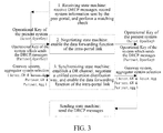
- the distributed relay control protocol needs to transfer some information in these state machines during the state switching process. As shown in FIG. 3 , it comprises:
- the protocol interaction process between the system 1 and the system 2 in the portal A in FIG. 1 is taken as an example for further illustration. Assume that the system 1 considers itself as an Actor and the system 2 as a Partner. Similarly, the system 2 considers itself as the Actor and the system 1 as the Partner. The system 1 receives the Actor information sent by the system 2, and saves the Actor Information as its own Partner information.
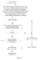
- FIG. 4 For the receiving state machine in the system 1, its specific process is shown in FIG. 4 , comprising:
- the timeout ID Expire is set as False, indicating no timeout yet
- the Check (Actor, Partner) mainly functions to perform the matching check on multiple parameters, as shown in FIG. 5 , comprising:
- the negotiating state machine will be triggered to process the Operational Key of the present system.
- the specific process is shown in FIG. 6 , comprising:
- the portal B may be aggregated with the aggregation links connected with the portal A into a distributed aggregation group, forming the DRNI.
- ModifyKey namely:
- DRCP.State Synchronization
- FIG. 7 The processing procedure of the synchronizing state machine in the system 1 is shown in FIG. 7 , comprising:
- the DR can already be used for forwarding data.
- the DRNI already can work normally.
- This function will set up the connection between the forwarding and aggregation group interfaces, thus ensuring that the DRNI interface can receive and send data messages.
- the NTT can be triggered to notify the system 2.
- the data traffic is distributed based on the conversation ID of the traffic.
- the traffic conversation distribution way of the system 1 is taken for example, according to information of the Actor_Agg and the Partner_Agg, as well as the Actor_GW and the Partner_GW, the distribution way of the DR in the system 1 is modified as shown in Table 1 below: Table 1 The distribution way of the DR in the system 1 Gateway (GW) Aggregator (Agg) Port to which the conversation sends System 1 Any The system 1 forwards to other portals System 2 System 1 Aggregation portal of the system 1 System 2 Discard
- the data traffic can be forwarded between the system 1 and the system 2 based on the configuration.
- the synchronizing state machine in the system 1 can also process according to the following procedure, as shown in FIG. 8 :
- NTT True to notify the system 2 that the DR of the present system has not been set up yet.
- the DR already can be used for forwarding data.
- the DRNI already can work normally.
- the data traffic is distributed based on the conversation ID of the traffic.
- the traffic conversation distribution way of the system 1 is taken for example, according to the information of the Actor_Agg and the Partner_Agg, as well as the Actor_GW and the Partner_GW, the DR distribution way in the system 1 is modified as shown in Table 1.
- the data traffic can perform the data traffic forwarding between the system 1 and the system 2 based on the configuration.
- the DR can distribute the traffic formally in accordance with the distribution configuration method after the negotiation.
- the distributed relay control protocol be in the forwarding state, and can the DR distribute the traffic in accordance with the distribution way negotiated by the system 1 and the system 2.
- the NeedtoCoordination () function is used for unifying the traffic distribution of the system 1 and the system 2.
- the DRNI has data traffic in two directions, one is data traffic sent from other network ports to the aggregation port and the other is data traffic received by the aggregation port and sent to other network ports.
- the traffic in the first direction needs to select whether to send from the aggregator of the system 1 or the aggregator of the system 2 to the aggregation interface in the DR, and at this time, the traffic distribution is determined by the Actor_Info.Agg; the traffic in the second direction needs to select whether to send from the system 1 to other network ports or to send to the system 2 via the Intra-portal link and then to other network ports in the DR, and at this time, the traffic distribution is determined by the Actor_Info.GW. Therefore, the NeedtoCoordination () function is used for unifying the Actor_Info.Agg and the Partner_Info.Agg, as well as the Actor_Info.GW and the Partner_Info.GW, to prevent conflicts.
- the specific process is as shown in FIG. 9 , comprising:
- the established policy includes but is not limited to the following two kinds:
- each module/unit in the abovementioned embodiments may be realized in a form of hardware, or in a form of software function modules.
- the present invention is not limited to any specific form of hardware and software combinations.
- the embodiments of the present invention achieve the control communication between multiple systems in one portal in the distributed link aggregation group, and can effectively achieve protection on the interconnected interface, not only protection on the link but also protection on the level of node, after multiple systems aggregate into one aggregation group.
Landscapes
- Engineering & Computer Science (AREA)
- Computer Networks & Wireless Communication (AREA)
- Signal Processing (AREA)
- Computer Security & Cryptography (AREA)
- Data Exchanges In Wide-Area Networks (AREA)
- Communication Control (AREA)
- Computer And Data Communications (AREA)
Abstract
Description
- The present invention relates to the network communication protection technology, and more particularly, to a method and system for information interaction among systems in a same portal in a DRNI (Distributed Resilient Network Interconnected).
- With the rapid development of broadband services, network-to-network interconnection is used more and more to carry more services. According to the technology used, there may be a variety of ways within the network to protect links and nodes thereon. With increasingly strong demands for traffic protection and increasingly high requirements, operators proposed the demands for protection on the network interconnection. Herein the protection can be achieved by using port aggregation, and the commonly used method can be port aggregation or ring protection. In the existing IEEE (Institute of Electrical and Electronics Engineers) standard 802.1AX, the link aggregation currently supports the port aggregation on one node and therefore can only be used for link protection but cannot protect nodes at the network edge interface.
- Therefore, in order to apply to the diversity of network-to-network interconnected area networking ways, and to achieve not only the protection for links but also the protection for edge nodes, the IEEE Standards Association proposed extended link aggregation, which achieves the link and node dual redundant network interconnected protection demands by means of a distribution link aggregation group DRNI, namely, an portal of the aggregation group consists of a plurality of nodes, and the aggregation links of the plurality of nodes form a link aggregation group (referred to as LAG). As shown in
FIG.1 , two portals A and B in the link aggregation group consist of two and three systems, respectively: the portal A comprisessystem 1 andsystem 2, and the portal B comprisessystem 3, system 4, and system 5, a plurality of links of these five systems are aggregated together to form a distributed LAG. Through this distributed LAG, dual protection of links and nodes can be achieved. - The
system 1 and thesystem 2 in the Portal A need to be connected through an intra-portal link, thus ensuring that the portal B sees that the portal A to which it is connected via a link aggregation group is a logical node; similarly, thesystem 3, the system 4 and the system 5 in the portal B also need to be connected through intra-portal links, thus ensuring that the portal A sees that the portal B to which it is connected via a link aggregation group is a logical node. After a plurality of links interconnected between the logical nodes in the portal A and the logic nodes in the portal B form a distributed link aggregation group through the LACP (Link Aggregation Control Protocol) control message interaction. - The DRNI interconnects two or more systems through a distributed relay (referred to as DR), wherein each system operates the link aggregation, thereby forming one Portal. For the peer system connected to the Portal, the peer system considers what it is connected to is an analog system. For this purpose, various systems within a Portal need to interact and negotiate through a distributed relay to unify parameters between these systems and notify to the LACP to interact with the other portal of the link aggregation group.
- There are three kinds of interfaces on the DR, and they are Gateway Interface, Intra-portal Interface and Aggregate Interface, respectively. The DR functions to send messages (UP messages) received from the aggregation interface to the gateway or to discard them, and to send messages (DOWN messages) received from the gateway interface to the aggregator or to discard them. The DR decides whether to forward or discard a message according to the conversation to which the received message belongs, and configurations of the gateway algorithm and the port algorithm are also operated based on the conversation. Traffic of each conversation is assigned with one gateway link at most, and the traffic of each conversation also corresponds to one aggregation interface at most. When the DR in multiple systems within one portal do not have the consistent message distribution way, it will cause problems such as messages out of order, forming a ring or message loss, and therefore when there is the case that the distribution ways are inconsistent between multiple systems, it is also needed to interact via the distributed relay to unify the distribution ways in different systems or isolate the service traffic the distribution ways of which are not uniform.
- The object of the present invention is to provide a method and system for information interaction between systems in a same portal within a DRNI in order to achieve link aggregation of a plurality of systems.
- To solve the foregoing problem, the present invention provides a method for information interaction between systems in a same portal in a distributed resilient network interconnection, used in each system in a portal of a link aggregation group, comprising:
- sending a distributed relay control protocol (DRCP) message via an intra-portal interface, wherein at least system information of a present system is carried;
- after receiving a DRCP message sent by an adjacent system, if it is judged that the present system and the adjacent system can form an portal of the distributed resilient network interconnection, determining an operational Key value of the present system.
- Preferably, the method further comprises:
- after determining the operational Key value of the present system, setting up a distributed relay channel within the present system.
- Preferably, the method further comprises: after determining the operational Key value of the present system, negotiating a unified conversation distribution way with the adjacent system.
- Preferably, said judging that the present system and the adjacent system can form the same portal comprises:
- performing a matching check on the system information of the adjacent system carried in the received DRCP message and the system information of the present system, if the matching check is passed, determining that the present system and the adjacent system can form the same portal.
- Preferably, said performing a matching check on the system information of the adjacent system carried in the received DRCP message and the system information of the present system comprises:
- judging whether a Portal ID of the present system and a Portal ID of the adjacent system are consistent; and/or judging whether an Emulated System ID of the present system and a Emulated System ID of the adjacent system are consistent;
- the matching check being passed comprises: the Portal ID of the present system and the Portal ID of the adjacent system being the same, and/or the Emulated System ID of the present system and the Emulated System ID of the adjacent system being the same.
- Preferably, said performing a matching check on the system information of the adjacent system carried in the received DRCP message and the system information of the present system further comprises:
- judging whether a System Number of the present system conflicts with a System Number of the adjacent system;
- the matching check being passed comprises: the Portal ID and/or Emulated System ID of the present system and the Portal ID and/or Emulated System ID of the adjacent system being the same respectively, and the System Number of the present system not conflicting with the System Number of the adjacent system.
- Preferably, the method further comprises: if the matching check is passed, saving the system information of the adjacent system carried in the DRCP message.
- Preferably, said sending a DRCP message comprises: periodically sending the DRCP message;
the method further comprises: - after receiving the DRCP message sent by the adjacent system each time, starting a timer;
- if the DRCP message sent by the adjacent system is not received when the timer expires, or if the DRCP message sent by the adjacent system is received before the timer expires but the matching check is not passed, determining that the present system and the adjacent system no longer can form a portal of the distributed resilient network interconnection.
- Preferably, said sending a DRCP message comprises:
- when there is a parameter updated in the system information of the present system, sending the DRCP message.
- Preferably, said determining an operational Key value of the present system comprises:
- if it is judged that the operational Key value of the present system and the operational Key value of the adjacent system are the same, remaining the operational Key value of the present system unchanged.
- Preferably, said determining an operational Key value of the present system comprises:
- if it is judged that the operational Key value of the present system and the operational Key value of the adjacent system are different, based on a policy, modifying the operational Key value of the present system or remaining the operational Key value of the present system unchanged.
- Preferably, said determining an operational Key value of the present system comprises:
- calculating the operational Key value of the present system in accordance with an administration Key value of the present system and a received administration Key value of the adjacent system.
- Preferably, the method further comprises:
- after determining the operational Key value of the present system, sending the operational Key value of the present system to a peer portal of the distributed resilient network interconnection through a Link Aggregation Control Protocol (LACP) message.
- Preferably, said negotiating a unified conversation distribution way with the adjacent system comprises:
- negotiating the conversation distribution way carried in the DRCP message sent by the adjacent system and the conversation distribution way of the present system, and configuring a traffic distribution way of a distributed relay within the present system in accordance with the negotiated conversation distribution way;
- the conversation distribution way comprises any one or combination of the following two parameters: a gateway system selection and an aggregator/aggregation port selection.
- Preferably, said negotiating the conversation distribution way carried in the DRCP message sent by the adjacent system and the conversation distribution way of the present system comprises: comparing the conversation distribution way carried in the DRCP message sent by the adjacent system with the conversation distribution way of the present system, and for conversations that are consistent in the conversation distribution way, the distributed relay distributing traffic of the conversations according to the consistent conversation distribution way, for conversations that have conflicts in the conversation distribution way, the distributed relay filtering or discarding traffic of the conversations that have conflicts in the conversation distribution way.
- Preferably, said setting up a distributed relay channel within the present system comprises:
- configuring the conversation distribution of the distributed relay on a gateway and an aggregator/aggregation port, and after the configuration, the distributed relay forwarding conversation traffic between the gateway and the aggregator/aggregation port in the present system.
- Preferably, before negotiating the unified conversation distribution way with the adjacent system, the method further comprises:
- disabling a data traffic forwarding function of an intra-portal link with the adjacent system;
- after negotiating the unified conversation distribution way with the adjacent system and unifying a distribution algorithm, enabling the data traffic forwarding function of the intra-portal link.
- Preferably, the method further comprises:
- if it is determined that the present system and the adjacent system no longer can form a portal of the distributed resilient network interconnection, determining whether it is needed to modify the system information of the present system based on the policy; if it is needed to modify, modifying at least part of LACP parameters in the system information of the present system, and sending the modified LACP parameter(s) to the peer portal of the distributed resilient network interconnection through an LACP message; wherein the modified LACP parameter(s) of the present system is/are at least not identical with the LACP parameters of the adjacent system.
- Preferably, said modifying at least part of LACP parameters in the system information of the present system comprises: modifying the operational key value and/or the System ID of the present system, or restoring the operational Key value to the administration Key value.
- Preferably, when the intra-portal link with the adjacent system fails or the intra-portal link is unavailable, the distributed relay is restored to the configuration of the conversation distribution way before the negotiation.
- Preferably, the DRCP message sent via the intra-portal interface also carries the system information and/or conversation distribution ways of other adjacent systems connected with the present system.
- Correspondingly, the present invention also provides a system for implementing distributed relay control in a distributed resilient network interconnection, comprising:
- a sending state machine, configured to: when other state machines in the present system instruct Need to transmit or Need to transmit periodically, send a distributed relay control protocol (DRCP) message;
- a receiving state machine, configured to: receive a DRCP message sent by an adjacent system, perform a matching check on system information of the present system and the adjacent system, record the information in the DRCP message after the matching check is passed, and start a timer to judge whether the DRCP message sent by the adjacent system again is received on time;
- a negotiating state machine, configured to: determine an operational Key value of the present system, and ensure that the operational Key value is consistent with an operational Key value of the adjacent system;
- a synchronizing state machine, configured to: establish a forwarding channel between an aggregator/aggregation port and a gateway, negotiate a unified conversation distribution way with the adjacent system as required, and configure the conversation distribution way of a distributed relay;
- a periodic sending state machine, configured to: decide to periodically send the DRCP message by the sending state machine.
- Preferably, the receiving state machine being configured to perform the matching check on the system information of the present system and the adjacent system, comprises:
- the receiving state machine judging whether a Portal ID of the present system and a Portal ID of the adjacent system are consistent; and/or judging whether an Emulated System ID of the present system and an Emulated System ID of the adjacent system are consistent;
- the matching check being passed comprises:
- the Portal ID of the present system and the Portal ID of the adjacent system being the same, and/or the Emulated System ID of the present system and the Emulated System ID of the adjacent system being the same.
- Preferably, the receiving state machine being configured to perform the matching check on the system information of the present system and the adjacent system, further comprises:
- the receiving state machine judging whether a System Number of the present system conflicts with a System Number of the adjacent system;
- the matching check being passed comprises: the Portal ID and/or the Emulated System ID of the present system and the Portal ID and/or the Emulated System ID of the adjacent system being the same respectively, and the System Number of the adjacent system being legal, or, the System Number of the present system not conflicting with the System Number of the adjacent system.
- Preferably, the negotiating state machine being configured to determine the operational Key value of the present system, and ensure that the operational Key value is consistent with the operational Key value of the adjacent system, comprises:
- when judging that the operational Key value of the present system and the operational Key value of the adjacent system are the same, the negotiating state machine remaining the operational Key value of the present system unchanged; when judging that the operational Key value of the present system and the operational Key value of the adjacent system are different, based on a policy, the negotiating state machine modifying the operational Key value of the present system or remaining the operational Key value of the present system unchanged.
- Preferably, the negotiating state machine being configured to determine the operational Key value of the present system, and ensure that the operational Key value is consistent with the operational Key value of the adjacent system, comprises: according to an administration Key value of the present system and a received administration Key value of the adjacent system, the negotiating state machine calculating the operational Key value of the present system.
- Preferably, the negotiating state machine is further configured to: after determining the operational Key value of the present system, send the operational Key value of the present system to a peer portal of the distributed resilient network interconnection through a Link Aggregation Control Protocol (LACP) message.
- Preferably, the synchronizing state machine being configured to negotiate the unified conversation distribution way with the adjacent system, comprises: negotiating the conversation distribution way carried in the DRCP message sent by the adjacent system and the conversation distribution way of the present system, and configuring a traffic distribution way of the distributed relay in the present system in accordance with the negotiated conversation distribution way.
- Preferably, the synchronizing state machine being configured to negotiate the conversation distribution way carried in the DRCP message sent by the adjacent system and the conversation distribution way of the present system, comprises:
- the synchronizing state machine comparing the conversation distribution way carried in the DRCP message sent by the adjacent system with the conversation distribution way of the present system, and for conversations that are consistent in the conversation distribution way, distributing traffic of the conversations according to the consistent conversation distribution way, for conversations that have conflicts in the conversation distribution way, filtering or discarding traffic of the conversations that have conflicts in the conversation distribution way.
- Preferably, the conversation distribution way comprises any one or combination of the following two parameters: a gateway system selection and an aggregator/aggregation port selection.
- Preferably, the synchronizing state machine is further configured to: before negotiating the unified conversation distribution way with the adjacent system, disable a data traffic forwarding function of an intra-portal link with the adjacent system; after negotiating the unified conversation distribution way with the adjacent system and unifying a distribution algorithm, enable the data traffic forwarding function of the intra-portal link.
- Preferably, the receiving state machine is further configured to: if the DRCP message sent by the adjacent system again is not received on time or the received DRCP message sent by the adjacent system again does not pass the matching check, judge whether it is needed to modify the system information of the present system based on the policy; if it is needed to modify, modify at least part of LACP parameters in the system information of the present system, and send the modified LACP parameter(s) to the peer portal of the distributed resilient network interconnection through the LACP message; wherein the modified LACP parameter(s) of the present system is/are at least not identical with the LACP parameters of the adjacent system.
- Preferably, the receiving state machine being configured to: modify the at least part of the LACP parameters in the system information of the present system, comprises: the receiving state machine modifying the operational Key value and/or the System ID of the present system, or restoring the operational Key value to the administration Key value.
- Preferably, the synchronizing state machine is further configured to: when the intra-portal link with the adjacent system fails or the intra-portal link is unavailable, restore the distributed relay to the configuration of the conversation distribution way before the negotiation.
- Preferably, the DRCP message sent by the sending state machine via the intra-portal interface also carries system information and/or conversation distribution way of other adjacent systems connected with the present system.
- After the embodiments of the present invention are used, it is to achieve the control communication between multiple systems in one portal in the distributed link aggregation group, can effectively achieve protection on the interconnected interface, not only protection on the link but also protection on the level of node, after multiple systems aggregate into one aggregation group.
-
-
FIG. 1 is a schematic diagram of a network interconnected node connection in the related art; -
FIG. 2 is a schematic diagram of a flow of a distributed relay control protocol state event in accordance with an embodiment of the present invention; -
FIG. 3 is a schematic diagram of distributed relay control protocol parameter transfer in accordance with an embodiment of the present invention; -
FIG. 4 is a schematic diagram of a processing flow of a receiving state machine in accordance with an embodiment of the present invention; -
FIG. 5 is a flow diagram of a Check function in accordance with an embodiment of the present invention; -
FIG. 6 is a schematic diagram of a processing flow of a negotiating state machine in accordance with an embodiment of the present invention; -
FIG. 7 is a schematic diagram of a processing flow of a synchronizing state machine in accordance with an embodiment of the present invention; -
FIG. 8 is a schematic diagram of another processing flow of the synchronizing state machine in accordance with an embodiment of the present invention; -
FIG. 9 is a flow diagram of NeedtoCoordination function in accordance with an embodiment of the present invention. - Hereinafter, in conjunction with the accompanying figures, the embodiments of the present invention will be described in detail. It should be noted that, in the case of no conflict, embodiments in the present application and features in the embodiments may be arbitrarily combined with each other.
- In the following, in order to better describe the control process and the operating condition of the distributed relay control protocol, it will be described from the perspective of the control protocol state machine.
- As shown in
FIG. 2 , the Distributed Relay Control Protocol (referred to as DRCP) within the system mainly comprises: a receiving state machine, a synchronizing state machine and a sending state machine, and may further comprise: a negotiating state machine and a periodic sending state machine. - The receiving state machine is mainly used for receiving the DRCP message sent by an adjacent system. The received DRCP message comprises system information (Actor Info) of the adjacent system which sends the message, and may also comprise system information (Partner_Info) of other systems connected with the adjacent system stored by the adjacent system which sends the message. The main tasks of the receiving state machine are:
- a) receiving the DRCP message sent by an adjacent system;
- b) whenever receiving the DRCP message sent by an adjacent system, starting the timer once, if the DRCP message sent by the adjacent system is still not received when the timer expires, considering losing contact with the adjacent system, and entering the Uncontact state;
- c) if determining that the present system and the adjacent system can form one portal in the distributed resilient network interconnection, saving the Actor_Info carried in the received DRCP message, if the DRCP message carries the Partner_Info, also saving it. Wherein the following steps are used to judge whether the present system and the adjacent system can form one portal in the distributed resilient network interconnection, comprising:
- Step 1: first it is to compare whether the Portal ID carried in the received DRCP message and the Portal ID of the portal to which the present system belongs are consistent, and if they are consistent, it is indicated that both parties really belong to the same portal, and it is to proceed to step 2; if they are not consistent, it is to discard the DRCP message;
- Step 2: it is to compare whether the Emulated System ID carried in the DRCP message is consistent with the Emulated System ID value of the present system; if they are consistent, it is to proceed to step 3; if they are not consistent, it is to discard the DRCP message; wherein, when each system sends the LACP message, the value of the System ID field carried in the message is the value of the Emulated System ID of the present system;
in some cases, values of the Portal ID and the Emulated System ID in the system are consistent. Thus, the abovementioned process can only compare whether the Portal IDs or the Emulated System IDs of two systems are consistent. - Step 3: it is to check whether the System Number of the system sending the DRCP message carried in the DRCP message conflicts with the System Number of the present system, i.e. it is to judge whether they are the same. If they are not the same, it is indicated that the two systems already meet the condition for aggregating into one DRNI interface, i.e. the two systems can form one logical system, namely, Portal.
- d) If the DRCP message sent by another system which is already aggregated with the present system is not received before the timer expires or the DRCP message received before the timer expires does not pass the matching check in step c) (i.e., equivalent to that a qualified DRCP message sent by the another system is not received), it is indicated that the present system lost contact with the another system, and at this time the two systems can no longer aggregate, and it is needed to take relevant actions to carry out de-aggregation to separate these two systems.
- The negotiating state machine is used to determine the Operational Key of the present system, ensuring that the Operational Key value unified with the adjacent system which sends the DRCP message is obtained, and the Operational Key is a parameter carried in the LACP message. After the negotiation, DRCP.State=Synchronization is set.
- The synchronizing state machine is mainly used to set up a DR channel, forward data at the DRNI interface and distribute the traffic between the systems, mainly comprising:
- a) It is to set up the DR channel. After the DR channel is set up, forwarding channels of the DRNI interface and other ports of the present system have been set up, that is, data traffic can be sent, received, or forwarded to other interfaces via the DRNI interface. At this time, the DR channel only forwards data via the DRNI interface and other ports of the present system but does not distribute the data to an adjacent system.
- b) If the DR channel is used for the transit of data but also needs to have the data distribution function, that is, the systems in both parties need to negotiate a unified conversation distribution way, to determine to forward a message of a particular conversation from the links on which DRNI interfaces of the present system. Herein, the realization of the data distribution process may need the intra-portal link to involve in forwarding the data, and at this time, the synchronizing state machine is needed to negotiate the conversation distribution way between the two systems. When the two parties can negotiate to achieve an agreement, it is indicated that the two parties unified that the particular conversation traffic should go through which system, and at this time, DRCP.State=Forward is set.
- c) When the DR channel can distribute the traffic in different systems, the data traffic may need to be transmitted on the intra-portal link, and at this time, the intra-portal link transmitting data traffic function of the upper portal of the intra-portal link should be enabled, so that the data traffic can be forwarded through the intra-portal link in the systems in the same Portal. Further, the in and out of the traffic in the upper portal of the intra-portal link is configured, so as to ensure that different conversation traffic can go through a particular system and a particular aggregation port. Since then, the DR channels on the various systems can distribute the traffic based on the negotiated conversation distribution way.
- When DRCP.state=Synchronization, the synchronizing state machine is triggered to process, when DRCP.State=Contact, the negotiating state machine is triggered to process. When the physical link of the original intra-portal link fails or is used for other purposes, it no longer can be used by the DRNI as intra-portal link, the IPL (Intra-Portal Link).State=Down is set, and at this time data messages cannot be forwarded by the intra-portal link, if the system is in the synchronization state at this time, i.e. DRCP.State=Synchronization, it is needed to disable the data forwarding function of the IPL and to restore to the conversation distribution way of the DR channel before the negotiation, that is, the data messages received by the present system are also forwarded out from the present system rather than are distributed through the intra-portal link.
- The sending state machine is used to send the DRCP message through the intra-portal interface, herein sending the DRCP message can be triggered through commands sent from other state machines or can also be triggered by a periodic sending state machine. When at least part of parameters in the Actor_Info in the system changes, it is needed to re-negotiate and it may also trigger to send the DRCP message.
- The periodic sending state machine is used to decide when the present system sends the DRCP message so as to transfer relevant information and maintain connectivity with other systems. Generally, the interior of the periodic sending state machine has a timer, and when the timer expires, a NTT (Need to transmit) will be produced, to trigger the sending state machine to send the DRCP message.
- The distributed relay control protocol needs to transfer some information in these state machines during the state switching process. As shown in
FIG. 3 , it comprises: - 1. the receiving state machine receives the system information sent by the peer system through the DRCP message and saves the system information as its own Partner information;
- 2. it is to judge and process the Operational Key (Actor_OperKey) value of the present system and the operational Key (Partner_OperKey) value of the system which sends the DRCP message in the negotiating state machine. If the Actor_OperKey and the Partner_ OperKey are inconsistent, it is needed to judge whether to modify the Actor_OperKey of the present system according to the policy, and then to trigger the sending state machine to send the Actor_OperKey and the Partner_OperKey to the peer system. Only by ensuring that the operational Key values of the two systems are consistent can it be further ensured that the two systems can be aggregated into one aggregation group;
- 3. the synchronizing state machine may need to negotiate a unified conversation distribution way. If required, after receiving the DRCP message, the receiving state machine judges and processes the parameters of the conversation distribution way of the adjacent system carried therein, i.e. the two pieces of information of gateway system selection (Actor GW & Partner_GW, indicating that a certain conversation traffic should go through which gateway link) and aggregator system selection (Actor_Agg & Partner_Agg, indicating that a certain conversation traffic should go through which aggregation port/aggregator). The last negotiated conversation distribution way is used to decide and configure the conversation distribution way within the system in the synchronizing state machine, and meanwhile ports of the intra-portal link are appropriately configured, and conversations are forwarded according to the configured conversation distribution way.
- Hereinafter, in conjunction with embodiments and the accompanying drawings, the distributed relay control protocol control method and process in one portal in the DRNI according to the present invention will be described in detail.
- Herein, the protocol interaction process between the
system 1 and thesystem 2 in the portal A inFIG. 1 is taken as an example for further illustration. Assume that thesystem 1 considers itself as an Actor and thesystem 2 as a Partner. Similarly, thesystem 2 considers itself as the Actor and thesystem 1 as the Partner. Thesystem 1 receives the Actor information sent by thesystem 2, and saves the Actor Information as its own Partner information. - For the receiving state machine in the
system 1, its specific process is shown inFIG. 4 , comprising: - 401. Initialization, it is to initialize some parameter variables.
- The timeout ID Expire is set as False, indicating no timeout yet;
- It is to record the initial value function RecordDefault (), for setting some LACP system parameters of the
system 1 as the LACP system parameters of thesystem 2 considered by thesystem 1, namely: - Partner_PortalID=Actor_PortalID
- Partner_EmulatedSystemID=Actor_EmulatedSystemID
- and so on.
- It is to set the data distribution parameters of the
system 2 considered by thesystem 1 as null, namely: - Partner_GW=Null
- Partner_Agg=Null
- It is to set the need-to-transmit ID NTT as False, namely:
- NTT=False;
- It is to set the state of the distributed relay control protocol DRCP.state as Uncontact, indicating that the two parties have no contact yet, namely:
- DRCP. state=Uncontact;
- 402. When receiving the distributed relay control protocol message (DRCP) DU (Digital Unit) sent by the
system 2, the receiving state machine enters the processing state.
- 402. When receiving the distributed relay control protocol message (DRCP) DU (Digital Unit) sent by the
- It is to record the received protocol message RecordPDU (), record the Actor information in the DRCPDU sent by the
system 2 as Partner information of thesystem 1. - It is to set the timer for the DRCP DU expiration detection, namely:
- DRCP.timer=Short_timer
- It is to start the timer to time for the DRCP DU sent by the
system 2 and received at the next time, namely: - StartTimer (DRCP.timer)
- It is to perform a matching check (Actor, Partner) on the received information. If the DRCP DU sent by the
system 2 is received again before the timer expires, then it is to re-enter the processing state, restart the timer, re-clock and repeat the abovementioned steps for processing check. - The Check (Actor, Partner) mainly functions to perform the matching check on multiple parameters, as shown in
FIG. 5 , comprising: - After entering the Check function, it is to check the parameters for identifying the
system 1 and thesystem 2, judge whether thesystem 1 and thesystem 2 can be aggregated into one logical system, and whether the aggregation groups thereon can be aggregated into a DRNI. It is mainly to comprise:- 501) It is to check whether the PortalID of the present system and the PortalID of the
system 2 are consistent, and whether the EmulatedSystemID of the present system and the EmulatedSystemID of thesystem 2 are consistent. If they are consistent, it is indicated that thesystem 1 and thesystem 2 may be aggregated into one logical system, and the System ID of the logic system is the unified Emulated System ID of the two systems. - 502) If the two parameters of the
system 1 and thesystem 2 are consistent after the comparison in step 1), it is to continue to compare whether the System Number parameters of thesystem 1 and thesystem 2 conflict. Generally, each of the multiple systems (typically fewer than or equal to 3 systems) in one portal in the DRNI would have a number, and this number is System Number. For example, the System Number of thesystem 1=01, the System Number of thesystem 2=02. This is usually configured for systems, for distinguishing different systems in one portal. Therefore, it is needed to determine that the System Numbers of the two systems are different. - 503) If the PortalID of the present system and the PortalID of the
system 2, and the EmulatedSystemID of the present system and the EmulatedSystemID of thesystem 2 are consistent, respectively, and their System Numbers do not conflict, it is indicated that the two systems contact with each other and meet the precondition for aggregating into one logical system, and therefore, if the DRCP.State is not in the Contact state at this time, the DRCP state is set as the Contact state, i.e. DRCP.State=Contact, and the function returns Success, it is indicated that the matching check is passed; if it is not in the UnContact state at this time, i.e. DRCP.State=Contact or DRCP.State=Synchronization, then it is to directly return Success, it is indicated that the matching check is passed, but there is no need for other treatments.
- 501) It is to check whether the PortalID of the present system and the PortalID of the
- Conversely, if any one of the above checks is not passed, it is indicated that the two systems do not meet the conditions for aggregating into one logical system, and therefore, no matter what state the distributed relay control protocol is in at this time, it is to return its state back to Uncontact, i.e. set:
- DRCP.State=Uncontact
- and the function returns Fail, indicating that the matching check fails.
- 403. If the DRCP DU sent by the
system 2 is still not received again when the timer expires, or the matching check is not passed in the Check function, thesystem 1 will consider that a Split Brain error occurs, and enters the exception state. In the exception state, the two systems cannot be aggregated into one logical node, and it is needed to reset the distributed relay control protocol state as Uncontact, namely:- DRCP.State=Uncontact
- and it is to make an exception error alarm, namely:
- ExceptionReport ()
- It is to take corresponding actions to deal with, and de-aggregate the two systems, namely:
- SplitBrain ()
- Wherein, the work mainly implemented by the SplitBrain () involves:
- based on the policy, it may be selected to modify the LACP parameter of the present system, for example, the
system 1 can modify its own Operational Key back to the Administration Key set before the negotiation, or modify its own System ID back to the initial System ID of the system rather than the Emulated System ID. In a concrete implementation, the abovementioned policy can be that thesystem 1 and thesystem 2 modify respectively, or thesystem 1 keeps unchanged and thesystem 2 modifies, or vice versa, thus ensuring that thesystem 1 and thesystem 2 are different, at least not identical, in the LACP system parameter. - After the abovementioned operation is executed, from the portal B, the
system 1 and thesystem 2 are no longer aggregated into one logical system. - 404. If the distributed relay control protocol is found to be disabled DRCP_Disabled after the initialization, then it is to enter the unavailable state. It is to set the distributed relay control protocol state as Uncontact, namely:
- DRCP.State=Uncontact
- Once the state of the distributed relay control protocol is set as Contact, the negotiating state machine will be triggered to process the Operational Key of the present system. The specific process is shown in
FIG. 6 , comprising: - 601) It is to compare the LACP parameter Operational Keys of the present system (
System 1, i.e. Actor) and the adjacent system (system 2, i.e. Partner).
Same=CompareKey (Actor.OperKey, Partner.OperKey) - Herein, it must be guaranteed that the Operational Key values of the
system 1 and thesystem 2 are consistent to ensure that thesystem 1 and thesystem 2 interact with the other portal B in the DRNI through the LACP protocol, the portal B may be aggregated with the aggregation links connected with the portal A into a distributed aggregation group, forming the DRNI. - 602) Initially, the Operational Key values of the
system 1 and thesystem 2 may be different, they are equivalent to the Administration Keys of the two systems, respectively, and therefore, if the Operational Key values of thesystem 1 and thesystem 2 are different after the comparison, it is to modify in accordance with the relevant policy, for example, in accordance with the parameter of System Priority, if the System Priority of thesystem 2 takes precedence over the System Priority of thesystem 1, thesystem 1 will modify its own Operational Key to the Operational Key of thesystem 2; when the policy is to modify according to the administration Key value, thesystem 1 can calculate the corresponding Operational Key based on the administration Key of the present system and the received administration Key value of thesystem 2 according to a certain algorithm, and take its value as the Operational Key of the present system; wherein the algorithm can be set according to specific conditions, as long as the algorithms selected by the interacted two parties (thesystem 1 and thesystem 2 in this case) are the same. - The Operational Key modification function is achieved by ModifyKey (), namely:
- ModifyKey (Actor.OperKey, Partner.OperKey).
- If the DRCP is still in the synchronization state at this time, i.e. DRCP.State=Synchronization, it is needed to return its state back to Contact, namely set
DRCP.State=Contact, and to re-determine the Operational Key. - If the present system modifies its own Operational Key to achieve unity, it is needed to send the NTT, to trigger the sending state machine to send the modified Operational Key to the
system 2, so as to notify thesystem 2. - 603) Once the Operational Key of the
system 2 received by thesystem 1 is consistent with the Operational Key of thesystem 1, and at this time the DRCP state is Contact, namely
Same=True & DRCP.State=Contact
then:- a) it is to start the LACP to send the LACP message to the other portal B in the DRNI, and the parameters carried in the LACP message are the parameters negotiated and determined according to the DRCP, comprising:
- Actor.EmulatedSystemID
- Actor.OperKey
- and so on;
- b) it is to set the distributed relay control protocol state as Synchronization, namely DRCP.State=Synchronization;
- a) it is to start the LACP to send the LACP message to the other portal B in the DRNI, and the parameters carried in the LACP message are the parameters negotiated and determined according to the DRCP, comprising:
- 604) ELSE, it is to repeatedly compare the Operational Keys, to avoid errors, so as to avoid the
system 1 from not perceiving that the Operational Key of thesystem 2 changes. Once the Operational Key value changes, the two systems cannot aggregate. - The processing procedure of the synchronizing state machine in the
system 1 is shown inFIG. 7 , comprising: - 701. Initialization of DR. Before the
system 1 and thesystem 2 build contacts and negotiate the LACP parameters, the traffic cannot make data forwarding via the DRNI interface. At this time, the DR for setting up the forwarding and aggregation group interfaces in thesystem 1 has not been set up yet, namely:- Disable_DR ()
- It is to disable the data flow forwarding function of the intra-portal link, namely:
- Disable_IPLForwarding ();
- and, it is to trigger NTT=True to notify the
system 2 that the DR of the present system has not been set up yet.
- and, it is to trigger NTT=True to notify the
- 702. DR setup. When the distributed relay control protocol state DRCP.State in the contact state is set as Synchronization, i.e. the synchronizing state machine detects DRCP.State=Synchronization and the
system 1 has aggregated with the portal B via the LACP through the LACP interaction, and its aggregator has been set up, i.e. Aggregator_Setup=Up, then it is to enter the DR setup state. In this state, there will be:- first it is to configure the gateway (GW) and the aggregator in the present system, and the configuration principle herein is to forward the messages received by the present system in the present system, that is, the data will not be distributed via the intra-portal link, and the specific determining method is related to the concrete implementation of the device:
- ForwardingConf ()
- first it is to configure the gateway (GW) and the aggregator in the present system, and the configuration principle herein is to forward the messages received by the present system in the present system, that is, the data will not be distributed via the intra-portal link, and the specific determining method is related to the concrete implementation of the device:
- It is to enable the DR, namely:
- Enable_DR ()
- So far, the DR can already be used for forwarding data. The DRNI already can work normally.
- This function will set up the connection between the forwarding and aggregation group interfaces, thus ensuring that the DRNI interface can receive and send data messages.
- After the DR of the
system 1 has been set up, the NTT can be triggered to notify thesystem 2. - Thus, a distributed link aggregation group has been set up, and the data traffic can already be normally forwarded in the DRNI.
- 703. Distribution and negotiation. Sometimes in order to improve the controllability of the system on the traffic distribution, so that the DRNI technology can better meet the load balancing and protection needs, the DRCP control protocol may also need to further strengthen the data traffic distribution function, that is, the traffic can be forwarded between the
system 1 and thesystem 2, which requires transmitting data messages via the IPL, but this requires that thesystem 1 and thesystem 2 reach an agreement on the selection of the gateway and the aggregator of data flow; otherwise, disorder, and even serious problems such as a ring network storm, will occur. - Therefore, before the negotiation reaches an agreement, it is needed to disable the data flow forwarding function of the IPL to avoid wrong forwarding of traffic:
- Disable_IPLForwarding ()
- Then the
system 1 starts to negotiate with thesystem 2 for the traffic distribution in the DR: - Complete=NeedtoCoordination (Actor.GW, Actor.Agg, Partner.GW, Partner.Agg)
- The specific process of the function can refer to the related depiction below and will not be repeated here.
- When Complete=Yes, it is to enter the DR distribution, the data traffic will be distributed according to the new distribution algorithm; if the negotiation fails, i.e. Complete=No, then it is to repeat the distribution and negotiation process.
- 704. DR distribution. When an agreement is reached after the negotiation, i.e. Complete=Yes, the DR needs to enable the data flow forwarding function of the intra-portal link connecting the
system 1 and thesystem 2, enable the forwarding function of the upper portal on the intra-portal link, and configure the traffic distribution ways of thesystem 1 and thesystem 2 as well as the corresponding related variables, comprising:- a) First, it is to perform related configuration on DR traffic distribution according to the previous negotiation result.
DistributionConf (Actor.GW, Actor_Info.Agg, Partner.GW, Partner.Agg)
- a) First, it is to perform related configuration on DR traffic distribution according to the previous negotiation result.
- Herein, the data traffic is distributed based on the conversation ID of the traffic.
- Herein, the traffic conversation distribution way of the
system 1 is taken for example, according to information of the Actor_Agg and the Partner_Agg, as well as the Actor_GW and the Partner_GW, the distribution way of the DR in thesystem 1 is modified as shown in Table 1 below:Table 1 The distribution way of the DR in the system 1Gateway (GW) Aggregator (Agg) Port to which the conversation sends System 1Any The system 1 forwards toother portals System 2 System 1Aggregation portal of the system 1System 2Discard - For the traffic conversation ID=100, its current gateway selection is the
system 1, and the aggregator selection is thesystem 2, and therefore, the intra-portal link portal in thesystem 1 needs to be configured as Pass (i.e. IPL.Conversation[100]=Pass) for the traffic with the conversation ID=100; the intra-portal link portal in thesystem 2 should also be configured as Pass (IPL.Conversation[100]=Pass) for the traffic with the conversation ID=100. - For the traffic conversion ID=200, its current gateway selection is the
system 1, and the aggregator selection is also thesystem 1, and therefore, the conversation traffic does not need to be forwarded via the intra-portal link, its intra-portal link portal needs to be configured as not pass (ie IPL.Converstation [200] = Discard) for the traffic with the conversation ID=200. - b) After the configuration is completed, the data flow forwarding function of the IPL is enabled, namely:
- Enable_IPLForwarding()
- Since then, the data traffic can be forwarded between the
system 1 and thesystem 2 based on the configuration. - In the above work, only when the link interconnected between the
system 1 and thesystem 2 plays the role of intra-portal link and can be used for forwarding data, i.e. IPL.State = Up, can the distributed relay control protocol be in the forwarding state, and the DR distribute the traffic in accordance with the distribution way negotiated by thesystem 1 and thesystem 2. - 705. Once the link fails, or is occupied by other mechanisms for other purposes, and does not work as the intra-portal link for forwarding the data traffic, i.e. IPL.State=Down, the data traffic can no longer be forwarded between the
system 1 and thesystem 2, then there are two options:- a) it is to re-adjust the distribution of traffic according to the negotiated distribution algorithm, wherein the traffic of each conversation is no longer forwarded via the intra-portal link;
- b) it is to return back to the distribution and negotiation sub-state, disable the data traffic forwarding function of the IPL, the DRs in the
system 1 and thesystem 2 return back to their own states before the negotiation to forward the data traffic.
- Specifically selecting which method needs to be decided according to the content of the DR distribution algorithm, negotiated between the
system 1 and thesystem 2. If their negotiated DR distribution algorithm comprises not only the conversation traffic distribution information when IPL.State=Up but also the conversation traffic distribution information when IPL.State=Down, then method a) is adopted; if it only comprises the conversation traffic distribution information when IPL.State=Up, then method b) is adopted, returning back to the distribution and negotiation sub-state, and forwarding the data traffic according to the method before the negotiation. - In another embodiment, the synchronizing state machine in the
system 1 can also process according to the following procedure, as shown inFIG. 8 : - 801. Initialization of DR. Before the
system 1 and thesystem 2 build contacts and negotiate the LACP parameter, the traffic cannot make data forwarding through the DRNI interface. Then the DR for setting up the forwarding and aggregation group interfaces in thesystem 1 has not been set up yet, namely:- Disable_DR ()
- It is to disable the data traffic forwarding function of the intra-portal link, namely:
- Disable_IPLForwarding ();
- And, it is to trigger NTT=True to notify the
system 2 that the DR of the present system has not been set up yet. - 802. Distribution and negotiation. When the distributed relay control protocol state DRCP.State in the contact state is set as Synchronization, i.e. when the synchronizing state machine detects DRCP.State=Synchronization, first it is to perform negotiation of the conversation distribution algorithm.
- First, it is to disable the data forwarding function of the IPL, that is, data cannot be distributed between the
system 1 and thesystem 2 through the IPL: - Disable_IPLForwarding ()
- and then it is to start the negotiation of the conversation distribution algorithm between the
system 1 and the system 2:- Complete=NeedtoCoordination (Actor.GW, Actor.Agg, Partner.GW, Partner.Agg)
- The specific procedure of this function can refer to the related depiction below, which will not be repeated here.
- When Complete=Yes, and the aggregator has been set up completely, i.e. Aggregator_Ready=True, it is to enter the DR distribution sub-state, and the data traffic will be distributed according to a new distribution algorithm.
- If the negotiation is not completed for some reasons, i.e. Complete=No, and the aggregator has also been set up, i.e. Aggregator_Ready=True, then it is to enter the DR forwarding sub-state, the data traffic will be forwarded according to the gateway selection and the aggregation selection decided by the respective DRs of the
system 1 and thesystem 2, the configuration principle herein is that the messages received by the present system are forwarded in the present system, that is, the data will not be distributed via the intra-portal link, and the specific determination method is related to the concrete implementation of the device. - 803. In the DR forwarding sub-state, first the respective DRs of the
system 1 and thesystem 2 decide the gateway selection and the aggregator selection, the configuration principle herein is that the messages received by the present system are forwarded in the present system, namely- ForwardingConf ()
- It is to enable the DR, namely:
- Enable_DR ()
- So far, the DR already can be used for forwarding data. The DRNI already can work normally.
- 804. In the DR distribution sub-state, it is to perform the related configuration on the DR traffic distribution in accordance with the previous negotiation result, namely:
- DistributionConf (Actor.GW, Actor_Info.Agg, Partner.GW, Partner.Agg)
- Herein the data traffic is distributed based on the conversation ID of the traffic.
- Herein the traffic conversation distribution way of the
system 1 is taken for example, according to the information of the Actor_Agg and the Partner_Agg, as well as the Actor_GW and the Partner_GW, the DR distribution way in thesystem 1 is modified as shown in Table 1. - For the traffic conversation ID=100, its current gateway selection is the
system 1, and its aggregator selection is thesystem 2, and therefore, the intra-portal link portal of thesystem 1 needs to be configured as Pass (i.e. IPL.Conversation[100]=Pass) for the traffic with the conversation ID=100; the intra-portal link portal of thesystem 2 also needs to be configured as Pass (IPL.Conversation[100]=Pass) for the traffic with the conversation ID=100. - For the traffic conversation ID=200, its current gateway selection is the
system 1, and its aggregator selection is also thesystem 1, and therefore the conversation traffic does not need to be forwarded through the intra-portal link, its intra-portal link port needs to be configured as not pass (i.e. IPL.Converstation[200]=Discard) for the traffic with the conversation ID=200. - b) After the configuration is completed, it is to enable the data traffic forwarding function of the IPL, namely:
- Enable_IPLForwarding ()
- Since then, the data traffic can perform the data traffic forwarding between the
system 1 and thesystem 2 based on the configuration. - c) And, it is to enable the DR, namely:
- Enable_DR ()
- Thereby the DR can distribute the traffic formally in accordance with the distribution configuration method after the negotiation.
- For the work of the DR distribution sub-state, only when the link interconnected between the
system 1 and thesystem 2 plays the role of intra-portal link and can be used for forwarding data, i.e. IPL.State=Up, can the distributed relay control protocol be in the forwarding state, and can the DR distribute the traffic in accordance with the distribution way negotiated by thesystem 1 and thesystem 2. - 805. Once the link fails or is occupied by other mechanisms for other purposes, it will not work as the intra-portal link for forwarding data traffic, i.e. IPL.State=Down, there is no data traffic forwarded between the
system 1 and thesystem 2, then there are two options:- a) it is to re-adjust the distribution of traffic according to the negotiated distribution algorithm, the traffic of each conversation is no longer forwarded via the Intra-portal link;
- b) it is to return back to the distribution and negotiation sub-state, and disable the data traffic forwarding function of the IPL, the DRs in the
system 1 and thesystem 2 return back to the DR forwarding sub-state to forward the traffic because IDL.State=Down and the negotiation is not successful.
- The NeedtoCoordination () function is used for unifying the traffic distribution of the
system 1 and thesystem 2. Generally, the DRNI has data traffic in two directions, one is data traffic sent from other network ports to the aggregation port and the other is data traffic received by the aggregation port and sent to other network ports. The traffic in the first direction needs to select whether to send from the aggregator of thesystem 1 or the aggregator of thesystem 2 to the aggregation interface in the DR, and at this time, the traffic distribution is determined by the Actor_Info.Agg; the traffic in the second direction needs to select whether to send from thesystem 1 to other network ports or to send to thesystem 2 via the Intra-portal link and then to other network ports in the DR, and at this time, the traffic distribution is determined by the Actor_Info.GW. Therefore, the NeedtoCoordination () function is used for unifying the Actor_Info.Agg and the Partner_Info.Agg, as well as the Actor_Info.GW and the Partner_Info.GW, to prevent conflicts. The specific process is as shown inFIG. 9 , comprising: - 901. it is to judge whether it is needed to perform the interaction of gateway selection and aggregator selection between the present system and the adjacent system, if it is not needed, then it is to directly return No interaction, and set Complete=False; if it is needed, then further judgment is needed;
- 902. it is to judge whether the IPL can play the role of intra-portal link and be used to forward data, i.e. whether the IPL.State is Up, if the IPL state is still Down at this time, that is, it cannot be used for forwarding data traffic between the
system 1 and thesystem 2, and therefore it is to return to No interaction, Complete=False; if IPL.State=Up, then it is to proceed to the next step; - 903. it is to start to compare the information of the gateway selection and the aggregator selection of the present system with the information of the gateway selection and the aggregator selection of the
system 2; - 904. it is to judge whether the two systems are consistent in terms of the conversation traffic distribution, that is, whether the
system 1 and thesystem 2 have the same decisions on traffic distribution. If they are consistent, it is indicated that the interaction is completed, i.e. Complete=True; - 905. if they are not consistent, then it is to perform the following treatments:
- a) it is to determine information of the Acto.GW and the Actor.Agg in accordance with the established policy;
- b) it is to let the sending state machine send information of the Actor.GW, the Actor.Agg, the Partner.Agg and the Partner.GW to the
system 2 by triggering the NTT.
- After the treatments, it is to return back to the start and perform the judgment and comparison again, until the function returns True or False.
- Herein the established policy includes but is not limited to the following two kinds:
- a) the
system 1 fully accepts the information of the gateway selection and the aggregator selection of thesystem 2, that is, after the interaction and modification, thesystem 1 and thesystem 2 are exactly consistent in terms of the gateway selection and the aggregator selection; - b) the
system 1 and thesystem 2 only select the part in which they are consistent, and only distribute the consistent conversation traffic, and discard the conversation traffic that conflicts in gateway selection and aggregator selection. Or they report and alarm the conflicting conversation traffic, and the high-layer protocol or network administrator makes the appropriate adjustment. Once the originally conflicting conversation traffic reaches an agreement after the adjustment, the distribution of the conversation traffic can be restored again. - Those ordinarily skilled in the art can understand that all or some of steps of the abovementioned method may be completed by programs instructing the relevant hardware, and the programs may be stored in a computer-readable storage medium, such as read only memory, magnetic or optical disk. Alternatively, all or some of the steps of the abovementioned embodiments may also be implemented by using one or more integrated circuits. Accordingly, each module/unit in the abovementioned embodiments may be realized in a form of hardware, or in a form of software function modules. The present invention is not limited to any specific form of hardware and software combinations.
- The above depiction is only the preferred embodiments of the present invention and is not used to limit the protection scope of the present invention. According to the inventive content of the present invention, there may be many other embodiments, and without departing from the spirit and essence of the present invention, those skilled in the art can make appropriate changes and modifications in accordance with the present invention, and all changes, equivalents and improvements made within the spirit and principle of the present invention should be included within the protection scope of the present invention.
- The embodiments of the present invention achieve the control communication between multiple systems in one portal in the distributed link aggregation group, and can effectively achieve protection on the interconnected interface, not only protection on the link but also protection on the level of node, after multiple systems aggregate into one aggregation group.
Claims (35)
- A method for information interaction between systems in a same portal in a distributed resilient network interconnection, used in each system in a portal of a link aggregation group, comprising:sending a distributed relay control protocol (DRCP) message via an intra-portal interface, wherein at least system information of a present system is carried;after receiving a DRCP message sent by an adjacent system, if it is judged that the present system and the adjacent system can form an portal of the distributed resilient network interconnection, determining an operational Key value of the present system.
- The method of claim 1, further comprising:after determining the operational Key value of the present system, setting up a distributed relay channel within the present system.
- The method of claim 2, further comprising:after determining the operational Key value of the present system, negotiating a unified conversation distribution way with the adjacent system.
- The method of claim 1, wherein,
said judging that the present system and the adjacent system can form the same portal comprises:performing a matching check on the system information of the adjacent system carried in the received DRCP message and the system information of the present system, if the matching check is passed, determining that the present system and the adjacent system can form the same portal. - The method of claim 4, wherein,
said performing a matching check on the system information of the adjacent system carried in the received DRCP message and the system information of the present system comprises:judging whether a Portal ID of the present system and a Portal ID of the adjacent system are consistent; and/or judging whether an Emulated System ID of the present system and a Emulated System ID of the adjacent system are consistent;the matching check being passed comprises:the Portal ID of the present system and the Portal ID of the adjacent system being the same, and/or the Emulated System ID of the present system and the Emulated System ID of the adjacent system being the same. - The method of claim 5, wherein,
said performing a matching check on the system information of the adjacent system carried in the received DRCP message and the system information of the present system further comprises:judging whether a System Number of the present system conflicts with a System Number of the adjacent system;the matching check being passed comprises:the Portal ID and/or Emulated System ID of the present system and the Portal ID and/or Emulated System ID of the adjacent system being the same respectively, and the System Number of the present system not conflicting with the System Number of the adjacent system. - The method of any one of claims 4-6, further comprising:if the matching check is passed, saving the system information of the adjacent system carried in the DRCP message.
- The method of claim 1, 4 or 5, wherein,
said sending a DRCP message comprises: periodically sending the DRCP message;
the method further comprises:after receiving the DRCP message sent by the adjacent system each time, starting a timer;if the DRCP message sent by the adjacent system is not received when the timer expires, or if the DRCP message sent by the adjacent system is received before the timer expires but the matching check is not passed, determining that the present system and the adjacent system no longer can form a portal of the distributed resilient network interconnection. - The method of claim 1, wherein,
said sending a DRCP message comprises:when there is a parameter updated in the system information of the present system, sending the DRCP message. - The method of claim 1, wherein,
said determining an operational Key value of the present system comprises:if it is judged that the operational Key value of the present system and the operational Key value of the adjacent system are the same, remaining the operational Key value of the present system unchanged. - The method of claim 10, wherein,
said determining an operational Key value of the present system comprises:if it is judged that the operational Key value of the present system and the operational Key value of the adjacent system are different, based on a policy, modifying the operational Key value of the present system or remaining the operational Key value of the present system unchanged. - The method of claim 1, wherein,
said determining an operational Key value of the present system comprises:calculating the operational Key value of the present system in accordance with an administration Key value of the present system and a received administration Key value of the adjacent system. - The method of claim 1, 10, 11 or 12, further comprising:after determining the operational Key value of the present system, sending the operational Key value of the present system to a peer portal of the distributed resilient network interconnection through a Link Aggregation Control Protocol (LACP) message.
- The method of claim 3, wherein,
said negotiating a unified conversation distribution way with the adjacent system comprises:negotiating the conversation distribution way carried in the DRCP message sent by the adjacent system and the conversation distribution way of the present system, and configuring a traffic distribution way of a distributed relay within the present system in accordance with the negotiated conversation distribution way;the conversation distribution way comprises any one or combination of the following two parameters: a gateway system selection and an aggregator/aggregation port selection. - The method of claim 14, wherein,
said negotiating the conversation distribution way carried in the DRCP message sent by the adjacent system and the conversation distribution way of the present system comprises:comparing the conversation distribution way carried in the DRCP message sent by the adjacent system with the conversation distribution way of the present system, and for conversations that are consistent in the conversation distribution way, the distributed relay distributing traffic of the conversations according to the consistent conversation distribution way, for conversations that have conflicts in the conversation distribution way, the distributed relay filtering or discarding traffic of the conversations that have conflicts in the conversation distribution way. - The method of claim 2, wherein,
said setting up a distributed relay channel within the present system comprises:configuring the conversation distribution of the distributed relay on a gateway and an aggregator/aggregation port, and after the configuration, the distributed relay forwarding conversation traffic between the gateway and the aggregator/aggregation port in the present system. - The method of claim 2, wherein,
before negotiating the unified conversation distribution way with the adjacent system, the method further comprises:disabling a data traffic forwarding function of an intra-portal link with the adjacent system;after negotiating the unified conversation distribution way with the adjacent system and unifying a distribution algorithm, enabling the data traffic forwarding function of the intra-portal link. - The method of claim 8, further comprising:if it is determined that the present system and the adjacent system no longer can form a portal of the distributed resilient network interconnection, determining whether it is needed to modify the system information of the present system based on the policy; if it is needed to modify, modifying at least part of LACP parameters in the system information of the present system, and sending the modified LACP parameter(s) to the peer portal of the distributed resilient network interconnection through an LACP message; wherein the modified LACP parameter(s) of the present system is/are at least not identical with the LACP parameters of the adjacent system.
- The method of claim 12 or 18, wherein,
said modifying at least part of LACP parameters in the system information of the present system comprises:modifying the operational key value and/or the System ID of the present system, or restoring the operational Key value to the administration Key value. - The method of claim 14 or 15, wherein,
when the intra-portal link with the adjacent system fails or the intra-portal link is unavailable, the distributed relay is restored to the configuration of the conversation distribution way before the negotiation. - The method of claim 1, wherein,
the DRCP message sent via the intra-portal interface also carries the system information and/or conversation distribution ways of other adjacent systems connected with the present system. - A system for implementing distributed relay control in a distributed resilient network interconnection, comprising:a sending state machine, configured to: when other state machines in the present system instruct Need to transmit or Need to transmit periodically, send a distributed relay control protocol (DRCP) message;a receiving state machine, configured to: receive a DRCP message sent by an adjacent system, perform a matching check on system information of the present system and the adjacent system, record information in the DRCP message after the matching check is passed, and start a timer to judge whether the DRCP message sent by the adjacent system again is received on time;a negotiating state machine, configured to: determine an operational Key value of the present system, and ensure that the operational Key value is consistent with an operational Key value of the adjacent system;a synchronizing state machine, configured to: establish a forwarding channel between an aggregator/aggregation port and a gateway, negotiate a unified conversation distribution way with the adjacent system as required, and configure the conversation distribution way of a distributed relay;a periodic sending state machine, configured to: decide to periodically send the DRCP message by the sending state machine.
- The system of claim 22, wherein,
the receiving state machine being configured to perform the matching check on the system information of the present system and the adjacent system, comprises:the receiving state machine judging whether a Portal ID of the present system and a Portal ID of the adjacent system are consistent; and/or judging whether an Emulated System ID of the present system and an Emulated System ID of the adjacent system are consistent;the matching check being passed comprises:the Portal ID of the present system and the Portal ID of the adjacent system being the same, and/or the Emulated System ID of the present system and the Emulated System ID of the adjacent system being the same. - The system of claim 23, wherein,
the receiving state machine being configured to perform the matching check on the system information of the present system and the adjacent system, further comprises:the receiving state machine judging whether a System Number of the present system conflicts with a System Number of the adjacent system;the matching check being passed comprises:the Portal ID and/or the Emulated System ID of the present system and the Portal ID and/or the Emulated System ID of the adjacent system being the same respectively, and the System Number of the adjacent system being legal, or, the System Number of the present system not conflicting with the System Number of the adjacent system. - The system of claim 22, wherein,
the negotiating state machine being configured to determine the operational Key value of the present system, and ensure that the operational Key value is consistent with the operational Key value of the adjacent system, comprises:when judging that the operational Key value of the present system and the operational Key value of the adjacent system are the same, the negotiating state machine remaining the operational Key value of the present system unchanged; when judging that the operational Key value of the present system and the operational Key value of the adjacent system are different, based on a policy, the negotiating state machine modifying the operational Key value of the present system or remaining the operational Key value of the present system unchanged. - The method of claim 22, wherein,
the negotiating state machine being configured to determine the operational Key value of the present system, and ensure that the operational Key value is consistent with the operational Key value of the adjacent system, comprises:according to an administration Key value of the present system and a received administration Key value of the adjacent system, the negotiating state machine calculating the operational Key value of the present system. - The system of claim 25 or 26, wherein,
the negotiating state machine is further configured to: after determining the operational Key value of the present system, send the operational Key value of the present system to a peer portal of the distributed resilient network interconnection through a Link Aggregation Control Protocol (LACP) message. - The system of claim 22, wherein, the synchronizing state machine being configured to negotiate the unified conversation distribution way with the adjacent system, comprises:negotiating the conversation distribution way carried in the DRCP message sent by the adjacent system and the conversation distribution way of the present system, and configuring a traffic distribution way of the distributed relay in the present system in accordance with the negotiated conversation distribution way.
- The system of claim 28, wherein,
the synchronizing state machine being configured to negotiate the conversation distribution way carried in the DRCP message sent by the adjacent system and the conversation distribution way of the present system, comprises:the synchronizing state machine comparing the conversation distribution way carried in the DRCP message sent by the adjacent system with the conversation distribution way of the present system, and for conversations that are consistent in the conversation distribution way, distributing traffic of the conversations according to the consistent conversation distribution way, for conversations that have conflicts in the conversation distribution way, filtering or discarding traffic of the conversations that have conflicts in the conversation distribution way. - The system of claim 28 or 29, wherein,
the conversation distribution way comprises any one or combination of the following two parameters: a gateway system selection and an aggregator/aggregation port selection. - The system of claim 22, wherein,
the synchronizing state machine is further configured to: before negotiating the unified conversation distribution way with the adjacent system, disable a data traffic forwarding function of an intra-portal link with the adjacent system;
after negotiating the unified conversation distribution way with the adjacent system and unifying a distribution algorithm, enable the data traffic forwarding function of the intra-portal link. - The system of claim 22, wherein,
the receiving state machine is further configured to: if the DRCP message sent by the adjacent system again is not received on time or the received DRCP message sent by the adjacent system again does not pass the matching check, judge whether it is needed to modify the system information of the present system based on the policy; if it is needed to modify, modify at least part of LACP parameters in the system information of the present system, and send the modified LACP parameter(s) to the peer portal of the distributed resilient network interconnection through the LACP message; wherein the modified LACP parameter(s) of the present system is/are at least not identical with the LACP parameters of the adjacent system. - The system of claim 26 or 32, wherein,
the receiving state machine being configured to modify the at least part of the LACP parameters in the system information of the present system, comprises: the receiving state machine modifying the operational Key value and/or the System ID of the present system, or restoring the operational Key value to the administration Key value. - The system of claim 28 or 29, wherein,
the synchronizing state machine is further configured to: when the intra-portal link with the adjacent system fails or the intra-portal link is unavailable, restore the distributed relay to the configuration of the conversation distribution way before the negotiation. - The system of claim 22, wherein,
the DRCP message sent by the sending state machine via the intra-portal interface also carries system information and/or conversation distribution way of other adjacent systems connected with the present system.
Applications Claiming Priority (2)
| Application Number | Priority Date | Filing Date | Title |
|---|---|---|---|
| CN201310155668.9A CN104125088B (en) | 2013-04-28 | 2013-04-28 | In DRNI in the same end between system interactive information method and system |
| PCT/CN2014/075462 WO2014176975A1 (en) | 2013-04-28 | 2014-04-16 | Method and system for information interaction among systems in the same end in drni |
Publications (3)
| Publication Number | Publication Date |
|---|---|
| EP2981026A1 true EP2981026A1 (en) | 2016-02-03 |
| EP2981026A4 EP2981026A4 (en) | 2016-09-07 |
| EP2981026B1 EP2981026B1 (en) | 2019-11-27 |
Family
ID=51770360
Family Applications (1)
| Application Number | Title | Priority Date | Filing Date |
|---|---|---|---|
| EP14791616.7A Active EP2981026B1 (en) | 2013-04-28 | 2014-04-16 | Method and system for information interaction among systems in the same portal in drni |
Country Status (5)
| Country | Link |
|---|---|
| US (1) | US9749186B2 (en) |
| EP (1) | EP2981026B1 (en) |
| JP (1) | JP6105155B2 (en) |
| CN (1) | CN104125088B (en) |
| WO (1) | WO2014176975A1 (en) |
Cited By (2)
| Publication number | Priority date | Publication date | Assignee | Title |
|---|---|---|---|---|
| EP2999168A4 (en) * | 2013-06-20 | 2016-06-29 | Zte Corp | Collaboration method and system in distributed resilient network interconnect system |
| WO2019194737A1 (en) * | 2018-04-05 | 2019-10-10 | Telefonaktiebolaget Lm Ericsson (Publ) | Adaptation layer setup and configuration in integrated access backhauled networks |
Families Citing this family (14)
| Publication number | Priority date | Publication date | Assignee | Title |
|---|---|---|---|---|
| US9497132B2 (en) | 2013-04-23 | 2016-11-15 | Telefonaktiebolaget Lm Ericsson (Publ) | Method and system of implementing conversation-sensitive collection for a link aggregation group |
| US9497074B2 (en) | 2013-04-23 | 2016-11-15 | Telefonaktiebolaget L M Ericsson (Publ) | Packet data unit (PDU) structure for supporting distributed relay control protocol (DRCP) |
| CN106878164B (en) * | 2016-12-13 | 2020-04-03 | 新华三技术有限公司 | Message transmission method and device |
| CN107547398B (en) * | 2017-05-23 | 2020-04-17 | 新华三技术有限公司 | Message forwarding method, device and equipment |
| CN108259348B (en) * | 2017-05-24 | 2020-05-12 | 新华三技术有限公司 | Message transmission method and device |
| CN107249047B (en) * | 2017-06-09 | 2020-11-17 | 区动(上海)网络科技有限公司 | Data transmission method and device based on network protocol and computer processing equipment |
| CN108737189B (en) * | 2018-05-25 | 2021-11-05 | 新华三技术有限公司 | DR device role updating method and device |
| CN109194521B (en) * | 2018-09-29 | 2021-12-07 | 新华三技术有限公司 | Flow forwarding method and equipment |
| CN110708275B (en) | 2018-12-18 | 2020-11-06 | 新华三技术有限公司 | Protocol message processing method and device |
| CN113746763B (en) * | 2020-05-29 | 2022-11-11 | 华为技术有限公司 | Data processing method, device and equipment |
| CN111835560B (en) * | 2020-06-29 | 2024-02-09 | 新华三信息安全技术有限公司 | Distributed elastic network interconnection system and deployment method thereof |
| CN112929417B (en) * | 2021-01-22 | 2022-05-27 | 新华三信息安全技术有限公司 | Message processing method and device |
| CN114172690B (en) * | 2021-11-11 | 2023-12-26 | 新华三大数据技术有限公司 | Terminal authentication method and device |
| CN115333974B (en) * | 2022-08-10 | 2023-08-11 | 杭州云合智网技术有限公司 | Loop detection method and device based on VSI in DRNI network |
Family Cites Families (9)
| Publication number | Priority date | Publication date | Assignee | Title |
|---|---|---|---|---|
| US6910149B2 (en) * | 2001-09-24 | 2005-06-21 | Intel Corporation | Multi-device link aggregation |
| CN101252459B (en) * | 2008-03-24 | 2010-12-08 | 中兴通讯股份有限公司 | Method for setting protocol state of chain circuit terminal port and supervising method thereof |
| US8213296B2 (en) * | 2009-05-14 | 2012-07-03 | Verizon Patent And Licensing Inc. | Link aggregation protection |
| US8913489B2 (en) * | 2010-08-04 | 2014-12-16 | Alcatel Lucent | System and method for virtual fabric link failure recovery |
| CN102014019B (en) * | 2010-11-04 | 2015-12-16 | 中兴通讯股份有限公司 | Aggregated link switching method and device |
| CN102752187B (en) * | 2011-04-21 | 2018-02-13 | 中兴通讯股份有限公司 | The method and system of elastic network interface |
| CN102316039B (en) * | 2011-09-09 | 2017-12-05 | 中兴通讯股份有限公司 | The method and system of condensate logic selection based on condensate priority policy |
| IN2014DN08942A (en) * | 2012-05-15 | 2015-05-22 | Ericsson Telefon Ab L M | |
| US9497074B2 (en) * | 2013-04-23 | 2016-11-15 | Telefonaktiebolaget L M Ericsson (Publ) | Packet data unit (PDU) structure for supporting distributed relay control protocol (DRCP) |
-
2013
- 2013-04-28 CN CN201310155668.9A patent/CN104125088B/en active Active
-
2014
- 2014-04-16 JP JP2016510922A patent/JP6105155B2/en active Active
- 2014-04-16 EP EP14791616.7A patent/EP2981026B1/en active Active
- 2014-04-16 US US14/787,596 patent/US9749186B2/en active Active
- 2014-04-16 WO PCT/CN2014/075462 patent/WO2014176975A1/en active Application Filing
Cited By (7)
| Publication number | Priority date | Publication date | Assignee | Title |
|---|---|---|---|---|
| EP2999168A4 (en) * | 2013-06-20 | 2016-06-29 | Zte Corp | Collaboration method and system in distributed resilient network interconnect system |
| US9906412B2 (en) | 2013-06-20 | 2018-02-27 | Zte Corporation | Collaboration method and system in distributed resilient network interconnect system |
| WO2019194737A1 (en) * | 2018-04-05 | 2019-10-10 | Telefonaktiebolaget Lm Ericsson (Publ) | Adaptation layer setup and configuration in integrated access backhauled networks |
| CN111955052A (en) * | 2018-04-05 | 2020-11-17 | 瑞典爱立信有限公司 | Adaptation layer setup and configuration in integrated access backhaul networks |
| US11039488B2 (en) | 2018-04-05 | 2021-06-15 | Telefonaktiebolaget Lm Ericsson (Publ) | Adaptation layer setup and configuration in integrated access backhauled networks |
| US11696347B2 (en) | 2018-04-05 | 2023-07-04 | Telefonaktiebolaget Lm Ericsson (Publ) | Adaptation layer setup and configuration in integrated access backhauled networks |
| CN111955052B (en) * | 2018-04-05 | 2023-10-17 | 瑞典爱立信有限公司 | Adaptation layer settings and configuration in an integrated access backhaul network |
Also Published As
| Publication number | Publication date |
|---|---|
| WO2014176975A1 (en) | 2014-11-06 |
| CN104125088A (en) | 2014-10-29 |
| JP2016517252A (en) | 2016-06-09 |
| EP2981026A4 (en) | 2016-09-07 |
| JP6105155B2 (en) | 2017-03-29 |
| US9749186B2 (en) | 2017-08-29 |
| US20160105324A1 (en) | 2016-04-14 |
| EP2981026B1 (en) | 2019-11-27 |
| CN104125088B (en) | 2019-05-10 |
Similar Documents
| Publication | Publication Date | Title |
|---|---|---|
| EP2981026B1 (en) | Method and system for information interaction among systems in the same portal in drni | |
| RU2635288C2 (en) | Method and system for supporting operations on distributed retranslator control protocol (drcp) with communication failure | |
| EP1754071B1 (en) | System and method for detecting link failures | |
| CN104253764B (en) | Link aggregation method and device | |
| US8411649B2 (en) | Bandwidth oriented reconfiguration of wireless ad hoc networks | |
| US7197660B1 (en) | High availability network security systems | |
| CN108306777B (en) | SDN controller-based virtual gateway active/standby switching method and device | |
| US20090019130A1 (en) | Network relay system and control method thereof | |
| US20120110393A1 (en) | Method and apparatus providing failover for a point to point tunnel for wireless local area network split-plane environments | |
| CN103152260B (en) | Message forwarding system, method and device | |
| EP2627039B1 (en) | Method and device for switching aggregation links | |
| EP2732598B1 (en) | Method to enhance high availability in a secure telecommunications network, and telecommunications network comprising a plurality of remote nodes | |
| EP2918049B1 (en) | Virtual chassis system control protocols | |
| EP2911355B1 (en) | Method and device for flow path negotiation in link aggregation group | |
| US11128663B2 (en) | Synchronizing link and event detection mechanisms with a secure session associated with the link | |
| CN107465613B (en) | Link aggregation interface communication state switching method and device | |
| US9264298B2 (en) | Technique for bundling in link aggregation | |
| CN103490921A (en) | Method and device for protecting network, copying node and system | |
| KR20200072941A (en) | Method and apparatus for handling VRRP(Virtual Router Redundancy Protocol)-based network failure using real-time fault detection | |
| CN102811153A (en) | VLAN state negotiating method and edge device | |
| KR102562910B1 (en) | Device and Method for Data Communication via Multiple Paths | |
| US20220116313A1 (en) | Dynamic fast link aggregation control protocol | |
| KR102376484B1 (en) | Apparatus and method for automatic switching of duplication lines | |
| US20240259294A1 (en) | Redundant configuration and failover testing for flexible nodal layer three overlay of layer two traffic | |
| CN117081986A (en) | Method and device for taking 5G wireless network as backup link under wired ring network |
Legal Events
| Date | Code | Title | Description |
|---|---|---|---|
| PUAI | Public reference made under article 153(3) epc to a published international application that has entered the european phase |
Free format text: ORIGINAL CODE: 0009012 |
|
| 17P | Request for examination filed |
Effective date: 20151028 |
|
| AK | Designated contracting states |
Kind code of ref document: A1 Designated state(s): AL AT BE BG CH CY CZ DE DK EE ES FI FR GB GR HR HU IE IS IT LI LT LU LV MC MK MT NL NO PL PT RO RS SE SI SK SM TR |
|
| AX | Request for extension of the european patent |
Extension state: BA ME |
|
| RIC1 | Information provided on ipc code assigned before grant |
Ipc: H04L 12/24 20060101AFI20160303BHEP Ipc: H04L 12/709 20130101ALI20160303BHEP Ipc: H04L 29/06 20060101ALI20160303BHEP |
|
| DAX | Request for extension of the european patent (deleted) | ||
| RIC1 | Information provided on ipc code assigned before grant |
Ipc: H04L 12/891 20130101ALI20160719BHEP Ipc: H04L 12/24 20060101AFI20160719BHEP Ipc: H04L 29/06 20060101ALI20160719BHEP Ipc: H04L 12/709 20130101ALI20160719BHEP |
|
| A4 | Supplementary search report drawn up and despatched |
Effective date: 20160804 |
|
| STAA | Information on the status of an ep patent application or granted ep patent |
Free format text: STATUS: EXAMINATION IS IN PROGRESS |
|
| 17Q | First examination report despatched |
Effective date: 20171107 |
|
| RIC1 | Information provided on ipc code assigned before grant |
Ipc: H04L 29/06 20060101ALI20190521BHEP Ipc: H04L 12/709 20130101ALI20190521BHEP Ipc: H04L 12/891 20130101ALI20190521BHEP Ipc: H04L 12/703 20130101ALI20190521BHEP Ipc: H04L 12/24 20060101AFI20190521BHEP |
|
| GRAP | Despatch of communication of intention to grant a patent |
Free format text: ORIGINAL CODE: EPIDOSNIGR1 |
|
| STAA | Information on the status of an ep patent application or granted ep patent |
Free format text: STATUS: GRANT OF PATENT IS INTENDED |
|
| INTG | Intention to grant announced |
Effective date: 20190708 |
|
| GRAS | Grant fee paid |
Free format text: ORIGINAL CODE: EPIDOSNIGR3 |
|
| GRAA | (expected) grant |
Free format text: ORIGINAL CODE: 0009210 |
|
| STAA | Information on the status of an ep patent application or granted ep patent |
Free format text: STATUS: THE PATENT HAS BEEN GRANTED |
|
| AK | Designated contracting states |
Kind code of ref document: B1 Designated state(s): AL AT BE BG CH CY CZ DE DK EE ES FI FR GB GR HR HU IE IS IT LI LT LU LV MC MK MT NL NO PL PT RO RS SE SI SK SM TR |
|
| REG | Reference to a national code |
Ref country code: GB Ref legal event code: FG4D |
|
| REG | Reference to a national code |
Ref country code: CH Ref legal event code: EP |
|
| REG | Reference to a national code |
Ref country code: AT Ref legal event code: REF Ref document number: 1207950 Country of ref document: AT Kind code of ref document: T Effective date: 20191215 |
|
| REG | Reference to a national code |
Ref country code: DE Ref legal event code: R096 Ref document number: 602014057556 Country of ref document: DE |
|
| REG | Reference to a national code |
Ref country code: IE Ref legal event code: FG4D |
|
| REG | Reference to a national code |
Ref country code: NL Ref legal event code: MP Effective date: 20191127 |
|
| REG | Reference to a national code |
Ref country code: LT Ref legal event code: MG4D |
|
| PG25 | Lapsed in a contracting state [announced via postgrant information from national office to epo] |
Ref country code: NO Free format text: LAPSE BECAUSE OF FAILURE TO SUBMIT A TRANSLATION OF THE DESCRIPTION OR TO PAY THE FEE WITHIN THE PRESCRIBED TIME-LIMIT Effective date: 20200227 Ref country code: LV Free format text: LAPSE BECAUSE OF FAILURE TO SUBMIT A TRANSLATION OF THE DESCRIPTION OR TO PAY THE FEE WITHIN THE PRESCRIBED TIME-LIMIT Effective date: 20191127 Ref country code: SE Free format text: LAPSE BECAUSE OF FAILURE TO SUBMIT A TRANSLATION OF THE DESCRIPTION OR TO PAY THE FEE WITHIN THE PRESCRIBED TIME-LIMIT Effective date: 20191127 Ref country code: BG Free format text: LAPSE BECAUSE OF FAILURE TO SUBMIT A TRANSLATION OF THE DESCRIPTION OR TO PAY THE FEE WITHIN THE PRESCRIBED TIME-LIMIT Effective date: 20200227 Ref country code: FI Free format text: LAPSE BECAUSE OF FAILURE TO SUBMIT A TRANSLATION OF THE DESCRIPTION OR TO PAY THE FEE WITHIN THE PRESCRIBED TIME-LIMIT Effective date: 20191127 Ref country code: GR Free format text: LAPSE BECAUSE OF FAILURE TO SUBMIT A TRANSLATION OF THE DESCRIPTION OR TO PAY THE FEE WITHIN THE PRESCRIBED TIME-LIMIT Effective date: 20200228 Ref country code: LT Free format text: LAPSE BECAUSE OF FAILURE TO SUBMIT A TRANSLATION OF THE DESCRIPTION OR TO PAY THE FEE WITHIN THE PRESCRIBED TIME-LIMIT Effective date: 20191127 Ref country code: NL Free format text: LAPSE BECAUSE OF FAILURE TO SUBMIT A TRANSLATION OF THE DESCRIPTION OR TO PAY THE FEE WITHIN THE PRESCRIBED TIME-LIMIT Effective date: 20191127 |
|
| PG25 | Lapsed in a contracting state [announced via postgrant information from national office to epo] |
Ref country code: RS Free format text: LAPSE BECAUSE OF FAILURE TO SUBMIT A TRANSLATION OF THE DESCRIPTION OR TO PAY THE FEE WITHIN THE PRESCRIBED TIME-LIMIT Effective date: 20191127 Ref country code: HR Free format text: LAPSE BECAUSE OF FAILURE TO SUBMIT A TRANSLATION OF THE DESCRIPTION OR TO PAY THE FEE WITHIN THE PRESCRIBED TIME-LIMIT Effective date: 20191127 Ref country code: IS Free format text: LAPSE BECAUSE OF FAILURE TO SUBMIT A TRANSLATION OF THE DESCRIPTION OR TO PAY THE FEE WITHIN THE PRESCRIBED TIME-LIMIT Effective date: 20200327 |
|
| PG25 | Lapsed in a contracting state [announced via postgrant information from national office to epo] |
Ref country code: AL Free format text: LAPSE BECAUSE OF FAILURE TO SUBMIT A TRANSLATION OF THE DESCRIPTION OR TO PAY THE FEE WITHIN THE PRESCRIBED TIME-LIMIT Effective date: 20191127 |
|
| PG25 | Lapsed in a contracting state [announced via postgrant information from national office to epo] |
Ref country code: RO Free format text: LAPSE BECAUSE OF FAILURE TO SUBMIT A TRANSLATION OF THE DESCRIPTION OR TO PAY THE FEE WITHIN THE PRESCRIBED TIME-LIMIT Effective date: 20191127 Ref country code: CZ Free format text: LAPSE BECAUSE OF FAILURE TO SUBMIT A TRANSLATION OF THE DESCRIPTION OR TO PAY THE FEE WITHIN THE PRESCRIBED TIME-LIMIT Effective date: 20191127 Ref country code: PT Free format text: LAPSE BECAUSE OF FAILURE TO SUBMIT A TRANSLATION OF THE DESCRIPTION OR TO PAY THE FEE WITHIN THE PRESCRIBED TIME-LIMIT Effective date: 20200419 Ref country code: EE Free format text: LAPSE BECAUSE OF FAILURE TO SUBMIT A TRANSLATION OF THE DESCRIPTION OR TO PAY THE FEE WITHIN THE PRESCRIBED TIME-LIMIT Effective date: 20191127 Ref country code: DK Free format text: LAPSE BECAUSE OF FAILURE TO SUBMIT A TRANSLATION OF THE DESCRIPTION OR TO PAY THE FEE WITHIN THE PRESCRIBED TIME-LIMIT Effective date: 20191127 Ref country code: ES Free format text: LAPSE BECAUSE OF FAILURE TO SUBMIT A TRANSLATION OF THE DESCRIPTION OR TO PAY THE FEE WITHIN THE PRESCRIBED TIME-LIMIT Effective date: 20191127 |
|
| REG | Reference to a national code |
Ref country code: DE Ref legal event code: R097 Ref document number: 602014057556 Country of ref document: DE |
|
| PG25 | Lapsed in a contracting state [announced via postgrant information from national office to epo] |
Ref country code: SK Free format text: LAPSE BECAUSE OF FAILURE TO SUBMIT A TRANSLATION OF THE DESCRIPTION OR TO PAY THE FEE WITHIN THE PRESCRIBED TIME-LIMIT Effective date: 20191127 Ref country code: SM Free format text: LAPSE BECAUSE OF FAILURE TO SUBMIT A TRANSLATION OF THE DESCRIPTION OR TO PAY THE FEE WITHIN THE PRESCRIBED TIME-LIMIT Effective date: 20191127 |
|
| REG | Reference to a national code |
Ref country code: AT Ref legal event code: MK05 Ref document number: 1207950 Country of ref document: AT Kind code of ref document: T Effective date: 20191127 |
|
| PLBE | No opposition filed within time limit |
Free format text: ORIGINAL CODE: 0009261 |
|
| STAA | Information on the status of an ep patent application or granted ep patent |
Free format text: STATUS: NO OPPOSITION FILED WITHIN TIME LIMIT |
|
| 26N | No opposition filed |
Effective date: 20200828 |
|
| PG25 | Lapsed in a contracting state [announced via postgrant information from national office to epo] |
Ref country code: MC Free format text: LAPSE BECAUSE OF FAILURE TO SUBMIT A TRANSLATION OF THE DESCRIPTION OR TO PAY THE FEE WITHIN THE PRESCRIBED TIME-LIMIT Effective date: 20191127 Ref country code: AT Free format text: LAPSE BECAUSE OF FAILURE TO SUBMIT A TRANSLATION OF THE DESCRIPTION OR TO PAY THE FEE WITHIN THE PRESCRIBED TIME-LIMIT Effective date: 20191127 Ref country code: PL Free format text: LAPSE BECAUSE OF FAILURE TO SUBMIT A TRANSLATION OF THE DESCRIPTION OR TO PAY THE FEE WITHIN THE PRESCRIBED TIME-LIMIT Effective date: 20191127 Ref country code: SI Free format text: LAPSE BECAUSE OF FAILURE TO SUBMIT A TRANSLATION OF THE DESCRIPTION OR TO PAY THE FEE WITHIN THE PRESCRIBED TIME-LIMIT Effective date: 20191127 |
|
| REG | Reference to a national code |
Ref country code: CH Ref legal event code: PL |
|
| PG25 | Lapsed in a contracting state [announced via postgrant information from national office to epo] |
Ref country code: CH Free format text: LAPSE BECAUSE OF NON-PAYMENT OF DUE FEES Effective date: 20200430 Ref country code: IT Free format text: LAPSE BECAUSE OF FAILURE TO SUBMIT A TRANSLATION OF THE DESCRIPTION OR TO PAY THE FEE WITHIN THE PRESCRIBED TIME-LIMIT Effective date: 20191127 Ref country code: LU Free format text: LAPSE BECAUSE OF NON-PAYMENT OF DUE FEES Effective date: 20200416 Ref country code: LI Free format text: LAPSE BECAUSE OF NON-PAYMENT OF DUE FEES Effective date: 20200430 |
|
| REG | Reference to a national code |
Ref country code: BE Ref legal event code: MM Effective date: 20200430 |
|
| PG25 | Lapsed in a contracting state [announced via postgrant information from national office to epo] |
Ref country code: BE Free format text: LAPSE BECAUSE OF NON-PAYMENT OF DUE FEES Effective date: 20200430 |
|
| PG25 | Lapsed in a contracting state [announced via postgrant information from national office to epo] |
Ref country code: IE Free format text: LAPSE BECAUSE OF NON-PAYMENT OF DUE FEES Effective date: 20200416 |
|
| REG | Reference to a national code |
Ref country code: DE Ref legal event code: R079 Ref document number: 602014057556 Country of ref document: DE Free format text: PREVIOUS MAIN CLASS: H04L0012240000 Ipc: H04L0041000000 |
|
| PG25 | Lapsed in a contracting state [announced via postgrant information from national office to epo] |
Ref country code: TR Free format text: LAPSE BECAUSE OF FAILURE TO SUBMIT A TRANSLATION OF THE DESCRIPTION OR TO PAY THE FEE WITHIN THE PRESCRIBED TIME-LIMIT Effective date: 20191127 Ref country code: MT Free format text: LAPSE BECAUSE OF FAILURE TO SUBMIT A TRANSLATION OF THE DESCRIPTION OR TO PAY THE FEE WITHIN THE PRESCRIBED TIME-LIMIT Effective date: 20191127 Ref country code: CY Free format text: LAPSE BECAUSE OF FAILURE TO SUBMIT A TRANSLATION OF THE DESCRIPTION OR TO PAY THE FEE WITHIN THE PRESCRIBED TIME-LIMIT Effective date: 20191127 |
|
| PG25 | Lapsed in a contracting state [announced via postgrant information from national office to epo] |
Ref country code: MK Free format text: LAPSE BECAUSE OF FAILURE TO SUBMIT A TRANSLATION OF THE DESCRIPTION OR TO PAY THE FEE WITHIN THE PRESCRIBED TIME-LIMIT Effective date: 20191127 |
|
| PGFP | Annual fee paid to national office [announced via postgrant information from national office to epo] |
Ref country code: GB Payment date: 20240229 Year of fee payment: 11 |
|
| PGFP | Annual fee paid to national office [announced via postgrant information from national office to epo] |
Ref country code: FR Payment date: 20240308 Year of fee payment: 11 |
|
| PGFP | Annual fee paid to national office [announced via postgrant information from national office to epo] |
Ref country code: DE Payment date: 20240306 Year of fee payment: 11 |