EP2980667A1 - Method for evaluating a crankshaft - Google Patents
Method for evaluating a crankshaft Download PDFInfo
- Publication number
- EP2980667A1 EP2980667A1 EP15177130.0A EP15177130A EP2980667A1 EP 2980667 A1 EP2980667 A1 EP 2980667A1 EP 15177130 A EP15177130 A EP 15177130A EP 2980667 A1 EP2980667 A1 EP 2980667A1
- Authority
- EP
- European Patent Office
- Prior art keywords
- crankshaft
- shell
- comparing
- boundary shell
- outer boundary
- Prior art date
- Legal status (The legal status is an assumption and is not a legal conclusion. Google has not performed a legal analysis and makes no representation as to the accuracy of the status listed.)
- Granted
Links
Images


Classifications
-
- G—PHYSICS
- G05—CONTROLLING; REGULATING
- G05B—CONTROL OR REGULATING SYSTEMS IN GENERAL; FUNCTIONAL ELEMENTS OF SUCH SYSTEMS; MONITORING OR TESTING ARRANGEMENTS FOR SUCH SYSTEMS OR ELEMENTS
- G05B19/00—Program-control systems
- G05B19/02—Program-control systems electric
- G05B19/18—Numerical control [NC], i.e. automatically operating machines, in particular machine tools, e.g. in a manufacturing environment, so as to execute positioning, movement or co-ordinated operations by means of program data in numerical form
- G05B19/4097—Numerical control [NC], i.e. automatically operating machines, in particular machine tools, e.g. in a manufacturing environment, so as to execute positioning, movement or co-ordinated operations by means of program data in numerical form characterised by using design data to control NC machines, e.g. CAD/CAM
-
- B—PERFORMING OPERATIONS; TRANSPORTING
- B23—MACHINE TOOLS; METAL-WORKING NOT OTHERWISE PROVIDED FOR
- B23Q—DETAILS, COMPONENTS, OR ACCESSORIES FOR MACHINE TOOLS, e.g. ARRANGEMENTS FOR COPYING OR CONTROLLING; MACHINE TOOLS IN GENERAL CHARACTERISED BY THE CONSTRUCTION OF PARTICULAR DETAILS OR COMPONENTS; COMBINATIONS OR ASSOCIATIONS OF METAL-WORKING MACHINES, NOT DIRECTED TO A PARTICULAR RESULT
- B23Q17/00—Arrangements for observing, indicating or measuring on machine tools
- B23Q17/20—Arrangements for observing, indicating or measuring on machine tools for indicating or measuring workpiece characteristics, e.g. contour, dimension, hardness
-
- B—PERFORMING OPERATIONS; TRANSPORTING
- B23—MACHINE TOOLS; METAL-WORKING NOT OTHERWISE PROVIDED FOR
- B23Q—DETAILS, COMPONENTS, OR ACCESSORIES FOR MACHINE TOOLS, e.g. ARRANGEMENTS FOR COPYING OR CONTROLLING; MACHINE TOOLS IN GENERAL CHARACTERISED BY THE CONSTRUCTION OF PARTICULAR DETAILS OR COMPONENTS; COMBINATIONS OR ASSOCIATIONS OF METAL-WORKING MACHINES, NOT DIRECTED TO A PARTICULAR RESULT
- B23Q17/00—Arrangements for observing, indicating or measuring on machine tools
- B23Q17/24—Arrangements for observing, indicating or measuring on machine tools using optics or electromagnetic waves
- B23Q17/2452—Arrangements for observing, indicating or measuring on machine tools using optics or electromagnetic waves for measuring features or for detecting a condition of machine parts, tools or workpieces
- B23Q17/2471—Arrangements for observing, indicating or measuring on machine tools using optics or electromagnetic waves for measuring features or for detecting a condition of machine parts, tools or workpieces of workpieces
-
- G—PHYSICS
- G05—CONTROLLING; REGULATING
- G05B—CONTROL OR REGULATING SYSTEMS IN GENERAL; FUNCTIONAL ELEMENTS OF SUCH SYSTEMS; MONITORING OR TESTING ARRANGEMENTS FOR SUCH SYSTEMS OR ELEMENTS
- G05B19/00—Program-control systems
- G05B19/02—Program-control systems electric
- G05B19/18—Numerical control [NC], i.e. automatically operating machines, in particular machine tools, e.g. in a manufacturing environment, so as to execute positioning, movement or co-ordinated operations by means of program data in numerical form
- G05B19/182—Numerical control [NC], i.e. automatically operating machines, in particular machine tools, e.g. in a manufacturing environment, so as to execute positioning, movement or co-ordinated operations by means of program data in numerical form characterised by the machine tool function, e.g. thread cutting, cam making, tool direction control
- G05B19/184—Generation of cam-like surfaces
-
- G—PHYSICS
- G05—CONTROLLING; REGULATING
- G05B—CONTROL OR REGULATING SYSTEMS IN GENERAL; FUNCTIONAL ELEMENTS OF SUCH SYSTEMS; MONITORING OR TESTING ARRANGEMENTS FOR SUCH SYSTEMS OR ELEMENTS
- G05B19/00—Program-control systems
- G05B19/02—Program-control systems electric
- G05B19/18—Numerical control [NC], i.e. automatically operating machines, in particular machine tools, e.g. in a manufacturing environment, so as to execute positioning, movement or co-ordinated operations by means of program data in numerical form
- G05B19/401—Numerical control [NC], i.e. automatically operating machines, in particular machine tools, e.g. in a manufacturing environment, so as to execute positioning, movement or co-ordinated operations by means of program data in numerical form characterised by control arrangements for measuring, e.g. calibration and initialisation, measuring workpiece for machining purposes
-
- G—PHYSICS
- G05—CONTROLLING; REGULATING
- G05B—CONTROL OR REGULATING SYSTEMS IN GENERAL; FUNCTIONAL ELEMENTS OF SUCH SYSTEMS; MONITORING OR TESTING ARRANGEMENTS FOR SUCH SYSTEMS OR ELEMENTS
- G05B19/00—Program-control systems
- G05B19/02—Program-control systems electric
- G05B19/418—Total factory control, i.e. centrally controlling a plurality of machines, e.g. direct or distributed numerical control [DNC], flexible manufacturing systems [FMS], integrated manufacturing systems [IMS] or computer integrated manufacturing [CIM]
- G05B19/41875—Total factory control, i.e. centrally controlling a plurality of machines, e.g. direct or distributed numerical control [DNC], flexible manufacturing systems [FMS], integrated manufacturing systems [IMS] or computer integrated manufacturing [CIM] characterised by quality surveillance of production
-
- G—PHYSICS
- G05—CONTROLLING; REGULATING
- G05B—CONTROL OR REGULATING SYSTEMS IN GENERAL; FUNCTIONAL ELEMENTS OF SUCH SYSTEMS; MONITORING OR TESTING ARRANGEMENTS FOR SUCH SYSTEMS OR ELEMENTS
- G05B19/00—Program-control systems
- G05B19/02—Program-control systems electric
- G05B19/42—Recording and playback systems, i.e. in which the program is recorded from a cycle of operations, e.g. the cycle of operations being manually controlled, after which this record is played back on the same machine
- G05B19/4202—Recording and playback systems, i.e. in which the program is recorded from a cycle of operations, e.g. the cycle of operations being manually controlled, after which this record is played back on the same machine preparation of the program medium using a drawing, a model
- G05B19/4207—Recording and playback systems, i.e. in which the program is recorded from a cycle of operations, e.g. the cycle of operations being manually controlled, after which this record is played back on the same machine preparation of the program medium using a drawing, a model in which a model is traced or scanned and corresponding data recorded
-
- G—PHYSICS
- G06—COMPUTING OR CALCULATING; COUNTING
- G06F—ELECTRIC DIGITAL DATA PROCESSING
- G06F30/00—Computer-aided design [CAD]
Definitions
- the present disclosure relates to a method for evaluating a crankshaft.
- Reciprocating engines have machined crankshafts that rotate at high speeds, and also have pistons and connecting rods that oscillate up and down with every revolution of the machined crankshaft. These parts are referred to as the engine's rotating assembly.
- Machined crankshafts need to be highly engineered, so as to maximize the efficiency of the energy conversion process and also to resist shock loading issues and fatigue failure. Further, machined crankshafts need to be light and small, so as to provide fast response times and to be compact enough to fit inside of an engine block.
- a pin journal of the machined crankshaft transmits energy of the piston through the web of material that joins the pin journal to the main journal. There must be enough material that is properly located in the web for preventing failure thereof.
- the web and the pin journals have been identified as the weakest areas of the machined crankshaft. Despite the importance and potential weakness of the web and pin journals, they may be defect prone.
- the heated steel used to form the crankshaft is subjected to the highest flow rate and restrictions in the pin journal area, resulting in a higher likelihood of die wear in these particular areas and a higher likelihood of improper die fill.
- the pin journals lie on a parting line where upper and lower dies join together in the forging process, resulting in misplaced material caused by the dies shifting relative to each other or the dies not closing completely.
- One manufacturing method is to visually inspect each crankshaft for issues relating to improper die fill and misplaced material; however, such a method is labor intensive and subject to human error.
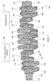
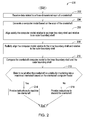
- crankshaft 100 Shown in FIG. 1 is one embodiment of a crankshaft 100 for use in an internal combustion engine, and shown in FIG. 2 is a method 200 for evaluating the crankshaft 100. While the crankshaft 100 is shown as being one for use in a six cylinder internal combustion engine, the method 200 may be used with various sizes and styles of crankshafts.
- the crankshaft 100 may be used in a variety of machines, including on-highway trucks, construction vehicles, marine vessels, stationary generators, automobiles, agricultural tractors, agricultural vehicles, and recreational vehicles.
- the crankshaft 100 includes main journals 104 used as the pivoting links with respect to the crankcase of the engine. Further, the crankshaft 100 includes crankpin journals 110, each of which are shifted in relation to the main journals 104 and each of which link with a connecting rod, and coupled to each connecting rod is a piston for moving in a cylinder.
- the crankpin journals 110 are positioned between the main journals 104 and shifted therefrom by arms 108, ensuring not only their shifting but also their spacing between the main journals 104 and crankpin journals 110.
- the arms 108 include counterweights 106 for balancing the unbalance due to the shifting of the mass of the main journals 104 and crankpin journals 110.
- processing unit 130 may be embodied as part of one or more application-specific integrated circuits (ASICs). Unless otherwise specifically noted, the processing unit 130 is not limited to any specific combination of hardware circuitry and software, nor to any particular source for the instructions executed by the processing unit 130.
- ASICs application-specific integrated circuits
- a computer program means any expression, in any language, code or notation, of a set of instructions intended to cause a system having an information processing capability to perform a particular function either directly or after either or both of the following: a) conversion to another language, code or notation; b) reproduction in a different material form.
- a computer program can include, but is not limited to, a subroutine, a function, a procedure, an object method, an object implementation, an executable application, an applet, a servlet, a source code, an object code, a shared library/dynamic load library and/or other sequence of instructions designed for execution by the processing unit 130.
- the three dimensional scan may be taken by a three dimensional scanner 102 that scans the crankshaft 100.
- the three dimensional scanner 102 may be a device for analyzing an object and for collecting data related to its shape.
- the three dimensional scanner 102 may create a point cloud of geometric samples on the surface of the objects, so that the points can then be used to extrapolate the shape thereof.
- the three dimensional scanner 102 may be a non-contact active scanner, a kind that emits some kind of radiation or light and then detects its reflection or radiation passing through the object.
- the three dimensional scanner 102 may be a non-contact passive scanner, a kind that does not emit any radiation, but instead relies on detecting reflected ambient radiation.
- Some scanners of this kind detect visible light, because it is readily available ambient radiation.
- a non-contact passive scanner is a stereoscopic system, which employs two video cameras spaced apart from one another, so as to look at the same scene from different angles. By analyzing the slight differences between the images, it is possible to determine the distance to each point for reconstructing the object.
- the method 200 may be calculate all places where the crankshaft 100 has material present, in contrast to where it does not (i.e., simply an area surrounding the crankshaft 100).
- the model 300 because it is based on the crankshaft 100, may include modeled main journals 304, modeled counterweights 306, modeled arms 308, modeled crankpin journals 310, a modeled first end 318, and a modeled second end 320.
- the processing unit 130 may axially align the external shell 332 with corresponding sections of an inner boundary shell 430, and additionally it may axially align the external shell 332 with the corresponding sections of an outer boundary shell 432.
- the inner boundary shell 430 represents at least a threshold between a crankshaft comprising an appropriate amount of material and a crankshaft comprising insufficient material.
- the inner boundary shell 430 may be representative of a smallest crankshaft that is still large enough for the crankshaft 100 to be machined into a machined crankshaft capable of meeting design and use requirements related thereto.
- the outer boundary shell 432 may represent at least a threshold between a crankshaft comprising an appropriate amount of material and a crankshaft comprising unwanted material.
- the outer boundary shell 432 may be representative of a largest crankshaft that does not potentially result in damage to machine tools used for machining the crankshaft 100 into the machined crankshaft or excessive machining operations related thereto.
- the processing unit 130 may axially align slices 326 of the external shell 332 with corresponding slices 426 of the inner boundary shell 430 and the outer boundary shell 432.
- a section of the external shell 332 that defines a face of the crankshaft 100 may be axially aligned with corresponding sections of the inner boundary shell 430 and the outer boundary shell 432 that define the same face, for example.
- the face may be a first end 118 or a second end 120 or one of the various other faces of the crankshaft 100.
- a section of the external shell 332 that defines a pair of faces of the crankshaft 100 may be centered relative to corresponding sections of the inner boundary shell 430 that defines the same pair of faces and also centered relative to corresponding sections of the outer boundary shell 432 that also defines the same pair of faces.
- the model 300 may be a three dimensional array, and the inner boundary shell 430 and the outer boundary shell 432 may also be three dimensional arrays, both of which could be aligned with one another. While the face(s) of the crankshaft 100 is used in these illustrative embodiments, other sections of the crankshaft 100 may also be used, using the same general methodology.
- the processing unit 130 may radially align the external shell 332 with the corresponding sections of the inner boundary shell 430, and also may radially align the external shell 332 with corresponding sections of the outer boundary shell 432. In one embodiment of the method 200, at 208, the processing unit 130 may radially align the slices 326 of the external shell 332 with the corresponding slices 426 of the inner boundary shell 430 and the outer boundary shell 432.
- the radial alignment may include aligning a section of the external shell 332 that defines one or more of the crankpin journals 110 with the corresponding section(s) of the inner boundary shell 430 and the outer boundary shell 432.
- the radial alignment may include aligning a section of the external shell 332 defines one or more of the arms 108 (or counterweights 106) with the corresponding section(s) of the inner boundary shell 430 and the outer boundary shell 432.
- the radial alignment may include aligning a section of the external shell 332 of the crankshaft 100 that defines, for example, a face of the crankshaft 100 (e.g., a face of a web) with a corresponding section of the inner boundary shell 430 and the outer boundary shell 432.
- the model 300, the inner boundary shell 430, and the outer boundary shell 432 may be three dimensional arrays, all of which could be aligned with one another, so as to radially align respective features thereof.
- the processing unit 130 compares the model 300 to the inner boundary shell 430 and to the outer boundary shell 432. For example, the processing unit 130 may compare the slices 326 of the external shell 332 to the corresponding slices 426 of the inner boundary shell 430 and the outer boundary shell 432. And at 212, the processing unit 130 determines whether the crankshaft 100 is suitable for machining into the machined crankshaft based on the model 300.
- the crankshaft 100 may be suitable for machining if it has enough material (e.g., robust webs), if it is suitable for a standard set of machining operations without a high risk of damage to the machine tools associated therewith, and/or if it is capable of meeting design and use requirements related thereto.
- the processing unit 130 provides instructions to machine the crankshaft 100 if the determining indicates that the crankshaft 100 is suitable for machining into the machined crankshaft. For example, at 214, the processing unit 130 provides instructions to machine the crankshaft 100 if the comparing indicates that all portions of the external shell 332 are radially outside of the inner boundary shell 430, and/or if the comparing indicates that all portions of the external shell 332 are radially inside of the outer boundary shell 432. Typical machining operations may include broaching, drilling, and grinding techniques.
- the processing unit 130 provides instructions to discard the crankshaft 100 if the determining indicates that the crankshaft 100 comprises insufficient material, or if the crankshaft 100 comprises unwanted material. Discarding the crankshaft 100 may include, for example, recycling it or scrapping it.
- the crankshaft 100 may comprise insufficient material if, for example, it does not have enough material (e.g., weak webs with too little material).
- the crankshaft 100 may comprise unwanted material if a standard set of machining operations cannot be used for machining the crankshaft 100 into the machined crankshaft (e.g., it has extra material that may damage the machine tools).
- the processing unit 130 provides instructions to discard the crankshaft 100 if the comparing indicates that a portion of the external shell 332 is radially inside of the inner boundary shell 430, and/or if a portion of the external shell 332 is radially outside of the outer boundary shell 432.
Landscapes
- Engineering & Computer Science (AREA)
- Physics & Mathematics (AREA)
- General Physics & Mathematics (AREA)
- Automation & Control Theory (AREA)
- Manufacturing & Machinery (AREA)
- Human Computer Interaction (AREA)
- Mechanical Engineering (AREA)
- General Engineering & Computer Science (AREA)
- Optics & Photonics (AREA)
- Theoretical Computer Science (AREA)
- Quality & Reliability (AREA)
- Geometry (AREA)
- Evolutionary Computation (AREA)
- Computer Hardware Design (AREA)
- Shafts, Cranks, Connecting Bars, And Related Bearings (AREA)
- Architecture (AREA)
- Software Systems (AREA)
- General Factory Administration (AREA)
Abstract
Description
- The present disclosure relates to a method for evaluating a crankshaft.
- Reciprocating engines have machined crankshafts that rotate at high speeds, and also have pistons and connecting rods that oscillate up and down with every revolution of the machined crankshaft. These parts are referred to as the engine's rotating assembly. Machined crankshafts need to be highly engineered, so as to maximize the efficiency of the energy conversion process and also to resist shock loading issues and fatigue failure. Further, machined crankshafts need to be light and small, so as to provide fast response times and to be compact enough to fit inside of an engine block.
- Crankshafts may be made by a deformation process in which the work is compressed between a pair of dies, using either impact or gradual pressure to form the part. Over time, the dies change and cause latent changes between (respective) crankshafts. As just one example, when the dies form the crankshaft, there may be a thin web left thereon where the two dies meet. The size of the thin web varies between the crankshafts, as its size is related to how much wear there is on the dies.
- Engine designers specify material distribution in critical areas for ensuring that mechanical material limits of the machined crankshaft are not exceeded. For example, a pin journal of the machined crankshaft transmits energy of the piston through the web of material that joins the pin journal to the main journal. There must be enough material that is properly located in the web for preventing failure thereof. In at least some cases, the web and the pin journals have been identified as the weakest areas of the machined crankshaft. Despite the importance and potential weakness of the web and pin journals, they may be defect prone. The heated steel used to form the crankshaft is subjected to the highest flow rate and restrictions in the pin journal area, resulting in a higher likelihood of die wear in these particular areas and a higher likelihood of improper die fill. Further, the pin journals lie on a parting line where upper and lower dies join together in the forging process, resulting in misplaced material caused by the dies shifting relative to each other or the dies not closing completely.
- One manufacturing method is to visually inspect each crankshaft for issues relating to improper die fill and misplaced material; however, such a method is labor intensive and subject to human error.
- Disclosed is a method for evaluating a crankshaft. The method comprises receiving data related to a three dimensional scan of the crankshaft, generating a crankshaft computer model based on the data, and determining whether the crankshaft is suitable for machining into a machined crankshaft based on the crankshaft computer model.
- The detailed description of the drawings refers to the accompanying figures in which:
- FIG. 1
- is a perspective view of an example crankshaft,
- FIG. 2
- is an example of a method for evaluating the crankshaft,
- FIG. 3
- is an elevational view, illustrating an external shell of a crankshaft computer model being in axial alignment with an inner boundary shell and an outer boundary shell, and
- FIG. 4
- is a cross section of
FIG. 3 taken along lines 4-4, illustrating the external shell of the crankshaft computer model being in radial alignment with the inner boundary shell and the outer boundary shell. - Like reference numerals in the various drawings indicate like elements.
- Shown in
FIG. 1 is one embodiment of acrankshaft 100 for use in an internal combustion engine, and shown inFIG. 2 is amethod 200 for evaluating thecrankshaft 100. While thecrankshaft 100 is shown as being one for use in a six cylinder internal combustion engine, themethod 200 may be used with various sizes and styles of crankshafts. Thecrankshaft 100 may be used in a variety of machines, including on-highway trucks, construction vehicles, marine vessels, stationary generators, automobiles, agricultural tractors, agricultural vehicles, and recreational vehicles. - The
crankshaft 100 includesmain journals 104 used as the pivoting links with respect to the crankcase of the engine. Further, thecrankshaft 100 includescrankpin journals 110, each of which are shifted in relation to themain journals 104 and each of which link with a connecting rod, and coupled to each connecting rod is a piston for moving in a cylinder. Thecrankpin journals 110 are positioned between themain journals 104 and shifted therefrom byarms 108, ensuring not only their shifting but also their spacing between themain journals 104 andcrankpin journals 110. Thearms 108 includecounterweights 106 for balancing the unbalance due to the shifting of the mass of themain journals 104 andcrankpin journals 110. - Referring further to
FIGS. 1 to 2 , at 202, aprocessing unit 130 receives data related to a three dimensional scan of thecrankshaft 100. In an example embodiment, theprocessing unit 130 is a device that executes sequences of instructions, in the form of a computer program, contained in a memory. Execution of the sequences of instructions causes theprocessing unit 130 to perform steps such as generating control signals. The instructions may be loaded in a random access memory (RAM) for execution by theprocessing unit 130 from a read only memory (ROM), a mass storage device, or some other persistent storage. In other embodiments, hard wired circuitry may be used in place of or in combination with software instructions to implement the functions described. For example, theprocessing unit 130 may be embodied as part of one or more application-specific integrated circuits (ASICs). Unless otherwise specifically noted, theprocessing unit 130 is not limited to any specific combination of hardware circuitry and software, nor to any particular source for the instructions executed by theprocessing unit 130. - In an example embodiment, the term "computer program" means any expression, in any language, code or notation, of a set of instructions intended to cause a system having an information processing capability to perform a particular function either directly or after either or both of the following: a) conversion to another language, code or notation; b) reproduction in a different material form. For example, a computer program can include, but is not limited to, a subroutine, a function, a procedure, an object method, an object implementation, an executable application, an applet, a servlet, a source code, an object code, a shared library/dynamic load library and/or other sequence of instructions designed for execution by the
processing unit 130. - The three dimensional scan may be taken by a three
dimensional scanner 102 that scans thecrankshaft 100. The threedimensional scanner 102 may be a device for analyzing an object and for collecting data related to its shape. The threedimensional scanner 102 may create a point cloud of geometric samples on the surface of the objects, so that the points can then be used to extrapolate the shape thereof. The threedimensional scanner 102 may be a non-contact active scanner, a kind that emits some kind of radiation or light and then detects its reflection or radiation passing through the object. As another example, the threedimensional scanner 102 may be a non-contact passive scanner, a kind that does not emit any radiation, but instead relies on detecting reflected ambient radiation. Some scanners of this kind detect visible light, because it is readily available ambient radiation. One example of a non-contact passive scanner is a stereoscopic system, which employs two video cameras spaced apart from one another, so as to look at the same scene from different angles. By analyzing the slight differences between the images, it is possible to determine the distance to each point for reconstructing the object. - Further, at 204, the
processing unit 130 generates acrankshaft computer model 300 based on the scanning of thecrankshaft 100. Themodel 300 may represent at least an external shell 332 of the crankshaft 100 (e.g., the shape of the crankshaft 100). In at least some embodiments of themethod 200, themodel 300 is a three dimensional array. The three dimensional array may be made of a plurality of ones and zeroes, wherein the ones may represent where material of thecrankshaft 100 is present and the zeroes represent where material is not present, for example. This plurality of values may indicate the shape defined by thecrankshaft 100. And by knowing the shape and assuming that it is homogenous, themethod 200 may be calculate all places where thecrankshaft 100 has material present, in contrast to where it does not (i.e., simply an area surrounding the crankshaft 100). Themodel 300, because it is based on thecrankshaft 100, may include modeledmain journals 304, modeledcounterweights 306, modeledarms 308, modeledcrankpin journals 310, a modeledfirst end 318, and a modeledsecond end 320. - At 206, the
processing unit 130 may axially align the external shell 332 with corresponding sections of aninner boundary shell 430, and additionally it may axially align the external shell 332 with the corresponding sections of anouter boundary shell 432. Theinner boundary shell 430 represents at least a threshold between a crankshaft comprising an appropriate amount of material and a crankshaft comprising insufficient material. For example, theinner boundary shell 430 may be representative of a smallest crankshaft that is still large enough for thecrankshaft 100 to be machined into a machined crankshaft capable of meeting design and use requirements related thereto. In contrast, theouter boundary shell 432 may represent at least a threshold between a crankshaft comprising an appropriate amount of material and a crankshaft comprising unwanted material. For example, theouter boundary shell 432 may be representative of a largest crankshaft that does not potentially result in damage to machine tools used for machining thecrankshaft 100 into the machined crankshaft or excessive machining operations related thereto. - At 206, the
processing unit 130 may axially align slices 326 of the external shell 332 with corresponding slices 426 of theinner boundary shell 430 and theouter boundary shell 432. For example, at 206, a section of the external shell 332 that defines a face of thecrankshaft 100 may be axially aligned with corresponding sections of theinner boundary shell 430 and theouter boundary shell 432 that define the same face, for example. The face may be afirst end 118 or asecond end 120 or one of the various other faces of thecrankshaft 100. As another example, a section of the external shell 332 that defines a pair of faces of thecrankshaft 100 may be centered relative to corresponding sections of theinner boundary shell 430 that defines the same pair of faces and also centered relative to corresponding sections of theouter boundary shell 432 that also defines the same pair of faces. In either case, themodel 300 may be a three dimensional array, and theinner boundary shell 430 and theouter boundary shell 432 may also be three dimensional arrays, both of which could be aligned with one another. While the face(s) of thecrankshaft 100 is used in these illustrative embodiments, other sections of thecrankshaft 100 may also be used, using the same general methodology. - At 208, the
processing unit 130 may radially align the external shell 332 with the corresponding sections of theinner boundary shell 430, and also may radially align the external shell 332 with corresponding sections of theouter boundary shell 432. In one embodiment of themethod 200, at 208, theprocessing unit 130 may radially align the slices 326 of the external shell 332 with the corresponding slices 426 of theinner boundary shell 430 and theouter boundary shell 432. - At 208, the radial alignment may include aligning a section of the external shell 332 that defines one or more of the
crankpin journals 110 with the corresponding section(s) of theinner boundary shell 430 and theouter boundary shell 432. As another example, at 208, the radial alignment may include aligning a section of the external shell 332 defines one or more of the arms 108 (or counterweights 106) with the corresponding section(s) of theinner boundary shell 430 and theouter boundary shell 432. And as yet another example, at 208, the radial alignment may include aligning a section of the external shell 332 of thecrankshaft 100 that defines, for example, a face of the crankshaft 100 (e.g., a face of a web) with a corresponding section of theinner boundary shell 430 and theouter boundary shell 432. In all such examples, themodel 300, theinner boundary shell 430, and theouter boundary shell 432 may be three dimensional arrays, all of which could be aligned with one another, so as to radially align respective features thereof. - At 210, the
processing unit 130 compares themodel 300 to theinner boundary shell 430 and to theouter boundary shell 432. For example, theprocessing unit 130 may compare the slices 326 of the external shell 332 to the corresponding slices 426 of theinner boundary shell 430 and theouter boundary shell 432. And at 212, theprocessing unit 130 determines whether thecrankshaft 100 is suitable for machining into the machined crankshaft based on themodel 300. Thecrankshaft 100 may be suitable for machining if it has enough material (e.g., robust webs), if it is suitable for a standard set of machining operations without a high risk of damage to the machine tools associated therewith, and/or if it is capable of meeting design and use requirements related thereto. - At 214, the
processing unit 130 provides instructions to machine thecrankshaft 100 if the determining indicates that thecrankshaft 100 is suitable for machining into the machined crankshaft. For example, at 214, theprocessing unit 130 provides instructions to machine thecrankshaft 100 if the comparing indicates that all portions of the external shell 332 are radially outside of theinner boundary shell 430, and/or if the comparing indicates that all portions of the external shell 332 are radially inside of theouter boundary shell 432. Typical machining operations may include broaching, drilling, and grinding techniques. - At 216, the
processing unit 130 provides instructions to discard thecrankshaft 100 if the determining indicates that thecrankshaft 100 comprises insufficient material, or if thecrankshaft 100 comprises unwanted material. Discarding thecrankshaft 100 may include, for example, recycling it or scrapping it. Thecrankshaft 100 may comprise insufficient material if, for example, it does not have enough material (e.g., weak webs with too little material). Thecrankshaft 100 may comprise unwanted material if a standard set of machining operations cannot be used for machining thecrankshaft 100 into the machined crankshaft (e.g., it has extra material that may damage the machine tools). In one embodiment of themethod 200, at 216, theprocessing unit 130 provides instructions to discard thecrankshaft 100 if the comparing indicates that a portion of the external shell 332 is radially inside of theinner boundary shell 430, and/or if a portion of the external shell 332 is radially outside of theouter boundary shell 432. By discarding thecrankshaft 100 early in the manufacturing process, there may be a considerable decrease in manufacturing costs and an overall increase in production line quality.
Claims (15)
- A method for evaluating a crankshaft, the method comprising the steps (202, 204, 212) of receiving data related to a three dimensional scan of the crankshaft (100); generating a crankshaft computer model (300) based on the data; and determining whether the crankshaft (100) is suitable for machining into a machined crankshaft based on the crankshaft computer model (300).
- The method according to claim 1, characterized by further comprising the step (216) of providing instructions to discard the crankshaft (100) if the step (212) of determining indicates that the crankshaft (100) comprises insufficient material.
- The method according to claim 1, characterized by further comprising the step (216) of providing instructions to discard the crankshaft (100) if the step (212) of determining indicates that the crankshaft (100) comprises unwanted material.
- The method according to claim 1, characterized by further comprising the step (214) of providing instructions to machine the crankshaft (100) if the step (212) of determining indicates that the crankshaft (100) comprises an appropriate amount of material.
- The method according to claim 1, characterized in that the step (212) of determining comprises the step (210) of comparing the crankshaft computer model (300) to an inner boundary shell (430), wherein the crankshaft computer model (300) represents an external shell (332) of the crankshaft (100), and the inner boundary shell (430) represents a threshold between a crankshaft comprising an appropriate amount of material and a crankshaft comprising insufficient material.
- The method according to claim 5, characterized by further comprising the step (214) of providing instructions to machine the crankshaft (100) if the step (210) of comparing indicates that all portions of the external shell (332) are radially outside of the inner boundary shell (430).
- The method according to claim 5, characterized by further comprising the step (214) of providing instructions to discard the crankshaft (100) if the step (210) of comparing indicates that a portion of the external shell (332) is radially inside of the inner boundary shell (430).
- The method according to claim 5, characterized in that the step of comparing comprises the steps (206, 208) of axially and radially aligning the external shell (332) with corresponding sections of the inner boundary shell (430); and the step (210) of comparing the external shell (332) to the corresponding sections of the inner boundary shell (430).
- The method according to claim 1, characterized in that the step (212) of determining comprises the step (210) of comparing the crankshaft computer model (300) to an outer boundary shell (432), wherein the crankshaft computer model (300) represents an external shell (332) of the crankshaft (100), and the outer boundary shell (432) represents a threshold between a crankshaft comprising an appropriate amount of material and a crankshaft comprising unwanted material.
- The method according to claim 9, characterized by further comprising the step (214) of providing instructions to machine the crankshaft (100) if the step (210) of comparing indicates that all portions of the external shell (332) are radially inside of the outer boundary shell (432).
- The method according to claim 9, characterized by further comprising the step (216) of providing instructions to discard the crankshaft (100) if the step (210) of comparing indicates that a portion of the external shell (332) is radially outside of the outer boundary shell.
- The method according to claim 9, characterized in that the step of comparing comprises the steps (206, 208) of axially and radially aligning the external shell (332) with corresponding sections of the outer boundary shell (432); and the step (210) of comparing the external shell (332) to the corresponding sections or the outer boundary shell (432) of the crankshaft (100).
- The method according to claim 1, characterized in that the step (212) of determining comprise the step (210) of comparing the crankshaft computer model (300) to an inner boundary shell (430), wherein the crankshaft computer model (300) represents an external shell (332) of the crankshaft (100), the inner boundary shell (430) represents a threshold between a crankshaft comprising an appropriate amount of material and a crankshaft comprising insufficient material; and the step (210) of comparing the crankshaft computer model (300) to an outer boundary shell (432), wherein the outer boundary shell (432) represents a threshold between the crankshaft comprising the appropriate amount of material and a crankshaft comprising unwanted material.
- The method according to claim 13, characterized by further comprising the step (21) of providing instructions to machine the crankshaft (100) if the step (210) of comparing indicates that all portions of the external shell (332) are radially outside of the inner boundary shell (430) and radially inside of the outer boundary shell (432).
- The method according to claim 13, characterized by further comprising the step (216) of providing instructions to discard the crankshaft (100) if the step (210) of comparing indicates that a portion of the external shell (332) is radially inside of the inner boundary shell (430) or a portion of the external shell (332) is radially outside of the outer boundary shell (432).
Applications Claiming Priority (1)
| Application Number | Priority Date | Filing Date | Title |
|---|---|---|---|
| US14/445,660 US9804585B2 (en) | 2014-07-29 | 2014-07-29 | Computer program and method for evaluating a crankshaft |
Publications (2)
| Publication Number | Publication Date |
|---|---|
| EP2980667A1 true EP2980667A1 (en) | 2016-02-03 |
| EP2980667B1 EP2980667B1 (en) | 2019-01-02 |
Family
ID=53835225
Family Applications (1)
| Application Number | Title | Priority Date | Filing Date |
|---|---|---|---|
| EP15177130.0A Active EP2980667B1 (en) | 2014-07-29 | 2015-07-16 | Method for evaluating a crankshaft |
Country Status (3)
| Country | Link |
|---|---|
| US (1) | US9804585B2 (en) |
| EP (1) | EP2980667B1 (en) |
| CN (1) | CN105320803B (en) |
Cited By (2)
| Publication number | Priority date | Publication date | Assignee | Title |
|---|---|---|---|---|
| CN109035238A (en) * | 2018-08-02 | 2018-12-18 | 哈尔滨工业大学 | A kind of machining allowance off-line analysis method towards Free-form Surface Parts |
| CN110017981A (en) * | 2019-05-24 | 2019-07-16 | 南京林业大学 | Based on the crankshaft fatigue ultimate load prediction technique for improving non-proportional loading model |
Families Citing this family (2)
| Publication number | Priority date | Publication date | Assignee | Title |
|---|---|---|---|---|
| US10047824B2 (en) * | 2014-07-29 | 2018-08-14 | Deere & Company | Method for pre-balancing and machining a crankshaft based on a mass distribution method |
| US10190933B2 (en) * | 2016-11-01 | 2019-01-29 | Dominion Technologies Group, Inc. | Crankshaft balancer machine |
Citations (3)
| Publication number | Priority date | Publication date | Assignee | Title |
|---|---|---|---|---|
| EP1760443A2 (en) * | 2005-08-31 | 2007-03-07 | Société Industrielle et Financière de Courcelles en abrégé "SIFCOR" | Method for dynamic balancing of crankshafts |
| EP2184595A1 (en) * | 2007-08-01 | 2010-05-12 | Komatsu Machinery Corp. | Treating apparatus, center-hole working system, center-hole position deciding program, and center-hole position deciding method |
| US20120259452A1 (en) * | 2010-01-28 | 2012-10-11 | Komatsu Ntc Ltd. | Center hole machining method for shaft blank and center hole machining apparatus |
Family Cites Families (17)
| Publication number | Priority date | Publication date | Assignee | Title |
|---|---|---|---|---|
| DE2823219C2 (en) | 1978-05-27 | 1986-05-28 | Carl Schenck Ag, 6100 Darmstadt | Method and device for centering bodies of revolution provided with uneven mass distribution along their shaft axis |
| DE3662466D1 (en) | 1986-11-26 | 1989-04-20 | Gfm Fertigungstechnik | Method and machine for equilibratingly centering work pieces to be partially cutting-machined, especially crankshafts |
| AU665048B2 (en) | 1992-02-14 | 1995-12-14 | Toyota Jidosha Kabushiki Kaisha | Apparatus and method for feedback-adjusting working condition for improving dimensional accuracy of processed workpieces |
| FR2761129B1 (en) | 1997-03-19 | 1999-06-04 | Renault Automation | PROCESS FOR MACHINING A CRANKSHAFT |
| JP4770542B2 (en) | 2006-03-27 | 2011-09-14 | 日産自動車株式会社 | Rotating body machining center calculation method, rotator machining center calculation program, and rotator machining center calculation device |
| DE102006017232A1 (en) * | 2006-04-12 | 2007-10-25 | Schaeffler Kg | Synchronization device for a motor |
| KR101213551B1 (en) * | 2006-10-18 | 2012-12-18 | 히다치 조센 가부시키가이샤 | Method and device for evaluating shafting alignment of ship |
| CN201077006Y (en) | 2007-08-24 | 2008-06-25 | 湖南大学 | Servo auto-tracing supporting device for crankshaft abrading |
| US7832259B2 (en) * | 2008-06-16 | 2010-11-16 | Gm Global Technology Operations, Inc. | Fuel system diagnostics by analyzing engine crankshaft speed signal |
| JP5135104B2 (en) | 2008-07-30 | 2013-01-30 | コマツNtc株式会社 | Crankshaft center hole determination method and apparatus |
| DE102010003561A1 (en) * | 2010-03-31 | 2011-10-06 | Robert Bosch Gmbh | Method for the systematic treatment of errors |
| US20120037110A1 (en) | 2010-10-26 | 2012-02-16 | Perkins Joseph M | Spin balanced crank assembly |
| CN202008425U (en) | 2011-02-21 | 2011-10-12 | 永安市金声机械有限公司 | Digital display device for crankshaft static balance detection |
| US20120312273A1 (en) * | 2011-06-10 | 2012-12-13 | Robert T. Weverka | Internal combustion engine with torsional element |
| WO2013032431A1 (en) * | 2011-08-29 | 2013-03-07 | Diggs Matthew B | Balanced x - engine assembly |
| DE102011086150B4 (en) * | 2011-11-11 | 2024-03-07 | Robert Bosch Gmbh | Method for operating an internal combustion engine and corresponding computer program, control device and storage medium |
| CN202447712U (en) | 2012-02-14 | 2012-09-26 | 滨州海得曲轴有限责任公司 | Automatic balancing machine special for drilling of center hole |
-
2014
- 2014-07-29 US US14/445,660 patent/US9804585B2/en active Active
-
2015
- 2015-07-16 EP EP15177130.0A patent/EP2980667B1/en active Active
- 2015-07-29 CN CN201510454977.5A patent/CN105320803B/en active Active
Patent Citations (3)
| Publication number | Priority date | Publication date | Assignee | Title |
|---|---|---|---|---|
| EP1760443A2 (en) * | 2005-08-31 | 2007-03-07 | Société Industrielle et Financière de Courcelles en abrégé "SIFCOR" | Method for dynamic balancing of crankshafts |
| EP2184595A1 (en) * | 2007-08-01 | 2010-05-12 | Komatsu Machinery Corp. | Treating apparatus, center-hole working system, center-hole position deciding program, and center-hole position deciding method |
| US20120259452A1 (en) * | 2010-01-28 | 2012-10-11 | Komatsu Ntc Ltd. | Center hole machining method for shaft blank and center hole machining apparatus |
Cited By (4)
| Publication number | Priority date | Publication date | Assignee | Title |
|---|---|---|---|---|
| CN109035238A (en) * | 2018-08-02 | 2018-12-18 | 哈尔滨工业大学 | A kind of machining allowance off-line analysis method towards Free-form Surface Parts |
| CN109035238B (en) * | 2018-08-02 | 2021-09-07 | 哈尔滨工业大学 | An offline analysis method of machining allowance for free-form surface parts |
| CN110017981A (en) * | 2019-05-24 | 2019-07-16 | 南京林业大学 | Based on the crankshaft fatigue ultimate load prediction technique for improving non-proportional loading model |
| CN110017981B (en) * | 2019-05-24 | 2020-12-18 | 南京林业大学 | Crankshaft fatigue limit load prediction method based on improved multiaxial fatigue model |
Also Published As
| Publication number | Publication date |
|---|---|
| US20160033957A1 (en) | 2016-02-04 |
| US9804585B2 (en) | 2017-10-31 |
| CN105320803B (en) | 2021-04-20 |
| CN105320803A (en) | 2016-02-10 |
| EP2980667B1 (en) | 2019-01-02 |
Similar Documents
| Publication | Publication Date | Title |
|---|---|---|
| US10047824B2 (en) | Method for pre-balancing and machining a crankshaft based on a mass distribution method | |
| US9804585B2 (en) | Computer program and method for evaluating a crankshaft | |
| JP6763301B2 (en) | Inspection equipment, inspection methods, inspection processing programs and structure manufacturing methods | |
| US8942837B2 (en) | Method for inspecting a manufacturing device | |
| JP6677161B2 (en) | Measurement processing device, measurement processing method, and measurement processing program | |
| US20200064277A1 (en) | Method of detecting defects in work pieces having curved or cylindrical surfaces | |
| Rudolph et al. | Analysis of design guidelines for automated order acceptance in additive manufacturing | |
| US12547794B2 (en) | Virtual integration test system and method | |
| CN115018772A (en) | Information quantitative defect detection method, image detection device and storage medium | |
| CN116698642A (en) | Work station control method and system for production of automobile repair tool | |
| JP6729652B2 (en) | Measurement processing method, measurement processing apparatus, X-ray inspection apparatus, and structure manufacturing method | |
| US11176660B2 (en) | Sorting pistons with flaws | |
| CN110210110B (en) | A modeling method for process reliability of marine diesel engine fuselage processing | |
| Lawrence. K et al. | An accurate and robust method for the honing angle evaluation of cylinder liner surface using machine vision | |
| Brambilla et al. | Automated vision inspection of critical steel components based on signal analysis extracted form images | |
| CN111151883A (en) | Cylinder liner and piston ring assembly and design method of surface texture | |
| JP2012093200A (en) | Surface evaluation device | |
| CN105964848A (en) | Strengthening method for fillet part of crankshaft and stengthening device therefor | |
| JP2018040739A (en) | Method of inspecting raw materials for internal defects | |
| Mihalache et al. | Experimental framework for FEA analyses of 3D geometry of a connecting rod | |
| US20240161268A1 (en) | Systems and methods for predicting an incoming rotational balance of an unfinished workpiece | |
| Manolescu et al. | Recognizing algorithm for digitized rotational parts | |
| Andrei et al. | Experimental Framework for FEA Analyses of 3D Geometry of a Connecting Rod | |
| JP2007212357A (en) | Shape inspection apparatus, shape inspection system, and shape inspection method | |
| Zeng et al. | Three‐Dimensional Reconstruction of Rolling Contact Fatigue Characteristics |
Legal Events
| Date | Code | Title | Description |
|---|---|---|---|
| PUAI | Public reference made under article 153(3) epc to a published international application that has entered the european phase |
Free format text: ORIGINAL CODE: 0009012 |
|
| AK | Designated contracting states |
Kind code of ref document: A1 Designated state(s): AL AT BE BG CH CY CZ DE DK EE ES FI FR GB GR HR HU IE IS IT LI LT LU LV MC MK MT NL NO PL PT RO RS SE SI SK SM TR |
|
| AX | Request for extension of the european patent |
Extension state: BA ME |
|
| 17P | Request for examination filed |
Effective date: 20160803 |
|
| RBV | Designated contracting states (corrected) |
Designated state(s): AL AT BE BG CH CY CZ DE DK EE ES FI FR GB GR HR HU IE IS IT LI LT LU LV MC MK MT NL NO PL PT RO RS SE SI SK SM TR |
|
| STAA | Information on the status of an ep patent application or granted ep patent |
Free format text: STATUS: EXAMINATION IS IN PROGRESS |
|
| 17Q | First examination report despatched |
Effective date: 20170613 |
|
| GRAP | Despatch of communication of intention to grant a patent |
Free format text: ORIGINAL CODE: EPIDOSNIGR1 |
|
| STAA | Information on the status of an ep patent application or granted ep patent |
Free format text: STATUS: GRANT OF PATENT IS INTENDED |
|
| RIC1 | Information provided on ipc code assigned before grant |
Ipc: G05B 19/418 20060101AFI20180622BHEP Ipc: G06F 17/50 20060101ALI20180622BHEP Ipc: G05B 19/401 20060101ALI20180622BHEP Ipc: G05B 19/18 20060101ALI20180622BHEP Ipc: G05B 19/42 20060101ALI20180622BHEP Ipc: B23Q 17/20 20060101ALI20180622BHEP Ipc: B23Q 17/24 20060101ALI20180622BHEP |
|
| INTG | Intention to grant announced |
Effective date: 20180719 |
|
| GRAS | Grant fee paid |
Free format text: ORIGINAL CODE: EPIDOSNIGR3 |
|
| GRAA | (expected) grant |
Free format text: ORIGINAL CODE: 0009210 |
|
| STAA | Information on the status of an ep patent application or granted ep patent |
Free format text: STATUS: THE PATENT HAS BEEN GRANTED |
|
| AK | Designated contracting states |
Kind code of ref document: B1 Designated state(s): AL AT BE BG CH CY CZ DE DK EE ES FI FR GB GR HR HU IE IS IT LI LT LU LV MC MK MT NL NO PL PT RO RS SE SI SK SM TR |
|
| REG | Reference to a national code |
Ref country code: GB Ref legal event code: FG4D |
|
| REG | Reference to a national code |
Ref country code: CH Ref legal event code: EP Ref country code: AT Ref legal event code: REF Ref document number: 1085178 Country of ref document: AT Kind code of ref document: T Effective date: 20190115 |
|
| REG | Reference to a national code |
Ref country code: IE Ref legal event code: FG4D |
|
| REG | Reference to a national code |
Ref country code: DE Ref legal event code: R096 Ref document number: 602015022625 Country of ref document: DE |
|
| REG | Reference to a national code |
Ref country code: NL Ref legal event code: MP Effective date: 20190102 |
|
| REG | Reference to a national code |
Ref country code: LT Ref legal event code: MG4D |
|
| REG | Reference to a national code |
Ref country code: AT Ref legal event code: MK05 Ref document number: 1085178 Country of ref document: AT Kind code of ref document: T Effective date: 20190102 |
|
| PG25 | Lapsed in a contracting state [announced via postgrant information from national office to epo] |
Ref country code: NL Free format text: LAPSE BECAUSE OF FAILURE TO SUBMIT A TRANSLATION OF THE DESCRIPTION OR TO PAY THE FEE WITHIN THE PRESCRIBED TIME-LIMIT Effective date: 20190102 |
|
| PG25 | Lapsed in a contracting state [announced via postgrant information from national office to epo] |
Ref country code: PT Free format text: LAPSE BECAUSE OF FAILURE TO SUBMIT A TRANSLATION OF THE DESCRIPTION OR TO PAY THE FEE WITHIN THE PRESCRIBED TIME-LIMIT Effective date: 20190502 Ref country code: LT Free format text: LAPSE BECAUSE OF FAILURE TO SUBMIT A TRANSLATION OF THE DESCRIPTION OR TO PAY THE FEE WITHIN THE PRESCRIBED TIME-LIMIT Effective date: 20190102 Ref country code: ES Free format text: LAPSE BECAUSE OF FAILURE TO SUBMIT A TRANSLATION OF THE DESCRIPTION OR TO PAY THE FEE WITHIN THE PRESCRIBED TIME-LIMIT Effective date: 20190102 Ref country code: PL Free format text: LAPSE BECAUSE OF FAILURE TO SUBMIT A TRANSLATION OF THE DESCRIPTION OR TO PAY THE FEE WITHIN THE PRESCRIBED TIME-LIMIT Effective date: 20190102 Ref country code: NO Free format text: LAPSE BECAUSE OF FAILURE TO SUBMIT A TRANSLATION OF THE DESCRIPTION OR TO PAY THE FEE WITHIN THE PRESCRIBED TIME-LIMIT Effective date: 20190402 Ref country code: SE Free format text: LAPSE BECAUSE OF FAILURE TO SUBMIT A TRANSLATION OF THE DESCRIPTION OR TO PAY THE FEE WITHIN THE PRESCRIBED TIME-LIMIT Effective date: 20190102 Ref country code: FI Free format text: LAPSE BECAUSE OF FAILURE TO SUBMIT A TRANSLATION OF THE DESCRIPTION OR TO PAY THE FEE WITHIN THE PRESCRIBED TIME-LIMIT Effective date: 20190102 |
|
| PG25 | Lapsed in a contracting state [announced via postgrant information from national office to epo] |
Ref country code: GR Free format text: LAPSE BECAUSE OF FAILURE TO SUBMIT A TRANSLATION OF THE DESCRIPTION OR TO PAY THE FEE WITHIN THE PRESCRIBED TIME-LIMIT Effective date: 20190403 Ref country code: IS Free format text: LAPSE BECAUSE OF FAILURE TO SUBMIT A TRANSLATION OF THE DESCRIPTION OR TO PAY THE FEE WITHIN THE PRESCRIBED TIME-LIMIT Effective date: 20190502 Ref country code: RS Free format text: LAPSE BECAUSE OF FAILURE TO SUBMIT A TRANSLATION OF THE DESCRIPTION OR TO PAY THE FEE WITHIN THE PRESCRIBED TIME-LIMIT Effective date: 20190102 Ref country code: BG Free format text: LAPSE BECAUSE OF FAILURE TO SUBMIT A TRANSLATION OF THE DESCRIPTION OR TO PAY THE FEE WITHIN THE PRESCRIBED TIME-LIMIT Effective date: 20190402 Ref country code: LV Free format text: LAPSE BECAUSE OF FAILURE TO SUBMIT A TRANSLATION OF THE DESCRIPTION OR TO PAY THE FEE WITHIN THE PRESCRIBED TIME-LIMIT Effective date: 20190102 Ref country code: HR Free format text: LAPSE BECAUSE OF FAILURE TO SUBMIT A TRANSLATION OF THE DESCRIPTION OR TO PAY THE FEE WITHIN THE PRESCRIBED TIME-LIMIT Effective date: 20190102 |
|
| REG | Reference to a national code |
Ref country code: DE Ref legal event code: R097 Ref document number: 602015022625 Country of ref document: DE |
|
| PG25 | Lapsed in a contracting state [announced via postgrant information from national office to epo] |
Ref country code: SK Free format text: LAPSE BECAUSE OF FAILURE TO SUBMIT A TRANSLATION OF THE DESCRIPTION OR TO PAY THE FEE WITHIN THE PRESCRIBED TIME-LIMIT Effective date: 20190102 Ref country code: RO Free format text: LAPSE BECAUSE OF FAILURE TO SUBMIT A TRANSLATION OF THE DESCRIPTION OR TO PAY THE FEE WITHIN THE PRESCRIBED TIME-LIMIT Effective date: 20190102 Ref country code: IT Free format text: LAPSE BECAUSE OF FAILURE TO SUBMIT A TRANSLATION OF THE DESCRIPTION OR TO PAY THE FEE WITHIN THE PRESCRIBED TIME-LIMIT Effective date: 20190102 Ref country code: AL Free format text: LAPSE BECAUSE OF FAILURE TO SUBMIT A TRANSLATION OF THE DESCRIPTION OR TO PAY THE FEE WITHIN THE PRESCRIBED TIME-LIMIT Effective date: 20190102 Ref country code: DK Free format text: LAPSE BECAUSE OF FAILURE TO SUBMIT A TRANSLATION OF THE DESCRIPTION OR TO PAY THE FEE WITHIN THE PRESCRIBED TIME-LIMIT Effective date: 20190102 Ref country code: EE Free format text: LAPSE BECAUSE OF FAILURE TO SUBMIT A TRANSLATION OF THE DESCRIPTION OR TO PAY THE FEE WITHIN THE PRESCRIBED TIME-LIMIT Effective date: 20190102 Ref country code: CZ Free format text: LAPSE BECAUSE OF FAILURE TO SUBMIT A TRANSLATION OF THE DESCRIPTION OR TO PAY THE FEE WITHIN THE PRESCRIBED TIME-LIMIT Effective date: 20190102 Ref country code: AT Free format text: LAPSE BECAUSE OF FAILURE TO SUBMIT A TRANSLATION OF THE DESCRIPTION OR TO PAY THE FEE WITHIN THE PRESCRIBED TIME-LIMIT Effective date: 20190102 |
|
| PLBE | No opposition filed within time limit |
Free format text: ORIGINAL CODE: 0009261 |
|
| STAA | Information on the status of an ep patent application or granted ep patent |
Free format text: STATUS: NO OPPOSITION FILED WITHIN TIME LIMIT |
|
| PG25 | Lapsed in a contracting state [announced via postgrant information from national office to epo] |
Ref country code: SM Free format text: LAPSE BECAUSE OF FAILURE TO SUBMIT A TRANSLATION OF THE DESCRIPTION OR TO PAY THE FEE WITHIN THE PRESCRIBED TIME-LIMIT Effective date: 20190102 |
|
| 26N | No opposition filed |
Effective date: 20191003 |
|
| PG25 | Lapsed in a contracting state [announced via postgrant information from national office to epo] |
Ref country code: SI Free format text: LAPSE BECAUSE OF FAILURE TO SUBMIT A TRANSLATION OF THE DESCRIPTION OR TO PAY THE FEE WITHIN THE PRESCRIBED TIME-LIMIT Effective date: 20190102 Ref country code: MC Free format text: LAPSE BECAUSE OF FAILURE TO SUBMIT A TRANSLATION OF THE DESCRIPTION OR TO PAY THE FEE WITHIN THE PRESCRIBED TIME-LIMIT Effective date: 20190102 |
|
| REG | Reference to a national code |
Ref country code: CH Ref legal event code: PL |
|
| PG25 | Lapsed in a contracting state [announced via postgrant information from national office to epo] |
Ref country code: TR Free format text: LAPSE BECAUSE OF FAILURE TO SUBMIT A TRANSLATION OF THE DESCRIPTION OR TO PAY THE FEE WITHIN THE PRESCRIBED TIME-LIMIT Effective date: 20190102 |
|
| REG | Reference to a national code |
Ref country code: BE Ref legal event code: MM Effective date: 20190731 |
|
| PG25 | Lapsed in a contracting state [announced via postgrant information from national office to epo] |
Ref country code: LI Free format text: LAPSE BECAUSE OF NON-PAYMENT OF DUE FEES Effective date: 20190731 Ref country code: CH Free format text: LAPSE BECAUSE OF NON-PAYMENT OF DUE FEES Effective date: 20190731 Ref country code: LU Free format text: LAPSE BECAUSE OF NON-PAYMENT OF DUE FEES Effective date: 20190716 Ref country code: BE Free format text: LAPSE BECAUSE OF NON-PAYMENT OF DUE FEES Effective date: 20190731 |
|
| PG25 | Lapsed in a contracting state [announced via postgrant information from national office to epo] |
Ref country code: FR Free format text: LAPSE BECAUSE OF NON-PAYMENT OF DUE FEES Effective date: 20190731 |
|
| PG25 | Lapsed in a contracting state [announced via postgrant information from national office to epo] |
Ref country code: IE Free format text: LAPSE BECAUSE OF NON-PAYMENT OF DUE FEES Effective date: 20190716 |
|
| PG25 | Lapsed in a contracting state [announced via postgrant information from national office to epo] |
Ref country code: CY Free format text: LAPSE BECAUSE OF FAILURE TO SUBMIT A TRANSLATION OF THE DESCRIPTION OR TO PAY THE FEE WITHIN THE PRESCRIBED TIME-LIMIT Effective date: 20190102 |
|
| PG25 | Lapsed in a contracting state [announced via postgrant information from national office to epo] |
Ref country code: HU Free format text: LAPSE BECAUSE OF FAILURE TO SUBMIT A TRANSLATION OF THE DESCRIPTION OR TO PAY THE FEE WITHIN THE PRESCRIBED TIME-LIMIT; INVALID AB INITIO Effective date: 20150716 Ref country code: MT Free format text: LAPSE BECAUSE OF FAILURE TO SUBMIT A TRANSLATION OF THE DESCRIPTION OR TO PAY THE FEE WITHIN THE PRESCRIBED TIME-LIMIT Effective date: 20190102 |
|
| PG25 | Lapsed in a contracting state [announced via postgrant information from national office to epo] |
Ref country code: MK Free format text: LAPSE BECAUSE OF FAILURE TO SUBMIT A TRANSLATION OF THE DESCRIPTION OR TO PAY THE FEE WITHIN THE PRESCRIBED TIME-LIMIT Effective date: 20190102 |
|
| PGFP | Annual fee paid to national office [announced via postgrant information from national office to epo] |
Ref country code: DE Payment date: 20250620 Year of fee payment: 11 |
|
| PGFP | Annual fee paid to national office [announced via postgrant information from national office to epo] |
Ref country code: GB Payment date: 20250728 Year of fee payment: 11 |