EP2980552A1 - Method for pre-balancing a crankshaft - Google Patents
Method for pre-balancing a crankshaft Download PDFInfo
- Publication number
- EP2980552A1 EP2980552A1 EP15177123.5A EP15177123A EP2980552A1 EP 2980552 A1 EP2980552 A1 EP 2980552A1 EP 15177123 A EP15177123 A EP 15177123A EP 2980552 A1 EP2980552 A1 EP 2980552A1
- Authority
- EP
- European Patent Office
- Prior art keywords
- model
- crankshaft
- machining
- machined
- longitudinal axis
- Prior art date
- Legal status (The legal status is an assumption and is not a legal conclusion. Google has not performed a legal analysis and makes no representation as to the accuracy of the status listed.)
- Withdrawn
Links
Images



Classifications
-
- F—MECHANICAL ENGINEERING; LIGHTING; HEATING; WEAPONS; BLASTING
- F16—ENGINEERING ELEMENTS AND UNITS; GENERAL MEASURES FOR PRODUCING AND MAINTAINING EFFECTIVE FUNCTIONING OF MACHINES OR INSTALLATIONS; THERMAL INSULATION IN GENERAL
- F16F—SPRINGS; SHOCK-ABSORBERS; MEANS FOR DAMPING VIBRATION
- F16F15/00—Suppression of vibrations in systems; Means or arrangements for avoiding or reducing out-of-balance forces, e.g. due to motion
- F16F15/32—Correcting- or balancing-weights or equivalent means for balancing rotating bodies, e.g. vehicle wheels
- F16F15/322—Correcting- or balancing-weights or equivalent means for balancing rotating bodies, e.g. vehicle wheels the rotating body being a shaft
-
- G—PHYSICS
- G05—CONTROLLING; REGULATING
- G05B—CONTROL OR REGULATING SYSTEMS IN GENERAL; FUNCTIONAL ELEMENTS OF SUCH SYSTEMS; MONITORING OR TESTING ARRANGEMENTS FOR SUCH SYSTEMS OR ELEMENTS
- G05B19/00—Program-control systems
- G05B19/02—Program-control systems electric
- G05B19/18—Numerical control [NC], i.e. automatically operating machines, in particular machine tools, e.g. in a manufacturing environment, so as to execute positioning, movement or co-ordinated operations by means of program data in numerical form
- G05B19/4097—Numerical control [NC], i.e. automatically operating machines, in particular machine tools, e.g. in a manufacturing environment, so as to execute positioning, movement or co-ordinated operations by means of program data in numerical form characterised by using design data to control NC machines, e.g. CAD/CAM
-
- G—PHYSICS
- G01—MEASURING; TESTING
- G01M—TESTING STATIC OR DYNAMIC BALANCE OF MACHINES OR STRUCTURES; TESTING OF STRUCTURES OR APPARATUS, NOT OTHERWISE PROVIDED FOR
- G01M1/00—Testing static or dynamic balance of machines or structures
- G01M1/10—Determining the moment of inertia
-
- G—PHYSICS
- G01—MEASURING; TESTING
- G01M—TESTING STATIC OR DYNAMIC BALANCE OF MACHINES OR STRUCTURES; TESTING OF STRUCTURES OR APPARATUS, NOT OTHERWISE PROVIDED FOR
- G01M1/00—Testing static or dynamic balance of machines or structures
- G01M1/12—Static balancing; Determining position of centre of gravity
-
- G—PHYSICS
- G01—MEASURING; TESTING
- G01M—TESTING STATIC OR DYNAMIC BALANCE OF MACHINES OR STRUCTURES; TESTING OF STRUCTURES OR APPARATUS, NOT OTHERWISE PROVIDED FOR
- G01M1/00—Testing static or dynamic balance of machines or structures
- G01M1/14—Determining imbalance
- G01M1/16—Determining imbalance by oscillating or rotating the body to be tested
- G01M1/24—Performing balancing on elastic shafts, e.g. for crankshafts
-
- G—PHYSICS
- G01—MEASURING; TESTING
- G01M—TESTING STATIC OR DYNAMIC BALANCE OF MACHINES OR STRUCTURES; TESTING OF STRUCTURES OR APPARATUS, NOT OTHERWISE PROVIDED FOR
- G01M1/00—Testing static or dynamic balance of machines or structures
- G01M1/30—Compensating imbalance
- G01M1/34—Compensating imbalance by removing material from the body to be tested, e.g. from the tread of tyres
-
- G—PHYSICS
- G05—CONTROLLING; REGULATING
- G05B—CONTROL OR REGULATING SYSTEMS IN GENERAL; FUNCTIONAL ELEMENTS OF SUCH SYSTEMS; MONITORING OR TESTING ARRANGEMENTS FOR SUCH SYSTEMS OR ELEMENTS
- G05B15/00—Systems controlled by a computer
- G05B15/02—Systems controlled by a computer electric
-
- F—MECHANICAL ENGINEERING; LIGHTING; HEATING; WEAPONS; BLASTING
- F16—ENGINEERING ELEMENTS AND UNITS; GENERAL MEASURES FOR PRODUCING AND MAINTAINING EFFECTIVE FUNCTIONING OF MACHINES OR INSTALLATIONS; THERMAL INSULATION IN GENERAL
- F16C—SHAFTS; FLEXIBLE SHAFTS; ELEMENTS OR CRANKSHAFT MECHANISMS; ROTARY BODIES OTHER THAN GEARING ELEMENTS; BEARINGS
- F16C3/00—Shafts; Axles; Cranks; Eccentrics
- F16C3/04—Crankshafts, eccentric-shafts; Cranks, eccentrics
- F16C3/20—Shape of crankshafts or eccentric-shafts having regard to balancing
-
- G—PHYSICS
- G05—CONTROLLING; REGULATING
- G05B—CONTROL OR REGULATING SYSTEMS IN GENERAL; FUNCTIONAL ELEMENTS OF SUCH SYSTEMS; MONITORING OR TESTING ARRANGEMENTS FOR SUCH SYSTEMS OR ELEMENTS
- G05B2219/00—Program-control systems
- G05B2219/30—Nc systems
- G05B2219/35—Nc in input of data, input till input file format
- G05B2219/35499—Model of process, machine and parameters
Definitions
- the present disclosure relates to a method for pre-balancing a crankshaft.
- Reciprocating engines have machined crankshafts that rotate at high speeds, and also have pistons and connecting rods that oscillate up and down with every revolution of the machined crankshaft. These parts are referred to as the engine's rotating assembly.
- Machined crankshafts need to be highly engineered, so as to maximize the efficiency of the energy conversion process and also to resist shock loading issues and fatigue failure. Further, machined crankshafts need to be light and small, so as to provide fast response times and to be compact enough to fit inside of an engine block.
- the magnitude of the force generated by an unbalance in any given rotating part depends on two things: first, the revolutions per minute ("RPM") of the unbalanced rotating engine part, and second, the level of unbalance.
- RPM revolutions per minute
- the force at the main bearings is proportional to the speed of the engine squared.
- the further the weight creating the unbalance is located from the center of gravity, the greater its effect on the rotating part as the rotating assembly spins.
- large heavy counterweights are used to offset the forces generated by the reciprocating weight of the pistons and rods.
- the machined crankshaft must not only maintain its own balance as it rotates inside the block, but it must also offset the forces generated by the mass of the pistons and rods as they pump up and down.
- crankshafts may be made by a deformation process in which the work is compressed between a pair of dies, using either impact or gradual pressure to form the part. Over time, the dies change and cause latent changes between respective crankshafts.
- the dies when the dies form the crankshaft, there may be a thin web left thereon where the two dies meet. The size of the thin web varies between the crankshafts, as its size is related to how much wear there is on the dies.
- a crankshaft may be pre-balanced by spinning it to check for unbalanced conditions.
- Pre-balancing - or sometimes referred to as rough balancing - is based on a measured unbalanced condition, wherein first and second blind apertures are drilled into both ends of the crankshaft, so as to establish a machining axis for the crankshaft for later broaching, drilling, and grinding processes.
- known manufacturing processes such as spinning processes, are unable to indicate exactly how the mass of the crankshaft is distributed.
- at least some known manufacturing methods are unable to account for the die wear and the associated variations manufactured into each crankshaft (as a result of each crankshaft being unique).
- the proper placement of the machining axis may be critical to both pre-balancing the forged crankshaft and also end-balancing the machined crankshaft. In some cases, if the machining axis is improperly placed, then the machining processes may take too much material off of the forged crankshaft in one or more given places.
- the final, machined crankshaft may still have certain un-machined portions (e.g., the counterweights). The un-machined portions may affect the balance of the final, machined crankshaft and, in some case, so much so that the machined crankshaft cannot be properly balanced and is, thus, scrapped.
- the method includes receiving data related to a three dimensional scan of the crankshaft; generating a model based on the data; and providing instructions, based on the model, for defining a pre-balancing machining axis.
- crankshaft 100 Shown in FIG. 1 is an embodiment of a crankshaft 100, and shown in FIG. 2 is a method 200 for pre-balancing the crankshaft 100 for use in an internal combustion engine. While the crankshaft 100 is shown as being one for use in a six cylinder internal combustion engine, the method 200 may be used with various sizes and styles of crankshafts.
- the crankshaft 100 may be used in a variety of machines, including on-highway trucks, construction vehicles, marine vessels, stationary generators, automobiles, agricultural tractors, agricultural vehicles, and recreational vehicles.
- the crankshaft 100 includes main journals 104 used as the pivoting links with respect to the crankcase of the engine. Further, the crankshaft 100 includes crankpin journals 110, each of which are shifted in relation to the main journals 104 and each of which link with a connecting rod. Coupled to each connecting rod is a piston for moving in a cylinder.
- the crankpin journals 110 are positioned between the main journals 104 and shifted therefrom by arms 108, ensuring not only their shifting but also their spacing between the main journals 104 and crankpin journals 110.
- the arms 108 include counterweights 106 for balancing the unbalance due to the shifting of the mass of the main journals 104 and crankpin journals 110.
- the crankshaft 100 also has a first end 118 and a second end 120. In FIG. 1 , the surfaces of the crankshaft 100 are shown as being rough surfaces, indicative of the crankshaft 100 being un-machined.
- a processing unit 130 receives data related to a three dimensional scan of the crankshaft 100.
- the processing unit 130 is a device that executes sequences of instructions, in the form of a computer program, contained in a memory. Execution of the sequences of instructions causes the processing unit 130 to perform steps such as generating control signals.
- the instructions may be loaded in a random access memory (RAM) for execution by the processing unit 130 from a read only memory (ROM), a mass storage device, or some other persistent storage.
- RAM random access memory
- ROM read only memory
- mass storage device or some other persistent storage.
- hard wired circuitry may be used in place of or in combination with software instructions to implement the functions described.
- processing unit 130 may be embodied as part of one or more application-specific integrated circuits (ASICs). Unless otherwise specifically noted, the processing unit 130 is not limited to any specific combination of hardware circuitry and software, nor to any particular source for the instructions executed by the processing unit 130.
- ASICs application-specific integrated circuits
- a computer program means any expression, in any language, code or notation, of a set of instructions intended to cause a system having an information processing capability to perform a particular function either directly or after either or both of the following: a) conversion to another language, code or notation; b) reproduction in a different material form.
- a computer program may include, but is not limited to, a subroutine, a function, a procedure, an object method, an object implementation, an executable application, an applet, a servlet, a source code, an object code, a shared library/dynamic load library and/or other sequence of instructions designed for execution by the processing unit 130.
- the three dimensional scan may be taken by a three dimensional scanner 102 that scans the crankshaft 100.
- the three dimensional scanner 102 may be a device for analyzing an object and for collecting data related to its shape. For example, the three dimensional scanner 102 may create a point cloud of geometric samples on the surface of the objects, so that the points can then be used to extrapolate the shape thereof.
- the three dimensional scanner 102 may be a non-contact active scanner, a kind that emits some kind of radiation or light and then detects its reflection or radiation passing through the object.
- the three dimensional scanner 102 may be a non-contact passive scanner, a kind that does not emit any kind of radiation, but instead relies on detecting reflected ambient radiation.
- Some scanners of this kind detect visible light, because it is readily available ambient radiation.
- a non-contact passive scanner is a stereoscopic system, which employs two video cameras spaced apart from one another, so as to look at the same scene from different angles. By analyzing the slight differences between the images, it is possible to determine the distance to each point for reconstructing the object.
- the processing unit 130 generates a model 300 that is based on the scanning of the crankshaft 100.
- the model 300 may have a plurality of values indicating whether the crankshaft 100 has material present at each of a plurality of specific locations.
- the model 300 may have a plurality of values indicating the shape defined by an outer shell of the crankshaft 100.
- the model 300 may include modeled main journals 304, modeled counterweights 306, modeled arms 308, modeled crankpin journals 310, a modeled first end 318, and a model second end 320.
- the method 200 may be able to calculate where the crankshaft 100 has material present, in contrast to where it does not (e.g., simply an area surrounding the crankshaft 100).
- the model 300 is shown as being smooth, so as to simplify FIGS. 3 to 5 and so as to better illustrate other features. However, in some embodiments of the method 200, the model 300 may be precise enough that the roughness of the crankshaft 100 is contained therein.
- the model 300 may be a three dimensional array.
- the three dimensional array may be made of a plurality of ones and zeroes, wherein the ones may represent where material is present and the zeroes may represent where material is not present, for example.
- the processing unit 130 defines a temporary longitudinal axis 314 that intersects the model 300.
- the defining may include defining a temporary longitudinal axis 314 that initially intersects a geometric center of the crankshaft 100, wherein the geometric center of the crankshaft 100 may be based on, for example, the geometric center of the modeled main journals 304 (as based on the main journals 104).
- the model 300 may be compared to a machining model 400.
- the machining model 400 which may be a three dimensional array, may have a second plurality of values indicating whether a machining operation is performed at each of a second plurality of specific locations.
- the three dimensional array may be made of a plurality of ones and zeroes, wherein the ones may represent where machining operations would be performed and where zeroes may represent where machining operations would not be performed.
- the machining operations represent where machining operations would take place relative to the crankshaft 100, assuming the machining axis is equivalent to the temporary longitudinal axis 314.
- the machining model 400 may include main journal machining operations 404 and crankpin journal machining operations 410, to provide just a couple of potential examples.
- the machining operations may not all overlap the crankshaft 100. This is because the machining operations may, in some embodiments, go through a predetermined, consistent set of passes, whether the crankshaft 100 is present at a given location or not. In such embodiments, for example, the crankshaft 100 may not be present at a given location because of die changes, but the machining operations may remain the same and make passes, even where the crankshaft 100 is not present. In other embodiments, the machining operations may vary, so as to align with the model 300, resulting in fewer machining passes, for example.
- the processing unit 130 compares the model 300 to the machining model 400, which may include aligning axially a three dimensional representation 322 of the crankshaft 100 defined by the model 300, and a three dimensional representation 422 of the machining operations defined by the machining model 400.
- the aligning axially may include aligning a portion of the three dimensional representation 322 of the crankshaft 100 that defines, for example, a face of the crankshaft 100 with a corresponding portion of the three dimensional representation 422 of the machining operations that defines a machining operation of a face of the crankshaft 100.
- a section of the three dimensional representation 322 of the crankshaft 100 that defines a pair of faces of the crankshaft 100 may be centered relative to a corresponding section of the three dimensional representation 422 of the machining operations of the machining model 400 that defines a pair of faces.
- the model 300 may be a three dimensional array and the machining model 400 may also be a three dimensional array, both of which could be aligned with one another, so as to align axially what is representative of the crankshaft 100 and what is representative of the machining operation related thereto.
- the face may be representative of the first end 118 or the second end 120, for example, or one of the various other faces of the crankshaft 100.
- the comparing of the model 300 to the machining model 400 may include aligning radially the three dimensional representation 322 of the crankshaft 100, defined by the model 300, and the three dimensional representation 422 of the machining operations defined by the machining model 400 (see FIG. 5 ).
- the aligning radially may include aligning a portion of the three dimensional representation 322 of the crankshaft 100 that represents one or more of the crankpin journals 110 with the corresponding portion(s) of the three dimensional representation 422 of the machining operation that defines the machining that correlates to the one or more crankpin journals 110.
- the aligning radially may include aligning a portion of the three dimensional representation 322 of the crankshaft 100 that defines, for example, a crankpin journal 110 of the crankshaft 100 with a corresponding portion of the three dimensional representation 422 of the machining operations.
- the model 300 may be a three dimensional array and the machining model 400 may be a three dimensional array, both of which could be aligned with one another, so as to align radially what is representative of the crankpin journal 110 of the crankshaft 100 and what is representative of the machining operation related thereto. While the face of the crankshaft 100 is used in this illustrative example, other parts of the crankshaft 100 may also be used, using the same general methodology.
- the processing unit 130 may compare slices 326 of the model 300 to corresponding slices 426 of the machining model 400 (only a few illustrative slices 326 and slices 426 are shown in FIG. 4 ).
- the slices 326 of the model 300 may be perpendicular to the temporary longitudinal axis 314 and may be representative of cross sections of the crankshaft 100 (e.g., two dimensional arrays).
- the corresponding slices 426 of the machining model 400 may be perpendicular to the temporary longitudinal axis 314 and may be representative of cross sections of the machining model 400 (e.g., two dimensional arrays).
- the processing unit 130 theoretically machines away portions of the model 300, so as to form a theoretically machined crankshaft. For example, if slices 326 of the model 300 are compared to corresponding slices 426 of the machining model 400, then each slice 326 of the model 300 could be theoretically machined (e.g., theoretically machined so as to remove the overlap between the model 300 and the machining model 400) and the slices of the theoretically machined crankshaft could then be combined so as to form the entire theoretically machined crankshaft.
- the processing unit 130 creates a mass distribution model of the theoretically machined crankshaft relative to the temporary longitudinal axis 314.
- the creating of 216 may include analyzing the mass distribution model based on theoretically machined slices of the theoretically machined crankshaft. Each slice may be perpendicular to the temporary longitudinal axis 314, and each slice may be representative of a cross section of the theoretically machined crankshaft. The act of analyzing may include finding a center of gravity of each slice of the theoretically machined crankshaft relative to the temporary longitudinal axis 314.
- the processing unit 130 determines whether the mass distribution model of the theoretically machined crankshaft is within a pre-set limit.
- the pre-set limit may be associated with, for example, an unbalance condition of no more than plus or minus two ounce-inches for the first end 118 and the second end 120, or even plus or minus one (or lower) ounce-inches for the first end 118 and the second end 120. In some cases, it may be possible to set the pre-set limit so low the final balancing operations are unnecessary (e.g., counterweight drilling operations).
- the processing unit 130 determines that the mass distribution model is not within the pre-set limit, then the method 200 proceeds to 218, wherein a different temporary longitudinal axis 314 is selected.
- the defining of the different choice of the temporary longitudinal axis 314 may include determining where the temporary longitudinal axis 314 may be properly placed based on the act of finding a center of gravity of each slice of the theoretically machined crankshaft. For example, if the mass distribution model indicates that the mass distribution is offset by 3mm from the temporary longitudinal axis 314 by 110°, then the temporary longitudinal axis 314 may be offset 3 mm away from its previous location at 250°. By iteratively doing this, each temporary longitudinal axis 314 may be more appropriately placed and more likely to be within the bounds of the pre-set limit than the previous temporary longitudinal axis 314.
- the processing unit 130 determines that the mass distribution model is within the pre-set limit, then the method 200 proceeds to 222.
- the processing unit 130 provides instructions for defining a pre-balancing machining axis 500 (see FIG. 6 ).
- the pre-balancing machining axis 500 may be defined by a first blind aperture 502 that is machined into the first end 118 of the crankshaft 100 and in which a second blind aperture 504 is machined into the second end 120 of the crankshaft 100.
- the first and second blind apertures 502, 504 are in alignment with the temporary longitudinal axis 314 that was set in the final iteration of the method 200.
- the crankshaft 100 may be machined into a machined crankshaft, using machining operations such as broaching, drilling, and grinding.
- a technical effect of placing the machining axis 500, by using the method 200, may be that the crankshaft 100 is properly machined and that the machined crankshaft is one that can be both pre-balanced and end-balanced. Otherwise, in some instances, there may be a risk of the machining axis 500 being improperly placed, resulting in the machining processes taking too much material off of the crankshaft 100 in one or more given places. This may be the result of the final, machined crankshaft having certain un-machined portions (e.g., the counterweights 106), which may affect the balance of the final, machined crankshaft.
- Another technical effect of some embodiments of method 200 is that the un-machined portions are accounted for, thereby avoiding situations where the crankshaft 100 cannot be properly end-balanced and is, thus, scrapped.
Landscapes
- Physics & Mathematics (AREA)
- General Physics & Mathematics (AREA)
- Engineering & Computer Science (AREA)
- General Engineering & Computer Science (AREA)
- Aviation & Aerospace Engineering (AREA)
- Automation & Control Theory (AREA)
- Mechanical Engineering (AREA)
- Acoustics & Sound (AREA)
- Manufacturing & Machinery (AREA)
- Human Computer Interaction (AREA)
- Shafts, Cranks, Connecting Bars, And Related Bearings (AREA)
- Numerical Control (AREA)
- Testing Of Balance (AREA)
Abstract
Description
- The present disclosure relates to a method for pre-balancing a crankshaft.
- Reciprocating engines have machined crankshafts that rotate at high speeds, and also have pistons and connecting rods that oscillate up and down with every revolution of the machined crankshaft. These parts are referred to as the engine's rotating assembly. Machined crankshafts need to be highly engineered, so as to maximize the efficiency of the energy conversion process and also to resist shock loading issues and fatigue failure. Further, machined crankshafts need to be light and small, so as to provide fast response times and to be compact enough to fit inside of an engine block.
- The magnitude of the force generated by an unbalance in any given rotating part depends on two things: first, the revolutions per minute ("RPM") of the unbalanced rotating engine part, and second, the level of unbalance. The larger and heavier the part and the faster it rotates, the greater the forces generated by any unbalance. With respect to a rotating machined crankshaft, the force at the main bearings is proportional to the speed of the engine squared. And, additionally, the further the weight creating the unbalance is located from the center of gravity, the greater its effect on the rotating part as the rotating assembly spins. Typically, large heavy counterweights are used to offset the forces generated by the reciprocating weight of the pistons and rods. The machined crankshaft must not only maintain its own balance as it rotates inside the block, but it must also offset the forces generated by the mass of the pistons and rods as they pump up and down.
- As just one example, crankshafts may be made by a deformation process in which the work is compressed between a pair of dies, using either impact or gradual pressure to form the part. Over time, the dies change and cause latent changes between respective crankshafts. As just one example, when the dies form the crankshaft, there may be a thin web left thereon where the two dies meet. The size of the thin web varies between the crankshafts, as its size is related to how much wear there is on the dies.
- A crankshaft may be pre-balanced by spinning it to check for unbalanced conditions. Pre-balancing - or sometimes referred to as rough balancing - is based on a measured unbalanced condition, wherein first and second blind apertures are drilled into both ends of the crankshaft, so as to establish a machining axis for the crankshaft for later broaching, drilling, and grinding processes. However, known manufacturing processes, such as spinning processes, are unable to indicate exactly how the mass of the crankshaft is distributed. In particular, at least some known manufacturing methods are unable to account for the die wear and the associated variations manufactured into each crankshaft (as a result of each crankshaft being unique).
- The proper placement of the machining axis may be critical to both pre-balancing the forged crankshaft and also end-balancing the machined crankshaft. In some cases, if the machining axis is improperly placed, then the machining processes may take too much material off of the forged crankshaft in one or more given places. The final, machined crankshaft may still have certain un-machined portions (e.g., the counterweights). The un-machined portions may affect the balance of the final, machined crankshaft and, in some case, so much so that the machined crankshaft cannot be properly balanced and is, thus, scrapped.
- Disclosed is a method for pre-balancing a crankshaft. The method includes receiving data related to a three dimensional scan of the crankshaft; generating a model based on the data; and providing instructions, based on the model, for defining a pre-balancing machining axis.
- The detailed description of the drawings refers to the accompanying figures in which:
- FIG. 1
- is a perspective view of an example of a crankshaft,
- FIG. 2
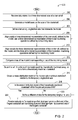
- is an example of a method for pre-balancing the crankshaft,
- FIG. 3
- is a perspective view of an example of a three dimensional representation of the crankshaft defined by a model, and aligned therewith is an example of a three dimensional representation of machining operations defined by a machining model,
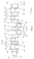
- FIG. 4
- is an elevational view, illustrating the three dimensional representation of the crankshaft being in axial alignment with the three dimensional representation of the machining operations,
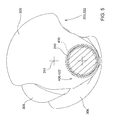
- FIG. 5
- is a cross section of
FIG. 3 taken along lines 5-5, illustrating the three dimensional representation of the crankshaft being in radial alignment with the three dimensional representation of the machining operations, and - FIG. 6
- is a perspective of view of the crankshaft, having a first blind aperture and a second blind aperture machined therein.
- Like reference numerals in the various drawings indicate like elements.
- Shown in
FIG. 1 is an embodiment of acrankshaft 100, and shown inFIG. 2 is amethod 200 for pre-balancing thecrankshaft 100 for use in an internal combustion engine. While thecrankshaft 100 is shown as being one for use in a six cylinder internal combustion engine, themethod 200 may be used with various sizes and styles of crankshafts. Thecrankshaft 100 may be used in a variety of machines, including on-highway trucks, construction vehicles, marine vessels, stationary generators, automobiles, agricultural tractors, agricultural vehicles, and recreational vehicles. - The
crankshaft 100 includesmain journals 104 used as the pivoting links with respect to the crankcase of the engine. Further, thecrankshaft 100 includescrankpin journals 110, each of which are shifted in relation to themain journals 104 and each of which link with a connecting rod. Coupled to each connecting rod is a piston for moving in a cylinder. Thecrankpin journals 110 are positioned between themain journals 104 and shifted therefrom byarms 108, ensuring not only their shifting but also their spacing between themain journals 104 andcrankpin journals 110. Thearms 108 includecounterweights 106 for balancing the unbalance due to the shifting of the mass of themain journals 104 andcrankpin journals 110. Thecrankshaft 100 also has afirst end 118 and asecond end 120. InFIG. 1 , the surfaces of thecrankshaft 100 are shown as being rough surfaces, indicative of thecrankshaft 100 being un-machined. - Referring further to
FIGS. 1 to 2 , at 202, aprocessing unit 130 receives data related to a three dimensional scan of thecrankshaft 100. In an example embodiment, theprocessing unit 130 is a device that executes sequences of instructions, in the form of a computer program, contained in a memory. Execution of the sequences of instructions causes theprocessing unit 130 to perform steps such as generating control signals. The instructions may be loaded in a random access memory (RAM) for execution by theprocessing unit 130 from a read only memory (ROM), a mass storage device, or some other persistent storage. In other embodiments, hard wired circuitry may be used in place of or in combination with software instructions to implement the functions described. For example, theprocessing unit 130 may be embodied as part of one or more application-specific integrated circuits (ASICs). Unless otherwise specifically noted, theprocessing unit 130 is not limited to any specific combination of hardware circuitry and software, nor to any particular source for the instructions executed by theprocessing unit 130. - In an example embodiment, the term "computer program" means any expression, in any language, code or notation, of a set of instructions intended to cause a system having an information processing capability to perform a particular function either directly or after either or both of the following: a) conversion to another language, code or notation; b) reproduction in a different material form. For example, a computer program may include, but is not limited to, a subroutine, a function, a procedure, an object method, an object implementation, an executable application, an applet, a servlet, a source code, an object code, a shared library/dynamic load library and/or other sequence of instructions designed for execution by the
processing unit 130. - The three dimensional scan may be taken by a three
dimensional scanner 102 that scans thecrankshaft 100. The threedimensional scanner 102 may be a device for analyzing an object and for collecting data related to its shape. For example, the threedimensional scanner 102 may create a point cloud of geometric samples on the surface of the objects, so that the points can then be used to extrapolate the shape thereof. The threedimensional scanner 102 may be a non-contact active scanner, a kind that emits some kind of radiation or light and then detects its reflection or radiation passing through the object. As another example, the threedimensional scanner 102 may be a non-contact passive scanner, a kind that does not emit any kind of radiation, but instead relies on detecting reflected ambient radiation. Some scanners of this kind detect visible light, because it is readily available ambient radiation. One example of a non-contact passive scanner is a stereoscopic system, which employs two video cameras spaced apart from one another, so as to look at the same scene from different angles. By analyzing the slight differences between the images, it is possible to determine the distance to each point for reconstructing the object. - Further, at 204, the
processing unit 130 generates a model 300 that is based on the scanning of thecrankshaft 100. The model 300 may have a plurality of values indicating whether thecrankshaft 100 has material present at each of a plurality of specific locations. For example, the model 300 may have a plurality of values indicating the shape defined by an outer shell of thecrankshaft 100. - The model 300, because it is based on the
crankshaft 100, may include modeled main journals 304, modeledcounterweights 306, modeledarms 308, modeledcrankpin journals 310, a modeledfirst end 318, and a modelsecond end 320. By knowing the shape and assuming that the shape is homogenous, themethod 200 may be able to calculate where thecrankshaft 100 has material present, in contrast to where it does not (e.g., simply an area surrounding the crankshaft 100). The model 300 is shown as being smooth, so as to simplifyFIGS. 3 to 5 and so as to better illustrate other features. However, in some embodiments of themethod 200, the model 300 may be precise enough that the roughness of thecrankshaft 100 is contained therein. - In at least some embodiments of
method 200, the model 300 may be a three dimensional array. In such an embodiment, the three dimensional array may be made of a plurality of ones and zeroes, wherein the ones may represent where material is present and the zeroes may represent where material is not present, for example. - At 206, the
processing unit 130 defines a temporarylongitudinal axis 314 that intersects the model 300. The defining may include defining a temporarylongitudinal axis 314 that initially intersects a geometric center of thecrankshaft 100, wherein the geometric center of thecrankshaft 100 may be based on, for example, the geometric center of the modeled main journals 304 (as based on the main journals 104). - The model 300 may be compared to a machining model 400. The machining model 400, which may be a three dimensional array, may have a second plurality of values indicating whether a machining operation is performed at each of a second plurality of specific locations. In such an embodiment, the three dimensional array may be made of a plurality of ones and zeroes, wherein the ones may represent where machining operations would be performed and where zeroes may represent where machining operations would not be performed. The machining operations represent where machining operations would take place relative to the
crankshaft 100, assuming the machining axis is equivalent to the temporarylongitudinal axis 314. The machining model 400 may include mainjournal machining operations 404 and crankpinjournal machining operations 410, to provide just a couple of potential examples. The machining operations may not all overlap thecrankshaft 100. This is because the machining operations may, in some embodiments, go through a predetermined, consistent set of passes, whether thecrankshaft 100 is present at a given location or not. In such embodiments, for example, thecrankshaft 100 may not be present at a given location because of die changes, but the machining operations may remain the same and make passes, even where thecrankshaft 100 is not present. In other embodiments, the machining operations may vary, so as to align with the model 300, resulting in fewer machining passes, for example. - At 210 and as shown in
FIGS. 3 to 4 , theprocessing unit 130 compares the model 300 to the machining model 400, which may include aligning axially a three dimensional representation 322 of thecrankshaft 100 defined by the model 300, and a three dimensional representation 422 of the machining operations defined by the machining model 400. In some embodiments ofmethod 200, at 208, the aligning axially may include aligning a portion of the three dimensional representation 322 of thecrankshaft 100 that defines, for example, a face of thecrankshaft 100 with a corresponding portion of the three dimensional representation 422 of the machining operations that defines a machining operation of a face of thecrankshaft 100. As another example, in some other embodiments, a section of the three dimensional representation 322 of thecrankshaft 100 that defines a pair of faces of thecrankshaft 100 may be centered relative to a corresponding section of the three dimensional representation 422 of the machining operations of the machining model 400 that defines a pair of faces. In either case, the model 300 may be a three dimensional array and the machining model 400 may also be a three dimensional array, both of which could be aligned with one another, so as to align axially what is representative of thecrankshaft 100 and what is representative of the machining operation related thereto. The face may be representative of thefirst end 118 or thesecond end 120, for example, or one of the various other faces of thecrankshaft 100. - At 210, the comparing of the model 300 to the machining model 400 may include aligning radially the three dimensional representation 322 of the
crankshaft 100, defined by the model 300, and the three dimensional representation 422 of the machining operations defined by the machining model 400 (seeFIG. 5 ). As just one example, at 210, the aligning radially may include aligning a portion of the three dimensional representation 322 of thecrankshaft 100 that represents one or more of thecrankpin journals 110 with the corresponding portion(s) of the three dimensional representation 422 of the machining operation that defines the machining that correlates to the one ormore crankpin journals 110. - In some embodiments of
method 200, at 210, the aligning radially may include aligning a portion of the three dimensional representation 322 of thecrankshaft 100 that defines, for example, acrankpin journal 110 of thecrankshaft 100 with a corresponding portion of the three dimensional representation 422 of the machining operations. In such an embodiment, the model 300 may be a three dimensional array and the machining model 400 may be a three dimensional array, both of which could be aligned with one another, so as to align radially what is representative of thecrankpin journal 110 of thecrankshaft 100 and what is representative of the machining operation related thereto. While the face of thecrankshaft 100 is used in this illustrative example, other parts of thecrankshaft 100 may also be used, using the same general methodology. - At 212, the
processing unit 130 may compare slices 326 of the model 300 to corresponding slices 426 of the machining model 400 (only a few illustrative slices 326 and slices 426 are shown inFIG. 4 ). The slices 326 of the model 300 may be perpendicular to the temporarylongitudinal axis 314 and may be representative of cross sections of the crankshaft 100 (e.g., two dimensional arrays). The corresponding slices 426 of the machining model 400 may be perpendicular to the temporarylongitudinal axis 314 and may be representative of cross sections of the machining model 400 (e.g., two dimensional arrays). - At 214, the
processing unit 130 theoretically machines away portions of the model 300, so as to form a theoretically machined crankshaft. For example, if slices 326 of the model 300 are compared to corresponding slices 426 of the machining model 400, then each slice 326 of the model 300 could be theoretically machined (e.g., theoretically machined so as to remove the overlap between the model 300 and the machining model 400) and the slices of the theoretically machined crankshaft could then be combined so as to form the entire theoretically machined crankshaft. - At 216, the
processing unit 130 creates a mass distribution model of the theoretically machined crankshaft relative to the temporarylongitudinal axis 314. In some embodiments of themethod 200, the creating of 216 may include analyzing the mass distribution model based on theoretically machined slices of the theoretically machined crankshaft. Each slice may be perpendicular to the temporarylongitudinal axis 314, and each slice may be representative of a cross section of the theoretically machined crankshaft. The act of analyzing may include finding a center of gravity of each slice of the theoretically machined crankshaft relative to the temporarylongitudinal axis 314. - At 218, the
processing unit 130 determines whether the mass distribution model of the theoretically machined crankshaft is within a pre-set limit. The pre-set limit may be associated with, for example, an unbalance condition of no more than plus or minus two ounce-inches for thefirst end 118 and thesecond end 120, or even plus or minus one (or lower) ounce-inches for thefirst end 118 and thesecond end 120. In some cases, it may be possible to set the pre-set limit so low the final balancing operations are unnecessary (e.g., counterweight drilling operations). - If, at 218, the
processing unit 130 determines that the mass distribution model is not within the pre-set limit, then themethod 200 proceeds to 218, wherein a different temporarylongitudinal axis 314 is selected. Exemplarily, the defining of the different choice of the temporarylongitudinal axis 314 may include determining where the temporarylongitudinal axis 314 may be properly placed based on the act of finding a center of gravity of each slice of the theoretically machined crankshaft. For example, if the mass distribution model indicates that the mass distribution is offset by 3mm from the temporarylongitudinal axis 314 by 110°, then the temporarylongitudinal axis 314 may be offset 3 mm away from its previous location at 250°. By iteratively doing this, each temporarylongitudinal axis 314 may be more appropriately placed and more likely to be within the bounds of the pre-set limit than the previous temporarylongitudinal axis 314. - If, at 218, the
processing unit 130 determines that the mass distribution model is within the pre-set limit, then themethod 200 proceeds to 222. At 222, theprocessing unit 130 provides instructions for defining a pre-balancing machining axis 500 (seeFIG. 6 ). Thepre-balancing machining axis 500 may be defined by a firstblind aperture 502 that is machined into thefirst end 118 of thecrankshaft 100 and in which a secondblind aperture 504 is machined into thesecond end 120 of thecrankshaft 100. The first and secondblind apertures longitudinal axis 314 that was set in the final iteration of themethod 200. Then, based on themachining axis 500 being a centerline, thecrankshaft 100 may be machined into a machined crankshaft, using machining operations such as broaching, drilling, and grinding. - A technical effect of placing the
machining axis 500, by using themethod 200, may be that thecrankshaft 100 is properly machined and that the machined crankshaft is one that can be both pre-balanced and end-balanced. Otherwise, in some instances, there may be a risk of themachining axis 500 being improperly placed, resulting in the machining processes taking too much material off of thecrankshaft 100 in one or more given places. This may be the result of the final, machined crankshaft having certain un-machined portions (e.g., the counterweights 106), which may affect the balance of the final, machined crankshaft. Another technical effect of some embodiments ofmethod 200 is that the un-machined portions are accounted for, thereby avoiding situations where thecrankshaft 100 cannot be properly end-balanced and is, thus, scrapped.
Claims (10)
- A method for pre-balancing a crankshaft, the method (200) comprising the steps (202, 204, 222) of receiving data related to a three dimensional scan of the crankshaft (100); generating a model (300) based on the data; and providing instructions, based on the model (300), for defining a pre-balancing machining axis (500).
- The method according to claim 1, characterized by further comprising the step (206) of defining a temporary longitudinal axis (314) that intersects the model (300).
- The method according to claim 2, characterized by further comprising the step (214) of identifying which portions of the model (300) would be machined away based on a positioning of the temporary longitudinal axis (314), so as to form a theoretically machined crankshaft.
- The method according to claim 3, characterized by further comprising the steps (216, 218) of creating a mass distribution model of the theoretically machined crankshaft relative to the temporary longitudinal axis (314); and determining whether the mass distribution model is within a pre-set limit.
- The method according to claim 4, characterized by further comprising, if the mass distribution model is outside of the pre-set limit, the step (220) of repeating the steps (214, 216, 218) of identifying, creating, and determining with different choices for the temporary longitudinal axis (314) that intersects the model (300) until the mass distribution model is within the pre-set limit.
- The method according to claim 5, characterized in that the step (218) of determining comprises the step of analyzing slices of the theoretically machined crankshaft.
- The method according to claim 6, characterized in that the slices are perpendicular to the temporary longitudinal axis (314), and each slice is representative of a cross section of the theoretically machined crankshaft, and the step of analyzing comprises finding a center of gravity of each slice of the theoretically machined crankshaft relative to the temporary longitudinal axis (314).
- The method according to claim 7, characterized by further comprising the step (212) of comparing the model (300) to a machining model (400), the model (300) having a first plurality of values indicating whether the crankshaft (100) has material present at each of a first plurality of specific locations, the machining model (400) having a second plurality of values indicating whether a machining operation would be performed at each of a second plurality of specific locations, and wherein the step (214) of identifying which portions of the model (300) would be machined away is based on the step (212) of comparing of the model (300) to the machining model (400).
- The method according to claim 8, characterized in that the step (212) of comparing comprises comparing slices (326) of the model (300) to corresponding slices (426) of the machining model (400), the slices (326) of the model (300) are perpendicular to the temporary longitudinal axis (314) and are representative of cross sections of the crankshaft (100), the corresponding slices (426) of the machining model (400) are perpendicular to the temporary longitudinal axis (314) and are representative of cross sections of the machining model (400).
- The method according to claim 8, characterized in that the step (212) of comparing of the model (300) to the machining model (400) comprises the steps (208, 210) of aligning axially a three dimensional representation (322) of the crankshaft (100) defined by the model (300), and a three dimensional representation (422) of the machining operations (404, 410) defined by the machining model (400); and aligning radially the three dimensional representation (322) of the crankshaft (100) defined by the model (300), and the three dimensional representation (422) of the machining operations (404, 410) defined by the machining model (400).
Applications Claiming Priority (1)
| Application Number | Priority Date | Filing Date | Title |
|---|---|---|---|
| US14/445,590 US10047824B2 (en) | 2014-07-29 | 2014-07-29 | Method for pre-balancing and machining a crankshaft based on a mass distribution method |
Publications (1)
| Publication Number | Publication Date |
|---|---|
| EP2980552A1 true EP2980552A1 (en) | 2016-02-03 |
Family
ID=53835224
Family Applications (1)
| Application Number | Title | Priority Date | Filing Date |
|---|---|---|---|
| EP15177123.5A Withdrawn EP2980552A1 (en) | 2014-07-29 | 2015-07-16 | Method for pre-balancing a crankshaft |
Country Status (3)
| Country | Link |
|---|---|
| US (1) | US10047824B2 (en) |
| EP (1) | EP2980552A1 (en) |
| CN (1) | CN105320068B (en) |
Families Citing this family (25)
| Publication number | Priority date | Publication date | Assignee | Title |
|---|---|---|---|---|
| US10190933B2 (en) * | 2016-11-01 | 2019-01-29 | Dominion Technologies Group, Inc. | Crankshaft balancer machine |
| DE102018115363B3 (en) * | 2018-06-26 | 2019-11-07 | Schenck Rotec Gmbh | Method for determining an imbalance of a wave-elastic rotor based on the deflection |
| US10821527B2 (en) * | 2018-10-03 | 2020-11-03 | GM Global Technology Operations LLC | Method of manufacturing a crankshaft |
| DE102019113500B4 (en) * | 2019-05-21 | 2022-10-20 | Brandenburgische Technische Universität Cottbus-Senftenberg | Process for digitally balancing a rotor |
| KR102692125B1 (en) * | 2019-12-03 | 2024-08-05 | 현대자동차 주식회사 | Machining center for processing center groove and center groove processing method of the crankshaft using the same |
| US12111626B2 (en) | 2021-06-16 | 2024-10-08 | Fisher-Rosemount Systems, Inc. | Software defined control system including I/O server services that communicate with containerized services |
| US12449789B2 (en) | 2021-06-16 | 2025-10-21 | Fisher-Rosemount Systems, Inc. | Security services in a software defined control system |
| US11789428B2 (en) | 2021-06-16 | 2023-10-17 | Fisher-Rosemount Systems, Inc. | I/O server services for selecting and utilizing active controller outputs from containerized controller services in a process control environment |
| US12321154B2 (en) | 2021-06-16 | 2025-06-03 | Fisher-Rosemount Systems, Inc. | Systems and methods for associating modules in a software defined control system for industrial process plants |
| US11726933B2 (en) | 2021-06-16 | 2023-08-15 | Fisher-Rosemount Systems, Inc. | I/O server services configured to facilitate control in a process control environment by containerized controller services |
| US12535800B2 (en) | 2021-06-16 | 2026-01-27 | Fisher-Rosemount Systems, Inc. | Systems and methods for dynamically maintained redundancy and load balancing in software defined control systems for industrial process plants |
| US12585237B2 (en) | 2021-06-16 | 2026-03-24 | Fisher-Rosemount Systems, Inc. | Systems and methods for hierarchical organization of software defined process control systems for industrial process plants |
| US11960588B2 (en) | 2021-06-16 | 2024-04-16 | Fisher-Rosemount Systems, Inc | Security services in a software defined control system |
| US12007747B2 (en) | 2021-06-16 | 2024-06-11 | Fisher-Rosemount Systems, Inc. | Software defined process control system and methods for industrial process plants |
| US12417120B2 (en) | 2021-06-16 | 2025-09-16 | Fisher-Rosemount Systems, Inc. | Systems and methods for dynamically maintained redundancy and load balancing in software defined control systems for industrial process plants |
| US12314037B2 (en) | 2021-06-16 | 2025-05-27 | Fisher-Rosemount Systems, Inc | Systems and methods for associating modules in a software defined control system for industrial process plants |
| US12619209B2 (en) | 2021-06-16 | 2026-05-05 | Fisher-Rosemount Systems, Inc. | Utilizing quality-of-service metrics to facilitate transitions between I/O channels for I/O server services |
| US12078977B2 (en) | 2021-06-16 | 2024-09-03 | Fisher-Rosemount Systems, Inc. | Discovery service in a software defined control system |
| US12242245B2 (en) | 2021-06-16 | 2025-03-04 | Fisher-Rosemount Systems, Inc. | Discovery service in a software defined control system |
| US12210329B2 (en) | 2021-06-16 | 2025-01-28 | Fisher-Rosemount Systems, Inc. | Systems and methods for dynamically maintained redundancy and load balancing in software defined control systems for industrial process plants |
| WO2023127200A1 (en) * | 2021-12-28 | 2023-07-06 | 日本製鉄株式会社 | Balance inspection device, balance inspection method, balance-inspected crankshaft, computational processing device, and program |
| EP4559142A1 (en) | 2022-07-18 | 2025-05-28 | Fisher-Rosemount Systems, Inc. | Monitoring and operational functionalities for an enterprise using process control or automation system |
| US12476973B2 (en) | 2022-07-18 | 2025-11-18 | Fisher-Rosemount Systems, Inc. | Authentication/authorization framework for a process control or automation system |
| US12524389B2 (en) | 2022-10-20 | 2026-01-13 | Fisher-Rosemount Systems, Inc. | Enterprise engineering and configuration framework for advanced process control and monitoring systems |
| US12586176B2 (en) | 2022-11-10 | 2026-03-24 | Ford Motor Company | Systems and methods for predicting an incoming rotational balance of an unfinished workpiece |
Citations (3)
| Publication number | Priority date | Publication date | Assignee | Title |
|---|---|---|---|---|
| JP2007264746A (en) * | 2006-03-27 | 2007-10-11 | Nissan Motor Co Ltd | Rotating body machining center calculation method, rotator machining center calculation program, and rotator machining center calculation device |
| EP2184595A1 (en) * | 2007-08-01 | 2010-05-12 | Komatsu Machinery Corp. | Treating apparatus, center-hole working system, center-hole position deciding program, and center-hole position deciding method |
| EP2305420A1 (en) * | 2008-07-30 | 2011-04-06 | Komatsu Machinery Corporation | Method and device for determining center hole of crankshaft |
Family Cites Families (61)
| Publication number | Priority date | Publication date | Assignee | Title |
|---|---|---|---|---|
| US3998054A (en) * | 1975-04-16 | 1976-12-21 | Whitestone Bruce G | Rotary mechanism with improved volume displacement characteristics |
| DE2658970C3 (en) * | 1976-12-24 | 1979-09-20 | Gebr. Heller Maschinenfabrik Gmbh, 7440 Nuertingen | Crankshaft milling machine |
| US4080852A (en) * | 1977-03-07 | 1978-03-28 | Cm Systems, Inc. | Method and apparatus for machining crankshafts |
| AT353073B (en) * | 1978-04-18 | 1979-10-25 | Gfm Fertigungstechnik | METHOD OF MACHINING CRANKSHAFT |
| DE2823219C2 (en) * | 1978-05-27 | 1986-05-28 | Carl Schenck Ag, 6100 Darmstadt | Method and device for centering bodies of revolution provided with uneven mass distribution along their shaft axis |
| AT358361B (en) * | 1979-03-08 | 1980-09-10 | Gfm Fertigungstechnik | METHOD FOR PROCESSING MULTIPLE CRANKED CRANKSHAFT |
| DE2909227A1 (en) * | 1979-03-09 | 1980-10-09 | Deutsche Ind Anlagen Kolb | FITTING ON MACHINE TOOLS |
| IT1120335B (en) * | 1979-04-05 | 1986-03-19 | Finike Italiana Marposs | EQUIPMENT FOR THE CONTROL OF LINEAR DIMENSIONS OF TREES |
| DE2915662C3 (en) * | 1979-04-18 | 1984-08-09 | Gebr. Heller Maschinenfabrik GmbH, 7440 Nürtingen | Crankshaft milling machine |
| DE3171691D1 (en) * | 1981-06-06 | 1985-09-12 | Schenck Ag Carl | Switch for ending the adjustment of a crankshaft at balance centering |
| DE3614227A1 (en) * | 1986-04-26 | 1987-11-05 | Porsche Ag | CRANKSHAFT MADE OF AN IRON METAL MATERIAL FOR LIFTING PISTON MACHINES |
| DE3662466D1 (en) * | 1986-11-26 | 1989-04-20 | Gfm Fertigungstechnik | Method and machine for equilibratingly centering work pieces to be partially cutting-machined, especially crankshafts |
| AT394452B (en) * | 1990-07-13 | 1992-04-10 | Gfm Fertigungstechnik | METHOD FOR BALANCING CENTERING PARTIAL WORKPIECES TO BE MACHINED, IN PARTICULAR CRANKSHAFT |
| WO1993011366A1 (en) * | 1991-12-02 | 1993-06-10 | Caterpillar Inc. | Method of manufacturing a crankshaft |
| DE4202513C2 (en) * | 1992-01-30 | 1997-01-23 | Naxos Union Schleifmittel | Method for grinding crank pin journals and grinding machine for carrying out the method |
| AU665048B2 (en) | 1992-02-14 | 1995-12-14 | Toyota Jidosha Kabushiki Kaisha | Apparatus and method for feedback-adjusting working condition for improving dimensional accuracy of processed workpieces |
| JPH0777242A (en) * | 1993-07-14 | 1995-03-20 | Niyuusutain:Kk | Rotator and machine therewith |
| US5435059A (en) * | 1993-10-18 | 1995-07-25 | Chawla; Mohinder P. | Advance balancing process for crankshaft |
| FI98950C (en) * | 1994-10-06 | 1997-09-10 | Waertsilae Nsd Oy Ab | Method of manufacturing a crankshaft for a multi-cylinder internal combustion engine |
| US5659493A (en) * | 1995-03-03 | 1997-08-19 | Ford Motor Company | Virtual machining techniques for modifying computer models of parts |
| US5743230A (en) * | 1996-02-06 | 1998-04-28 | Honda Giken Kogyo Kabushiki Kaisha | Balancer shaft supporting structure in engine |
| US6237442B1 (en) * | 1996-07-09 | 2001-05-29 | Simpson Industries, Inc. | High value static unbalance-type balance shafts |
| US5857388A (en) * | 1996-07-09 | 1999-01-12 | Simpson Industries, Inc. | Balance shafts having minimal mass |
| JP3646902B2 (en) * | 1996-11-21 | 2005-05-11 | コマツ工機株式会社 | Crankshaft machining equipment |
| FR2761129B1 (en) * | 1997-03-19 | 1999-06-04 | Renault Automation | PROCESS FOR MACHINING A CRANKSHAFT |
| DE19749940C5 (en) * | 1997-11-11 | 2010-05-20 | Boehringer Werkzeugmaschinen Gmbh | Method of use for finishing crankshafts |
| US6765566B1 (en) * | 1998-12-22 | 2004-07-20 | Che-Chih Tsao | Method and apparatus for displaying volumetric 3D images |
| FR2797314B1 (en) * | 1999-08-02 | 2002-03-22 | Renault Automation Comau | PROCESS FOR MACHINING A CRANKSHAFT ORIGINALLY AVAILABLE FOR THE BALANCING OPERATION AND DEVICE FOR IMPLEMENTING THE SAME |
| JP2001187913A (en) * | 1999-12-28 | 2001-07-10 | Yamaha Motor Co Ltd | Engine crankshaft |
| US6772654B1 (en) * | 2000-08-14 | 2004-08-10 | Daniel L. Cobble | Coriolis crankshaft |
| US6415847B1 (en) * | 2000-09-12 | 2002-07-09 | Ford Global Tech, Inc. | Crankshaft casting pattern and method |
| US6772725B2 (en) * | 2001-10-22 | 2004-08-10 | Honda Giken Kabushiki Kaisha | Balance shaft, housing for balance shaft and engine oil return passage |
| EP1602840B1 (en) * | 2004-06-04 | 2011-08-24 | Honda Motor Co., Ltd. | Assembled crankshaft |
| JP4263149B2 (en) * | 2004-08-06 | 2009-05-13 | 本田技研工業株式会社 | Cam phase control device for internal combustion engine |
| AT7885U1 (en) * | 2004-11-08 | 2005-10-17 | Magna Drivetrain Ag & Co Kg | AUSGLEICHSWELLE |
| DE102004057111A1 (en) * | 2004-11-26 | 2006-06-01 | Niles-Simmons Industrieanlagen Gmbh | Method for intermediate machining of waves |
| US7984684B2 (en) * | 2006-10-06 | 2011-07-26 | Mitja Victor Hinderks | Marine hulls and drives |
| CN100504892C (en) * | 2007-04-27 | 2009-06-24 | 四川绵竹鑫坤机械制造有限责任公司 | Crankshaft dynamic balance design method |
| CN201077006Y (en) | 2007-08-24 | 2008-06-25 | 湖南大学 | Servo auto-tracing supporting device for crankshaft abrading |
| US8555756B2 (en) * | 2008-04-21 | 2013-10-15 | Bost Machine Tools Company, S .A. | Machine and method for machining large crankshafts |
| JP5296444B2 (en) * | 2008-07-30 | 2013-09-25 | コマツNtc株式会社 | Crankshaft center hole machining apparatus and machining method |
| CN102365467B (en) * | 2009-03-26 | 2015-04-08 | 本田技研工业株式会社 | Crankshaft and method for manufacturing same |
| JP2011144701A (en) * | 2010-01-12 | 2011-07-28 | Honda Motor Co Ltd | Lubricating oil supply device for internal combustion engine |
| CN102725087B (en) * | 2010-01-28 | 2014-09-03 | 小松Ntc株式会社 | Center hole machining method for shaft blank and center hole machining apparatus |
| JP2012086330A (en) * | 2010-10-22 | 2012-05-10 | Komatsu Ntc Ltd | Centering method and device |
| US20120037110A1 (en) | 2010-10-26 | 2012-02-16 | Perkins Joseph M | Spin balanced crank assembly |
| CN202008425U (en) | 2011-02-21 | 2011-10-12 | 永安市金声机械有限公司 | Digital display device for crankshaft static balance detection |
| DE102011076809B4 (en) * | 2011-05-17 | 2014-06-26 | Erwin Junker Maschinenfabrik Gmbh | METHOD FOR COMPLETE MACHINING OF AT LEAST UNWORKED PULLEYS AND PLANE SHEETS OF FORGED OR CASTED COILS OF A CRANKSHAFT AND PRODUCTION LINE PROVIDED FOR IMPLEMENTING THE PROCESS |
| CN202447712U (en) | 2012-02-14 | 2012-09-26 | 滨州海得曲轴有限责任公司 | Automatic balancing machine special for drilling of center hole |
| US8918994B2 (en) * | 2012-10-17 | 2014-12-30 | Ford Global Technologies, Llc | Balancing a pendulum-absorber crankshaft |
| JP5910480B2 (en) * | 2012-12-12 | 2016-04-27 | マツダ株式会社 | Center hole machining method and machining system for forged rotating body |
| FR3001036B1 (en) * | 2013-01-14 | 2015-02-06 | Videometric | METHOD FOR BALANCING A ROTATING PART TO PRODUCE A ROTARY AND EQUILIBRATED ROTATING PIECE |
| DE102013100899B4 (en) * | 2013-01-29 | 2015-02-26 | Schenck Rotec Gmbh | Method and apparatus for determining a machining axis |
| KR102104840B1 (en) * | 2013-01-31 | 2020-04-27 | 코마츠 엔티씨 가부시끼가이샤 | Crankshaft machining system and crankshaft machining method |
| CN103344385A (en) * | 2013-07-04 | 2013-10-09 | 上海工程技术大学 | Crankshaft dynamic balance acquisition method based on finite elements |
| EP2886829A1 (en) * | 2013-12-20 | 2015-06-24 | Hvd Ag | Reciprocating piston engine |
| JP6077483B2 (en) * | 2014-03-26 | 2017-02-08 | 本田技研工業株式会社 | Control device |
| US9341230B2 (en) * | 2014-03-27 | 2016-05-17 | Gardner Denver Petroleum Pumps, Llc | Tunnel-style crankshaft with counterweights of increased radial profile |
| US9804585B2 (en) * | 2014-07-29 | 2017-10-31 | Deere & Company | Computer program and method for evaluating a crankshaft |
| WO2016035148A1 (en) * | 2014-09-02 | 2016-03-10 | 株式会社ニコン | Measurement processing device, x-ray inspection apparatus, method for manufacturing structure, measurement processing method, x-ray inspection method, measurement processing program, and x-ray inspection program |
| JP6763301B2 (en) * | 2014-09-02 | 2020-09-30 | 株式会社ニコン | Inspection equipment, inspection methods, inspection processing programs and structure manufacturing methods |
-
2014
- 2014-07-29 US US14/445,590 patent/US10047824B2/en active Active
-
2015
- 2015-07-16 EP EP15177123.5A patent/EP2980552A1/en not_active Withdrawn
- 2015-07-29 CN CN201510455701.9A patent/CN105320068B/en active Active
Patent Citations (3)
| Publication number | Priority date | Publication date | Assignee | Title |
|---|---|---|---|---|
| JP2007264746A (en) * | 2006-03-27 | 2007-10-11 | Nissan Motor Co Ltd | Rotating body machining center calculation method, rotator machining center calculation program, and rotator machining center calculation device |
| EP2184595A1 (en) * | 2007-08-01 | 2010-05-12 | Komatsu Machinery Corp. | Treating apparatus, center-hole working system, center-hole position deciding program, and center-hole position deciding method |
| EP2305420A1 (en) * | 2008-07-30 | 2011-04-06 | Komatsu Machinery Corporation | Method and device for determining center hole of crankshaft |
Also Published As
| Publication number | Publication date |
|---|---|
| CN105320068B (en) | 2020-11-20 |
| US10047824B2 (en) | 2018-08-14 |
| CN105320068A (en) | 2016-02-10 |
| US20160033006A1 (en) | 2016-02-04 |
Similar Documents
| Publication | Publication Date | Title |
|---|---|---|
| US10047824B2 (en) | Method for pre-balancing and machining a crankshaft based on a mass distribution method | |
| Fonte et al. | Failure mode analysis of two crankshafts of a single cylinder diesel engine | |
| US20200064277A1 (en) | Method of detecting defects in work pieces having curved or cylindrical surfaces | |
| US9539651B2 (en) | Method for machining center holes of forged rotary body and system for machining center holes of forged rotary body | |
| EP2980667B1 (en) | Method for evaluating a crankshaft | |
| US8918994B2 (en) | Balancing a pendulum-absorber crankshaft | |
| US7187436B2 (en) | Multi-resolution inspection system and method of operating same | |
| Thejasree et al. | Modelling and Analysis of Crankshaft for passenger car using ANSYS | |
| Kerst et al. | A semi-analytical bearing model considering outer race flexibility for model based bearing load monitoring | |
| Metkar et al. | A fatigue analysis and life estimation of crankshaft-a review | |
| Vijaykumar et al. | Crankshaft design optimization to improve dynamic balancing and fatigue strength | |
| Solanki et al. | Crankshaft design and optimization-a review | |
| JP4723202B2 (en) | Displacement analysis method and displacement analysis system for rolling bearing | |
| Jayanthan et al. | Fatigue life and stress analysis of a single cylinder four stroke crankshaft | |
| CN111151883A (en) | Cylinder liner and piston ring assembly and design method of surface texture | |
| CN117951829A (en) | Method and device for determining engine crankshaft parameters | |
| JPH05172682A (en) | Device for estimating unbalance of crankshaft | |
| JP7688297B2 (en) | BALANCE INSPECTION DEVICE, BALANCE INSPECTION METHOD, COMPUTING DEVICE, AND PROGRAM | |
| Samavatian et al. | Nonlinear modeling for bearing fault diagnosis in non-stationary operating conditions | |
| Khuanlieng et al. | Broken engine’s crankshaft misalignment inspection by using reverse engineering technique | |
| Karimaei et al. | Effects of bearing steps on probable wear damage of main bearings of an IC engine | |
| Navathale et al. | A Review on Finite Element Analysis of the Crankshaft of Internal Combustion Engine | |
| Cakmak et al. | A dynamic model of an overhung rotor with ball bearings | |
| Baqersad et al. | Full-field strain monitoring of a wind turbine using very limited set of displacements measured with three-dimensional point tracking | |
| Li et al. | Lubrication characteristics study of main bearings on crankshaft balance rate |
Legal Events
| Date | Code | Title | Description |
|---|---|---|---|
| PUAI | Public reference made under article 153(3) epc to a published international application that has entered the european phase |
Free format text: ORIGINAL CODE: 0009012 |
|
| AK | Designated contracting states |
Kind code of ref document: A1 Designated state(s): AL AT BE BG CH CY CZ DE DK EE ES FI FR GB GR HR HU IE IS IT LI LT LU LV MC MK MT NL NO PL PT RO RS SE SI SK SM TR |
|
| AX | Request for extension of the european patent |
Extension state: BA ME |
|
| 17P | Request for examination filed |
Effective date: 20160803 |
|
| RBV | Designated contracting states (corrected) |
Designated state(s): AL AT BE BG CH CY CZ DE DK EE ES FI FR GB GR HR HU IE IS IT LI LT LU LV MC MK MT NL NO PL PT RO RS SE SI SK SM TR |
|
| STAA | Information on the status of an ep patent application or granted ep patent |
Free format text: STATUS: THE APPLICATION IS DEEMED TO BE WITHDRAWN |
|
| 18D | Application deemed to be withdrawn |
Effective date: 20160804 |