EP2980438A1 - Gas-operated spring - Google Patents
Gas-operated spring Download PDFInfo
- Publication number
- EP2980438A1 EP2980438A1 EP15178343.8A EP15178343A EP2980438A1 EP 2980438 A1 EP2980438 A1 EP 2980438A1 EP 15178343 A EP15178343 A EP 15178343A EP 2980438 A1 EP2980438 A1 EP 2980438A1
- Authority
- EP
- European Patent Office
- Prior art keywords
- gas
- annular
- piston rod
- jacket
- overtravel
- Prior art date
- Legal status (The legal status is an assumption and is not a legal conclusion. Google has not performed a legal analysis and makes no representation as to the accuracy of the status listed.)
- Granted
Links
Images

Classifications
-
- F—MECHANICAL ENGINEERING; LIGHTING; HEATING; WEAPONS; BLASTING
- F16—ENGINEERING ELEMENTS AND UNITS; GENERAL MEASURES FOR PRODUCING AND MAINTAINING EFFECTIVE FUNCTIONING OF MACHINES OR INSTALLATIONS; THERMAL INSULATION IN GENERAL
- F16F—SPRINGS; SHOCK-ABSORBERS; MEANS FOR DAMPING VIBRATION
- F16F9/00—Springs, vibration-dampers, shock-absorbers, or similarly-constructed movement-dampers using a fluid or the equivalent as damping medium
- F16F9/02—Springs, vibration-dampers, shock-absorbers, or similarly-constructed movement-dampers using a fluid or the equivalent as damping medium using gas only or vacuum
- F16F9/0209—Telescopic
- F16F9/0218—Mono-tubular units
-
- F—MECHANICAL ENGINEERING; LIGHTING; HEATING; WEAPONS; BLASTING
- F16—ENGINEERING ELEMENTS AND UNITS; GENERAL MEASURES FOR PRODUCING AND MAINTAINING EFFECTIVE FUNCTIONING OF MACHINES OR INSTALLATIONS; THERMAL INSULATION IN GENERAL
- F16F—SPRINGS; SHOCK-ABSORBERS; MEANS FOR DAMPING VIBRATION
- F16F2230/00—Purpose; Design features
- F16F2230/0047—Measuring, indicating
Definitions
- the present invention relates to a gas-operated spring.
- Gas-operated springs are usually defined by a tubular gas containment jacket, which is closed hermetically at one end by an end face provided with a valve for charging with gas, and at the other end by a head portion, which is perforated for the passage of a rod of a piston, which translates inside the jacket; the jacket, the end face and the head portion define the travel space for the piston, while said piston, with the jacket and the end face, defines the gas compression and expansion chamber.
- Such gas-operated springs are typically, but not exclusively, also used in situations, such as in the use of mold dies, mold presses, and the like, in which they can be subjected to situations of high internal pressure or of impact with the associated parts of a press or of a mold die, such that they are susceptible of being damaged; such damage can render the gas-operated spring unusable, making replacement necessary and entailing the shutdown of the machine or plant in which it is deployed to operate, but such damage can also be such as to cause harm to an operator who happens to be in the vicinity, such as in the event of an explosion owing to an uncontrolled increase in the pressure, or in the event of an explosion owing to damage of the piston-rod or of the parts that retain it inside the jacket, or in the event of breakage with uncontrolled outflow of pressurized gas.
- Such 'overtravel' can be caused for example by an unexpected increase of travel on the rod of the spring, which forces the rod to re-enter the body of the spring for an unestimated length, thus generating an 'overtravel' which cannot be supported by the overall structure of the spring.
- the spring can thus 'belly' or split open, or it can break at the points where the parts that go to make it up are joined together, or the sealing elements can give way; in all these cases the result can be an unexpected, unwanted, and dangerous rapid outflow of gas.
- gas-operated springs which comprise safety devices adapted for the controlled outflow, in safety, of the pressurized gas in the event of overtravel.
- Such a gas-operated spring is disclosed and claimed, for example, in EPA 2406520 by SPECIAL SPRINGS S.R.L., with a priority date of March 10, 2009.
- Such gas-operated spring with overtravel safety device comprises a tubular gas containment jacket, which is hermetically closed at one end by an end face and at the other end by a head portion, which is perforated for the passage of a rod of a piston; the jacket, the end face and the piston define the gas compression and expansion chamber; the gas-operated spring is characterized in that it has, on the inner face of the jacket, in the compression chamber, at least one region in low relief which is designed to break the seal provided by the sealing means which are associated either with the piston or with the head portion, and which operate against the inner face of the jacket; such low relief region is provided in a position that is such as to define the limit of travel of the retracting stroke of said piston or of said head portion.
- Such gas-operated spring with overtravel device though working very well and being widely appreciated on the market, has an aspect that can be improved, linked to the visibility of the fact that the overtravel device has come into play.
- the spring may appear to be in perfectly good condition, but part of the gas has escaped in a controlled manner and as a consequence the operation of the spring is no longer what is expected of it.
- the aim of the present invention is to provide a gas-operated spring which is capable of overcoming the above mentioned limitation of conventional gas-operated springs.
- an object of the invention is to provide a gas-operated spring in which it can be clearly perceived that the overtravel safety device has come into play.
- Another object of the invention is to provide a gas-operated spring which enables a user to rapidly restore a die or other machine in which the gas-operated spring is deployed to full efficiency.
- Another object of the invention is to provide a gas-operated spring the functionality of which is not lower than conventional gas-operated springs.
- a gas-operated spring that comprises:
- a gas-operated spring according to the invention is generally designated with the reference numeral 10.
- Such gas-operated spring 10 is of the type comprising:
- a chamber 15 for pressurized gas is defined between the tubular jacket 11, the end face 12, the annular passage portion 13 for a piston rod 14, and the piston rod 14.
- the gas-operated spring 10 also comprises an overtravel safety device 16.
- the peculiarity of the invention lies in that it comprises means 17 for clearly indicating that overtravel for the piston rod 14 has occurred.
- the overtravel safety device 16 comprises:
- the region in low relief 25 is provided, for example, by an annular recess.
- the means 17 for clearly indicating that overtravel has occurred are constituted, in the embodiment described herein by way of non-limiting example of the invention, by a plastically deformable ring 35 which is fixed between the annular safety body 18 and the inner rim 27 of the mouth 28 of the tubular jacket 11 into which the annular safety body 18 is inserted.
- the plastically deformable ring 35 is usually arranged with one of its portions outside the tubular jacket 11.
- the plastically deformable ring 35 comprises an external perimetric flap 29 for resting on the rim 27, and an internal annular rib 30 for interlocking in a corresponding annular seat 31 which is defined on the outer surface of the annular safety body 18.
- the fixing of the plastically deformable ring 35 is provided by way of fastening a raised portion protruding from the annular body 18 inside a complementarily shaped seat defined on the plastically deformable ring 35.
- the fixing of the plastically deformable ring 35 is achieved by interference of such plastically deformable ring 35 with the annular body 18, or between the annular body 18 and the rim 27 of the tubular jacket 11.
- the plastically deformable ring 35 is made of plastic material, or of another plastically deformable or breakable material.
- Operation of the gas-operated spring 10 according to the invention is the following.
- a post 40 for example of a press, shown schematically in Figure 2 , descends until it comes into contact with the annular safety body 18, propelling it, together with the piston rod 14, inside the tubular jacket 11 from which it protrudes by the extent 19.
- the external perimetric flap 29 can be broken.
- Another object of the invention is a gas-operated spring with no overtravel safety device and provided with means of clearly indicating that overtravel of the piston rod has occurred.
- Such gas-operated spring 10 makes it possible for a user to rapidly restore to full efficiency a die or other press machine in which the gas-operated spring is deployed, by replacing the gas-operated spring.
Landscapes
- Engineering & Computer Science (AREA)
- General Engineering & Computer Science (AREA)
- Mechanical Engineering (AREA)
- Fluid-Damping Devices (AREA)
- Presses And Accessory Devices Thereof (AREA)
- Control Of Presses (AREA)
Abstract
- a tubular containment jacket (11),
- an end face (12),
- an opposite annular portion (13) for closing the tubular jacket and for the passage of a piston rod (14),
- a piston rod (14) arranged so as to pass through the annular portion (13),
a chamber for pressurized gas (15) being defined between the tubular jacket, the end face, the annular portion and the piston rod, the gas-operated spring (10) comprising means (17) for clearly indicating that overtravel for the piston rod (14) has occurred.
Description
- The present invention relates to a gas-operated spring.
- Gas-operated springs are usually defined by a tubular gas containment jacket, which is closed hermetically at one end by an end face provided with a valve for charging with gas, and at the other end by a head portion, which is perforated for the passage of a rod of a piston, which translates inside the jacket; the jacket, the end face and the head portion define the travel space for the piston, while said piston, with the jacket and the end face, defines the gas compression and expansion chamber.
- Such gas-operated springs are typically, but not exclusively, also used in situations, such as in the use of mold dies, mold presses, and the like, in which they can be subjected to situations of high internal pressure or of impact with the associated parts of a press or of a mold die, such that they are susceptible of being damaged; such damage can render the gas-operated spring unusable, making replacement necessary and entailing the shutdown of the machine or plant in which it is deployed to operate, but such damage can also be such as to cause harm to an operator who happens to be in the vicinity, such as in the event of an explosion owing to an uncontrolled increase in the pressure, or in the event of an explosion owing to damage of the piston-rod or of the parts that retain it inside the jacket, or in the event of breakage with uncontrolled outflow of pressurized gas.
- One of the foremost reasons that lead to such damage is what is known as 'overtravel' of the piston, i.e. a retracting stroke of the piston rod which is greater than the permitted stroke which that specific gas-operated spring is built to handle.
- Such 'overtravel' can be caused for example by an unexpected increase of travel on the rod of the spring, which forces the rod to re-enter the body of the spring for an unestimated length, thus generating an 'overtravel' which cannot be supported by the overall structure of the spring.
- The spring can thus 'belly' or split open, or it can break at the points where the parts that go to make it up are joined together, or the sealing elements can give way; in all these cases the result can be an unexpected, unwanted, and dangerous rapid outflow of gas.
- In order to prevent such dangerous overtravel situations from happening, gas-operated springs have been devised which comprise safety devices adapted for the controlled outflow, in safety, of the pressurized gas in the event of overtravel.
- Such a gas-operated spring is disclosed and claimed, for example, in EPA 2406520 by SPECIAL SPRINGS S.R.L., with a priority date of March 10, 2009.
- Such gas-operated spring with overtravel safety device comprises a tubular gas containment jacket, which is hermetically closed at one end by an end face and at the other end by a head portion, which is perforated for the passage of a rod of a piston; the jacket, the end face and the piston define the gas compression and expansion chamber; the gas-operated spring is characterized in that it has, on the inner face of the jacket, in the compression chamber, at least one region in low relief which is designed to break the seal provided by the sealing means which are associated either with the piston or with the head portion, and which operate against the inner face of the jacket; such low relief region is provided in a position that is such as to define the limit of travel of the retracting stroke of said piston or of said head portion.
- Such gas-operated spring with overtravel device, though working very well and being widely appreciated on the market, has an aspect that can be improved, linked to the visibility of the fact that the overtravel device has come into play.
- In fact, if an overtravel situation has occurred, the spring may appear to be in perfectly good condition, but part of the gas has escaped in a controlled manner and as a consequence the operation of the spring is no longer what is expected of it.
- The outflow of gas from the spring, owing to the intervention of the safety device against the overtravel of the piston rod, cannot be perceived and the poor operation of a partially discharged gas-operated spring will be evident only when a product that is output from a die or from a press in which such a gas-operated spring is deployed fails to meet the design specifications.
- The aim of the present invention is to provide a gas-operated spring which is capable of overcoming the above mentioned limitation of conventional gas-operated springs.
- Within this aim, an object of the invention is to provide a gas-operated spring in which it can be clearly perceived that the overtravel safety device has come into play.
- Another object of the invention is to provide a gas-operated spring which enables a user to rapidly restore a die or other machine in which the gas-operated spring is deployed to full efficiency.
- Another object of the invention is to provide a gas-operated spring the functionality of which is not lower than conventional gas-operated springs.
- This aim and these and other objects which will become better evident hereinafter are achieved by a gas-operated spring that comprises:
- a tubular containment jacket,
- an end face,
- an opposite annular portion for closing said tubular jacket and for the passage of a piston rod,
- a piston rod arranged so as to pass through said annular portion,
- Further characteristics and advantages of the invention will become better apparent from the detailed description that follows of a preferred, but not exclusive, embodiment of the gas-operated spring according to the invention, which is illustrated for the purposes of non-limiting example in the accompanying drawings wherein:
-
Figure 1 is a perspective view of a gas-operated spring according to the invention; -
Figure 2 is a sectional side view of the gas-operated spring inFigure 1 ; -
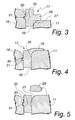
Figure 3 is a detail ofFigure 1 , in a normal configuration of use; -
Figure 4 is the detail inFigure 3 in a first deformed configuration; -
Figure 5 is the detail inFigures 3 and 4 after breakage has occurred. - With reference to the figures, a gas-operated spring according to the invention is generally designated with the
reference numeral 10. - Such gas-operated
spring 10 is of the type comprising: - a
tubular containment jacket 11, - an
end face 12, - an opposite
annular portion 13 for closing thetubular jacket 11 and for the passage of apiston rod 14, - a
piston rod 14 arranged so as to pass through theannular portion 13. - A
chamber 15 for pressurized gas is defined between thetubular jacket 11, theend face 12, theannular passage portion 13 for apiston rod 14, and thepiston rod 14. - In the present embodiment of the invention, which should be understood to be non-limiting, the gas-operated
spring 10 also comprises anovertravel safety device 16. - The peculiarity of the invention lies in that it comprises means 17 for clearly indicating that overtravel for the
piston rod 14 has occurred. - In particular, in the present embodiment described herein by way of non-limiting example of the invention, the
overtravel safety device 16 comprises: - an
annular safety body 18, which defines the opposite passage portion for thepiston rod 14, arranged in thejacket 11 so as to protrude from it by anovertravel safety extent 19 and coupled to thejacket 11 with extraction-preventing means, for example ametallic ring 20 adapted to abut against afirst shoulder 21 defined on theinner surface 22 of thejacket 11 and a second,opposite shoulder 23 defined on theannular safety body 18; suchannular safety body 18 having at least onesealing ring 24 pressed against theinner surface 22 of thetubular jacket 11;. - at least one region in
low relief 25, designed to break the seal of the sealingring 24 when the sealingring 24 is arranged thereat; thelow relief region 25 is provided in such a position as to define the limit of the retracting stroke of theannular safety body 18. - The region in
low relief 25 is provided, for example, by an annular recess. - The
means 17 for clearly indicating that overtravel has occurred are constituted, in the embodiment described herein by way of non-limiting example of the invention, by a plasticallydeformable ring 35 which is fixed between theannular safety body 18 and theinner rim 27 of themouth 28 of thetubular jacket 11 into which theannular safety body 18 is inserted. - The plastically
deformable ring 35 is usually arranged with one of its portions outside thetubular jacket 11. - In the present embodiment, the plastically
deformable ring 35, a cross-section of which is clearly visible inFigure 3 , comprises an externalperimetric flap 29 for resting on therim 27, and an internalannular rib 30 for interlocking in a correspondingannular seat 31 which is defined on the outer surface of theannular safety body 18. - In a variation of embodiment, not shown for the sake of simplicity and understood to be equivalent to what is described above, the fixing of the plastically
deformable ring 35 is provided by way of fastening a raised portion protruding from theannular body 18 inside a complementarily shaped seat defined on the plasticallydeformable ring 35. - In a further variation of embodiment, also not shown, the fixing of the plastically
deformable ring 35 is achieved by interference of such plasticallydeformable ring 35 with theannular body 18, or between theannular body 18 and therim 27 of thetubular jacket 11. - The plastically
deformable ring 35 is made of plastic material, or of another plastically deformable or breakable material. - Operation of the gas-operated
spring 10 according to the invention is the following. - In the event of overtravel, a
post 40, for example of a press, shown schematically inFigure 2 , descends until it comes into contact with theannular safety body 18, propelling it, together with thepiston rod 14, inside thetubular jacket 11 from which it protrudes by theextent 19. - The translation of the
annular safety body 18 inward of thejacket 11 produces the movement of thesealing ring 24 so as to affect thelow relief region 25, with consequent separation of thesealing ring 24 from theinner surface 22 of thetubular jacket 11 and consequent creation of outward escape routes for the gas from thechamber 15. - At the same time, the movement inward of the
annular safety body 18 produces the entrainment of the plasticallydeformable ring 35, which is fastened to it by way of the coupling between therib 30 and thecorresponding seat 31, and the plasticallydeformable ring 35 is also compressed by thepost 40 of the press or die. - During the compression and the entrainment of the plastically
deformable ring 35 the externalperimetric flap 29 deforms plastically, as inFigure 4 , clearly indicating that overtravel of thepiston rod 14 has occurred. - As shown for the purposes of example in
Figure 5 , the externalperimetric flap 29 can be broken. - Thanks to the presence of the indicator means 17, even if the
annular safety body 18 and thepiston rod 14 return to the normal working position under the thrust of the residual gas inside thechamber 15, the deformation or the breakage of the plasticallydeformable ring 35 in any case makes it immediately evident to the naked eye that the situation of overtravel has occurred, which the user can immediately take steps to remedy. - Obviously it should be understood that another object of the invention is a gas-operated spring with no overtravel safety device and provided with means of clearly indicating that overtravel of the piston rod has occurred.
- In practice it has been found that the invention fully achieves the intended aim and objects.
- In particular, with the invention a gas-operated spring has been devised in which, thanks to the
means 17 of clearly indicating that overtravel has occurred, it can clearly be seen that the overtravel safety device has been engaged. - Such gas-operated
spring 10 makes it possible for a user to rapidly restore to full efficiency a die or other press machine in which the gas-operated spring is deployed, by replacing the gas-operated spring. - With the invention a gas-operated spring has been devised the functionality of which is not lower than conventional gas-operated springs.
- The invention, thus conceived, is susceptible of numerous modifications and variations, all of which are within the scope of the appended claims. Moreover, all the details may be substituted by other, technically equivalent elements.
- In practice the materials employed, provided they are compatible with the specific use, and the contingent dimensions and shapes, may be any according to requirements and to the state of the art.
- The disclosures in Italian Patent Application No.
PD2014A000205 - Where technical features mentioned in any claim are followed by reference signs, those reference signs have been included for the sole purpose of increasing the intelligibility of the claims and accordingly, such reference signs do not have any limiting effect on the interpretation of each element identified by way of example by such reference signs.
characterized in that it comprises means for clearly indicating that overtravel for said piston rod has occurred.
Claims (4)
- A gas-operated spring (10) with overtravel safety device, comprising:- a tubular containment jacket (11),- an end face (12),- an opposite annular portion (13) for closing said tubular jacket and for the passage of a piston rod (14),- a piston rod (14) arranged so as to pass through said annular portion (13),a chamber for pressurized gas (15) being defined between said tubular jacket, said end face, said annular passage portion for a piston rod, and said piston rod,
characterized in that it comprises means (17) for clearly indicating that overtravel for said piston rod (14) has occurred. - The gas-operated spring according to claim 1, characterized in that it has an overtravel safety device (16) that comprises:- an annular safety body (18), which defines said opposite passage portion for said piston rod (14), arranged in said jacket (11) so as to protrude from it by an overtravel safety extent (19) and coupled to said jacket (11) with extraction-preventing means, having at least one sealing ring (24) pressed against the inner surface (22) of said tubular jacket (11),- at least one region in low relief (25), designed to break the seal of said at least one sealing ring (24) when said at least one sealing ring (24) is arranged thereat, said low relief region (25) being provided in such a position as to define the limit of the retracting stroke of said annular safety body (18).
- The gas-operated spring according to claim 2, characterized in that said means (17) for clearly indicating that overtravel has occurred are constituted by a plastically deformable ring (35) which is fixed between said annular safety body (18) and the inner rim (27) of a mouth (28) of said tubular jacket (11) in which said annular safety body (18) is inserted, said plastically deformable ring (35) being normally arranged so that at least one portion thereof is external to said tubular jacket.
- The gas-operated spring according to claim 3, characterized in that said elastically deformable ring (35) comprises an external perimetric flap (29) for resting on said rim (27) and an internal annular rib (30) for interlocking in a corresponding annular seat (31) which is defined on the outer surface of said annular safety body (18).
Applications Claiming Priority (1)
| Application Number | Priority Date | Filing Date | Title |
|---|---|---|---|
| ITPD20140205 | 2014-07-31 |
Publications (2)
| Publication Number | Publication Date |
|---|---|
| EP2980438A1 true EP2980438A1 (en) | 2016-02-03 |
| EP2980438B1 EP2980438B1 (en) | 2022-01-19 |
Family
ID=51799219
Family Applications (1)
| Application Number | Title | Priority Date | Filing Date |
|---|---|---|---|
| EP15178343.8A Active EP2980438B1 (en) | 2014-07-31 | 2015-07-24 | Gas-operated spring |
Country Status (6)
| Country | Link |
|---|---|
| US (1) | US9593734B2 (en) |
| EP (1) | EP2980438B1 (en) |
| JP (1) | JP6595242B2 (en) |
| KR (1) | KR102366147B1 (en) |
| CN (1) | CN105317904B (en) |
| BR (1) | BR102015016970A2 (en) |
Cited By (3)
| Publication number | Priority date | Publication date | Assignee | Title |
|---|---|---|---|---|
| ITUA20161965A1 (en) * | 2016-03-24 | 2017-09-24 | Special Springs Srl | GAS SPRING WITH EXTRA-STROKE MARKER DEVICE |
| ES2638539A1 (en) * | 2016-04-18 | 2017-10-23 | Nitrogas Group, S.L. | Gas cylinder (Machine-translation by Google Translate, not legally binding) |
| WO2022248743A1 (en) * | 2021-05-25 | 2022-12-01 | Bikkean Global Services S.L.U. | Gas stamping cylinder |
Families Citing this family (10)
| Publication number | Priority date | Publication date | Assignee | Title |
|---|---|---|---|---|
| KR20170103861A (en) * | 2015-01-08 | 2017-09-13 | 마벨 월드 트레이드 리미티드 | Downlink signaling in a high efficiency wireless local area network (WLAN) |
| WO2016179583A1 (en) * | 2015-05-07 | 2016-11-10 | University Of Florida Research Foundation, Inc. | Ad-hoc social network (ahsn) system, ahsn-enabled device, and methods of use |
| SE541568C2 (en) * | 2016-06-22 | 2019-11-05 | Stroemsholmen Ab | Piston cylinder device with protection arrangement and method of protecting a piston cylinder device against overload or failure of the piston cylinder device |
| ITUA20164635A1 (en) | 2016-06-24 | 2017-12-24 | Special Springs Srl | GAS SPRING WITH SAFETY DEVICE |
| CN106051301A (en) * | 2016-07-29 | 2016-10-26 | 常州市莱特气弹簧有限公司 | Plastic control valve of pneumatic rod |
| US10113605B2 (en) * | 2016-09-29 | 2018-10-30 | Dadco, Inc. | Overtravel relief assembly for a gas spring |
| US11111978B2 (en) * | 2017-12-14 | 2021-09-07 | Xr Reserve, Llc | Mechanical force breaker |
| CN109386566A (en) * | 2018-12-06 | 2019-02-26 | 深圳朗昇贸易有限公司 | A kind of self-regulation buffering stand |
| KR102845688B1 (en) * | 2019-05-07 | 2025-08-12 | 현대자동차주식회사 | Shock absorber for vehicle |
| CN110131347B (en) * | 2019-06-12 | 2024-02-02 | 重庆特力普尔机械设备有限公司 | Nitrogen spring with multiple protection function |
Citations (3)
| Publication number | Priority date | Publication date | Assignee | Title |
|---|---|---|---|---|
| EP2406520A1 (en) | 2009-03-10 | 2012-01-18 | Special Springs S.r.l. | Gas cylinder actuator with overtravel safety device |
| EP2634451A1 (en) * | 2012-03-01 | 2013-09-04 | Special Springs S.r.l. | Gas cylinder actuator with overtravel safety device |
| EP2644294A1 (en) * | 2011-11-29 | 2013-10-02 | Técnicas Aplicadas de Presión S.L. | Gas piston cylinder design |
Family Cites Families (13)
| Publication number | Priority date | Publication date | Assignee | Title |
|---|---|---|---|---|
| ES2017166A6 (en) * | 1989-03-30 | 1991-01-01 | Orive Arana Juan Cruz | Nitrogen-gas spring |
| JPH0729983Y2 (en) * | 1989-08-08 | 1995-07-12 | 日本建鐵株式会社 | Detergent loading device for washing machine |
| US5088698A (en) * | 1989-11-08 | 1992-02-18 | Wallis Bernard J | Sealing construction for a gas spring |
| JP3034485U (en) * | 1996-08-08 | 1997-02-18 | 大橋産業株式会社 | Pantograph hydraulic jack |
| WO1999042741A1 (en) * | 1998-02-18 | 1999-08-26 | Pascal Kabushiki Kaisha | Gas spring |
| FR2778956B1 (en) | 1998-05-22 | 2000-08-04 | Orflam Ind | GAS SPRING INCORPORATING A SAFETY MEMBER |
| JP3850663B2 (en) * | 1998-07-23 | 2006-11-29 | テレダイン・インダストリーズ・インコーポレーテッド | Low contact force spring |
| FR2821401B1 (en) * | 2001-02-23 | 2003-10-03 | Orflam Ind | GAS SPRING PROVIDED WITH AN INVIOLABLE SECURITY BODY |
| SE520636C2 (en) * | 2001-11-12 | 2003-08-05 | Stroemsholmen Ab | Device at an energy-accumulating piston cylinder |
| SE520224C2 (en) * | 2001-11-12 | 2003-06-10 | Stroemsholmen Ab | Method and apparatus of a piston-cylinder device comprising a breaking or breaking instruction |
| TR200807829A2 (en) * | 2008-10-17 | 2009-07-21 | Destek Otomoti̇v Yan Sanayi̇ Ve Ti̇caret Anoni̇m Şi̇rketi̇ | A safety device for gas springs |
| US9347510B2 (en) * | 2013-03-15 | 2016-05-24 | Dadco, Inc. | Overtravel pressure relief for a gas spring |
| CN203421106U (en) * | 2013-08-31 | 2014-02-05 | 邵阳兴达精密机械制造有限公司 | Safety nitrogen spring |
-
2015
- 2015-07-13 JP JP2015139746A patent/JP6595242B2/en active Active
- 2015-07-15 BR BR102015016970A patent/BR102015016970A2/en not_active Application Discontinuation
- 2015-07-24 EP EP15178343.8A patent/EP2980438B1/en active Active
- 2015-07-28 CN CN201510452302.7A patent/CN105317904B/en active Active
- 2015-07-30 KR KR1020150107982A patent/KR102366147B1/en active Active
- 2015-07-31 US US14/814,942 patent/US9593734B2/en active Active
Patent Citations (3)
| Publication number | Priority date | Publication date | Assignee | Title |
|---|---|---|---|---|
| EP2406520A1 (en) | 2009-03-10 | 2012-01-18 | Special Springs S.r.l. | Gas cylinder actuator with overtravel safety device |
| EP2644294A1 (en) * | 2011-11-29 | 2013-10-02 | Técnicas Aplicadas de Presión S.L. | Gas piston cylinder design |
| EP2634451A1 (en) * | 2012-03-01 | 2013-09-04 | Special Springs S.r.l. | Gas cylinder actuator with overtravel safety device |
Cited By (5)
| Publication number | Priority date | Publication date | Assignee | Title |
|---|---|---|---|---|
| ITUA20161965A1 (en) * | 2016-03-24 | 2017-09-24 | Special Springs Srl | GAS SPRING WITH EXTRA-STROKE MARKER DEVICE |
| EP3222873A1 (en) * | 2016-03-24 | 2017-09-27 | Special Springs S.r.l. | Gas cylinder actuator with overtravel indicator device |
| US10907663B2 (en) | 2016-03-24 | 2021-02-02 | Special Springs S.R.L. | Gas cylinder actuator with overtravel indicator device |
| ES2638539A1 (en) * | 2016-04-18 | 2017-10-23 | Nitrogas Group, S.L. | Gas cylinder (Machine-translation by Google Translate, not legally binding) |
| WO2022248743A1 (en) * | 2021-05-25 | 2022-12-01 | Bikkean Global Services S.L.U. | Gas stamping cylinder |
Also Published As
| Publication number | Publication date |
|---|---|
| CN105317904B (en) | 2019-04-09 |
| BR102015016970A2 (en) | 2016-02-02 |
| KR102366147B1 (en) | 2022-02-21 |
| US20160032999A1 (en) | 2016-02-04 |
| EP2980438B1 (en) | 2022-01-19 |
| KR20160016663A (en) | 2016-02-15 |
| US9593734B2 (en) | 2017-03-14 |
| JP2016034664A (en) | 2016-03-17 |
| CN105317904A (en) | 2016-02-10 |
| JP6595242B2 (en) | 2019-10-23 |
Similar Documents
| Publication | Publication Date | Title |
|---|---|---|
| EP2980438B1 (en) | Gas-operated spring | |
| KR101992728B1 (en) | Gas cylinder actuator with overtravel safety device | |
| EP2406520B1 (en) | Gas cylinder actuator with overtravel safety device | |
| EP2243976A1 (en) | Gas cylinder actuator with safety device for controlled ejection of the piston stem | |
| EP3260726B1 (en) | Gas cylinder actuator with safety device | |
| EP3184847B1 (en) | Gas cylinder actuator with safety device | |
| US10907663B2 (en) | Gas cylinder actuator with overtravel indicator device | |
| EP3184848B1 (en) | Gas cylinder actuator with overtravel safety device | |
| ITPD20120194A1 (en) | GAS SPRING WITH SAFETY DEVICE FOR EXTRACTION |
Legal Events
| Date | Code | Title | Description |
|---|---|---|---|
| PUAI | Public reference made under article 153(3) epc to a published international application that has entered the european phase |
Free format text: ORIGINAL CODE: 0009012 |
|
| AK | Designated contracting states |
Kind code of ref document: A1 Designated state(s): AL AT BE BG CH CY CZ DE DK EE ES FI FR GB GR HR HU IE IS IT LI LT LU LV MC MK MT NL NO PL PT RO RS SE SI SK SM TR |
|
| AX | Request for extension of the european patent |
Extension state: BA ME |
|
| 17P | Request for examination filed |
Effective date: 20160419 |
|
| RBV | Designated contracting states (corrected) |
Designated state(s): AL AT BE BG CH CY CZ DE DK EE ES FI FR GB GR HR HU IE IS IT LI LT LU LV MC MK MT NL NO PL PT RO RS SE SI SK SM TR |
|
| GRAP | Despatch of communication of intention to grant a patent |
Free format text: ORIGINAL CODE: EPIDOSNIGR1 |
|
| STAA | Information on the status of an ep patent application or granted ep patent |
Free format text: STATUS: GRANT OF PATENT IS INTENDED |
|
| INTG | Intention to grant announced |
Effective date: 20210901 |
|
| GRAS | Grant fee paid |
Free format text: ORIGINAL CODE: EPIDOSNIGR3 |
|
| GRAA | (expected) grant |
Free format text: ORIGINAL CODE: 0009210 |
|
| STAA | Information on the status of an ep patent application or granted ep patent |
Free format text: STATUS: THE PATENT HAS BEEN GRANTED |
|
| AK | Designated contracting states |
Kind code of ref document: B1 Designated state(s): AL AT BE BG CH CY CZ DE DK EE ES FI FR GB GR HR HU IE IS IT LI LT LU LV MC MK MT NL NO PL PT RO RS SE SI SK SM TR |
|
| REG | Reference to a national code |
Ref country code: GB Ref legal event code: FG4D |
|
| REG | Reference to a national code |
Ref country code: CH Ref legal event code: EP |
|
| REG | Reference to a national code |
Ref country code: DE Ref legal event code: R096 Ref document number: 602015076520 Country of ref document: DE |
|
| REG | Reference to a national code |
Ref country code: AT Ref legal event code: REF Ref document number: 1463963 Country of ref document: AT Kind code of ref document: T Effective date: 20220215 |
|
| REG | Reference to a national code |
Ref country code: IE Ref legal event code: FG4D |
|
| REG | Reference to a national code |
Ref country code: LT Ref legal event code: MG9D |
|
| REG | Reference to a national code |
Ref country code: NL Ref legal event code: MP Effective date: 20220119 |
|
| REG | Reference to a national code |
Ref country code: AT Ref legal event code: MK05 Ref document number: 1463963 Country of ref document: AT Kind code of ref document: T Effective date: 20220119 |
|
| PG25 | Lapsed in a contracting state [announced via postgrant information from national office to epo] |
Ref country code: NL Free format text: LAPSE BECAUSE OF FAILURE TO SUBMIT A TRANSLATION OF THE DESCRIPTION OR TO PAY THE FEE WITHIN THE PRESCRIBED TIME-LIMIT Effective date: 20220119 |
|
| PG25 | Lapsed in a contracting state [announced via postgrant information from national office to epo] |
Ref country code: SE Free format text: LAPSE BECAUSE OF FAILURE TO SUBMIT A TRANSLATION OF THE DESCRIPTION OR TO PAY THE FEE WITHIN THE PRESCRIBED TIME-LIMIT Effective date: 20220119 Ref country code: RS Free format text: LAPSE BECAUSE OF FAILURE TO SUBMIT A TRANSLATION OF THE DESCRIPTION OR TO PAY THE FEE WITHIN THE PRESCRIBED TIME-LIMIT Effective date: 20220119 Ref country code: PT Free format text: LAPSE BECAUSE OF FAILURE TO SUBMIT A TRANSLATION OF THE DESCRIPTION OR TO PAY THE FEE WITHIN THE PRESCRIBED TIME-LIMIT Effective date: 20220519 Ref country code: NO Free format text: LAPSE BECAUSE OF FAILURE TO SUBMIT A TRANSLATION OF THE DESCRIPTION OR TO PAY THE FEE WITHIN THE PRESCRIBED TIME-LIMIT Effective date: 20220419 Ref country code: LT Free format text: LAPSE BECAUSE OF FAILURE TO SUBMIT A TRANSLATION OF THE DESCRIPTION OR TO PAY THE FEE WITHIN THE PRESCRIBED TIME-LIMIT Effective date: 20220119 Ref country code: HR Free format text: LAPSE BECAUSE OF FAILURE TO SUBMIT A TRANSLATION OF THE DESCRIPTION OR TO PAY THE FEE WITHIN THE PRESCRIBED TIME-LIMIT Effective date: 20220119 Ref country code: ES Free format text: LAPSE BECAUSE OF FAILURE TO SUBMIT A TRANSLATION OF THE DESCRIPTION OR TO PAY THE FEE WITHIN THE PRESCRIBED TIME-LIMIT Effective date: 20220119 Ref country code: BG Free format text: LAPSE BECAUSE OF FAILURE TO SUBMIT A TRANSLATION OF THE DESCRIPTION OR TO PAY THE FEE WITHIN THE PRESCRIBED TIME-LIMIT Effective date: 20220419 |
|
| PG25 | Lapsed in a contracting state [announced via postgrant information from national office to epo] |
Ref country code: PL Free format text: LAPSE BECAUSE OF FAILURE TO SUBMIT A TRANSLATION OF THE DESCRIPTION OR TO PAY THE FEE WITHIN THE PRESCRIBED TIME-LIMIT Effective date: 20220119 Ref country code: LV Free format text: LAPSE BECAUSE OF FAILURE TO SUBMIT A TRANSLATION OF THE DESCRIPTION OR TO PAY THE FEE WITHIN THE PRESCRIBED TIME-LIMIT Effective date: 20220119 Ref country code: GR Free format text: LAPSE BECAUSE OF FAILURE TO SUBMIT A TRANSLATION OF THE DESCRIPTION OR TO PAY THE FEE WITHIN THE PRESCRIBED TIME-LIMIT Effective date: 20220420 Ref country code: FI Free format text: LAPSE BECAUSE OF FAILURE TO SUBMIT A TRANSLATION OF THE DESCRIPTION OR TO PAY THE FEE WITHIN THE PRESCRIBED TIME-LIMIT Effective date: 20220119 Ref country code: AT Free format text: LAPSE BECAUSE OF FAILURE TO SUBMIT A TRANSLATION OF THE DESCRIPTION OR TO PAY THE FEE WITHIN THE PRESCRIBED TIME-LIMIT Effective date: 20220119 |
|
| PG25 | Lapsed in a contracting state [announced via postgrant information from national office to epo] |
Ref country code: IS Free format text: LAPSE BECAUSE OF FAILURE TO SUBMIT A TRANSLATION OF THE DESCRIPTION OR TO PAY THE FEE WITHIN THE PRESCRIBED TIME-LIMIT Effective date: 20220519 |
|
| REG | Reference to a national code |
Ref country code: DE Ref legal event code: R097 Ref document number: 602015076520 Country of ref document: DE |
|
| PG25 | Lapsed in a contracting state [announced via postgrant information from national office to epo] |
Ref country code: SM Free format text: LAPSE BECAUSE OF FAILURE TO SUBMIT A TRANSLATION OF THE DESCRIPTION OR TO PAY THE FEE WITHIN THE PRESCRIBED TIME-LIMIT Effective date: 20220119 Ref country code: SK Free format text: LAPSE BECAUSE OF FAILURE TO SUBMIT A TRANSLATION OF THE DESCRIPTION OR TO PAY THE FEE WITHIN THE PRESCRIBED TIME-LIMIT Effective date: 20220119 Ref country code: RO Free format text: LAPSE BECAUSE OF FAILURE TO SUBMIT A TRANSLATION OF THE DESCRIPTION OR TO PAY THE FEE WITHIN THE PRESCRIBED TIME-LIMIT Effective date: 20220119 Ref country code: EE Free format text: LAPSE BECAUSE OF FAILURE TO SUBMIT A TRANSLATION OF THE DESCRIPTION OR TO PAY THE FEE WITHIN THE PRESCRIBED TIME-LIMIT Effective date: 20220119 Ref country code: DK Free format text: LAPSE BECAUSE OF FAILURE TO SUBMIT A TRANSLATION OF THE DESCRIPTION OR TO PAY THE FEE WITHIN THE PRESCRIBED TIME-LIMIT Effective date: 20220119 Ref country code: CZ Free format text: LAPSE BECAUSE OF FAILURE TO SUBMIT A TRANSLATION OF THE DESCRIPTION OR TO PAY THE FEE WITHIN THE PRESCRIBED TIME-LIMIT Effective date: 20220119 |
|
| PLBE | No opposition filed within time limit |
Free format text: ORIGINAL CODE: 0009261 |
|
| STAA | Information on the status of an ep patent application or granted ep patent |
Free format text: STATUS: NO OPPOSITION FILED WITHIN TIME LIMIT |
|
| PG25 | Lapsed in a contracting state [announced via postgrant information from national office to epo] |
Ref country code: AL Free format text: LAPSE BECAUSE OF FAILURE TO SUBMIT A TRANSLATION OF THE DESCRIPTION OR TO PAY THE FEE WITHIN THE PRESCRIBED TIME-LIMIT Effective date: 20220119 |
|
| 26N | No opposition filed |
Effective date: 20221020 |
|
| REG | Reference to a national code |
Ref country code: DE Ref legal event code: R119 Ref document number: 602015076520 Country of ref document: DE |
|
| PG25 | Lapsed in a contracting state [announced via postgrant information from national office to epo] |
Ref country code: SI Free format text: LAPSE BECAUSE OF FAILURE TO SUBMIT A TRANSLATION OF THE DESCRIPTION OR TO PAY THE FEE WITHIN THE PRESCRIBED TIME-LIMIT Effective date: 20220119 Ref country code: MC Free format text: LAPSE BECAUSE OF FAILURE TO SUBMIT A TRANSLATION OF THE DESCRIPTION OR TO PAY THE FEE WITHIN THE PRESCRIBED TIME-LIMIT Effective date: 20220119 |
|
| REG | Reference to a national code |
Ref country code: CH Ref legal event code: PL |
|
| GBPC | Gb: european patent ceased through non-payment of renewal fee |
Effective date: 20220724 |
|
| REG | Reference to a national code |
Ref country code: BE Ref legal event code: MM Effective date: 20220731 |
|
| PG25 | Lapsed in a contracting state [announced via postgrant information from national office to epo] |
Ref country code: LU Free format text: LAPSE BECAUSE OF NON-PAYMENT OF DUE FEES Effective date: 20220724 Ref country code: LI Free format text: LAPSE BECAUSE OF NON-PAYMENT OF DUE FEES Effective date: 20220731 Ref country code: FR Free format text: LAPSE BECAUSE OF NON-PAYMENT OF DUE FEES Effective date: 20220731 Ref country code: CH Free format text: LAPSE BECAUSE OF NON-PAYMENT OF DUE FEES Effective date: 20220731 |
|
| PG25 | Lapsed in a contracting state [announced via postgrant information from national office to epo] |
Ref country code: GB Free format text: LAPSE BECAUSE OF NON-PAYMENT OF DUE FEES Effective date: 20220724 Ref country code: DE Free format text: LAPSE BECAUSE OF NON-PAYMENT OF DUE FEES Effective date: 20230201 Ref country code: BE Free format text: LAPSE BECAUSE OF NON-PAYMENT OF DUE FEES Effective date: 20220731 |
|
| P01 | Opt-out of the competence of the unified patent court (upc) registered |
Effective date: 20230529 |
|
| PG25 | Lapsed in a contracting state [announced via postgrant information from national office to epo] |
Ref country code: IE Free format text: LAPSE BECAUSE OF NON-PAYMENT OF DUE FEES Effective date: 20220724 |
|
| PG25 | Lapsed in a contracting state [announced via postgrant information from national office to epo] |
Ref country code: HU Free format text: LAPSE BECAUSE OF FAILURE TO SUBMIT A TRANSLATION OF THE DESCRIPTION OR TO PAY THE FEE WITHIN THE PRESCRIBED TIME-LIMIT; INVALID AB INITIO Effective date: 20150724 |
|
| PG25 | Lapsed in a contracting state [announced via postgrant information from national office to epo] |
Ref country code: MK Free format text: LAPSE BECAUSE OF FAILURE TO SUBMIT A TRANSLATION OF THE DESCRIPTION OR TO PAY THE FEE WITHIN THE PRESCRIBED TIME-LIMIT Effective date: 20220119 Ref country code: CY Free format text: LAPSE BECAUSE OF FAILURE TO SUBMIT A TRANSLATION OF THE DESCRIPTION OR TO PAY THE FEE WITHIN THE PRESCRIBED TIME-LIMIT Effective date: 20220119 |
|
| PG25 | Lapsed in a contracting state [announced via postgrant information from national office to epo] |
Ref country code: MT Free format text: LAPSE BECAUSE OF FAILURE TO SUBMIT A TRANSLATION OF THE DESCRIPTION OR TO PAY THE FEE WITHIN THE PRESCRIBED TIME-LIMIT Effective date: 20220119 |
|
| PGFP | Annual fee paid to national office [announced via postgrant information from national office to epo] |
Ref country code: IT Payment date: 20250620 Year of fee payment: 11 |
|
| PG25 | Lapsed in a contracting state [announced via postgrant information from national office to epo] |
Ref country code: TR Free format text: LAPSE BECAUSE OF FAILURE TO SUBMIT A TRANSLATION OF THE DESCRIPTION OR TO PAY THE FEE WITHIN THE PRESCRIBED TIME-LIMIT Effective date: 20220119 |