EP2980362A1 - Gas turbine engine axial drum-style compressor rotor assembly - Google Patents
Gas turbine engine axial drum-style compressor rotor assembly Download PDFInfo
- Publication number
- EP2980362A1 EP2980362A1 EP15178808.0A EP15178808A EP2980362A1 EP 2980362 A1 EP2980362 A1 EP 2980362A1 EP 15178808 A EP15178808 A EP 15178808A EP 2980362 A1 EP2980362 A1 EP 2980362A1
- Authority
- EP
- European Patent Office
- Prior art keywords
- aft
- fore
- engagement feature
- sealing surface
- gas turbine
- Prior art date
- Legal status (The legal status is an assumption and is not a legal conclusion. Google has not performed a legal analysis and makes no representation as to the accuracy of the status listed.)
- Granted
Links
Images




Classifications
-
- F—MECHANICAL ENGINEERING; LIGHTING; HEATING; WEAPONS; BLASTING
- F04—POSITIVE - DISPLACEMENT MACHINES FOR LIQUIDS; PUMPS FOR LIQUIDS OR ELASTIC FLUIDS
- F04D—NON-POSITIVE-DISPLACEMENT PUMPS
- F04D29/00—Details, component parts, or accessories
- F04D29/08—Sealings
- F04D29/083—Sealings especially adapted for elastic fluid pumps
-
- F—MECHANICAL ENGINEERING; LIGHTING; HEATING; WEAPONS; BLASTING
- F01—MACHINES OR ENGINES IN GENERAL; ENGINE PLANTS IN GENERAL; STEAM ENGINES
- F01D—NON-POSITIVE DISPLACEMENT MACHINES OR ENGINES, e.g. STEAM TURBINES
- F01D11/00—Preventing or minimising internal leakage of working-fluid, e.g. between stages
- F01D11/005—Sealing means between non relatively rotating elements
-
- F—MECHANICAL ENGINEERING; LIGHTING; HEATING; WEAPONS; BLASTING
- F01—MACHINES OR ENGINES IN GENERAL; ENGINE PLANTS IN GENERAL; STEAM ENGINES
- F01D—NON-POSITIVE DISPLACEMENT MACHINES OR ENGINES, e.g. STEAM TURBINES
- F01D11/00—Preventing or minimising internal leakage of working-fluid, e.g. between stages
- F01D11/005—Sealing means between non relatively rotating elements
- F01D11/006—Sealing the gap between rotor blades or blades and rotor
-
- F—MECHANICAL ENGINEERING; LIGHTING; HEATING; WEAPONS; BLASTING
- F04—POSITIVE - DISPLACEMENT MACHINES FOR LIQUIDS; PUMPS FOR LIQUIDS OR ELASTIC FLUIDS
- F04D—NON-POSITIVE-DISPLACEMENT PUMPS
- F04D17/00—Radial-flow pumps, e.g. centrifugal pumps; Helico-centrifugal pumps
- F04D17/08—Centrifugal pumps
-
- F—MECHANICAL ENGINEERING; LIGHTING; HEATING; WEAPONS; BLASTING
- F04—POSITIVE - DISPLACEMENT MACHINES FOR LIQUIDS; PUMPS FOR LIQUIDS OR ELASTIC FLUIDS
- F04D—NON-POSITIVE-DISPLACEMENT PUMPS
- F04D17/00—Radial-flow pumps, e.g. centrifugal pumps; Helico-centrifugal pumps
- F04D17/08—Centrifugal pumps
- F04D17/10—Centrifugal pumps for compressing or evacuating
- F04D17/12—Multi-stage pumps
- F04D17/122—Multi-stage pumps the individual rotor discs being, one for each stage, on a common shaft and axially spaced, e.g. conventional centrifugal multi- stage compressors
-
- F—MECHANICAL ENGINEERING; LIGHTING; HEATING; WEAPONS; BLASTING
- F04—POSITIVE - DISPLACEMENT MACHINES FOR LIQUIDS; PUMPS FOR LIQUIDS OR ELASTIC FLUIDS
- F04D—NON-POSITIVE-DISPLACEMENT PUMPS
- F04D29/00—Details, component parts, or accessories
- F04D29/26—Rotors specially for elastic fluids
- F04D29/28—Rotors specially for elastic fluids for centrifugal or helico-centrifugal pumps for radial-flow or helico-centrifugal pumps
- F04D29/284—Rotors specially for elastic fluids for centrifugal or helico-centrifugal pumps for radial-flow or helico-centrifugal pumps for compressors
-
- F—MECHANICAL ENGINEERING; LIGHTING; HEATING; WEAPONS; BLASTING
- F04—POSITIVE - DISPLACEMENT MACHINES FOR LIQUIDS; PUMPS FOR LIQUIDS OR ELASTIC FLUIDS
- F04D—NON-POSITIVE-DISPLACEMENT PUMPS
- F04D29/00—Details, component parts, or accessories
- F04D29/26—Rotors specially for elastic fluids
- F04D29/28—Rotors specially for elastic fluids for centrifugal or helico-centrifugal pumps for radial-flow or helico-centrifugal pumps
- F04D29/284—Rotors specially for elastic fluids for centrifugal or helico-centrifugal pumps for radial-flow or helico-centrifugal pumps for compressors
- F04D29/286—Rotors specially for elastic fluids for centrifugal or helico-centrifugal pumps for radial-flow or helico-centrifugal pumps for compressors multi-stage rotors
-
- F—MECHANICAL ENGINEERING; LIGHTING; HEATING; WEAPONS; BLASTING
- F05—INDEXING SCHEMES RELATING TO ENGINES OR PUMPS IN VARIOUS SUBCLASSES OF CLASSES F01-F04
- F05B—INDEXING SCHEME RELATING TO WIND, SPRING, WEIGHT, INERTIA OR LIKE MOTORS, TO MACHINES OR ENGINES FOR LIQUIDS COVERED BY SUBCLASSES F03B, F03D AND F03G
- F05B2230/00—Manufacture
- F05B2230/20—Manufacture essentially without removing material
- F05B2230/23—Manufacture essentially without removing material by permanently joining parts together
- F05B2230/232—Manufacture essentially without removing material by permanently joining parts together by welding
- F05B2230/236—Diffusion bonding
Definitions
- the present disclosure relates generally to axial compressor portions of gas turbine engines and more specifically, to rotor assemblies having multiple rotor segments secured together to form a drum rotor.
- Gas turbine engines generally include a compressor, such as an axial compressor, to pressurize inflowing air.
- a compressor such as an axial compressor
- Such axial compressors comprise a rotor assembly.
- Conventional rotor assemblies include a number of rotor segments bolted together to form the rotor assemblies.
- the rotor segments comprise structure such as bolt holes, tabs, and other features, which allow the rotor segments to be aligned and bolted together.
- Such structures can increase the weight of each rotor segment.
- the time and materials required to manufacture the rotor segments may also be increased.
- axial clamping loads required to maintain the bolted connection between rotor assemblies may increase stress in the outer and inner rim of the rotor segments.
- a gas turbine engine compressor in accordance with the present disclosure may include a first rotor segment comprising a first inner rim and a first sealing surface, wherein the inner rim comprises a first aft engagement feature; and a second rotor segment positioned aft of the first rotor segment and comprising a second inner rim and a second sealing surface, wherein the second inner rim comprises a second fore engagement feature that is complementary to the first aft engagement feature, wherein the first sealing surface and the second sealing surface are complementary to each other, and wherein the first sealing surface and second sealing surface bonded together via a transient liquid phase diffusion process.
- the first sealing surface and second sealing surface may be disposed in a first outer rim and second outer rim, respectively.
- the second fore engagement feature may comprise a shelf and the first aft engagement feature comprises a notch.
- the compressor may further comprise a rear hub having a hub engagement feature disposed on a fore end that is complementary to a second aft engagement feature disposed on an aft end of the second rotor segment.
- the first rotor segment may be disposed at a fore end of the compressor and the second rotor assembly may comprise a plurality of blades.
- a gas turbine engine in accordance with the present disclosure may include an axial high pressure compressor comprising a rotary assembly, wherein the rotary assembly may comprise a first rotor segment comprising a first inner rim and a first sealing surface, wherein the inner rim comprises a first aft engagement feature; and a second rotor segment positioned aft of the first rotor segment and comprising a second inner rim and a second sealing surface, wherein the second inner rim comprises a second fore engagement feature that is complementary to the first aft engagement feature, wherein the first sealing surface and the second sealing surface are complementary to each other, and wherein the first sealing surface and second sealing surface bonded together via a transient liquid phase diffusion process.
- the first sealing surface and second sealing surface may be disposed in a first outer rim and second outer rim, respectively.
- the second fore engagement feature may comprise a shelf and the first aft engagement feature comprises a notch.
- the compressor may further comprise a rear hub having a hub engagement feature disposed on a fore end that is complementary to a second aft engagement feature disposed on an aft end of the second rotor segment.
- the first rotor segment may be disposed at a fore end of the compressor and the second rotor assembly may comprise a plurality of blades.
- complementary means conforming to and/or opposite of an element or feature.
- an second element that is complementary to a first element would comprise a configuration and/or shape that may conform with the first element, such as by having the opposite shape or configuration.
- aft refers to the direction associated with the tail of an aircraft, or generally, to the direction of exhaust of the gas turbine.
- fore refers to the direction associated with the nose of an aircraft, or generally, to the direction of flight or motion.
- Rotor assemblies in accordance with the present disclosure may comprise rotor segments coupled together without the use of bolts or screws. Specifically, rotor segments may be coupled to one another via a transient liquid phase bonding process. In such configurations, the rotor segments form a rotor assembly which acts as a drum having a nearly-contiguous outer rim and inner rim.
- gas turbine engine 10 may comprise a compressor section 12. Air may flow through compressor section 12 and into a combustion chamber 14, where it is mixed with a fuel source and ignited to produce hot combustion gasses. These hot combustion gasses may drive a series of turbine blades within a turbine section 16, which in turn drive, for example, one or more compressor section blades mechanically coupled thereto.
- compressor section 12 may comprise a high pressure section 100.
- High pressure section 100 may comprise, for example, a rotor assembly 102.
- rotor assembly 102 comprises a plurality of rotor segments, such as rotor segments 104a-104d, coupled to one another in the axial direction.
- one or more of rotor segments 104a-104d may comprise a plurality of rotor blades.
- rotor segments 104a-104d may be coupled to one another via a transient liquid phase bonding process.
- rotor segments of rotor assembly 102 may comprise complementary engagement features which align and engage the rotor segment to adjacent rotor segments.
- rotor segments 104a-104d may comprise an outer rim 110 and an inner rim 112.
- outer rim 110 may comprise engagement features which allow rotor segments 104a-104d to align and couple with each other.
- inner rim 112 may comprise engagement features.
- both outer rim 110 and inner rim 112 comprise engagement features. Any combination of features disposed along outer rim 110 and/or inner rim 112 which allow rotor segments 104a-104d to engage and couple with each other is within the scope of the present disclosure.
- a particular rotor such as rotor segment 104c, may comprise a fore engagement feature 114c.
- fore engagement feature 114c may comprise a shelf disposed at the fore end of rotor segment 104c.
- Fore engagement feature 114c may be disposed on inner rim 112 or outer rim 110.
- Rotor segment 104c may further comprise an aft engagement feature 116c.
- aft engagement feature 116c may comprise a notch disposed at the aft end of rotor segment 104c.
- aft engagement feature 116c is shaped and configured such that it is complementary to a fore engagement feature 114 (of another rotor segment) which allows aft engagement feature 116c to engage with and couple to fore engagement feature 114 of an adjacent rotor segment.
- aft engagement feature 116c may be complementary to and configured to engage with fore engagement feature 114d of rotor segment 104d.
- rotor segment 104c may comprise fore engagement feature 114c that is complementary to an aft engagement feature 116b of rotor segment 104b.
- any complementary features such as fore engagement features 114 and aft engagement features 116 which allow adjacent rotor segments to align and engage are within the scope of the present disclosure.
- rotor segments 104a-104d may comprise fore engagement features 114b-114d and aft engagement features 116a-116c that are reversed from or otherwise differently configured than the embodiments previously described.
- rotor assembly 102 comprises a fore rotor segment, such as rotor segment 104a and a plurality of rotor segments such as rotor segments 104b-104d.
- Fore rotor segment 104a may comprise an aft engagement feature 116a configured to engage with fore engagement feature 114b of rotor segment 104b.
- fore rotor segment 104a differs from rotor segments 104b-104d in that fore rotor segment 104a does not comprise a fore engagement feature, such as 114b-114d.
- Rotor assembly 102 may further comprise a rear hub 106.
- rear hub 106 is located aft of the aft most rotor segment, such as rotor segment 104d.
- Rear hub 106 may comprise a fore engagement feature configured to engage with an aft engagement feature of aft most rotor segment 104d.
- rotor segments such as rotor segment 104b may comprise one or more fore sealing surfaces 120b and one or more aft sealing surfaces 122b.
- rotor segment fore sealing surfaces 120b may be surfaces that are complementary to aft sealing surfaces of another segment, such as aft sealing surfaces of rotor segment 104a.
- aft sealing surfaces 122b may be surfaces that are complementary to fore sealing surfaces 120c of rotor segment 104c.
- sealing surfaces such as 120a-120c and 122a-122c may be configured to be aligned and held in contact with complementary sealing surfaces, allowing both surfaces to form an air-tight seal.
- Rotor segments 104a-104d and rear hub 106 may, for example be fused together via a transient liquid phase bonding process.
- a transient liquid phase bonding process allows rotor segments 104a-104d to be fused together without using a traditional welding process.
- Benefits of using a transient liquid phase bonding process may include less cost and effort to clean surfaces after welding, reducing the accumulation of welding material within the rotors segments (also known as backsplash), and reducing the potential for stress, deformation, or other undesirable effect that may be introduced into the rotor segments by the heat of welding.
- rotor segments such as rotor segment 104b and 104c, for example, are aligned and partially engaged with each other by coupling fore engagement feature 114c and aft engagement feature 116b and aligning fore sealing surface 120c and aft sealing surface 122b.
- a suitable bonding liquid may be applied to one or more surfaces, components, or features of rotor segment 104b and/or 104c to fuse the two rotor segments.
- a suitable bonding liquid may be applied to fore sealing surface 120b and/or aft sealing surface 120c.
- a suitable liquid may be applied to fore engagement feature 114c and aft engagement feature 116b.
- sealing surfaces 120c and 122b may be brought in contact with each other, such that the liquid fuses rotor segments 104b and 104c together. This process may be repeated for each rotor segment, including segments 104a-104d and rear hub 106.
- suitable liquids for the transient liquid phase bonding of rotor segments 104a-104d and rear hub 106 may comprise, for example, tin, copper, nickel, or indium.
- Suitable transient liquid phase bonding liquids may, for example, facilitate interdiffusion between two surfaces such that the material of the surfaces (the "parent material") is in a non-eutectic state. This allows the bonding of the surfaces to near the melting point of the parent material, instead of at a lower melting point (as is the case with other techniques, such as conventional brazing processes).
- liquids having suitable melting point temperature and solubility and diffusivity in the material of the rotor segments are within the scope of the present disclosure.
- the figures and description show only four rotor segments, it would be understood by those of ordinary skill in the art that the features and bonding described herein may be applied to engines with fewer or more rotor segments.
- references to "one embodiment,” “an embodiment,” “an example embodiment,” etc. indicate that the embodiment described may include a particular feature, structure, or characteristic, but every embodiment may not necessarily include the particular feature, structure, or characteristic. Moreover, such phrases are not necessarily referring to the same embodiment. Further, when a particular feature, structure, or characteristic is described in connection with an embodiment, it is submitted that it is within the knowledge of one skilled in the art to affect such feature, structure, or characteristic in connection with other embodiments whether or not explicitly described. After reading the description, it will be apparent to one skilled in the relevant art(s) how to implement the disclosure in alternative embodiments.
Landscapes
- Engineering & Computer Science (AREA)
- Mechanical Engineering (AREA)
- General Engineering & Computer Science (AREA)
- Structures Of Non-Positive Displacement Pumps (AREA)
- Turbine Rotor Nozzle Sealing (AREA)
Abstract
Description
- The present disclosure relates generally to axial compressor portions of gas turbine engines and more specifically, to rotor assemblies having multiple rotor segments secured together to form a drum rotor.
- Gas turbine engines generally include a compressor, such as an axial compressor, to pressurize inflowing air. Such axial compressors comprise a rotor assembly. Conventional rotor assemblies include a number of rotor segments bolted together to form the rotor assemblies. Typically, the rotor segments comprise structure such as bolt holes, tabs, and other features, which allow the rotor segments to be aligned and bolted together.
- Such structures can increase the weight of each rotor segment. The time and materials required to manufacture the rotor segments may also be increased. Further, axial clamping loads required to maintain the bolted connection between rotor assemblies may increase stress in the outer and inner rim of the rotor segments.
- A gas turbine engine compressor in accordance with the present disclosure may include a first rotor segment comprising a first inner rim and a first sealing surface, wherein the inner rim comprises a first aft engagement feature; and a second rotor segment positioned aft of the first rotor segment and comprising a second inner rim and a second sealing surface, wherein the second inner rim comprises a second fore engagement feature that is complementary to the first aft engagement feature, wherein the first sealing surface and the second sealing surface are complementary to each other, and wherein the first sealing surface and second sealing surface bonded together via a transient liquid phase diffusion process. The first sealing surface and second sealing surface may be disposed in a first outer rim and second outer rim, respectively. The second fore engagement feature may comprise a shelf and the first aft engagement feature comprises a notch. The compressor may further comprise a rear hub having a hub engagement feature disposed on a fore end that is complementary to a second aft engagement feature disposed on an aft end of the second rotor segment. The first rotor segment may be disposed at a fore end of the compressor and the second rotor assembly may comprise a plurality of blades.
- A gas turbine engine in accordance with the present disclosure may include an axial high pressure compressor comprising a rotary assembly, wherein the rotary assembly may comprise a first rotor segment comprising a first inner rim and a first sealing surface, wherein the inner rim comprises a first aft engagement feature; and a second rotor segment positioned aft of the first rotor segment and comprising a second inner rim and a second sealing surface, wherein the second inner rim comprises a second fore engagement feature that is complementary to the first aft engagement feature, wherein the first sealing surface and the second sealing surface are complementary to each other, and wherein the first sealing surface and second sealing surface bonded together via a transient liquid phase diffusion process. The first sealing surface and second sealing surface may be disposed in a first outer rim and second outer rim, respectively. The second fore engagement feature may comprise a shelf and the first aft engagement feature comprises a notch. The compressor may further comprise a rear hub having a hub engagement feature disposed on a fore end that is complementary to a second aft engagement feature disposed on an aft end of the second rotor segment. The first rotor segment may be disposed at a fore end of the compressor and the second rotor assembly may comprise a plurality of blades.
- The subject matter of the present disclosure is particularly pointed out and distinctly claimed in the concluding portion of the specification. A more complete understanding of the present disclosure, however, may best be obtained by referring to the detailed description and claims when considered in connection with the drawing figures, wherein like numerals denote like elements.
-
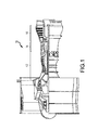
Figure 1 illustrates, in accordance with various embodiments, a side view of a gas turbine engine; -
Figure 2 illustrates, in accordance with various embodiments, a partial cross-sectional view of a compressor portion of a gas turbine engine; and -
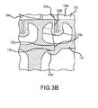
Figures 3A-3D illustrate, in accordance with various embodiments, partial cross-sectional views of a compressor portion of a gas turbine engine. - The detailed description of embodiments herein makes reference to the accompanying drawings, which show embodiments by way of illustration. While these embodiments are described in sufficient detail to enable those skilled in the art to practice the inventions, it should be understood that other embodiments may be realized and that logical and mechanical changes may be made without departing from the scope of the inventions. Thus, the detailed description herein is presented for purposes of illustration only and not for limitation. For example, any reference to singular includes plural embodiments, and any reference to more than one component or step may include a singular embodiment or step. Also, any reference to attached, fixed, connected or the like may include permanent, removable, temporary, partial, full and/or any other possible attachment option.
- As used herein, the term "complementary" means conforming to and/or opposite of an element or feature. For example, an second element that is complementary to a first element would comprise a configuration and/or shape that may conform with the first element, such as by having the opposite shape or configuration.
- As used herein, "aft" refers to the direction associated with the tail of an aircraft, or generally, to the direction of exhaust of the gas turbine. As used herein, "fore" refers to the direction associated with the nose of an aircraft, or generally, to the direction of flight or motion.
- Rotor assemblies in accordance with the present disclosure may comprise rotor segments coupled together without the use of bolts or screws. Specifically, rotor segments may be coupled to one another via a transient liquid phase bonding process. In such configurations, the rotor segments form a rotor assembly which acts as a drum having a nearly-contiguous outer rim and inner rim.
- Accordingly, with reference to
Figure 1 , agas turbine engine 10 is shown. In general terms, gas turbine engine may comprise acompressor section 12. Air may flow throughcompressor section 12 and into acombustion chamber 14, where it is mixed with a fuel source and ignited to produce hot combustion gasses. These hot combustion gasses may drive a series of turbine blades within aturbine section 16, which in turn drive, for example, one or more compressor section blades mechanically coupled thereto. - With reference to
Figures 2 , and3A-3D ,compressor section 12 may comprise ahigh pressure section 100.High pressure section 100 may comprise, for example, arotor assembly 102. In various embodiments,rotor assembly 102 comprises a plurality of rotor segments, such asrotor segments 104a-104d, coupled to one another in the axial direction. For example, one or more ofrotor segments 104a-104d may comprise a plurality of rotor blades. As will be discussed in greater detail,rotor segments 104a-104d may be coupled to one another via a transient liquid phase bonding process. - In various embodiments, rotor segments of
rotor assembly 102 may comprise complementary engagement features which align and engage the rotor segment to adjacent rotor segments. For example,rotor segments 104a-104d may comprise anouter rim 110 and aninner rim 112. In various embodiments,outer rim 110 may comprise engagement features which allowrotor segments 104a-104d to align and couple with each other. In further embodiments,inner rim 112 may comprise engagement features. In yet other embodiments, bothouter rim 110 andinner rim 112 comprise engagement features. Any combination of features disposed alongouter rim 110 and/orinner rim 112 which allowrotor segments 104a-104d to engage and couple with each other is within the scope of the present disclosure. - For example, a particular rotor, such as
rotor segment 104c, may comprise afore engagement feature 114c. For example,fore engagement feature 114c may comprise a shelf disposed at the fore end ofrotor segment 104c.Fore engagement feature 114c may be disposed oninner rim 112 orouter rim 110. -
Rotor segment 104c may further comprise anaft engagement feature 116c. For example,aft engagement feature 116c may comprise a notch disposed at the aft end ofrotor segment 104c. In various embodiments,aft engagement feature 116c is shaped and configured such that it is complementary to a fore engagement feature 114 (of another rotor segment) which allowsaft engagement feature 116c to engage with and couple to fore engagement feature 114 of an adjacent rotor segment. For example,aft engagement feature 116c may be complementary to and configured to engage withfore engagement feature 114d ofrotor segment 104d. Further,rotor segment 104c may comprisefore engagement feature 114c that is complementary to anaft engagement feature 116b ofrotor segment 104b. Although described with regard to specific embodiments, any complementary features such as fore engagement features 114 and aft engagement features 116 which allow adjacent rotor segments to align and engage are within the scope of the present disclosure. For example,rotor segments 104a-104d may comprise fore engagement features 114b-114d and aft engagement features 116a-116c that are reversed from or otherwise differently configured than the embodiments previously described. - In various embodiments,
rotor assembly 102 comprises a fore rotor segment, such asrotor segment 104a and a plurality of rotor segments such asrotor segments 104b-104d.Fore rotor segment 104a may comprise anaft engagement feature 116a configured to engage withfore engagement feature 114b ofrotor segment 104b. In various embodiments,fore rotor segment 104a differs fromrotor segments 104b-104d in thatfore rotor segment 104a does not comprise a fore engagement feature, such as 114b-114d. -
Rotor assembly 102 may further comprise arear hub 106. In various embodiments,rear hub 106 is located aft of the aft most rotor segment, such asrotor segment 104d.Rear hub 106 may comprise a fore engagement feature configured to engage with an aft engagement feature of aftmost rotor segment 104d. - In various embodiments, rotor segments such as
rotor segment 104b may comprise one or more fore sealing surfaces 120b and one or more aft sealingsurfaces 122b. For example, rotor segmentfore sealing surfaces 120b may be surfaces that are complementary to aft sealing surfaces of another segment, such as aft sealing surfaces ofrotor segment 104a. Further, aft sealingsurfaces 122b may be surfaces that are complementary to fore sealing surfaces 120c ofrotor segment 104c. In various embodiments, sealing surfaces such as 120a-120c and 122a-122c may be configured to be aligned and held in contact with complementary sealing surfaces, allowing both surfaces to form an air-tight seal. -
Rotor segments 104a-104d andrear hub 106 may, for example be fused together via a transient liquid phase bonding process. A transient liquid phase bonding process allowsrotor segments 104a-104d to be fused together without using a traditional welding process. Benefits of using a transient liquid phase bonding process may include less cost and effort to clean surfaces after welding, reducing the accumulation of welding material within the rotors segments (also known as backsplash), and reducing the potential for stress, deformation, or other undesirable effect that may be introduced into the rotor segments by the heat of welding. - In various embodiments, rotor segments, such as
rotor segment fore engagement feature 114c andaft engagement feature 116b and aligningfore sealing surface 120c and aft sealingsurface 122b. Once aligned, a suitable bonding liquid may be applied to one or more surfaces, components, or features ofrotor segment 104b and/or 104c to fuse the two rotor segments. In various embodiments, a suitable bonding liquid may be applied tofore sealing surface 120b and/or aft sealingsurface 120c. In further embodiments, a suitable liquid may be applied tofore engagement feature 114c andaft engagement feature 116b. Once a suitable liquid has been applied to the desired surface and/or feature (e.g., surfaces 120c and 122b, engagement features 114c and 116b), sealingsurfaces rotor segments segments 104a-104d andrear hub 106. - In various embodiments, suitable liquids for the transient liquid phase bonding of
rotor segments 104a-104d andrear hub 106 may comprise, for example, tin, copper, nickel, or indium. Suitable transient liquid phase bonding liquids may, for example, facilitate interdiffusion between two surfaces such that the material of the surfaces (the "parent material") is in a non-eutectic state. This allows the bonding of the surfaces to near the melting point of the parent material, instead of at a lower melting point (as is the case with other techniques, such as conventional brazing processes). As such, liquids having suitable melting point temperature and solubility and diffusivity in the material of the rotor segments, and is capable of fusingrotor segments 104a-104d andrear hub 106, are within the scope of the present disclosure. Although the figures and description show only four rotor segments, it would be understood by those of ordinary skill in the art that the features and bonding described herein may be applied to engines with fewer or more rotor segments. - Benefits, other advantages, and solutions to problems have been described herein with regard to specific embodiments. Furthermore, the connecting lines shown in the various figures contained herein are intended to represent exemplary functional relationships and/or physical couplings between the various elements. It should be noted that many alternative or additional functional relationships or physical connections may be present in a practical system. However, the benefits, advantages, solutions to problems, and any elements that may cause any benefit, advantage, or solution to occur or become more pronounced are not to be construed as critical, required, or essential features or elements of the inventions. The scope of the inventions is accordingly to be limited by nothing other than the appended claims, in which reference to an element in the singular is not intended to mean "one and only one" unless explicitly so stated, but rather "one or more." Moreover, where a phrase similar to "at least one of A, B, or C" is used in the claims, it is intended that the phrase be interpreted to mean that A alone may be present in an embodiment, B alone may be present in an embodiment, C alone may be present in an embodiment, or that any combination of the elements A, B and C may be present in a single embodiment; for example, A and B, A and C, B and C, or A and B and C. Different cross-hatching is used throughout the figures to denote different parts but not necessarily to denote the same or different materials.
- Systems, methods and apparatus are provided herein. In the detailed description herein, references to "one embodiment," "an embodiment," "an example embodiment," etc., indicate that the embodiment described may include a particular feature, structure, or characteristic, but every embodiment may not necessarily include the particular feature, structure, or characteristic. Moreover, such phrases are not necessarily referring to the same embodiment. Further, when a particular feature, structure, or characteristic is described in connection with an embodiment, it is submitted that it is within the knowledge of one skilled in the art to affect such feature, structure, or characteristic in connection with other embodiments whether or not explicitly described. After reading the description, it will be apparent to one skilled in the relevant art(s) how to implement the disclosure in alternative embodiments.
- Furthermore, no element, component, or method step in the present disclosure is intended to be dedicated to the public regardless of whether the element, component, or method step is explicitly recited in the claims. No claim element herein is to be construed under the provisions of 35 U.S.C. 112(f), unless the element is expressly recited using the phrase "means for." As used herein, the terms "comprises," "comprising," or any other variation thereof, are intended to cover a non-exclusive inclusion, such that a process, method, article, or apparatus that comprises a list of elements does not include only those elements but may include other elements not expressly listed or inherent to such process, method, article, or apparatus.
Claims (15)
- A gas turbine engine compressor comprising:a first rotor segment (104b) comprising a first inner rim (112) and a first aft sealing surface (122b), wherein the first inner rim (112) comprises a first aft engagement feature (116b); anda second rotor segment (104c) positioned aft of the first rotor segment (104b) and comprising a second inner rim (112) and a second fore sealing surface (120c),
wherein the second inner rim (112) comprises a second fore engagement feature (114c),
wherein the first aft sealing surface (122b) and the second fore sealing surface (120c) are complementary to each other and are configured to be bonded together via a transient liquid phase diffusion process. - The gas turbine engine compressor of claim 1, further comprising a rear hub (106) which includes a hub engagement feature disposed on a fore end of the rear hub (106), the hub engagement feature complementary to a second aft engagement feature (116c) disposed on an aft end of the second rotor segment (104c).
- The gas turbine engine compressor of claim 1 or 2, wherein a first fore sealing surface (120b) and a second aft sealing surface (122c) are bonded together.
- The gas turbine engine compressor of claim 1, 2 or 3, wherein the transient liquid phase diffusion process comprises applying a transient liquid to at least one of the first aft sealing surface (122b) or the second fore sealing surface (120c) and contacting the first aft sealing surface (122b) and the second fore sealing surface (120c) to fuse the first aft sealing surface (122b) and the second fore sealing surface (120c) together.
- A gas turbine engine (10) comprising:an axial compressor comprising a rotary assembly, wherein the rotary assembly comprises a first rotor segment (104b) comprising a first inner rim (112) and a first aft sealing surface (122b), wherein the first inner rim (112) comprises a first aft engagement feature (116b); anda second rotor segment (104c) positioned aft of the first rotor segment (104b) and comprising a second inner rim (112) and a second fore sealing surface (120c),
wherein the second inner rim (112) comprises a second fore engagement feature (114c) that is complementary to the first aft engagement feature (116b),
wherein the first aft sealing surface (122b) and the second fore sealing surface (120c) are complementary to each other and bonded together via a transient liquid phase diffusion process. - The gas turbine engine of claim 5, further comprising a rear hub (106) having a hub engagement feature disposed on a fore end of the rear hub (106), the hub engagement feature being complementary to a second aft engagement feature (116c) disposed on an aft end of the second rotor segment (104b).
- The gas turbine engine of claim 5 or 6, wherein the second rotor segment (104c) comprises a plurality of blades.
- The gas turbine engine of claim 5, 6 or 7, wherein the transient liquid phase diffusion process comprises applying a transient liquid to one of the first aft sealing surface (122b) and the second fore sealing surface (120c) and contacting the first aft sealing surface (122b) and the second fore sealing surface (120c) to fuse the first aft sealing surface (122b) and the second fore sealing surface (120c) together.
- The gas turbine engine compressor or gas turbine engine of any preceding claim, wherein the first aft sealing surface (122b) is disposed in a first outer rim (110) and the second fore sealing surface (120c) is disposed in a second outer rim (110).
- The gas turbine engine compressor or gas turbine engine of any preceding claim, wherein the second fore engagement feature (114c) comprises a shelf.
- The gas turbine engine compressor or gas turbine engine of claim 10, wherein the first aft engagement feature (116b) comprises a notch.
- The gas turbine engine compressor or gas turbine engine of any preceding claim, wherein the first rotor segment (104b) is a fore rotor segment.
- The gas turbine engine compressor or gas turbine engine of any preceding claim, further comprising a third rotor assembly (104d) positioned between the first rotor segment (104b) and the second rotor segment (104c) and comprising a third aft engagement feature (116d) and a third fore engagement feature (114d).
- The gas turbine engine compressor of claim 13, wherein the third aft engagement (116d) feature is complementary to the second fore engagement feature (114c) of the second rotor segment (104c) and the third fore engagement feature (114d) is complementary to the first aft engagement feature (116d) of the first rotor segment (104b).
- The gas turbine engine of claim 13, wherein the third fore engagement feature (102d) is complementary to the first aft engagement feature (116b) of the first rotor segment (104b) and the third aft engagement feature (116d) is complementary to the second fore engagement feature (114c) of the second rotor segment (104c).
Applications Claiming Priority (1)
| Application Number | Priority Date | Filing Date | Title |
|---|---|---|---|
| US201462031669P | 2014-07-31 | 2014-07-31 |
Publications (2)
| Publication Number | Publication Date |
|---|---|
| EP2980362A1 true EP2980362A1 (en) | 2016-02-03 |
| EP2980362B1 EP2980362B1 (en) | 2017-04-12 |
Family
ID=53776387
Family Applications (1)
| Application Number | Title | Priority Date | Filing Date |
|---|---|---|---|
| EP15178808.0A Active EP2980362B1 (en) | 2014-07-31 | 2015-07-29 | Gas turbine engine axial drum-style compressor rotor assembly |
Country Status (2)
| Country | Link |
|---|---|
| US (1) | US9897098B2 (en) |
| EP (1) | EP2980362B1 (en) |
Families Citing this family (1)
| Publication number | Priority date | Publication date | Assignee | Title |
|---|---|---|---|---|
| US10145245B2 (en) * | 2013-09-24 | 2018-12-04 | United Technologies Corporation | Bonded multi-piece gas turbine engine component |
Citations (3)
| Publication number | Priority date | Publication date | Assignee | Title |
|---|---|---|---|---|
| EP2236757A2 (en) * | 2009-03-17 | 2010-10-06 | United Technologies Corporation | Split rotor disk assembly for a gas turbine engine |
| US20120292860A1 (en) * | 2011-05-20 | 2012-11-22 | Frank Moehrle | Turbine combustion system transition seals |
| EP2586968A2 (en) * | 2011-10-28 | 2013-05-01 | United Technologies Corporation | Secondary flow arrangement for slotted rotor |
Family Cites Families (5)
| Publication number | Priority date | Publication date | Assignee | Title |
|---|---|---|---|---|
| US7559745B2 (en) * | 2006-03-21 | 2009-07-14 | United Technologies Corporation | Tip clearance centrifugal compressor impeller |
| US9938831B2 (en) * | 2011-10-28 | 2018-04-10 | United Technologies Corporation | Spoked rotor for a gas turbine engine |
| US8944762B2 (en) * | 2011-10-28 | 2015-02-03 | United Technologies Corporation | Spoked spacer for a gas turbine engine |
| US8961132B2 (en) * | 2011-10-28 | 2015-02-24 | United Technologies Corporation | Secondary flow arrangement for slotted rotor |
| US8784062B2 (en) * | 2011-10-28 | 2014-07-22 | United Technologies Corporation | Asymmetrically slotted rotor for a gas turbine engine |
-
2015
- 2015-07-07 US US14/793,503 patent/US9897098B2/en active Active
- 2015-07-29 EP EP15178808.0A patent/EP2980362B1/en active Active
Patent Citations (3)
| Publication number | Priority date | Publication date | Assignee | Title |
|---|---|---|---|---|
| EP2236757A2 (en) * | 2009-03-17 | 2010-10-06 | United Technologies Corporation | Split rotor disk assembly for a gas turbine engine |
| US20120292860A1 (en) * | 2011-05-20 | 2012-11-22 | Frank Moehrle | Turbine combustion system transition seals |
| EP2586968A2 (en) * | 2011-10-28 | 2013-05-01 | United Technologies Corporation | Secondary flow arrangement for slotted rotor |
Also Published As
| Publication number | Publication date |
|---|---|
| US9897098B2 (en) | 2018-02-20 |
| US20160032937A1 (en) | 2016-02-04 |
| EP2980362B1 (en) | 2017-04-12 |
Similar Documents
| Publication | Publication Date | Title |
|---|---|---|
| US9970317B2 (en) | Vane assembly for a gas turbine engine | |
| US11015471B2 (en) | Clamping seal for jet engine mid-turbine frame | |
| CN108868902B (en) | Component with co-bonded composite material and metal ring and method of assembling the same | |
| US9803489B2 (en) | Low loss baffled serpentine turns | |
| US20160186614A1 (en) | Turbine exhaust case assembly | |
| EP3489463B1 (en) | Composite fan platform lug reinforcement | |
| EP3051072B1 (en) | Airfoil module | |
| JP5681728B2 (en) | Integrated aircraft engine flow path structure | |
| EP3026217B1 (en) | Turbine rotor or stator segmented sideplates with anti-rotation | |
| EP3091200B1 (en) | Turbine case coupling | |
| EP2980362B1 (en) | Gas turbine engine axial drum-style compressor rotor assembly | |
| US10082203B2 (en) | Low-cost epicyclic gear carrier and method of making the same | |
| EP2938884B1 (en) | Interconnection of rotating components of a compressor of a gas turbine | |
| EP2938825B1 (en) | Turbomachine with clamp coupling shaft and rotor hub together | |
| US9926789B2 (en) | Flow splitting baffle | |
| EP2933437A1 (en) | Systems and methods for anti-rotation features | |
| EP3252294B1 (en) | Toroidal spinner aft flange | |
| CN107882597A (en) | Duplex pull rod component and its assemble method for gas-turbine unit | |
| US10815830B2 (en) | Lightweight tierod | |
| EP2930304B1 (en) | High pressure compressor thermal shield apparatus and system |
Legal Events
| Date | Code | Title | Description |
|---|---|---|---|
| PUAI | Public reference made under article 153(3) epc to a published international application that has entered the european phase |
Free format text: ORIGINAL CODE: 0009012 |
|
| AK | Designated contracting states |
Kind code of ref document: A1 Designated state(s): AL AT BE BG CH CY CZ DE DK EE ES FI FR GB GR HR HU IE IS IT LI LT LU LV MC MK MT NL NO PL PT RO RS SE SI SK SM TR |
|
| AX | Request for extension of the european patent |
Extension state: BA ME |
|
| 17P | Request for examination filed |
Effective date: 20160803 |
|
| RBV | Designated contracting states (corrected) |
Designated state(s): AL AT BE BG CH CY CZ DE DK EE ES FI FR GB GR HR HU IE IS IT LI LT LU LV MC MK MT NL NO PL PT RO RS SE SI SK SM TR |
|
| RAP1 | Party data changed (applicant data changed or rights of an application transferred) |
Owner name: UNITED TECHNOLOGIES CORPORATION |
|
| REG | Reference to a national code |
Ref country code: DE Ref legal event code: R079 Ref document number: 602015002214 Country of ref document: DE Free format text: PREVIOUS MAIN CLASS: F01D0011000000 Ipc: F04D0017080000 |
|
| RIC1 | Information provided on ipc code assigned before grant |
Ipc: F01D 11/00 20060101AFI20160930BHEP |
|
| GRAP | Despatch of communication of intention to grant a patent |
Free format text: ORIGINAL CODE: EPIDOSNIGR1 |
|
| RIC1 | Information provided on ipc code assigned before grant |
Ipc: F04D 29/08 20060101ALI20161104BHEP Ipc: F04D 17/08 20060101AFI20161104BHEP Ipc: F04D 29/28 20060101ALI20161104BHEP Ipc: F01D 11/00 20060101ALI20161104BHEP |
|
| INTG | Intention to grant announced |
Effective date: 20161130 |
|
| GRAS | Grant fee paid |
Free format text: ORIGINAL CODE: EPIDOSNIGR3 |
|
| GRAA | (expected) grant |
Free format text: ORIGINAL CODE: 0009210 |
|
| AK | Designated contracting states |
Kind code of ref document: B1 Designated state(s): AL AT BE BG CH CY CZ DE DK EE ES FI FR GB GR HR HU IE IS IT LI LT LU LV MC MK MT NL NO PL PT RO RS SE SI SK SM TR |
|
| REG | Reference to a national code |
Ref country code: GB Ref legal event code: FG4D |
|
| REG | Reference to a national code |
Ref country code: CH Ref legal event code: EP |
|
| REG | Reference to a national code |
Ref country code: IE Ref legal event code: FG4D |
|
| REG | Reference to a national code |
Ref country code: AT Ref legal event code: REF Ref document number: 884198 Country of ref document: AT Kind code of ref document: T Effective date: 20170515 |
|
| REG | Reference to a national code |
Ref country code: DE Ref legal event code: R096 Ref document number: 602015002214 Country of ref document: DE |
|
| REG | Reference to a national code |
Ref country code: FR Ref legal event code: PLFP Year of fee payment: 3 |
|
| REG | Reference to a national code |
Ref country code: DE Ref legal event code: R082 Ref document number: 602015002214 Country of ref document: DE Representative=s name: SCHMITT-NILSON SCHRAUD WAIBEL WOHLFROM PATENTA, DE |
|
| REG | Reference to a national code |
Ref country code: NL Ref legal event code: MP Effective date: 20170412 |
|
| REG | Reference to a national code |
Ref country code: LT Ref legal event code: MG4D |
|
| REG | Reference to a national code |
Ref country code: AT Ref legal event code: MK05 Ref document number: 884198 Country of ref document: AT Kind code of ref document: T Effective date: 20170412 |
|
| PG25 | Lapsed in a contracting state [announced via postgrant information from national office to epo] |
Ref country code: NL Free format text: LAPSE BECAUSE OF FAILURE TO SUBMIT A TRANSLATION OF THE DESCRIPTION OR TO PAY THE FEE WITHIN THE PRESCRIBED TIME-LIMIT Effective date: 20170412 |
|
| PG25 | Lapsed in a contracting state [announced via postgrant information from national office to epo] |
Ref country code: NO Free format text: LAPSE BECAUSE OF FAILURE TO SUBMIT A TRANSLATION OF THE DESCRIPTION OR TO PAY THE FEE WITHIN THE PRESCRIBED TIME-LIMIT Effective date: 20170712 Ref country code: ES Free format text: LAPSE BECAUSE OF FAILURE TO SUBMIT A TRANSLATION OF THE DESCRIPTION OR TO PAY THE FEE WITHIN THE PRESCRIBED TIME-LIMIT Effective date: 20170412 Ref country code: GR Free format text: LAPSE BECAUSE OF FAILURE TO SUBMIT A TRANSLATION OF THE DESCRIPTION OR TO PAY THE FEE WITHIN THE PRESCRIBED TIME-LIMIT Effective date: 20170713 Ref country code: HR Free format text: LAPSE BECAUSE OF FAILURE TO SUBMIT A TRANSLATION OF THE DESCRIPTION OR TO PAY THE FEE WITHIN THE PRESCRIBED TIME-LIMIT Effective date: 20170412 Ref country code: FI Free format text: LAPSE BECAUSE OF FAILURE TO SUBMIT A TRANSLATION OF THE DESCRIPTION OR TO PAY THE FEE WITHIN THE PRESCRIBED TIME-LIMIT Effective date: 20170412 Ref country code: LT Free format text: LAPSE BECAUSE OF FAILURE TO SUBMIT A TRANSLATION OF THE DESCRIPTION OR TO PAY THE FEE WITHIN THE PRESCRIBED TIME-LIMIT Effective date: 20170412 Ref country code: AT Free format text: LAPSE BECAUSE OF FAILURE TO SUBMIT A TRANSLATION OF THE DESCRIPTION OR TO PAY THE FEE WITHIN THE PRESCRIBED TIME-LIMIT Effective date: 20170412 |
|
| PG25 | Lapsed in a contracting state [announced via postgrant information from national office to epo] |
Ref country code: RS Free format text: LAPSE BECAUSE OF FAILURE TO SUBMIT A TRANSLATION OF THE DESCRIPTION OR TO PAY THE FEE WITHIN THE PRESCRIBED TIME-LIMIT Effective date: 20170412 Ref country code: LV Free format text: LAPSE BECAUSE OF FAILURE TO SUBMIT A TRANSLATION OF THE DESCRIPTION OR TO PAY THE FEE WITHIN THE PRESCRIBED TIME-LIMIT Effective date: 20170412 Ref country code: BG Free format text: LAPSE BECAUSE OF FAILURE TO SUBMIT A TRANSLATION OF THE DESCRIPTION OR TO PAY THE FEE WITHIN THE PRESCRIBED TIME-LIMIT Effective date: 20170712 Ref country code: SE Free format text: LAPSE BECAUSE OF FAILURE TO SUBMIT A TRANSLATION OF THE DESCRIPTION OR TO PAY THE FEE WITHIN THE PRESCRIBED TIME-LIMIT Effective date: 20170412 Ref country code: PL Free format text: LAPSE BECAUSE OF FAILURE TO SUBMIT A TRANSLATION OF THE DESCRIPTION OR TO PAY THE FEE WITHIN THE PRESCRIBED TIME-LIMIT Effective date: 20170412 Ref country code: IS Free format text: LAPSE BECAUSE OF FAILURE TO SUBMIT A TRANSLATION OF THE DESCRIPTION OR TO PAY THE FEE WITHIN THE PRESCRIBED TIME-LIMIT Effective date: 20170812 |
|
| REG | Reference to a national code |
Ref country code: DE Ref legal event code: R097 Ref document number: 602015002214 Country of ref document: DE |
|
| PG25 | Lapsed in a contracting state [announced via postgrant information from national office to epo] |
Ref country code: SK Free format text: LAPSE BECAUSE OF FAILURE TO SUBMIT A TRANSLATION OF THE DESCRIPTION OR TO PAY THE FEE WITHIN THE PRESCRIBED TIME-LIMIT Effective date: 20170412 Ref country code: DK Free format text: LAPSE BECAUSE OF FAILURE TO SUBMIT A TRANSLATION OF THE DESCRIPTION OR TO PAY THE FEE WITHIN THE PRESCRIBED TIME-LIMIT Effective date: 20170412 Ref country code: CZ Free format text: LAPSE BECAUSE OF FAILURE TO SUBMIT A TRANSLATION OF THE DESCRIPTION OR TO PAY THE FEE WITHIN THE PRESCRIBED TIME-LIMIT Effective date: 20170412 Ref country code: EE Free format text: LAPSE BECAUSE OF FAILURE TO SUBMIT A TRANSLATION OF THE DESCRIPTION OR TO PAY THE FEE WITHIN THE PRESCRIBED TIME-LIMIT Effective date: 20170412 Ref country code: RO Free format text: LAPSE BECAUSE OF FAILURE TO SUBMIT A TRANSLATION OF THE DESCRIPTION OR TO PAY THE FEE WITHIN THE PRESCRIBED TIME-LIMIT Effective date: 20170412 |
|
| PLBE | No opposition filed within time limit |
Free format text: ORIGINAL CODE: 0009261 |
|
| STAA | Information on the status of an ep patent application or granted ep patent |
Free format text: STATUS: NO OPPOSITION FILED WITHIN TIME LIMIT |
|
| PG25 | Lapsed in a contracting state [announced via postgrant information from national office to epo] |
Ref country code: SM Free format text: LAPSE BECAUSE OF FAILURE TO SUBMIT A TRANSLATION OF THE DESCRIPTION OR TO PAY THE FEE WITHIN THE PRESCRIBED TIME-LIMIT Effective date: 20170412 Ref country code: IT Free format text: LAPSE BECAUSE OF FAILURE TO SUBMIT A TRANSLATION OF THE DESCRIPTION OR TO PAY THE FEE WITHIN THE PRESCRIBED TIME-LIMIT Effective date: 20170412 |
|
| 26N | No opposition filed |
Effective date: 20180115 |
|
| REG | Reference to a national code |
Ref country code: IE Ref legal event code: MM4A |
|
| REG | Reference to a national code |
Ref country code: BE Ref legal event code: MM Effective date: 20170731 |
|
| PG25 | Lapsed in a contracting state [announced via postgrant information from national office to epo] |
Ref country code: SI Free format text: LAPSE BECAUSE OF FAILURE TO SUBMIT A TRANSLATION OF THE DESCRIPTION OR TO PAY THE FEE WITHIN THE PRESCRIBED TIME-LIMIT Effective date: 20170412 |
|
| REG | Reference to a national code |
Ref country code: FR Ref legal event code: PLFP Year of fee payment: 4 |
|
| PG25 | Lapsed in a contracting state [announced via postgrant information from national office to epo] |
Ref country code: LU Free format text: LAPSE BECAUSE OF NON-PAYMENT OF DUE FEES Effective date: 20170729 |
|
| PG25 | Lapsed in a contracting state [announced via postgrant information from national office to epo] |
Ref country code: IE Free format text: LAPSE BECAUSE OF NON-PAYMENT OF DUE FEES Effective date: 20170729 |
|
| PG25 | Lapsed in a contracting state [announced via postgrant information from national office to epo] |
Ref country code: BE Free format text: LAPSE BECAUSE OF NON-PAYMENT OF DUE FEES Effective date: 20170731 |
|
| PG25 | Lapsed in a contracting state [announced via postgrant information from national office to epo] |
Ref country code: MT Free format text: LAPSE BECAUSE OF NON-PAYMENT OF DUE FEES Effective date: 20170729 |
|
| REG | Reference to a national code |
Ref country code: CH Ref legal event code: PL |
|
| PG25 | Lapsed in a contracting state [announced via postgrant information from national office to epo] |
Ref country code: CH Free format text: LAPSE BECAUSE OF NON-PAYMENT OF DUE FEES Effective date: 20180731 Ref country code: LI Free format text: LAPSE BECAUSE OF NON-PAYMENT OF DUE FEES Effective date: 20180731 |
|
| PG25 | Lapsed in a contracting state [announced via postgrant information from national office to epo] |
Ref country code: HU Free format text: LAPSE BECAUSE OF FAILURE TO SUBMIT A TRANSLATION OF THE DESCRIPTION OR TO PAY THE FEE WITHIN THE PRESCRIBED TIME-LIMIT; INVALID AB INITIO Effective date: 20150729 Ref country code: MC Free format text: LAPSE BECAUSE OF FAILURE TO SUBMIT A TRANSLATION OF THE DESCRIPTION OR TO PAY THE FEE WITHIN THE PRESCRIBED TIME-LIMIT Effective date: 20170412 |
|
| PG25 | Lapsed in a contracting state [announced via postgrant information from national office to epo] |
Ref country code: CY Free format text: LAPSE BECAUSE OF FAILURE TO SUBMIT A TRANSLATION OF THE DESCRIPTION OR TO PAY THE FEE WITHIN THE PRESCRIBED TIME-LIMIT Effective date: 20170412 |
|
| PG25 | Lapsed in a contracting state [announced via postgrant information from national office to epo] |
Ref country code: MK Free format text: LAPSE BECAUSE OF FAILURE TO SUBMIT A TRANSLATION OF THE DESCRIPTION OR TO PAY THE FEE WITHIN THE PRESCRIBED TIME-LIMIT Effective date: 20170412 |
|
| PG25 | Lapsed in a contracting state [announced via postgrant information from national office to epo] |
Ref country code: TR Free format text: LAPSE BECAUSE OF FAILURE TO SUBMIT A TRANSLATION OF THE DESCRIPTION OR TO PAY THE FEE WITHIN THE PRESCRIBED TIME-LIMIT Effective date: 20170412 |
|
| PG25 | Lapsed in a contracting state [announced via postgrant information from national office to epo] |
Ref country code: PT Free format text: LAPSE BECAUSE OF FAILURE TO SUBMIT A TRANSLATION OF THE DESCRIPTION OR TO PAY THE FEE WITHIN THE PRESCRIBED TIME-LIMIT Effective date: 20170412 |
|
| PG25 | Lapsed in a contracting state [announced via postgrant information from national office to epo] |
Ref country code: AL Free format text: LAPSE BECAUSE OF FAILURE TO SUBMIT A TRANSLATION OF THE DESCRIPTION OR TO PAY THE FEE WITHIN THE PRESCRIBED TIME-LIMIT Effective date: 20170412 |
|
| REG | Reference to a national code |
Ref country code: DE Ref legal event code: R081 Ref document number: 602015002214 Country of ref document: DE Owner name: RAYTHEON TECHNOLOGIES CORPORATION (N.D.GES.D.S, US Free format text: FORMER OWNER: UNITED TECHNOLOGIES CORPORATION, FARMINGTON, CONN., US Ref country code: DE Ref legal event code: R081 Ref document number: 602015002214 Country of ref document: DE Owner name: RTX CORPORATION (N.D.GES.D. STAATES DELAWARE),, US Free format text: FORMER OWNER: UNITED TECHNOLOGIES CORPORATION, FARMINGTON, CONN., US |
|
| P01 | Opt-out of the competence of the unified patent court (upc) registered |
Effective date: 20230520 |
|
| PGFP | Annual fee paid to national office [announced via postgrant information from national office to epo] |
Ref country code: GB Payment date: 20250619 Year of fee payment: 11 |
|
| PGFP | Annual fee paid to national office [announced via postgrant information from national office to epo] |
Ref country code: FR Payment date: 20250620 Year of fee payment: 11 |
|
| PGFP | Annual fee paid to national office [announced via postgrant information from national office to epo] |
Ref country code: DE Payment date: 20250620 Year of fee payment: 11 |
|
| REG | Reference to a national code |
Ref country code: DE Ref legal event code: R081 Ref document number: 602015002214 Country of ref document: DE Owner name: RTX CORPORATION (N.D.GES.D. STAATES DELAWARE),, US Free format text: FORMER OWNER: RAYTHEON TECHNOLOGIES CORPORATION (N.D.GES.D.STAATES DELAWARE), ARLINGTON, VA, US |