EP2980358A1 - Gas turbine engine with axial compressor having improved air sealing - Google Patents
Gas turbine engine with axial compressor having improved air sealing Download PDFInfo
- Publication number
- EP2980358A1 EP2980358A1 EP15178880.9A EP15178880A EP2980358A1 EP 2980358 A1 EP2980358 A1 EP 2980358A1 EP 15178880 A EP15178880 A EP 15178880A EP 2980358 A1 EP2980358 A1 EP 2980358A1
- Authority
- EP
- European Patent Office
- Prior art keywords
- gas turbine
- turbine engine
- axial
- compressor
- outer rim
- Prior art date
- Legal status (The legal status is an assumption and is not a legal conclusion. Google has not performed a legal analysis and makes no representation as to the accuracy of the status listed.)
- Granted
Links
Images


Classifications
-
- F—MECHANICAL ENGINEERING; LIGHTING; HEATING; WEAPONS; BLASTING
- F01—MACHINES OR ENGINES IN GENERAL; ENGINE PLANTS IN GENERAL; STEAM ENGINES
- F01D—NON-POSITIVE DISPLACEMENT MACHINES OR ENGINES, e.g. STEAM TURBINES
- F01D11/00—Preventing or minimising internal leakage of working-fluid, e.g. between stages
- F01D11/02—Preventing or minimising internal leakage of working-fluid, e.g. between stages by non-contact sealings, e.g. of labyrinth type
- F01D11/04—Preventing or minimising internal leakage of working-fluid, e.g. between stages by non-contact sealings, e.g. of labyrinth type using sealing fluid, e.g. steam
-
- F—MECHANICAL ENGINEERING; LIGHTING; HEATING; WEAPONS; BLASTING
- F01—MACHINES OR ENGINES IN GENERAL; ENGINE PLANTS IN GENERAL; STEAM ENGINES
- F01D—NON-POSITIVE DISPLACEMENT MACHINES OR ENGINES, e.g. STEAM TURBINES
- F01D5/00—Blades; Blade-carrying members; Heating, heat-insulating, cooling or antivibration means on the blades or the members
- F01D5/02—Blade-carrying members, e.g. rotors
- F01D5/06—Rotors for more than one axial stage, e.g. of drum or multiple disc type; Details thereof, e.g. shafts, shaft connections
-
- F—MECHANICAL ENGINEERING; LIGHTING; HEATING; WEAPONS; BLASTING
- F01—MACHINES OR ENGINES IN GENERAL; ENGINE PLANTS IN GENERAL; STEAM ENGINES
- F01D—NON-POSITIVE DISPLACEMENT MACHINES OR ENGINES, e.g. STEAM TURBINES
- F01D11/00—Preventing or minimising internal leakage of working-fluid, e.g. between stages
- F01D11/001—Preventing or minimising internal leakage of working-fluid, e.g. between stages for sealing space between stator blade and rotor
-
- F—MECHANICAL ENGINEERING; LIGHTING; HEATING; WEAPONS; BLASTING
- F01—MACHINES OR ENGINES IN GENERAL; ENGINE PLANTS IN GENERAL; STEAM ENGINES
- F01D—NON-POSITIVE DISPLACEMENT MACHINES OR ENGINES, e.g. STEAM TURBINES
- F01D11/00—Preventing or minimising internal leakage of working-fluid, e.g. between stages
- F01D11/005—Sealing means between non relatively rotating elements
-
- F—MECHANICAL ENGINEERING; LIGHTING; HEATING; WEAPONS; BLASTING
- F01—MACHINES OR ENGINES IN GENERAL; ENGINE PLANTS IN GENERAL; STEAM ENGINES
- F01D—NON-POSITIVE DISPLACEMENT MACHINES OR ENGINES, e.g. STEAM TURBINES
- F01D11/00—Preventing or minimising internal leakage of working-fluid, e.g. between stages
- F01D11/005—Sealing means between non relatively rotating elements
- F01D11/006—Sealing the gap between rotor blades or blades and rotor
-
- F—MECHANICAL ENGINEERING; LIGHTING; HEATING; WEAPONS; BLASTING
- F01—MACHINES OR ENGINES IN GENERAL; ENGINE PLANTS IN GENERAL; STEAM ENGINES
- F01D—NON-POSITIVE DISPLACEMENT MACHINES OR ENGINES, e.g. STEAM TURBINES
- F01D5/00—Blades; Blade-carrying members; Heating, heat-insulating, cooling or antivibration means on the blades or the members
- F01D5/12—Blades
- F01D5/14—Form or construction
- F01D5/18—Hollow blades, i.e. blades with cooling or heating channels or cavities; Heating, heat-insulating or cooling means on blades
-
- F—MECHANICAL ENGINEERING; LIGHTING; HEATING; WEAPONS; BLASTING
- F01—MACHINES OR ENGINES IN GENERAL; ENGINE PLANTS IN GENERAL; STEAM ENGINES
- F01D—NON-POSITIVE DISPLACEMENT MACHINES OR ENGINES, e.g. STEAM TURBINES
- F01D5/00—Blades; Blade-carrying members; Heating, heat-insulating, cooling or antivibration means on the blades or the members
- F01D5/12—Blades
- F01D5/22—Blade-to-blade connections, e.g. for damping vibrations
- F01D5/225—Blade-to-blade connections, e.g. for damping vibrations by shrouding
-
- F—MECHANICAL ENGINEERING; LIGHTING; HEATING; WEAPONS; BLASTING
- F01—MACHINES OR ENGINES IN GENERAL; ENGINE PLANTS IN GENERAL; STEAM ENGINES
- F01D—NON-POSITIVE DISPLACEMENT MACHINES OR ENGINES, e.g. STEAM TURBINES
- F01D5/00—Blades; Blade-carrying members; Heating, heat-insulating, cooling or antivibration means on the blades or the members
- F01D5/12—Blades
- F01D5/22—Blade-to-blade connections, e.g. for damping vibrations
- F01D5/24—Blade-to-blade connections, e.g. for damping vibrations using wire or the like
-
- F—MECHANICAL ENGINEERING; LIGHTING; HEATING; WEAPONS; BLASTING
- F05—INDEXING SCHEMES RELATING TO ENGINES OR PUMPS IN VARIOUS SUBCLASSES OF CLASSES F01-F04
- F05D—INDEXING SCHEME FOR ASPECTS RELATING TO NON-POSITIVE-DISPLACEMENT MACHINES OR ENGINES, GAS-TURBINES OR JET-PROPULSION PLANTS
- F05D2240/00—Components
- F05D2240/55—Seals
-
- Y—GENERAL TAGGING OF NEW TECHNOLOGICAL DEVELOPMENTS; GENERAL TAGGING OF CROSS-SECTIONAL TECHNOLOGIES SPANNING OVER SEVERAL SECTIONS OF THE IPC; TECHNICAL SUBJECTS COVERED BY FORMER USPC CROSS-REFERENCE ART COLLECTIONS [XRACs] AND DIGESTS
- Y02—TECHNOLOGIES OR APPLICATIONS FOR MITIGATION OR ADAPTATION AGAINST CLIMATE CHANGE
- Y02T—CLIMATE CHANGE MITIGATION TECHNOLOGIES RELATED TO TRANSPORTATION
- Y02T50/00—Aeronautics or air transport
- Y02T50/60—Efficient propulsion technologies, e.g. for aircraft
Definitions
- the present disclosure relates generally to axial compressor portions of gas turbine engines and more specifically, to axial compressors having improved air sealing of slots in the rotor assembly.
- Gas turbine engines generally include a compressor, such as an axial compressor, to pressurize inflowing air.
- Axial compressors may include number of rotor segments adjacent and coupled to each other in the axial direction.
- the outer rim of the rotor segments may utilize expansion slots to help reduce hoop stresses on the outer rim.
- air enters the expansion slots and may mix with and increase the temperature of cooling air within the rotor assembly. Cooling of the inner and outer rim may tend to prevent fatigue and potentially extend the life of the material of the rims. Hot air may escape through, for example, the expansion slots, and thereby reducing the cooling effect of the cooling air and/or interrupting the aerodynamic flow of air through the compressor.
- a gas turbine engine compressor comprises a rotary assembly comprising an outer rim and a blade, an expansion slot cut through an outer surface and an inner surface of the outer rim, wherein the slot has a fore end and an aft end, and a radial seal, and an axial seal disposed at the fore end of the slot.
- the rotary assembly comprises a first rotor segment and a second rotor segment, and the first rotor segment may comprise a spacer and the second rotor segment may comprise a plurality of blades.
- the expansion slot may be disposed in the second rotor segment.
- the axial seal is coupled to the inner surface of the outer rim in the first rotor segment, and may comprise a fin configuration.
- the axial seal may be integral to the inner surface of the outer rim.
- the compressor may comprise a plurality of expansion slots and axial seals, wherein each axial seal corresponds to an expansion slot. Further, expansion slot may be disposed between two of the plurality of blades.
- a gas turbine engine comprises an axial high pressure compressor having a rotary assembly comprising an outer rim and a blade, an expansion slot cut through an outer surface and an inner surface of the outer rim, wherein the slot has a fore end and an aft end, and a radial seal, and an axial seal disposed at the fore end of the slot.
- the rotary assembly comprises a first rotor segment and a second rotor segment, and the first rotor segment may comprise a spacer and the second rotor segment may comprise a plurality of blades.
- the expansion slot may be disposed in the second rotor segment.
- the axial seal is coupled to the inner surface of the outer rim in the first rotor segment, and may comprise a fin configuration.
- the axial seal may be integral to the inner surface of the outer rim.
- the compressor may comprise a plurality of expansion slots and axial seals, wherein each axial seal corresponds to an expansion slot. Further, expansion slot may be disposed between two of the plurality of blades.
- aft refers to the direction associated with the tail of an aircraft, or generally, to the direction of exhaust of the gas turbine.
- forward and/or “fore” refers to the direction associated with the nose of an aircraft, or generally, to the direction of flight or motion.
- Axial compressors in accordance with the present disclosure may include multiple rotor segments having expansion slots in one or more outer surfaces.
- the fore end of the expansion slots may include axial seals configured to reduce or prevent unwanted mixing of hotter air from the expansion slots from entering into cooling air passing through cooling channels of the rotor segments,
- gas turbine engine 10 may comprise a compressor section 12. Air may flow through compressor section 12 and into a combustion chamber 14, where the air is mixed with a fuel source and ignited to produce hot combustion gasses. These hot combustion gasses may drive a series of turbine blades within a turbine section 16, which in turn drive, for example, one or more compressor section blades mechanically coupled thereto.
- compressor section 12 may comprise a high pressure section 100.
- High pressure section 100 may comprise, for example, a plurality of rotor segments adjacent to and coupled to each other in the axial direction.
- high pressure section 100 may comprise a first rotor segment 102.
- first rotor segment 102 may comprise an outer rim 116 having an outer surface 106 and an inner surface 108.
- first rotor segment 102 may comprise a blade segment having a plurality of blades 110. Plurality of blades 110 may be affixed or otherwise coupled to outer surface 106 of first rotor segment 102. In further embodiments, first rotor segment 102 may comprise a spacer segment having zero blades, or a vane segment including nonrotating vanes to direct air to blades in subsequent segments.
- high pressure section 100 may further comprise a second rotor segment 104.
- second rotor segment 104 may comprise a blade segment having a multiplicity of blades 110 affixed or otherwise coupled to outer surface 106 of second rotor segment 104.
- Second rotor segment 104 may be adjacent to and coupled to first rotor segment 102.
- second rotor segment 104 is positioned aft of first rotor segment 102.
- outer rim 116 of second rotor segment 104 comprises an expansion slot 112.
- Expansion slot 112 may comprise a radially-projecting opening that passes through outer surface 106 and inner surface 108 of outer rim 116.
- expansion slot 112 may be positioned between two blades 110, and may assist reducing hoop stresses on outer rim 116.
- Expansion slot 112 may, for example, extend into a cooling channel 120.
- one or more cooling channels 120 may be disposed between outer rim 116 and an inner rim 122.
- cooling channels 120 may allow cooler air to enter and pass between inner rim 122 and outer rim 116, cooling one or both rims.
- Expansion slot 112 may undesirably allow hotter air from outside of outer surface 106 to enter and mix with the cooling air of cooling channels 120, reducing the cooling ability of the cooling air. Therefore, it may be beneficial to prevent air from escaping the portion of expansion slot 112 that extends into cooling channels 120.
- expansion slot 112 may further comprise and be defined by a radial seal 114.
- radial seal 114 may comprise a structure which reduces the ability of air travelling through expansion slot 112 to enter cooling channel 120.
- radial seal 114 comprises a perimeter of material around the portion of expansion slot 112 disposed within cooling channel 120. In such embodiments, radial seal 114 may segregate the air in expansion slot 112 from entering cooling channel 120 in the radial direction.
- high pressure section 100 further comprises an axial seal 130.
- axial seal 130 may comprise a structure which reduces the ability of air traveling through expansion slot 112 to enter cooling channel 120 in the axial direction.
- axial seal 130 may be positioned fore of radial seal 114. Stated another way, axial seal 130 is positioned in front of the portion of expansion slot 112 which extends below inner surface 108 of outer rim 116.
- axial seal 130 may comprise a fin configuration located fore of radial seal 114 and expansion slot 112, such that the point of the fin is pointing towards the incoming air of cooling channel 120.
- Axial seal 130 may be configured and shaped to reduce drag and air flow disturbance in the axial direction as well as provide axial sealing.
- any configuration of axial seal 130 which segregates air from expansion slot 112 from cooling air of cooling channel 120 is within the scope of the present disclosure.
- axial seal 130 may be coupled to inner surface 108.
- axial seal 130 may be integral to and formed with outer rim 116 such that axial seal 130 extends inwardly from inner surface 108.
- axial seal 130 may be formed separately from outer rim 116 and affixed, attached, or coupled to inner surface 108 of outer rim 116.
- high pressure section 100 may comprise multiple rotor segments (such as first rotor segment 102 and second rotor segment 104) comprising multiple expansion slots 112.
- axial seals 130 may be positioned in a rotor segment adjacent to the rotor segment comprising expansion slots 112, such that each axial seal 130 corresponds with an expansion slot 112.
- one or more axial seals 130 may be positioned within first rotor segment 102 and correspond with and provide sealing to one or more expansion slots 112 positioned in second rotor segment 104 (which is adjacent to and aft of first rotor segment 102).
- any number and configuration of expansion slots 112 and axial seals 130 is within the scope of the present disclosure.
- references to "one embodiment,” “an embodiment,” “an example embodiment,” etc. indicate that the embodiment described may include a particular feature, structure, or characteristic, but every embodiment may not necessarily include the particular feature, structure, or characteristic. Moreover, such phrases are not necessarily referring to the same embodiment. Further, when a particular feature, structure, or characteristic is described in connection with an embodiment, it is submitted that it is within the knowledge of one skilled in the art to affect such feature, structure, or characteristic in connection with other embodiments whether or not explicitly described. After reading the description, it will be apparent to one skilled in the relevant art(s) how to implement the disclosure in alternative embodiments.
Landscapes
- Engineering & Computer Science (AREA)
- Mechanical Engineering (AREA)
- General Engineering & Computer Science (AREA)
- Turbine Rotor Nozzle Sealing (AREA)
- Structures Of Non-Positive Displacement Pumps (AREA)
Abstract
Description
- The present disclosure relates generally to axial compressor portions of gas turbine engines and more specifically, to axial compressors having improved air sealing of slots in the rotor assembly.
- Gas turbine engines generally include a compressor, such as an axial compressor, to pressurize inflowing air. Axial compressors may include number of rotor segments adjacent and coupled to each other in the axial direction. The outer rim of the rotor segments may utilize expansion slots to help reduce hoop stresses on the outer rim. As the compressor operates, air enters the expansion slots, and may mix with and increase the temperature of cooling air within the rotor assembly. Cooling of the inner and outer rim may tend to prevent fatigue and potentially extend the life of the material of the rims. Hot air may escape through, for example, the expansion slots, and thereby reducing the cooling effect of the cooling air and/or interrupting the aerodynamic flow of air through the compressor.
- A gas turbine engine compressor according to an embodiment comprises a rotary assembly comprising an outer rim and a blade, an expansion slot cut through an outer surface and an inner surface of the outer rim, wherein the slot has a fore end and an aft end, and a radial seal, and an axial seal disposed at the fore end of the slot. The rotary assembly comprises a first rotor segment and a second rotor segment, and the first rotor segment may comprise a spacer and the second rotor segment may comprise a plurality of blades. The expansion slot may be disposed in the second rotor segment. The axial seal is coupled to the inner surface of the outer rim in the first rotor segment, and may comprise a fin configuration. The axial seal may be integral to the inner surface of the outer rim. The compressor may comprise a plurality of expansion slots and axial seals, wherein each axial seal corresponds to an expansion slot. Further, expansion slot may be disposed between two of the plurality of blades.
- A gas turbine engine according to an embodiment comprises an axial high pressure compressor having a rotary assembly comprising an outer rim and a blade, an expansion slot cut through an outer surface and an inner surface of the outer rim, wherein the slot has a fore end and an aft end, and a radial seal, and an axial seal disposed at the fore end of the slot. The rotary assembly comprises a first rotor segment and a second rotor segment, and the first rotor segment may comprise a spacer and the second rotor segment may comprise a plurality of blades. The expansion slot may be disposed in the second rotor segment. The axial seal is coupled to the inner surface of the outer rim in the first rotor segment, and may comprise a fin configuration. The axial seal may be integral to the inner surface of the outer rim. The compressor may comprise a plurality of expansion slots and axial seals, wherein each axial seal corresponds to an expansion slot. Further, expansion slot may be disposed between two of the plurality of blades.
- The subject matter of the present disclosure is particularly pointed out and distinctly claimed in the concluding portion of the specification. A more complete understanding of the present disclosure, however, may best be obtained by referring to the detailed description and claims when considered in connection with the drawing figures, wherein like numerals denote like elements.
-
Figure 1 illustrates, in accordance with various embodiments, a side view of a gas turbine engine; -
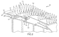
Figure 2 illustrates, in accordance with various embodiments, a partial cross-sectional view of a compressor portion of a gas turbine engine; and -
Figure 3 illustrates, in accordance with various embodiments, a partial cross-sectional view of a compressor portion of a gas turbine engine. - The detailed description of embodiments herein makes reference to the accompanying drawings, which show embodiments by way of illustration. While these embodiments are described in sufficient detail to enable those skilled in the art to practice the inventions, it should be understood that other embodiments may be realized and that logical and mechanical changes may be made without departing from the scope of the inventions. Thus, the detailed description herein is presented for purposes of illustration only and not for limitation. For example, any reference to singular includes plural embodiments, and any reference to more than one component or step may include a singular embodiment or step. Also, any reference to attached, fixed, connected or the like may include permanent, removable, temporary, partial, full and/or any other possible attachment option.
- As used herein, "aft" refers to the direction associated with the tail of an aircraft, or generally, to the direction of exhaust of the gas turbine. As used herein, "forward" and/or "fore" refers to the direction associated with the nose of an aircraft, or generally, to the direction of flight or motion.
- Axial compressors in accordance with the present disclosure may include multiple rotor segments having expansion slots in one or more outer surfaces. The fore end of the expansion slots may include axial seals configured to reduce or prevent unwanted mixing of hotter air from the expansion slots from entering into cooling air passing through cooling channels of the rotor segments,
- Accordingly, with reference to
Figure 1 , agas turbine engine 10 is shown. In general terms,gas turbine engine 10 may comprise acompressor section 12. Air may flow throughcompressor section 12 and into acombustion chamber 14, where the air is mixed with a fuel source and ignited to produce hot combustion gasses. These hot combustion gasses may drive a series of turbine blades within aturbine section 16, which in turn drive, for example, one or more compressor section blades mechanically coupled thereto. - With reference to
Figures 2 and3 ,compressor section 12 may comprise ahigh pressure section 100.High pressure section 100 may comprise, for example, a plurality of rotor segments adjacent to and coupled to each other in the axial direction. For example,high pressure section 100 may comprise afirst rotor segment 102. In various embodiments,first rotor segment 102 may comprise anouter rim 116 having anouter surface 106 and aninner surface 108. - In further embodiments,
first rotor segment 102 may comprise a blade segment having a plurality ofblades 110. Plurality ofblades 110 may be affixed or otherwise coupled toouter surface 106 offirst rotor segment 102. In further embodiments,first rotor segment 102 may comprise a spacer segment having zero blades, or a vane segment including nonrotating vanes to direct air to blades in subsequent segments. - In various embodiments,
high pressure section 100 may further comprise asecond rotor segment 104. For example,second rotor segment 104 may comprise a blade segment having a multiplicity ofblades 110 affixed or otherwise coupled toouter surface 106 ofsecond rotor segment 104.Second rotor segment 104 may be adjacent to and coupled tofirst rotor segment 102. In various embodiments,second rotor segment 104 is positioned aft offirst rotor segment 102. - In various embodiments,
outer rim 116 ofsecond rotor segment 104 comprises anexpansion slot 112.Expansion slot 112 may comprise a radially-projecting opening that passes throughouter surface 106 andinner surface 108 ofouter rim 116. In various embodiments,expansion slot 112 may be positioned between twoblades 110, and may assist reducing hoop stresses onouter rim 116. -
Expansion slot 112 may, for example, extend into acooling channel 120. In various embodiments, one ormore cooling channels 120 may be disposed betweenouter rim 116 and aninner rim 122. In such embodiments,cooling channels 120 may allow cooler air to enter and pass betweeninner rim 122 andouter rim 116, cooling one or both rims. As air passes axially acrossouter surface 106 ofouter rim 116, it rapidly increases in temperature.Expansion slot 112 may undesirably allow hotter air from outside ofouter surface 106 to enter and mix with the cooling air ofcooling channels 120, reducing the cooling ability of the cooling air. Therefore, it may be beneficial to prevent air from escaping the portion ofexpansion slot 112 that extends intocooling channels 120. - In various embodiments,
expansion slot 112 may further comprise and be defined by aradial seal 114. For example, in embodiments in whichexpansion slot 112 extends into coolingchannel 120,radial seal 114 may comprise a structure which reduces the ability of air travelling throughexpansion slot 112 to entercooling channel 120. In various embodiments,radial seal 114 comprises a perimeter of material around the portion ofexpansion slot 112 disposed within coolingchannel 120. In such embodiments,radial seal 114 may segregate the air inexpansion slot 112 from enteringcooling channel 120 in the radial direction. - With reference to
Figure 3 , in various embodiments,high pressure section 100 further comprises anaxial seal 130. For example,axial seal 130 may comprise a structure which reduces the ability of air traveling throughexpansion slot 112 to entercooling channel 120 in the axial direction. - In various embodiments,
axial seal 130 may be positioned fore ofradial seal 114. Stated another way,axial seal 130 is positioned in front of the portion ofexpansion slot 112 which extends belowinner surface 108 ofouter rim 116. For example,axial seal 130 may comprise a fin configuration located fore ofradial seal 114 andexpansion slot 112, such that the point of the fin is pointing towards the incoming air of coolingchannel 120.Axial seal 130 may be configured and shaped to reduce drag and air flow disturbance in the axial direction as well as provide axial sealing. However, any configuration ofaxial seal 130 which segregates air fromexpansion slot 112 from cooling air of coolingchannel 120 is within the scope of the present disclosure. - In various embodiments,
axial seal 130 may be coupled toinner surface 108. For example,axial seal 130 may be integral to and formed withouter rim 116 such thataxial seal 130 extends inwardly frominner surface 108. In further embodiments,axial seal 130 may be formed separately fromouter rim 116 and affixed, attached, or coupled toinner surface 108 ofouter rim 116. - In various embodiments,
high pressure section 100 may comprise multiple rotor segments (such asfirst rotor segment 102 and second rotor segment 104) comprisingmultiple expansion slots 112. In various embodiments,axial seals 130 may be positioned in a rotor segment adjacent to the rotor segment comprisingexpansion slots 112, such that eachaxial seal 130 corresponds with anexpansion slot 112. For example, one or moreaxial seals 130 may be positioned withinfirst rotor segment 102 and correspond with and provide sealing to one ormore expansion slots 112 positioned in second rotor segment 104 (which is adjacent to and aft of first rotor segment 102). Although described in connection with specific examples, any number and configuration ofexpansion slots 112 andaxial seals 130 is within the scope of the present disclosure. - Benefits, other advantages, and solutions to problems have been described herein with regard to specific embodiments. Furthermore, the connecting lines shown in the various figures contained herein are intended to represent functional relationships and/or physical couplings between the various elements. It should be noted that many alternative or additional functional relationships or physical connections may be present in a practical system. However, the benefits, advantages, solutions to problems, and any elements that may cause any benefit, advantage, or solution to occur or become more pronounced are not to be construed as critical, required, or essential features or elements of the inventions. The scope of the inventions is accordingly to be limited by nothing other than the appended claims, in which reference to an element in the singular is not intended to mean "one and only one" unless explicitly so stated, but rather "one or more." Moreover, where a phrase similar to "at least one of A, B, or C" is used in the claims, it is intended that the phrase be interpreted to mean that A alone may be present in an embodiment, B alone may be present in an embodiment, C alone may be present in an embodiment, or that any combination of the elements A, B and C may be present in a single embodiment; for example, A and B, A and C, B and C, or A and B and C. Different cross-hatching is used throughout the figures to denote different parts but not necessarily to denote the same or different materials.
- Systems, methods and apparatus are provided herein. In the detailed description herein, references to "one embodiment," "an embodiment," "an example embodiment," etc., indicate that the embodiment described may include a particular feature, structure, or characteristic, but every embodiment may not necessarily include the particular feature, structure, or characteristic. Moreover, such phrases are not necessarily referring to the same embodiment. Further, when a particular feature, structure, or characteristic is described in connection with an embodiment, it is submitted that it is within the knowledge of one skilled in the art to affect such feature, structure, or characteristic in connection with other embodiments whether or not explicitly described. After reading the description, it will be apparent to one skilled in the relevant art(s) how to implement the disclosure in alternative embodiments.
- Furthermore, no element, component, or method step in the present disclosure is intended to be dedicated to the public regardless of whether the element, component, or method step is explicitly recited in the claims. No claim element herein is to be construed under the provisions of 35 U.S.C. 112(f), unless the element is expressly recited using the phrase "means for." As used herein, the terms "comprises," "comprising," or any other variation thereof, are intended to cover a non-exclusive inclusion, such that a process, method, article, or apparatus that comprises a list of elements does not include only those elements but may include other elements not expressly listed or inherent to such process, method, article, or apparatus.
Claims (11)
- A gas turbine engine compressor comprising:a rotor assembly comprising an outer rim (116) and a blade (110);an expansion slot (112) passing through an outer surface (106) and an inner surface (108) of the outer rim (116), wherein the expansion slot (112) includes a fore end and an aft end; andan axial seal (130) disposed at the fore end of the expansion slot (112).
- The gas turbine engine compressor of claim 1, wherein the rotor assembly comprises a first rotor segment (102) and a second rotor segment (104).
- The gas turbine engine compressor of claim 2, wherein the second rotor segment (104) comprises the blade (110).
- The gas turbine engine compressor of claim 2 or 3, wherein the expansion slot (112) is disposed in the second rotor segment (104).
- The gas turbine engine compressor of claim 2, 3 or 4, wherein the axial seal (130) is coupled to the inner surface (108) of the outer rim (116) in the first rotor segment (102).
- The gas turbine engine compressor of any preceding claim, wherein the axial seal (130) comprises a fin configuration.
- The gas turbine engine compressor of any preceding claim, wherein the axial seal (130) is integral to the inner surface (108) of the outer rim (116).
- The gas turbine engine compressor of any preceding claim, comprising a plurality of expansion slots (112) and axial seals (130), wherein each axial seal (130) corresponds to one expansion slot (112).
- The gas turbine engine compressor of any preceding claim, further comprising a plurality of blades (110), wherein at least one expansion slot (112) is disposed between two of the plurality of blades (110).
- The gas turbine engine compressor of any preceding claim, wherein a radial seal extends into a cooling channel (120) and the axial seal (130) is located within the cooling channel (120).
- A gas turbine engine (10) comprising the gas turbine compressor of any preceding claim, wherein the compressor is an axial high pressure compressor.
Applications Claiming Priority (1)
| Application Number | Priority Date | Filing Date | Title |
|---|---|---|---|
| US201462031627P | 2014-07-31 | 2014-07-31 |
Publications (2)
| Publication Number | Publication Date |
|---|---|
| EP2980358A1 true EP2980358A1 (en) | 2016-02-03 |
| EP2980358B1 EP2980358B1 (en) | 2017-08-30 |
Family
ID=53773285
Family Applications (1)
| Application Number | Title | Priority Date | Filing Date |
|---|---|---|---|
| EP15178880.9A Active EP2980358B1 (en) | 2014-07-31 | 2015-07-29 | Gas turbine engine with axial compressor having improved air sealing |
Country Status (2)
| Country | Link |
|---|---|
| US (1) | US10107127B2 (en) |
| EP (1) | EP2980358B1 (en) |
Cited By (1)
| Publication number | Priority date | Publication date | Assignee | Title |
|---|---|---|---|---|
| EP2985421A1 (en) * | 2014-08-12 | 2016-02-17 | United Technologies Corporation | Assembly, compressor and cooling system |
Citations (2)
| Publication number | Priority date | Publication date | Assignee | Title |
|---|---|---|---|---|
| EP2075411A1 (en) * | 2007-12-28 | 2009-07-01 | United Technologies Corporation | Integrally bladed rotor with slotted outer rim and gas turbine engine comprising such a rotor |
| WO2013139837A1 (en) * | 2012-03-21 | 2013-09-26 | Alstom Technology Ltd | Strip seal and method for designing a strip seal |
Family Cites Families (6)
| Publication number | Priority date | Publication date | Assignee | Title |
|---|---|---|---|---|
| DE19848103A1 (en) * | 1998-10-19 | 2000-04-20 | Asea Brown Boveri | Sealing arrangement |
| JP2002201913A (en) * | 2001-01-09 | 2002-07-19 | Mitsubishi Heavy Ind Ltd | Split wall of gas turbine and shroud |
| DE50211431D1 (en) * | 2001-09-25 | 2008-02-07 | Alstom Technology Ltd | SEALING ARRANGEMENT FOR THE DENSITY PALL REDUCTION WITHIN A FLOW ROTATION MACHINE |
| US7798769B2 (en) * | 2007-02-15 | 2010-09-21 | Siemens Energy, Inc. | Flexible, high-temperature ceramic seal element |
| EP2132414B1 (en) * | 2007-04-05 | 2015-07-01 | Alstom Technology Ltd | Shiplap arrangement |
| DE102009011964A1 (en) * | 2009-03-05 | 2010-09-09 | Mtu Aero Engines Gmbh | Rotor for a turbomachine |
-
2015
- 2015-07-07 US US14/793,468 patent/US10107127B2/en active Active
- 2015-07-29 EP EP15178880.9A patent/EP2980358B1/en active Active
Patent Citations (2)
| Publication number | Priority date | Publication date | Assignee | Title |
|---|---|---|---|---|
| EP2075411A1 (en) * | 2007-12-28 | 2009-07-01 | United Technologies Corporation | Integrally bladed rotor with slotted outer rim and gas turbine engine comprising such a rotor |
| WO2013139837A1 (en) * | 2012-03-21 | 2013-09-26 | Alstom Technology Ltd | Strip seal and method for designing a strip seal |
Cited By (2)
| Publication number | Priority date | Publication date | Assignee | Title |
|---|---|---|---|---|
| EP2985421A1 (en) * | 2014-08-12 | 2016-02-17 | United Technologies Corporation | Assembly, compressor and cooling system |
| US9963972B2 (en) | 2014-08-12 | 2018-05-08 | United Technologies Corporation | Mixing plenum for spoked rotors |
Also Published As
| Publication number | Publication date |
|---|---|
| US10107127B2 (en) | 2018-10-23 |
| US20160032753A1 (en) | 2016-02-04 |
| EP2980358B1 (en) | 2017-08-30 |
Similar Documents
| Publication | Publication Date | Title |
|---|---|---|
| US10364749B2 (en) | Cooling air heat exchanger scoop | |
| US10060351B2 (en) | De-icing device for a splitter nose of an axial turbine engine compressor | |
| US8821122B2 (en) | Integrally bladed rotor disk for a turbine | |
| US9988934B2 (en) | Gas turbine engines including channel-cooled hooks for retaining a part relative to an engine casing structure | |
| US20090148277A1 (en) | Gas Turbine Engines and Related Systems Involving Blade Outer Air Seals | |
| US20110070074A1 (en) | Gas turbine with a shroud and labyrinth-type sealing arrangement | |
| US9410427B2 (en) | Compressor power and torque transmitting hub | |
| US8985942B2 (en) | Turbine exhaust case duct | |
| US10815806B2 (en) | Engine component with insert | |
| US7334985B2 (en) | Shroud with aero-effective cooling | |
| US9995173B2 (en) | Ducting platform cover plate | |
| EP3048263A1 (en) | Active clearance control systems | |
| KR20160076474A (en) | Engine and method for operating said engine | |
| US20140023487A1 (en) | Gas turbine engine outer case with contoured bleed boss | |
| US10669870B2 (en) | Vane for jet engine mid-turbine frame | |
| US9988935B2 (en) | Gas turbine engine with axial compressor with internal cooling pathways | |
| US10107127B2 (en) | Gas turbine engine with axial compressor having improved air sealing | |
| CN106194276B (en) | Compressor assembly and airfoil component | |
| EP3825520B1 (en) | Assembly with vane and sealing member for a gas turbine engine | |
| CA2998277C (en) | Nozzle sector for a turbine engine with differentially cooled blades | |
| US9879537B2 (en) | Gas turbine engine axial compressor rear hub | |
| US20250382893A1 (en) | Shrouded turbine assembly for gas turbine engine | |
| WO2016033465A1 (en) | Gas turbine blade tip shroud flow guiding features | |
| US12546229B1 (en) | Gas turbine engine rotor stage with seal members | |
| US20190003318A1 (en) | Turbomachine rotor blade |
Legal Events
| Date | Code | Title | Description |
|---|---|---|---|
| PUAI | Public reference made under article 153(3) epc to a published international application that has entered the european phase |
Free format text: ORIGINAL CODE: 0009012 |
|
| AK | Designated contracting states |
Kind code of ref document: A1 Designated state(s): AL AT BE BG CH CY CZ DE DK EE ES FI FR GB GR HR HU IE IS IT LI LT LU LV MC MK MT NL NO PL PT RO RS SE SI SK SM TR |
|
| AX | Request for extension of the european patent |
Extension state: BA ME |
|
| 17P | Request for examination filed |
Effective date: 20160801 |
|
| RBV | Designated contracting states (corrected) |
Designated state(s): AL AT BE BG CH CY CZ DE DK EE ES FI FR GB GR HR HU IE IS IT LI LT LU LV MC MK MT NL NO PL PT RO RS SE SI SK SM TR |
|
| RAP1 | Party data changed (applicant data changed or rights of an application transferred) |
Owner name: UNITED TECHNOLOGIES CORPORATION |
|
| GRAP | Despatch of communication of intention to grant a patent |
Free format text: ORIGINAL CODE: EPIDOSNIGR1 |
|
| STAA | Information on the status of an ep patent application or granted ep patent |
Free format text: STATUS: GRANT OF PATENT IS INTENDED |
|
| RIC1 | Information provided on ipc code assigned before grant |
Ipc: F01D 11/00 20060101ALI20170215BHEP Ipc: F01D 5/22 20060101AFI20170215BHEP Ipc: F01D 11/04 20060101ALI20170215BHEP Ipc: F01D 5/24 20060101ALI20170215BHEP Ipc: F01D 5/18 20060101ALI20170215BHEP Ipc: F01D 5/06 20060101ALI20170215BHEP |
|
| INTG | Intention to grant announced |
Effective date: 20170310 |
|
| GRAS | Grant fee paid |
Free format text: ORIGINAL CODE: EPIDOSNIGR3 |
|
| GRAA | (expected) grant |
Free format text: ORIGINAL CODE: 0009210 |
|
| STAA | Information on the status of an ep patent application or granted ep patent |
Free format text: STATUS: THE PATENT HAS BEEN GRANTED |
|
| AK | Designated contracting states |
Kind code of ref document: B1 Designated state(s): AL AT BE BG CH CY CZ DE DK EE ES FI FR GB GR HR HU IE IS IT LI LT LU LV MC MK MT NL NO PL PT RO RS SE SI SK SM TR |
|
| REG | Reference to a national code |
Ref country code: GB Ref legal event code: FG4D |
|
| REG | Reference to a national code |
Ref country code: CH Ref legal event code: EP |
|
| REG | Reference to a national code |
Ref country code: AT Ref legal event code: REF Ref document number: 923763 Country of ref document: AT Kind code of ref document: T Effective date: 20170915 |
|
| REG | Reference to a national code |
Ref country code: IE Ref legal event code: FG4D |
|
| REG | Reference to a national code |
Ref country code: DE Ref legal event code: R096 Ref document number: 602015004416 Country of ref document: DE |
|
| REG | Reference to a national code |
Ref country code: NL Ref legal event code: MP Effective date: 20170830 |
|
| REG | Reference to a national code |
Ref country code: LT Ref legal event code: MG4D |
|
| REG | Reference to a national code |
Ref country code: AT Ref legal event code: MK05 Ref document number: 923763 Country of ref document: AT Kind code of ref document: T Effective date: 20170830 |
|
| PG25 | Lapsed in a contracting state [announced via postgrant information from national office to epo] |
Ref country code: SE Free format text: LAPSE BECAUSE OF FAILURE TO SUBMIT A TRANSLATION OF THE DESCRIPTION OR TO PAY THE FEE WITHIN THE PRESCRIBED TIME-LIMIT Effective date: 20170830 Ref country code: FI Free format text: LAPSE BECAUSE OF FAILURE TO SUBMIT A TRANSLATION OF THE DESCRIPTION OR TO PAY THE FEE WITHIN THE PRESCRIBED TIME-LIMIT Effective date: 20170830 Ref country code: LT Free format text: LAPSE BECAUSE OF FAILURE TO SUBMIT A TRANSLATION OF THE DESCRIPTION OR TO PAY THE FEE WITHIN THE PRESCRIBED TIME-LIMIT Effective date: 20170830 Ref country code: AT Free format text: LAPSE BECAUSE OF FAILURE TO SUBMIT A TRANSLATION OF THE DESCRIPTION OR TO PAY THE FEE WITHIN THE PRESCRIBED TIME-LIMIT Effective date: 20170830 Ref country code: HR Free format text: LAPSE BECAUSE OF FAILURE TO SUBMIT A TRANSLATION OF THE DESCRIPTION OR TO PAY THE FEE WITHIN THE PRESCRIBED TIME-LIMIT Effective date: 20170830 Ref country code: NO Free format text: LAPSE BECAUSE OF FAILURE TO SUBMIT A TRANSLATION OF THE DESCRIPTION OR TO PAY THE FEE WITHIN THE PRESCRIBED TIME-LIMIT Effective date: 20171130 |
|
| PG25 | Lapsed in a contracting state [announced via postgrant information from national office to epo] |
Ref country code: RS Free format text: LAPSE BECAUSE OF FAILURE TO SUBMIT A TRANSLATION OF THE DESCRIPTION OR TO PAY THE FEE WITHIN THE PRESCRIBED TIME-LIMIT Effective date: 20170830 Ref country code: LV Free format text: LAPSE BECAUSE OF FAILURE TO SUBMIT A TRANSLATION OF THE DESCRIPTION OR TO PAY THE FEE WITHIN THE PRESCRIBED TIME-LIMIT Effective date: 20170830 Ref country code: ES Free format text: LAPSE BECAUSE OF FAILURE TO SUBMIT A TRANSLATION OF THE DESCRIPTION OR TO PAY THE FEE WITHIN THE PRESCRIBED TIME-LIMIT Effective date: 20170830 Ref country code: IS Free format text: LAPSE BECAUSE OF FAILURE TO SUBMIT A TRANSLATION OF THE DESCRIPTION OR TO PAY THE FEE WITHIN THE PRESCRIBED TIME-LIMIT Effective date: 20171230 Ref country code: GR Free format text: LAPSE BECAUSE OF FAILURE TO SUBMIT A TRANSLATION OF THE DESCRIPTION OR TO PAY THE FEE WITHIN THE PRESCRIBED TIME-LIMIT Effective date: 20171201 Ref country code: BG Free format text: LAPSE BECAUSE OF FAILURE TO SUBMIT A TRANSLATION OF THE DESCRIPTION OR TO PAY THE FEE WITHIN THE PRESCRIBED TIME-LIMIT Effective date: 20171130 |
|
| PG25 | Lapsed in a contracting state [announced via postgrant information from national office to epo] |
Ref country code: NL Free format text: LAPSE BECAUSE OF FAILURE TO SUBMIT A TRANSLATION OF THE DESCRIPTION OR TO PAY THE FEE WITHIN THE PRESCRIBED TIME-LIMIT Effective date: 20170830 |
|
| PG25 | Lapsed in a contracting state [announced via postgrant information from national office to epo] |
Ref country code: CZ Free format text: LAPSE BECAUSE OF FAILURE TO SUBMIT A TRANSLATION OF THE DESCRIPTION OR TO PAY THE FEE WITHIN THE PRESCRIBED TIME-LIMIT Effective date: 20170830 Ref country code: DK Free format text: LAPSE BECAUSE OF FAILURE TO SUBMIT A TRANSLATION OF THE DESCRIPTION OR TO PAY THE FEE WITHIN THE PRESCRIBED TIME-LIMIT Effective date: 20170830 Ref country code: PL Free format text: LAPSE BECAUSE OF FAILURE TO SUBMIT A TRANSLATION OF THE DESCRIPTION OR TO PAY THE FEE WITHIN THE PRESCRIBED TIME-LIMIT Effective date: 20170830 Ref country code: RO Free format text: LAPSE BECAUSE OF FAILURE TO SUBMIT A TRANSLATION OF THE DESCRIPTION OR TO PAY THE FEE WITHIN THE PRESCRIBED TIME-LIMIT Effective date: 20170830 |
|
| PG25 | Lapsed in a contracting state [announced via postgrant information from national office to epo] |
Ref country code: IT Free format text: LAPSE BECAUSE OF FAILURE TO SUBMIT A TRANSLATION OF THE DESCRIPTION OR TO PAY THE FEE WITHIN THE PRESCRIBED TIME-LIMIT Effective date: 20170830 Ref country code: SM Free format text: LAPSE BECAUSE OF FAILURE TO SUBMIT A TRANSLATION OF THE DESCRIPTION OR TO PAY THE FEE WITHIN THE PRESCRIBED TIME-LIMIT Effective date: 20170830 Ref country code: SK Free format text: LAPSE BECAUSE OF FAILURE TO SUBMIT A TRANSLATION OF THE DESCRIPTION OR TO PAY THE FEE WITHIN THE PRESCRIBED TIME-LIMIT Effective date: 20170830 Ref country code: EE Free format text: LAPSE BECAUSE OF FAILURE TO SUBMIT A TRANSLATION OF THE DESCRIPTION OR TO PAY THE FEE WITHIN THE PRESCRIBED TIME-LIMIT Effective date: 20170830 |
|
| REG | Reference to a national code |
Ref country code: DE Ref legal event code: R097 Ref document number: 602015004416 Country of ref document: DE |
|
| REG | Reference to a national code |
Ref country code: FR Ref legal event code: PLFP Year of fee payment: 4 |
|
| PLBE | No opposition filed within time limit |
Free format text: ORIGINAL CODE: 0009261 |
|
| STAA | Information on the status of an ep patent application or granted ep patent |
Free format text: STATUS: NO OPPOSITION FILED WITHIN TIME LIMIT |
|
| 26N | No opposition filed |
Effective date: 20180531 |
|
| PG25 | Lapsed in a contracting state [announced via postgrant information from national office to epo] |
Ref country code: SI Free format text: LAPSE BECAUSE OF FAILURE TO SUBMIT A TRANSLATION OF THE DESCRIPTION OR TO PAY THE FEE WITHIN THE PRESCRIBED TIME-LIMIT Effective date: 20170830 |
|
| REG | Reference to a national code |
Ref country code: CH Ref legal event code: PL |
|
| PG25 | Lapsed in a contracting state [announced via postgrant information from national office to epo] |
Ref country code: MC Free format text: LAPSE BECAUSE OF FAILURE TO SUBMIT A TRANSLATION OF THE DESCRIPTION OR TO PAY THE FEE WITHIN THE PRESCRIBED TIME-LIMIT Effective date: 20170830 Ref country code: LU Free format text: LAPSE BECAUSE OF NON-PAYMENT OF DUE FEES Effective date: 20180729 |
|
| REG | Reference to a national code |
Ref country code: BE Ref legal event code: MM Effective date: 20180731 |
|
| PG25 | Lapsed in a contracting state [announced via postgrant information from national office to epo] |
Ref country code: LI Free format text: LAPSE BECAUSE OF NON-PAYMENT OF DUE FEES Effective date: 20180731 Ref country code: CH Free format text: LAPSE BECAUSE OF NON-PAYMENT OF DUE FEES Effective date: 20180731 |
|
| REG | Reference to a national code |
Ref country code: IE Ref legal event code: MM4A |
|
| PG25 | Lapsed in a contracting state [announced via postgrant information from national office to epo] |
Ref country code: BE Free format text: LAPSE BECAUSE OF NON-PAYMENT OF DUE FEES Effective date: 20180731 |
|
| PG25 | Lapsed in a contracting state [announced via postgrant information from national office to epo] |
Ref country code: IE Free format text: LAPSE BECAUSE OF NON-PAYMENT OF DUE FEES Effective date: 20180729 |
|
| PG25 | Lapsed in a contracting state [announced via postgrant information from national office to epo] |
Ref country code: MT Free format text: LAPSE BECAUSE OF NON-PAYMENT OF DUE FEES Effective date: 20180729 |
|
| PG25 | Lapsed in a contracting state [announced via postgrant information from national office to epo] |
Ref country code: TR Free format text: LAPSE BECAUSE OF FAILURE TO SUBMIT A TRANSLATION OF THE DESCRIPTION OR TO PAY THE FEE WITHIN THE PRESCRIBED TIME-LIMIT Effective date: 20170830 |
|
| PG25 | Lapsed in a contracting state [announced via postgrant information from national office to epo] |
Ref country code: PT Free format text: LAPSE BECAUSE OF FAILURE TO SUBMIT A TRANSLATION OF THE DESCRIPTION OR TO PAY THE FEE WITHIN THE PRESCRIBED TIME-LIMIT Effective date: 20170830 |
|
| PG25 | Lapsed in a contracting state [announced via postgrant information from national office to epo] |
Ref country code: HU Free format text: LAPSE BECAUSE OF FAILURE TO SUBMIT A TRANSLATION OF THE DESCRIPTION OR TO PAY THE FEE WITHIN THE PRESCRIBED TIME-LIMIT; INVALID AB INITIO Effective date: 20150729 Ref country code: MK Free format text: LAPSE BECAUSE OF NON-PAYMENT OF DUE FEES Effective date: 20170830 Ref country code: CY Free format text: LAPSE BECAUSE OF FAILURE TO SUBMIT A TRANSLATION OF THE DESCRIPTION OR TO PAY THE FEE WITHIN THE PRESCRIBED TIME-LIMIT Effective date: 20170830 |
|
| PG25 | Lapsed in a contracting state [announced via postgrant information from national office to epo] |
Ref country code: AL Free format text: LAPSE BECAUSE OF FAILURE TO SUBMIT A TRANSLATION OF THE DESCRIPTION OR TO PAY THE FEE WITHIN THE PRESCRIBED TIME-LIMIT Effective date: 20170830 |
|
| REG | Reference to a national code |
Ref country code: DE Ref legal event code: R081 Ref document number: 602015004416 Country of ref document: DE Owner name: RAYTHEON TECHNOLOGIES CORPORATION (N.D.GES.D.S, US Free format text: FORMER OWNER: UNITED TECHNOLOGIES CORPORATION, FARMINGTON, CONN., US Ref country code: DE Ref legal event code: R081 Ref document number: 602015004416 Country of ref document: DE Owner name: RTX CORPORATION (N.D.GES.D. STAATES DELAWARE),, US Free format text: FORMER OWNER: UNITED TECHNOLOGIES CORPORATION, FARMINGTON, CONN., US |
|
| P01 | Opt-out of the competence of the unified patent court (upc) registered |
Effective date: 20230520 |
|
| PGFP | Annual fee paid to national office [announced via postgrant information from national office to epo] |
Ref country code: GB Payment date: 20250619 Year of fee payment: 11 |
|
| PGFP | Annual fee paid to national office [announced via postgrant information from national office to epo] |
Ref country code: FR Payment date: 20250620 Year of fee payment: 11 |
|
| PGFP | Annual fee paid to national office [announced via postgrant information from national office to epo] |
Ref country code: DE Payment date: 20250620 Year of fee payment: 11 |
|
| REG | Reference to a national code |
Ref country code: DE Ref legal event code: R081 Ref document number: 602015004416 Country of ref document: DE Owner name: RTX CORPORATION (N.D.GES.D. STAATES DELAWARE),, US Free format text: FORMER OWNER: RAYTHEON TECHNOLOGIES CORPORATION (N.D.GES.D.STAATES DELAWARE), ARLINGTON, VA, US |