EP2979969A1 - Power transmission system of electric bicycle - Google Patents
Power transmission system of electric bicycle Download PDFInfo
- Publication number
- EP2979969A1 EP2979969A1 EP15166491.9A EP15166491A EP2979969A1 EP 2979969 A1 EP2979969 A1 EP 2979969A1 EP 15166491 A EP15166491 A EP 15166491A EP 2979969 A1 EP2979969 A1 EP 2979969A1
- Authority
- EP
- European Patent Office
- Prior art keywords
- gear
- power transmission
- transmission system
- driving gear
- following
- Prior art date
- Legal status (The legal status is an assumption and is not a legal conclusion. Google has not performed a legal analysis and makes no representation as to the accuracy of the status listed.)
- Withdrawn
Links
- 230000005540 biological transmission Effects 0.000 title claims abstract description 69
- 230000008901 benefit Effects 0.000 description 3
- 238000010586 diagram Methods 0.000 description 2
- 238000000034 method Methods 0.000 description 2
- 238000012986 modification Methods 0.000 description 2
- 230000004048 modification Effects 0.000 description 2
- 230000004308 accommodation Effects 0.000 description 1
- 238000007792 addition Methods 0.000 description 1
- 238000006467 substitution reaction Methods 0.000 description 1
Images


Classifications
-
- B—PERFORMING OPERATIONS; TRANSPORTING
- B62—LAND VEHICLES FOR TRAVELLING OTHERWISE THAN ON RAILS
- B62M—RIDER PROPULSION OF WHEELED VEHICLES OR SLEDGES; POWERED PROPULSION OF SLEDGES OR SINGLE-TRACK CYCLES; TRANSMISSIONS SPECIALLY ADAPTED FOR SUCH VEHICLES
- B62M11/00—Transmissions characterised by the use of interengaging toothed wheels or frictionally-engaging wheels
- B62M11/02—Transmissions characterised by the use of interengaging toothed wheels or frictionally-engaging wheels of unchangeable ratio
-
- B—PERFORMING OPERATIONS; TRANSPORTING
- B62—LAND VEHICLES FOR TRAVELLING OTHERWISE THAN ON RAILS
- B62M—RIDER PROPULSION OF WHEELED VEHICLES OR SLEDGES; POWERED PROPULSION OF SLEDGES OR SINGLE-TRACK CYCLES; TRANSMISSIONS SPECIALLY ADAPTED FOR SUCH VEHICLES
- B62M6/00—Rider propulsion of wheeled vehicles with additional source of power, e.g. combustion engine or electric motor
- B62M6/40—Rider propelled cycles with auxiliary electric motor
- B62M6/55—Rider propelled cycles with auxiliary electric motor power-driven at crank shafts parts
Definitions
- the present disclosure relates to a power transmission system of an electric bicycle (or an e-bike).
- a bicycle is configured such that a front wheel as a steering wheel and a rear wheel as a driving wheel are disposed linearly in front and rear sides of a frame, and moves forwards when a user works a pedal interworking with the rear wheel to rotate the rear wheel.
- a power transmission system such as a chain or a gear, transmitting power generated in the peal to the rear wheel is installed in such a bicycle.
- a chain type power transmission system includes a driving sprocket installed on one side of a pedal, a passive sprocket having a diameter smaller than that of the driving sprocket and installed in the rear wheel as a driving wheel, and a chain connecting the driving sprocket and the passive sprocket.
- the driving sprocket integrally installed with the pedal rotates and the rear wheel connected to the passive sprocket by the chain also simultaneously rotates, moving the bicycle forwards.
- a motor driven by a battery is used in an electric bicycle, and the electric bicycle is configured such that the user may select to run only with force for working a pedal, to run with force of a motor driven by a battery, or to run using the both.
- Patent Document 1 Korean Patent Laid-Open Publication No. 2012-0132593
- An aspect of the present disclosure may provide a power transmission system of an electric bicycle which is small in size and light in weight.
- a power transmission system of an electric bicycle may include: a first following gear receiving power from a rotational shaft of a driving motor; a first driving gear engaged with the first following gear to receive power; a second following gear installed in a first gear shaft in which the first driving gear is installed; a second driving gear engaged with the second following gear to receive power; a third following gear installed in a second gear shaft in which the second driving gear is installed; and a third driving gear engaged with the third following gear to receive power, and installed in a pedal shaft.
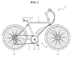
- FIG. 1 is a diagram illustrating an electric bicycle in which a power transmission system of an electric bicycle according to an exemplary embodiment of the present disclosure is used
- FIG. 2 is a perspective view illustrating a case in which the power transmission system of an electric bicycle according to an exemplary embodiment of the present disclosure is accommodated
- FIG. 3 is a front perspective view illustrating the power transmission system of an electric bicycle according to an exemplary embodiment of the present disclosure.
- a power transmission system 100 of an electric bicycle may include a first following gear 120, a first driving gear 130, a second following gear 150, a second driving gear 160, a third following gear 170, and a third driving gear 180. Also, a power transmission system 100 of an electric bicycle according to an exemplary embodiment of the present disclosure may further include a first power transmission unit and a second power transmission unit.
- the power transmission system 100 may include the pedal 14 and the driving motor 12.
- the pedal 14 rotates and transmits rotary power to the chain 15.
- the driving motor 12 is connected to a power supply unit, and when power is supplied, a rotational shaft 12a of the driving motor 12 rotates to transmit rotary power to the chain 15.
- the driving motor 12 assists to enable the electric bicycle 10 to easily run on a hill, or the like, even though the user exerts a small amount of force to the petal 14.
- the power transmission system 100 of the electric bicycle may further include a case 110 having an accommodation space therein to accommodate a portion or the entirety of components of the power transmission system 100 to protect the same.
- FIG. 4 is a rear perspective view illustrating the power transmission system of an electric bicycle according to an exemplary embodiment of the present disclosure.
- the first following gear 120 receives power from the rotational shaft 12a of the driving motor 12.
- the first following gear 120 is installed in the rotational shaft 12a to co-rotate with the rotational shaft 12a.
- the first following gear 120 may be coupled to an end portion of the rotational shaft 12a.
- the first following gear 120 may be configured as a pinion, for example.
- a rotational shaft bearing 12b is installed in the rotational shaft 12a to support the rotational shaft 12a.
- an outer circumferential surface of the rotational shaft bearing 12b may be fixed to the case 110 and an inner circumferential surface thereof may be installed in the rotational shaft 11 a, for example.
- the first driving gear 130 may be engaged with the first following gear 120 to receive power.
- the first driving gear 130 is provided on one side of a first gear shaft 131 and rotate according to rotation of the following gear 120. Also, the first driving gear 130 may be configured as a wheel gear.
- the second following gear 150 is installed in the first gear shaft 131 in which the first driving gear 130 is installed, so as to co-rotate with the first gear shaft 131.
- the second following gear 150 may be provided on the other side of the first gear shaft 131 and co-rotate according to rotation of the first driving gear 130 to receive power.
- the second following gear 150 may be configured as a pinion, for example.
- the second driving gear 160 may be engaged with the second following gear 150 to receive power.
- the second driving gear 160 may be positioned on one side of the second gear shaft 161 and rotate according to rotation of the second following gear 150. Also, the second driving gear 160 may be configured as a wheel gear.
- the third following gear 170 may be installed in the second gear shaft 161 in which the second driving gear 160 is installed, so as to co-rotate with the second gear shaft 161.
- the third following gear 170 may be provided on the other wide of the second gear shaft 16 and co-rotate according to rotation of the second driving gear 160 to receive power.
- the third following gear 170 may be configured as a pinion, for example.
- the third driving gear 180 is engaged with the third following gear 170 to receive power.
- the third driving gear 180 is installed in a pedal shaft 13 and rotates according to rotation of the third following gear 170. Also, the third driving gear 180 may be configured as a wheel gear.
- a pedal shaft bearing 13b is installed in the pedal shaft 13 to support the pedal shaft 13.
- an outer circumferential surface of the pedal shaft bearing 13b may be fixed to the case 110 and an inner circumferential surface thereof may be installed in the pedal shaft 13, for example.
- the first following gear 120 and the first driving gear 130 may have a helical gear form so as to be engaged with each other. Also, the first following gear 120 may be formed to be smaller than the first driving gear 130. Here, the first following gear 120 may be formed to have a gear ratio of 1/2 or smaller of that of the first driving gear 130, but the gear ratio of the first following gear 120 to the first driving gear 130 in the power transmission system of the electric bicycle is not limited thereto.
- the second following gear 150 and the second driving gear 160 may have a helical gear form so as to be engaged with each other, for example. Also, the second following gear 150 may be formed to be smaller than the second driving gear 160. Here, the second following gear 150 may be formed to have a gear ratio of 1/2 or smaller of that of the second driving gear 160, but the gear ratio of the second following gear 150 to the second driving gear 160 in the power transmission system of the electric bicycle is not limited thereto.
- the third following gear 160 and the third driving gear 180 may have a spur gear form so as to be engaged with each other.
- the third following gear 170 may be formed to be smaller than the third driving gear 180.
- the third following gear 170 may be formed to have a gear ratio of 1/2 or smaller of that of the third driving gear 180, but the gear ratio of the third following gear 170 to the third driving gear 180 in the power transmission system of the electric bicycle according to an exemplary embodiment of the present disclosure is not limited thereto.
- FIG. 5 is a cutaway perspective view illustrating a structure in which a unidirectional clutch is installed in the power transmission system of an electric bicycle according to an exemplary embodiment of the present disclosure
- FIG. 6 is a perspective view illustrating the unidirectional clutch in the power transmission system of an electric bicycle according to an exemplary embodiment of the present disclosure.
- the first power transmission unit is provided between the first driving gear 130 and the first gear shaft 131 to transmit power only in one direction.
- the first power transmission unit is configured as a uni-directional clutch 140 and transmits power from the first driving gear 130 only to the first gear shaft 131.
- the one direction may be a direction opposite to a rotational direction of the rotational shaft 12a of the driving motor 12.
- the one direction may be a counterclockwise direction, for example, but one direction in the power transmission system 100 of an electric bicycle according to an exemplary embodiment of the present disclosure is not limited to the counterclockwise direction.
- the uni-directional clutch 140 may be configured as a cylindrical clutch, for example.
- the technique of transmitting power in one direction through the uni-directional clutch 140 is a known technique, and thus, a detailed description thereof will be omitted.
- FIG. 7 is a perspective view illustrating a structure in which a ratchet is installed in the power transmission system of an electric bicycle according to an exemplary embodiment of the present disclosure
- FIG. 8 is a perspective view illustrating the ratchet in power transmission system of an electric bicycle according to an exemplary embodiment of the present disclosure
- FIG. 9 is a cross-sectional view illustrating the ratchet in power transmission system of an electric bicycle according to an exemplary embodiment of the present disclosure.
- the second power transmission unit is provided between the third driving gear 180 and the pedal shaft 13 and transmits power only in one direction.
- the second power transmission unit is configured as a ratchet 190 to transmit power from the third driving gear 180 only to the pedal shaft 13.
- the ratchet 190 may co-rotate with the third driving gear 180, and may transmit rotary power from the third driving gear 180 in one direction to the pedal shaft 13 and may not transmit rotary power of rotation from the pedal shaft 13 in the other direction, to the third driving gear 180. That is, when rotating in one direction, the ratchet 190 transmits power, and when rotating in the other direction, the ratchet 190 runs idle, and thus, power is not transmitted.
- the ratchet 190 rotates the chain 15 according to rotation of the pedal shaft 13 based on pedal effort generated as the user works the pedal 14, and transmits power in a direction in which the front wheel 16 and the rear wheel 17 rotate (refer to FIG. 1 ).
- the ratchet 190 may include a support member 191 having protrusions formed on an inner circumferential surface thereof, a spring 192 positioned on the inner circumferential surface of the support member 191 and having protrusions formed on an outer circumferential surface thereof, and a pawl 193 provided in the spring 192.
- the power transmission system 100 of the electric bicycle has a 3-stage deceleration structure, thus having a reduced size and weight.
Landscapes
- Engineering & Computer Science (AREA)
- Chemical & Material Sciences (AREA)
- Combustion & Propulsion (AREA)
- Transportation (AREA)
- Mechanical Engineering (AREA)
- Electric Propulsion And Braking For Vehicles (AREA)
- Gear Transmission (AREA)
Abstract
There is provided a power transmission system of an electric bicycle (10), including: a first following gear (120) receiving power from a rotational shaft (12a) of a driving motor (12); a first driving gear (130) engaged with the first following gear (120) to receive power; a second following gear (140) installed in a first gear shaft (131) in which the first driving gear (130) is installed; a second driving gear (160) engaged with the second following gear (140) to receive power; a third following gear (170) installed in a second gear shaft (161) in which the second driving gear (160) is installed; and a third driving gear (180) engaged with the third following gear (170) to receive power, and installed in a pedal shaft (13).
Description
- This application claims the benefit of Korean Patent Application No.
10-2014-0098421, filed on July 31, 2014 - The present disclosure relates to a power transmission system of an electric bicycle (or an e-bike).
- A bicycle is configured such that a front wheel as a steering wheel and a rear wheel as a driving wheel are disposed linearly in front and rear sides of a frame, and moves forwards when a user works a pedal interworking with the rear wheel to rotate the rear wheel. A power transmission system, such as a chain or a gear, transmitting power generated in the peal to the rear wheel is installed in such a bicycle.
- In particular, a chain type power transmission system includes a driving sprocket installed on one side of a pedal, a passive sprocket having a diameter smaller than that of the driving sprocket and installed in the rear wheel as a driving wheel, and a chain connecting the driving sprocket and the passive sprocket.
- Thus, with such a configuration, when a user works a pedal, the driving sprocket integrally installed with the pedal rotates and the rear wheel connected to the passive sprocket by the chain also simultaneously rotates, moving the bicycle forwards.
- Such a bicycle runs using a petal effort based on user pedaling, and there is no difficulty in running on a flatland, but a great amount of force is required when the user goes up a slope, such as a hill, on the bicycle.
- In order to solve the problem, an electric bicycle including a motor to run using driving force of the motor in addition to the user's pedal effort has been developed.
- Namely, a motor driven by a battery is used in an electric bicycle, and the electric bicycle is configured such that the user may select to run only with force for working a pedal, to run with force of a motor driven by a battery, or to run using the both.
- (Patent Document 1) Korean Patent Laid-Open Publication No.
2012-0132593 - An aspect of the present disclosure may provide a power transmission system of an electric bicycle which is small in size and light in weight.
- According to an aspect of the present disclosure, a power transmission system of an electric bicycle may include: a first following gear receiving power from a rotational shaft of a driving motor; a first driving gear engaged with the first following gear to receive power; a second following gear installed in a first gear shaft in which the first driving gear is installed; a second driving gear engaged with the second following gear to receive power; a third following gear installed in a second gear shaft in which the second driving gear is installed; and a third driving gear engaged with the third following gear to receive power, and installed in a pedal shaft.
- The above and other aspects, features and other advantages of the present disclosure will be more clearly understood from the following detailed description taken in conjunction with the accompanying drawings, in which:
-
FIG. 1 is a diagram illustrating an electric bicycle in which a power transmission system of an electric bicycle according to an exemplary embodiment of the present disclosure is used; -
FIG. 2 is a perspective view illustrating a case in which the power transmission system of an electric bicycle according to an exemplary embodiment of the present disclosure is accommodated; -
FIG. 3 is a front perspective view illustrating the power transmission system of an electric bicycle according to an exemplary embodiment of the present disclosure; -
FIG. 4 is a rear perspective view illustrating the power transmission system of an electric bicycle according to an exemplary embodiment of the present disclosure; -
FIG. 5 is a cutaway perspective view illustrating a structure in which a uni-directional clutch is installed in the power transmission system of an electric bicycle according to an exemplary embodiment of the present disclosure; -
FIG. 6 is a perspective view illustrating the unidirectional clutch in the power transmission system of an electric bicycle according to an exemplary embodiment of the present disclosure; -
FIG. 7 is a perspective view illustrating a structure in which a ratchet is installed in the power transmission system of an electric bicycle according to an exemplary embodiment of the present disclosure; -
FIG. 8 is a perspective view illustrating the ratchet in power transmission system of an electric bicycle according to an exemplary embodiment of the present disclosure; and -
FIG. 9 is a cross-sectional view illustrating the ratchet in power transmission system of an electric bicycle according to an exemplary embodiment of the present disclosure. - The objects, features and advantages of the present disclosure will be more clearly understood from the following detailed description of the exemplary embodiments taken in conjunction with the accompanying drawings. Throughout the accompanying drawings, the same reference numerals are used to designate the same or similar components, and redundant descriptions thereof are omitted. Further, in the following description, the terms "first," "second," "one side," "the other side" and the like are used to differentiate a certain component from other components, but the configuration of such components should not be construed to be limited by the terms. Further, in the description of the present disclosure, when it is determined that the detailed description of the related art would obscure the gist of the present disclosure, the description thereof will be omitted.
- Hereinafter, exemplary embodiments of the present disclosure will be described in detail with reference to the accompanying drawings.
-
FIG. 1 is a diagram illustrating an electric bicycle in which a power transmission system of an electric bicycle according to an exemplary embodiment of the present disclosure is used,FIG. 2 is a perspective view illustrating a case in which the power transmission system of an electric bicycle according to an exemplary embodiment of the present disclosure is accommodated, andFIG. 3 is a front perspective view illustrating the power transmission system of an electric bicycle according to an exemplary embodiment of the present disclosure. - Referring to
FIG. 3 , apower transmission system 100 of an electric bicycle according to an exemplary embodiment of the present disclosure may include a first followinggear 120, afirst driving gear 130, a second followinggear 150, asecond driving gear 160, a third followinggear 170, and athird driving gear 180. Also, apower transmission system 100 of an electric bicycle according to an exemplary embodiment of the present disclosure may further include a first power transmission unit and a second power transmission unit. - Referring to
FIG. 1 , in anelectric bicycle 10, afront wheel 16 and arear wheel 17 are supported by aframe 11, and achain 15 rotating according to a pedal effort of thepedal 14 or power transmission from a drivingmotor 12 is engaged with therear wheel 17. Here, thepower transmission system 100 may include thepedal 14 and thedriving motor 12. Here, when a force is applied to thepedal 14 by the user, thepedal 14 rotates and transmits rotary power to thechain 15. Also, thedriving motor 12 is connected to a power supply unit, and when power is supplied, arotational shaft 12a of thedriving motor 12 rotates to transmit rotary power to thechain 15. Here, when the user exerts a force to thepedal 14 to run theelectric bicycle 10, the drivingmotor 12 assists to enable theelectric bicycle 10 to easily run on a hill, or the like, even though the user exerts a small amount of force to thepetal 14. - Referring to
FIG. 2 , thepower transmission system 100 of the electric bicycle according to an exemplary embodiment of the present disclosure may further include acase 110 having an accommodation space therein to accommodate a portion or the entirety of components of thepower transmission system 100 to protect the same. -
FIG. 4 is a rear perspective view illustrating the power transmission system of an electric bicycle according to an exemplary embodiment of the present disclosure. - Referring to
FIGS. 3 and4 , the first followinggear 120 receives power from therotational shaft 12a of thedriving motor 12. Here, the first followinggear 120 is installed in therotational shaft 12a to co-rotate with therotational shaft 12a. Here, the first followinggear 120 may be coupled to an end portion of therotational shaft 12a. - Also, the first following
gear 120 may be configured as a pinion, for example. - Meanwhile, a rotational shaft bearing 12b is installed in the
rotational shaft 12a to support therotational shaft 12a. Here, an outer circumferential surface of the rotational shaft bearing 12b may be fixed to thecase 110 and an inner circumferential surface thereof may be installed in the rotational shaft 11 a, for example. - The
first driving gear 130 may be engaged with the first followinggear 120 to receive power. - Here, the
first driving gear 130 is provided on one side of afirst gear shaft 131 and rotate according to rotation of the followinggear 120. Also, thefirst driving gear 130 may be configured as a wheel gear. - The second following
gear 150 is installed in thefirst gear shaft 131 in which thefirst driving gear 130 is installed, so as to co-rotate with thefirst gear shaft 131. Here, the second followinggear 150 may be provided on the other side of thefirst gear shaft 131 and co-rotate according to rotation of thefirst driving gear 130 to receive power. - The second following
gear 150 may be configured as a pinion, for example. - The
second driving gear 160 may be engaged with the second followinggear 150 to receive power. - Here, the
second driving gear 160 may be positioned on one side of thesecond gear shaft 161 and rotate according to rotation of the second followinggear 150. Also, thesecond driving gear 160 may be configured as a wheel gear. - The third following
gear 170 may be installed in thesecond gear shaft 161 in which thesecond driving gear 160 is installed, so as to co-rotate with thesecond gear shaft 161. Here, the third followinggear 170 may be provided on the other wide of thesecond gear shaft 16 and co-rotate according to rotation of thesecond driving gear 160 to receive power. - Also, the third following
gear 170 may be configured as a pinion, for example. - The
third driving gear 180 is engaged with the third followinggear 170 to receive power. - Here, the
third driving gear 180 is installed in apedal shaft 13 and rotates according to rotation of the third followinggear 170. Also, thethird driving gear 180 may be configured as a wheel gear. - A pedal shaft bearing 13b is installed in the
pedal shaft 13 to support thepedal shaft 13. Here, an outer circumferential surface of the pedal shaft bearing 13b may be fixed to thecase 110 and an inner circumferential surface thereof may be installed in thepedal shaft 13, for example. - The first following
gear 120 and thefirst driving gear 130 may have a helical gear form so as to be engaged with each other. Also, the first followinggear 120 may be formed to be smaller than thefirst driving gear 130. Here, the first followinggear 120 may be formed to have a gear ratio of 1/2 or smaller of that of thefirst driving gear 130, but the gear ratio of the first followinggear 120 to thefirst driving gear 130 in the power transmission system of the electric bicycle is not limited thereto. - The second following
gear 150 and thesecond driving gear 160 may have a helical gear form so as to be engaged with each other, for example. Also, the second followinggear 150 may be formed to be smaller than thesecond driving gear 160. Here, the second followinggear 150 may be formed to have a gear ratio of 1/2 or smaller of that of thesecond driving gear 160, but the gear ratio of the second followinggear 150 to thesecond driving gear 160 in the power transmission system of the electric bicycle is not limited thereto. - The third
following gear 160 and thethird driving gear 180 may have a spur gear form so as to be engaged with each other. Also, the third followinggear 170 may be formed to be smaller than thethird driving gear 180. Here, the third followinggear 170 may be formed to have a gear ratio of 1/2 or smaller of that of thethird driving gear 180, but the gear ratio of the third followinggear 170 to thethird driving gear 180 in the power transmission system of the electric bicycle according to an exemplary embodiment of the present disclosure is not limited thereto. -
FIG. 5 is a cutaway perspective view illustrating a structure in which a unidirectional clutch is installed in the power transmission system of an electric bicycle according to an exemplary embodiment of the present disclosure andFIG. 6 is a perspective view illustrating the unidirectional clutch in the power transmission system of an electric bicycle according to an exemplary embodiment of the present disclosure. - Referring to
FIGS. 5 and 6 , the first power transmission unit is provided between thefirst driving gear 130 and thefirst gear shaft 131 to transmit power only in one direction. - Here, the first power transmission unit is configured as a
uni-directional clutch 140 and transmits power from thefirst driving gear 130 only to thefirst gear shaft 131. Here, the one direction may be a direction opposite to a rotational direction of therotational shaft 12a of the drivingmotor 12. The one direction may be a counterclockwise direction, for example, but one direction in thepower transmission system 100 of an electric bicycle according to an exemplary embodiment of the present disclosure is not limited to the counterclockwise direction. - The
uni-directional clutch 140 may be configured as a cylindrical clutch, for example. - Here, the technique of transmitting power in one direction through the
uni-directional clutch 140 is a known technique, and thus, a detailed description thereof will be omitted. -
FIG. 7 is a perspective view illustrating a structure in which a ratchet is installed in the power transmission system of an electric bicycle according to an exemplary embodiment of the present disclosure,FIG. 8 is a perspective view illustrating the ratchet in power transmission system of an electric bicycle according to an exemplary embodiment of the present disclosure, andFIG. 9 is a cross-sectional view illustrating the ratchet in power transmission system of an electric bicycle according to an exemplary embodiment of the present disclosure. - Referring to
FIGS. 7 through 9 , the second power transmission unit is provided between thethird driving gear 180 and thepedal shaft 13 and transmits power only in one direction. - Here, the second power transmission unit is configured as a
ratchet 190 to transmit power from thethird driving gear 180 only to thepedal shaft 13. - Here, the
ratchet 190 may co-rotate with thethird driving gear 180, and may transmit rotary power from thethird driving gear 180 in one direction to thepedal shaft 13 and may not transmit rotary power of rotation from thepedal shaft 13 in the other direction, to thethird driving gear 180. That is, when rotating in one direction, theratchet 190 transmits power, and when rotating in the other direction, theratchet 190 runs idle, and thus, power is not transmitted. Thus, theratchet 190 rotates thechain 15 according to rotation of thepedal shaft 13 based on pedal effort generated as the user works thepedal 14, and transmits power in a direction in which thefront wheel 16 and therear wheel 17 rotate (refer toFIG. 1 ). - The
ratchet 190 may include asupport member 191 having protrusions formed on an inner circumferential surface thereof, aspring 192 positioned on the inner circumferential surface of thesupport member 191 and having protrusions formed on an outer circumferential surface thereof, and apawl 193 provided in thespring 192. - As set forth above, according to the exemplary embodiments of the present disclosure, the
power transmission system 100 of the electric bicycle has a 3-stage deceleration structure, thus having a reduced size and weight. - Although the embodiments of the present disclosure have been disclosed for illustrative purposes, it will be appreciated that the present disclosure is not limited thereto, and those skilled in the art will appreciate that various modifications, additions and substitutions are possible, without departing from the scope and spirit of the disclosure.
- Accordingly, any and all modifications, variations or equivalent arrangements should be considered to be within the scope of the disclosure, and the detailed scope of the disclosure will be disclosed by the accompanying claims.
Claims (17)
- A power transmission system of an electric bicycle, the power transmission system comprising:a first following gear receiving power from a rotational shaft of a driving motor;a first driving gear engaged with the first following gear to receive power;a second following gear installed in a first gear shaft in which the first driving gear is installed;a second driving gear engaged with the second following gear to receive power;a third following gear installed in a second gear shaft in which the second driving gear is installed; anda third driving gear engaged with the third following gear to receive power, and installed in a pedal shaft.
- The power transmission system of claim 1, further comprising: a first transmission unit provided between the first driving gear and the first gear shaft and transmitting power only in one direction,
wherein power is transmitted from the first driving gear only to the first gear shaft. - The power transmission system of claim 2, wherein the first power transmission unit is configured as a uni-directional clutch.
- The power transmission system of claim 1, further comprising: a second power transmission unit provided between the third driving gear and the pedal shaft and transmitting power only in one direction,
wherein power is transmitted from the third driving gear only to the pedal shaft. - The power transmission system of claim 4, wherein the second power transmission unit is configured as a ratchet.
- The power transmission system of claim 1, further comprising:a first power transmission unit provided between the first driving gear and the first gear shaft and transmitting power only in one direction; anda second power transmission unit provided between the third driving gear and the pedal shaft and transmitting power only in one direction,wherein power is transmitted from the first driving gear only to the first gear shaft and power is transmitted from the third driving gear only to the pedal shaft.
- The power transmission system of claim 6, wherein the first power transmission unit is configured as a uni-directional clutch, and the second power transmission unit is configured as a ratchet.
- The power transmission system of claim 1, wherein the first driving gear, the second driving gear, and the third driving gear are configured as wheel gears.
- The power transmission system of claim 1, wherein the first following gear, the second following gear, and the third following gear are configured as pinions.
- The power transmission system of claim 1, wherein the first following gear is installed in the rotational shaft and co-rotates with the rotational shaft.
- The power transmission system of claim 1, wherein the first driving gear is installed on one side of the first gear shaft, the second following gear is installed on the other side of the first gear shaft, and the first driving gear and the second following gear co-rotate with the first gear shaft.
- The power transmission system of claim 1, wherein the second driving gear is installed on one side of the second gear shaft, the third following gear is installed on the other side of the second gear shaft, and the second driving gear and the third following gear co-rotate with the second gear shaft.
- The power transmission system of claim 1, wherein the first following gear and the first driving gear are configured as helical gears.
- The power transmission system of claim 1, wherein the second following gear and the second driving gear are configured as helical gears.
- The power transmission system of claim 1, wherein the third following gear and the third driving gear are configured as spur gears.
- The power transmission system of claim 1, wherein the first following gear, the second following gear, and the third following gear are formed to be smaller than the first driving gear, the second driving gear, and the third driving gear, respectively.
- The power transmission system of claim 1, wherein the first following gear, the second following gear, and the third following gear are formed to have gear ratios of 1/2 or smaller of those of first driving gear, the second driving gear, and the third driving gear, respectively.
Applications Claiming Priority (1)
| Application Number | Priority Date | Filing Date | Title |
|---|---|---|---|
| KR1020140098421A KR20160015754A (en) | 2014-07-31 | 2014-07-31 | Driving transmission unit of eletricity bike |
Publications (1)
| Publication Number | Publication Date |
|---|---|
| EP2979969A1 true EP2979969A1 (en) | 2016-02-03 |
Family
ID=53442458
Family Applications (1)
| Application Number | Title | Priority Date | Filing Date |
|---|---|---|---|
| EP15166491.9A Withdrawn EP2979969A1 (en) | 2014-07-31 | 2015-05-06 | Power transmission system of electric bicycle |
Country Status (2)
| Country | Link |
|---|---|
| EP (1) | EP2979969A1 (en) |
| KR (1) | KR20160015754A (en) |
Families Citing this family (1)
| Publication number | Priority date | Publication date | Assignee | Title |
|---|---|---|---|---|
| KR101685599B1 (en) * | 2016-07-08 | 2016-12-13 | 주식회사 에이치엔이 | The Electric bicycle battery-powered drive unit |
Citations (4)
| Publication number | Priority date | Publication date | Assignee | Title |
|---|---|---|---|---|
| US5845727A (en) * | 1995-06-14 | 1998-12-08 | Seiko Epson Corporation | Driving force auxiliary device |
| JPH11189193A (en) * | 1997-12-25 | 1999-07-13 | Toshiba Tec Corp | Bicycle with electric auxiliary power unit |
| JP2000164185A (en) * | 1998-11-24 | 2000-06-16 | Honda Motor Co Ltd | Rechargeable battery |
| KR20120132593A (en) | 2011-05-26 | 2012-12-06 | 금오공과대학교 산학협력단 | Electric bicycle using of solar cell |
-
2014
- 2014-07-31 KR KR1020140098421A patent/KR20160015754A/en not_active Withdrawn
-
2015
- 2015-05-06 EP EP15166491.9A patent/EP2979969A1/en not_active Withdrawn
Patent Citations (4)
| Publication number | Priority date | Publication date | Assignee | Title |
|---|---|---|---|---|
| US5845727A (en) * | 1995-06-14 | 1998-12-08 | Seiko Epson Corporation | Driving force auxiliary device |
| JPH11189193A (en) * | 1997-12-25 | 1999-07-13 | Toshiba Tec Corp | Bicycle with electric auxiliary power unit |
| JP2000164185A (en) * | 1998-11-24 | 2000-06-16 | Honda Motor Co Ltd | Rechargeable battery |
| KR20120132593A (en) | 2011-05-26 | 2012-12-06 | 금오공과대학교 산학협력단 | Electric bicycle using of solar cell |
Also Published As
| Publication number | Publication date |
|---|---|
| KR20160015754A (en) | 2016-02-15 |
Similar Documents
| Publication | Publication Date | Title |
|---|---|---|
| EP2644493A1 (en) | Clutch type driving mechanism for hybrid powered vehicle | |
| JP5969568B2 (en) | Bicycle assist unit | |
| JP6608114B2 (en) | bicycle | |
| AU2013223800B2 (en) | Gearing system for a dual- powered bicycle | |
| EP2348230B1 (en) | bicycle with bidirectional input and one-way output | |
| EP2724926A1 (en) | Central axle power output mechanism | |
| JP2011168160A (en) | Power-assisted bicycle | |
| WO2016104564A1 (en) | Drive unit for bicycle | |
| KR20160074765A (en) | Hub motor structure | |
| EP4155182B1 (en) | Power module of electric assisted bicycle | |
| KR101530171B1 (en) | Drive unit for electric bicycle | |
| EP2735501A1 (en) | Centrally-positioned power output mechanism of power-assisted bicycle | |
| EP2404707A3 (en) | Oil pulse rotary tool | |
| EP2357381A1 (en) | Coaxial epicyclic gear train with bidirectional input and one-way output | |
| EP2380805A1 (en) | Bicycle With Bidirectional Input and One-Way Output Transmission Combined With Crank Hole Thereof | |
| EP2628970B1 (en) | Clutch type driving mechanism for hybrid powered vehicle | |
| EP2749790A3 (en) | Torque assist system and automated manual transmission | |
| KR20160041733A (en) | Driving transmission unit of eletricity bike | |
| EP2982592A1 (en) | Powertrain device for electric bicycle | |
| JP2015105012A (en) | Drive device of electric vehicle | |
| WO2016026241A1 (en) | Double-power synthesizer | |
| JP6884415B2 (en) | Freewheel mechanism | |
| KR101497982B1 (en) | One way power transmission apparatus | |
| KR20160018307A (en) | Driving unit of eletricity bike | |
| KR101451689B1 (en) | Continuously variable transmission of motor mount |
Legal Events
| Date | Code | Title | Description |
|---|---|---|---|
| PUAI | Public reference made under article 153(3) epc to a published international application that has entered the european phase |
Free format text: ORIGINAL CODE: 0009012 |
|
| AK | Designated contracting states |
Kind code of ref document: A1 Designated state(s): AL AT BE BG CH CY CZ DE DK EE ES FI FR GB GR HR HU IE IS IT LI LT LU LV MC MK MT NL NO PL PT RO RS SE SI SK SM TR |
|
| AX | Request for extension of the european patent |
Extension state: BA ME |
|
| STAA | Information on the status of an ep patent application or granted ep patent |
Free format text: STATUS: THE APPLICATION IS DEEMED TO BE WITHDRAWN |
|
| 18D | Application deemed to be withdrawn |
Effective date: 20160804 |