EP2979792A1 - Tooling and method for manufacturing washers - Google Patents
Tooling and method for manufacturing washers Download PDFInfo
- Publication number
- EP2979792A1 EP2979792A1 EP14382291.4A EP14382291A EP2979792A1 EP 2979792 A1 EP2979792 A1 EP 2979792A1 EP 14382291 A EP14382291 A EP 14382291A EP 2979792 A1 EP2979792 A1 EP 2979792A1
- Authority
- EP
- European Patent Office
- Prior art keywords
- rivet
- tooling
- housing
- washer
- drilling machine
- Prior art date
- Legal status (The legal status is an assumption and is not a legal conclusion. Google has not performed a legal analysis and makes no representation as to the accuracy of the status listed.)
- Granted
Links
Images


Classifications
-
- B—PERFORMING OPERATIONS; TRANSPORTING
- B23—MACHINE TOOLS; METAL-WORKING NOT OTHERWISE PROVIDED FOR
- B23B—TURNING; BORING
- B23B47/00—Constructional features of components specially designed for boring or drilling machines; Accessories therefor
- B23B47/28—Drill jigs for workpieces
- B23B47/284—Jigs for drilling rivets or bolts
-
- B—PERFORMING OPERATIONS; TRANSPORTING
- B21—MECHANICAL METAL-WORKING WITHOUT ESSENTIALLY REMOVING MATERIAL; PUNCHING METAL
- B21J—FORGING; HAMMERING; PRESSING METAL; RIVETING; FORGE FURNACES
- B21J15/00—Riveting
-
- B—PERFORMING OPERATIONS; TRANSPORTING
- B21—MECHANICAL METAL-WORKING WITHOUT ESSENTIALLY REMOVING MATERIAL; PUNCHING METAL
- B21J—FORGING; HAMMERING; PRESSING METAL; RIVETING; FORGE FURNACES
- B21J15/00—Riveting
- B21J15/38—Accessories for use in connection with riveting, e.g. pliers for upsetting; Hand tools for riveting
- B21J15/50—Removing or cutting devices for rivets
-
- B—PERFORMING OPERATIONS; TRANSPORTING
- B23—MACHINE TOOLS; METAL-WORKING NOT OTHERWISE PROVIDED FOR
- B23B—TURNING; BORING
- B23B2270/00—Details of turning, boring or drilling machines, processes or tools not otherwise provided for
- B23B2270/12—Centering of two components relative to one another
Definitions
- the present invention relates to the field of manufacturing washers. Particularly, there is described a solution for a tooling for the manufacture of washers, a method for the manufacturing of a washer, and the use of a rivet for manufacturing a washer.
- washers such as the one described in the patent document US3902209A , comprising the use of a strip of coil stock material which is cut from a stock and wound on a shaft; however this method is suitable only for fabricating washer of a predetermined diameter and not for obtaining small washers for being used for joining parts of an aircraft, for example.
- a spring-washer making die comprising an upper die and a lower die.
- the upper die comprises a first punch part for punching a first punch hole in a specimen, a second punch part for forming front and rear peripheral parts of a spring washer around the first punch hole, a first pressing part for pressing the specimen so that the first punch hole surface is raised to form an upper part of the spring washer, a second pressing part for pressing down the raised upper part of the spring washer, and a third punch part for cutting the connection part between the specimen and the spring washer in order to cut out the spring washer from the specimen.
- the problem with this particular tooling is that it is difficult to employ it for the manufacture of different types of washers.
- a problem encountered with the existing tooling for manufacturing washers is that they are very specific and do not allow the local manufacture in a small mechanical workshop, such as the ones in the surroundings of a hangar.
- the present invention provides a solution for the aforementioned problems by a tooling adapted to manufacture a washer according to claim 1, a method for manufacturing a washer according to claim 8 and a use according to claim 12.
- the dependent claims define preferred embodiments of the invention. All the features described in this specification (including the claims, description and drawings) and/or all the steps of the described method can be combined in any combination, with the exception of combinations of such mutually exclusive features and/or steps.
- a tooling adapted to manufacture a washer comprising
- the housing in the tooling is adapted to house a rivet shaft, wherein a rivet shaft may be of any type tubular or solid, and which presents a cylindrical shape, presenting a longitudinal or rotational axis therein.
- the housing extends along said rotational axis and is configured such that said axis coincides with the longitudinal or rotational axis of a possible rivet shaft which may be inserted in the housing.
- the passageway in the tooling is adapted to guide a perforating tool wherein a perforating tool presents a cylindrical shape, presenting its rotational axis therein.
- the passageway is therefore configured such that its rotational axis coincides with the rotational axis of a possible rivet shaft which may be inserted in the housing, when the upper and lower parts are positioned and fixed.
- a seat can be understood as an area where at least part of rivet head may be put under pressure when the lower and upper parts are positioned and fixed.
- the lower part is formed by two pieces, rivet supporting piece and base such that a detachable rivet supporting piece comprises the housing and the base is adapted to receive the rivet supporting piece in a first space.
- This embodiment presents the advantage of having a set of detachable rivet supporting pieces wherein the diameter and length of the housing is adapted to different types of rivets.
- the upper part is formed by two pieces, drilling machine guiding piece and cover such that a detachable drilling machine guiding piece comprises the passageway and the cover is adapted to receive the drilling machine guiding piece in a second space.
- This embodiment presents the advantage of having a set of detachable drilling machine guiding pieces wherein the diameter of the passageway is adapted to different types of rivets.
- the perforating tool may also be adapted to perforate according to a predetermined rivet shaft diameter.
- the seat is located in an open cavity.
- a seat in the upper part may be the surface on which a rivet head may be positioned and, according to this embodiment, may also be in an open cavity or groove or edge, in such a way that at least a part of a rivet head is pressed.
- the tooling further comprises a notch at an edge between a surface of the lower part and the space for facilitating the extraction of the rivet supporting piece from the lower part.
- the notch is slot-shaped, or channel-shaped such that the access for picking or extracting the rivet supporting piece from the space is open to insert the fingers or tongs or tweezers and interchange the rivet supporting piece with a different one or simply to ease the use of the tooling.
- the passageway may be reinforced with a layer of high hardness material, such as tungsten carbide.
- One of the main advantages of a method according to the invention is to provide an alternative and accessible procedure for obtaining washers.
- the raw material with which a washer may be obtained is a rivet, which is present in the most of workshops.
- the method can be applied by providing any type of rivet, with any type of shaft or head, obtaining thereof different geometries for a washer.
- the standardization is present in every joining means or removable joining means commonly used in a workshop such that compatibility is ensured if a washer is manufactured with a rivet.
- the step of perforating is performed by means of a drilling machine.
- this type of tool is present in the most of workshops and, according to this invention, it may be used for manufacturing washers rapidly and, what is more, reducing costs with respect to having a specific tooling for the manufacture of washers and with respect to having non-easy-to-access raw material.
- Having a tooling according to the invention allows, therefore, applying a manufacturing method using accessible tooling which may be present in the most of workshops and which does not require access to specific and big sized machinery.
- a further step is performed before housing the rivet shaft through the housing, this further step being selecting a detachable rivet supporting piece suitable for the diameter of the rivet shaft.
- a further step is performed before positioning and fixing the upper part and the lower part, this further step being selecting a detachable drilling machine guiding piece suitable for the diameter of a perforating tool and a rivet shaft.
- the perforation results in the separation of a rivet head from the rivet shat allowing the perforation to obtain a washer.
- a use according to this aspect of the invention allows using a rivet for manufacturing washers rapidly and, what is more, reducing costs with respect to having non-easy-to-access raw material which does not require access to specific and big sized machinery.
- the manufacturing is performed using a tooling according to the first aspect of the invention.
- a rivet for manufacturing a washer the manufacturing is performed using a tooling according to the first aspect of the invention and implementing a method according to the second aspect of the invention.
- rivet may be referred to any type of rivet, for example solid or round head rivets, high-strength structural steel rivets, semi-tubular rivets, blind rivets, oscar rivets, drive rivet, flush rivet, friction-lock rivet and the like, as long as they fulfil the requirement of comprising a shaft and a head.
- FIG. 1 there is shown an embodiment of a tooling according to the invention.
- a lower part (1) a upper part (3), a housing (2) a seat (4) and a passageway (6) acting as a guide and the passageway (6) is adapted for acting as a guide for a perforating tool, such as a drill bit, in a trajectory from the supporting surface (5) and a further surface (7).
- a perforating tool such as a drill bit
- the embodiment in figure 2 further comprises the lower part (1) and upper part (3) comprising rivet supporting piece (8), base (9), drilling machine guiding piece (15) and cover (16).
- the seat is arranged on the supporting surface (5) and the passageway (6) is adapted for acting as a guide for a perforating tool, such as a drill bit.
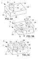
- FIG. 3A, 3B and 3C there is represented a tooling for manufacturing conical washers.
- conical washers are advantageous for its use in aircraft structures when there is a need for softening vibrations in and in repetitive non conformities (undue countersunk) on the skin of some parts of the aircraft structure.
- Conical washers present the drawback that its manufacturing time is long in the state of the art. In an example, the manufacturing time to make a conical washer using a tooling according to the invention is 0,5 hours, and it may be performed in-house.
- the tooling also presents, shown in figure 3B , an upper part (3) comprising a cover (16) on the way to be positioned and fixed with fixing pins (34, 35) on the lower part (1).
- the tooling is shown with lower part (1) and upper part (3) positioned and fixed.
- the drilling machine guiding piece (15) which overflows on the cover (16) in this particular case.
- Said protruding part in the drilling machine guiding piece (15) presents the advantage of presenting the borders from which it can be picked up for easy handling.
- the fixing pin (31) may be a screwing bolt which may allow positioning of the rivet supporting piece (8) in the tooling.
- a manufacturing method making use of the tooling shown in figures 3A, 3B and 3C may follow the steps:
- Figure 4 represents an embodiment of a tooling according to the invention.
- the figure 4 shows a perforating tool, in particular a drilling machine.
- the tooling according to the invention presents the advantage of being easily handled.
- the drilling bit is inserted coaxially to the rivet shat inside the tooling and perpendicular to the plane of the union between lower and upper parts (1, 3).
Landscapes
- Engineering & Computer Science (AREA)
- Mechanical Engineering (AREA)
- Insertion Pins And Rivets (AREA)
Abstract
- a lower part (1) comprising a housing (2),
- an upper part (3) comprising a supporting surface adapted to be positioned and fixed on the first surface of the lower part, said upper part (3) comprising
- a seat (4) on the supporting surface of the upper part (3) adapted to press a rivet head,
- a passageway (6) passing through the upper part (3) providing an open access to the seat (4) of the supporting surface configured as guiding means for a perforating tool,
wherein the lower part (1) and the upper part (3) are adapted for being positioned and fixed in such a way that the axis of the housing (2) coincides with the axis of the passageway (6) of the upper part (3).
Description
- The present invention relates to the field of manufacturing washers. Particularly, there is described a solution for a tooling for the manufacture of washers, a method for the manufacturing of a washer, and the use of a rivet for manufacturing a washer.
- In the field of manufacturing of washers there are known several methods. Depending on the type of washers to be obtained, in the case of plain washers a metallic plate may be used for being perforated with an appropriate die which allows making appropriate holes into the metallic plate for obtaining respective washers. A possible drawback which is present in this kind of manufacturing methods is that an appropriate metallic plate may not be accessible at any time in a small workshop.
- Other methods for manufacturing washers, such as the one described in the patent document
US3902209A , comprising the use of a strip of coil stock material which is cut from a stock and wound on a shaft; however this method is suitable only for fabricating washer of a predetermined diameter and not for obtaining small washers for being used for joining parts of an aircraft, for example. - Besides, depending on the shape of the washer to obtain, there are methods which employ specific tooling; for example, in the patent document
KR101090599B - A problem encountered with the existing tooling for manufacturing washers is that they are very specific and do not allow the local manufacture in a small mechanical workshop, such as the ones in the surroundings of a hangar.
- There is a need, therefore, to have a tooling for the manufacture of washers which is easy to maintain and handle and also which allows obtaining washers from an accessible raw material.
- The present invention provides a solution for the aforementioned problems by a tooling adapted to manufacture a washer according to
claim 1, a method for manufacturing a washer according toclaim 8 and a use according to claim 12. The dependent claims define preferred embodiments of the invention. All the features described in this specification (including the claims, description and drawings) and/or all the steps of the described method can be combined in any combination, with the exception of combinations of such mutually exclusive features and/or steps. - In particular in a first aspect of the invention there is defined a tooling adapted to manufacture a washer comprising
- a lower part comprising a housing on a first surface, extended along an axis, said housing adapted to house a rivet shaft,
- an upper part comprising a supporting surface adapted to be positioned and fixed with the first surface of the lower part, said upper part comprising
- a seat on the supporting surface of the upper part adapted to press a rivet head,
- a passageway, extended along the axis, passing through the upper part providing an open access to the seat of the supporting surface configured as
- guiding means for a perforating tool,
- The housing in the tooling is adapted to house a rivet shaft, wherein a rivet shaft may be of any type tubular or solid, and which presents a cylindrical shape, presenting a longitudinal or rotational axis therein. The housing extends along said rotational axis and is configured such that said axis coincides with the longitudinal or rotational axis of a possible rivet shaft which may be inserted in the housing.
- The passageway in the tooling is adapted to guide a perforating tool wherein a perforating tool presents a cylindrical shape, presenting its rotational axis therein. The passageway is therefore configured such that its rotational axis coincides with the rotational axis of a possible rivet shaft which may be inserted in the housing, when the upper and lower parts are positioned and fixed.
- By lower and upper parts positioned and fixed, in the present description, it must be understood as the lower part in the correct location with respect to the upper part so that the previously-mentioned axes coincide in an unmovably position.
- A seat can be understood as an area where at least part of rivet head may be put under pressure when the lower and upper parts are positioned and fixed.
- In a particular embodiment of a tooling according to the first aspect of the invention the lower part is formed by two pieces, rivet supporting piece and base such that a detachable rivet supporting piece comprises the housing and the base is adapted to receive the rivet supporting piece in a first space.
- This embodiment presents the advantage of having a set of detachable rivet supporting pieces wherein the diameter and length of the housing is adapted to different types of rivets.
- In a particular embodiment of a tooling according to the first aspect of the invention the upper part is formed by two pieces, drilling machine guiding piece and cover such that a detachable drilling machine guiding piece comprises the passageway and the cover is adapted to receive the drilling machine guiding piece in a second space.
- This embodiment presents the advantage of having a set of detachable drilling machine guiding pieces wherein the diameter of the passageway is adapted to different types of rivets. In this case, the perforating tool may also be adapted to perforate according to a predetermined rivet shaft diameter.
- In a particular embodiment of a tooling according to the first aspect of the invention the seat is located in an open cavity.
- A seat in the upper part may be the surface on which a rivet head may be positioned and, according to this embodiment, may also be in an open cavity or groove or edge, in such a way that at least a part of a rivet head is pressed.
- In a particular embodiment of a tooling according to the first aspect of the invention the tooling further comprises a notch at an edge between a surface of the lower part and the space for facilitating the extraction of the rivet supporting piece from the lower part.
- In a particular embodiment of a tooling according to the first aspect of the invention where the lower part is formed by two pieces, the notch is slot-shaped, or channel-shaped such that the access for picking or extracting the rivet supporting piece from the space is open to insert the fingers or tongs or tweezers and interchange the rivet supporting piece with a different one or simply to ease the use of the tooling.
- In a particular embodiment of a tooling according to the first aspect of the invention the passageway may be reinforced with a layer of high hardness material, such as tungsten carbide.
- In a second aspect of the invention there is defined a method for manufacturing a conical washer comprising
- providing a rivet, the rivet comprising a rivet shaft and a rivet head,
- providing a tooling according to the first aspect of the invention,
- housing the rivet shaft in the housing,
- positioning and fixing the upper part and the lower part, in a manner such that the assembly formed by the lower part and the upper part is adapted to
- introducing a perforating tool through the passageway perforating the rivet head substantially in its centre obtaining a perforated hole wherein said perforated hole is sized with a diameter equal or greater that the diameter of the rivet shaft; and the perforation length is such that the rivet shaft is separated from the rivet head, obtaining a washer thereof,
- extracting the washer from the tooling.
- One of the main advantages of a method according to the invention is to provide an alternative and accessible procedure for obtaining washers. The raw material with which a washer may be obtained is a rivet, which is present in the most of workshops.
- Besides, the method can be applied by providing any type of rivet, with any type of shaft or head, obtaining thereof different geometries for a washer. The standardization is present in every joining means or removable joining means commonly used in a workshop such that compatibility is ensured if a washer is manufactured with a rivet.
- In a particular embodiment of a method according to the second aspect of the invention, the step of perforating is performed by means of a drilling machine. Again, this type of tool is present in the most of workshops and, according to this invention, it may be used for manufacturing washers rapidly and, what is more, reducing costs with respect to having a specific tooling for the manufacture of washers and with respect to having non-easy-to-access raw material. Having a tooling according to the invention allows, therefore, applying a manufacturing method using accessible tooling which may be present in the most of workshops and which does not require access to specific and big sized machinery.
- In a particular embodiment of a method according to the second aspect of the invention, where it is applied using tooling comprising a lower part with rivet supporting piece and base, a further step is performed before housing the rivet shaft through the housing, this further step being selecting a detachable rivet supporting piece suitable for the diameter of the rivet shaft. This is advantageous since, depending on the type of rivet the manufacturer may be using, it is possible to have versatility with a tooling according to the invention and implementing a method according to the invention.
- In a particular embodiment of a method according to the second aspect of the invention, where it is applied using tooling comprising an upper part with a drilling machine guiding piece and cover, a further step is performed before positioning and fixing the upper part and the lower part, this further step being selecting a detachable drilling machine guiding piece suitable for the diameter of a perforating tool and a rivet shaft. Once more, the versatility obtained with a tooling comprising detachable and interchangeable pieces is optimum, since there may be the necessity of manufacturing washers for different shapes, geometries and sizes. The tooling according to the first aspect allows implementing a method according to the invention in which a selection of the size of the hole performed on the rivet head, which results in a different diameter of an inner hole of the resulting washer.
- There are three features derived from the technical features of the invention:
- the relation between the diameters of the perforating tool according to the passageway,
- the relation between the diameters of the rivet shaft and the housing, and
- the positioning and fixing of the lower and upper parts.
- These three features provide advantages such as the lack of clearance between the housing and rivet shaft and between the passageway and the perforating tool which allows the perforation to be
- perpendicular to a plane defined by the union of lower and upper parts and
- coaxial with the housing and therefore with the rivet shaft
- Therefore, the perforation results in the separation of a rivet head from the rivet shat allowing the perforation to obtain a washer.
- In a third aspect of the invention there is defined a use of a rivet for manufacturing a washer.
- A use according to this aspect of the invention allows using a rivet for manufacturing washers rapidly and, what is more, reducing costs with respect to having non-easy-to-access raw material which does not require access to specific and big sized machinery. In a particular embodiment of a use of a rivet for manufacturing a washer the manufacturing is performed using a tooling according to the first aspect of the invention.
- In a particular embodiment of a use of a rivet for manufacturing a washer the manufacturing is performed using a tooling according to the first aspect of the invention and implementing a method according to the second aspect of the invention.
- These and other characteristics and advantages of the invention will become clearly understood in view of the detailed description of the invention which becomes apparent from preferred embodiments of the invention, given just as an example and not being limited thereto, with reference to the drawings.
- Figure 1
- This figure represents an embodiment of a tooling according to the invention. In the embodiment there are represented a lower part (1), an upper part (3), a housing (2) a seat (4) and a passageway (6) adapted to act as a guide between a supporting surface (5) and a further surface (7).
- Figure 2
- This figure represents an embodiment of a tooling according to the invention. The figure shows the lower and upper part (1, 3) comprising a rivet supporting piece (8), base (9), drilling machine guiding piece (15) and cover (16).
- Figure 3A
- This figure represents an embodiment of a tooling according to the invention.
- Figure 3B
- This figure represents an embodiment of a tooling according to the invention.
- Figure 3C
- This figure represents an embodiment of a tooling according to the invention.
- Figure 4
- This figure represents an embodiment of a tooling according to the invention. The figure shows a perforating tool, in particular a drilling machine.
- Once the object of the invention has been outlined, specific non-limitative embodiments are described hereinafter. The term rivet may be referred to any type of rivet, for example solid or round head rivets, high-strength structural steel rivets, semi-tubular rivets, blind rivets, oscar rivets, drive rivet, flush rivet, friction-lock rivet and the like, as long as they fulfil the requirement of comprising a shaft and a head.
- As a non-limitative example, in
figure 1 there is shown an embodiment of a tooling according to the invention. In the embodiment there are represented a lower part (1), a upper part (3), a housing (2) a seat (4) and a passageway (6) acting as a guide and the passageway (6) is adapted for acting as a guide for a perforating tool, such as a drill bit, in a trajectory from the supporting surface (5) and a further surface (7). - The embodiment in
figure 2 further comprises the lower part (1) and upper part (3) comprising rivet supporting piece (8), base (9), drilling machine guiding piece (15) and cover (16). The seat is arranged on the supporting surface (5) and the passageway (6) is adapted for acting as a guide for a perforating tool, such as a drill bit. As an advantage it allows having interchangeable first and drilling machine guiding pieces for major versatility and adaptability to different types of rivets being used. - As a non-limitative example, in
figures 3A, 3B and 3C there is represented a tooling for manufacturing conical washers. - In particular, conical washers are advantageous for its use in aircraft structures when there is a need for softening vibrations in and in repetitive non conformities (undue countersunk) on the skin of some parts of the aircraft structure. Conical washers present the drawback that its manufacturing time is long in the state of the art. In an example, the manufacturing time to make a conical washer using a tooling according to the invention is 0,5 hours, and it may be performed in-house.
- The tooling in
figures 3A, 3B and 3C comprise a lower part (1) comprising - a rivet supporting piece (8) comprising a housing (2) adapted for receiving a rivet shaft,
- a space (10) adapted to receive the rivet supporting piece (8),
- a channel-shaped notch (18),
- a fixing pin (31),
- housings (32, 33) for respective fixing pins (34, 35).
- The tooling also presents, shown in
figure 3B , an upper part (3) comprising a cover (16) on the way to be positioned and fixed with fixing pins (34, 35) on the lower part (1). - In
figure 3C , the tooling is shown with lower part (1) and upper part (3) positioned and fixed. On the further surface (7) there can be seen the drilling machine guiding piece (15) which overflows on the cover (16) in this particular case. Said protruding part in the drilling machine guiding piece (15) presents the advantage of presenting the borders from which it can be picked up for easy handling. The fixing pin (31) may be a screwing bolt which may allow positioning of the rivet supporting piece (8) in the tooling. - A manufacturing method making use of the tooling shown in
figures 3A, 3B and 3C may follow the steps: - inserting a rivet supporting piece (8) in the space (10) of the lower part (1) part of the tool, specific for the rivet to be used, and fix it with the adjusting screwing bolt (31),
- inserting the rivet inside the housing (2),
- positioning and fix the upper part (3) making use of two fixing pins (34, 35),
- inserting the drilling machine guiding piece (15) in the cover (16) for a drilling machine to be inserted and
- drilling the rivet with a diameter exactly the same as the threaded part in order to have a washer from the head of the rivet
-
Figure 4 represents an embodiment of a tooling according to the invention. Thefigure 4 shows a perforating tool, in particular a drilling machine. As it can be unambiguously derived fromfigure 4 , the tooling according to the invention presents the advantage of being easily handled. As an advantage from the configuration of the tooling of the invention, the drilling bit is inserted coaxially to the rivet shat inside the tooling and perpendicular to the plane of the union between lower and upper parts (1, 3).
Claims (14)
- Tooling adapted to manufacture a washer comprising- a lower part (1) comprising a housing (2) on a first surface, extended along an axis, said housing (2) adapted to house a rivet shaft,- an upper part (3) comprising a supporting surface adapted to be positioned and fixed with the first surface of the lower part, said upper part (3) comprisingwherein the lower part (1) and the upper part (3) are adapted for being positioned and fixed in such a way that the axis of the housing (2) coincides with the axis of the passageway (6) of the upper part (3).- a seat (4) on the supporting surface of the upper part (3) adapted to press a rivet head,- a passageway (6), extended along an axis, passing through the upper part (3) providing an open access to the seat (4) of the supporting surface configured as- guiding means for a perforating tool,
- Tooling according to claim 1 wherein the lower part is formed by two pieces, rivet supporting piece (8) and base (9) such that a detachable rivet supporting piece (8) comprises the housing (2) and the base (9) is adapted to receive the rivet supporting piece (8) in a first space (10).
- Tooling according to claim 1 or 2 wherein the upper part (3) is formed by two pieces, drilling machine guiding piece (15) and cover (16) such that a detachable drilling machine guiding piece (15) comprises the passageway (6) and the cover (16) is adapted to receive the drilling machine guiding piece (15) in a second space (17).
- Tooling according to any of the preceding claims wherein the seat (4) is located in an open cavity.
- Tooling according to any of claims 2 to 4 further comprising a notch (18) at an edge between the first surface of the lower part (1) and the space (10) for facilitating the extraction of the rivet supporting piece (8) from the lower part (1).
- Tooling according to claim 5 wherein the notch (18) is slot-shaped.
- Tooling according to any of the preceding claims characterized in that the passageway (6) is reinforced with a layer of high hardness material, such as tungsten carbide.
- Method for manufacturing a conical washer comprising- providing a rivet (11), the rivet comprising a rivet shaft (12) and a rivet head (13),- providing a tooling according to any of claims 1 to 7,- housing the rivet shaft in the housing (2),- positioning and fixing the upper part (3) and the lower part (1), in a manner such that the assembly formed by the lower part and the upper part is adapted to- introducing a perforating tool through the passageway perforating the rivet head substantially in its centre obtaining a perforated hole wherein said perforated hole is sized with a diameter equal or greater that the diameter of the rivet shaft; and the perforation length is such that the rivet shaft is separated from the rivet head, obtaining a washer thereof,- extracting the washer from the tooling.
- Method according to any of claim 8 wherein the step of perforating is performed by means of a drilling machine.
- Method according to any of claims 8 or 9 wherein the tool comprises a lower part (1) comprising rivet supporting piece (8) and base (9) according to claim 2 and a further step is performed before housing the rivet shaft through the housing (2), this further step being selecting a detachable rivet supporting piece (8) suitable for the diameter of the rivet shaft.
- Method according to any of claims 8 to 10 wherein the tool comprises an upper part (3) comprising a drilling machine guiding piece (15) and cover (16) according to claim 3 and a further step is performed before positioning and fixing the upper part (3) and the lower part (1), this further step being selecting a detachable drilling machine guiding piece (15) suitable for the diameter of a perforating tool and a rivet shaft.
- Use of a rivet for manufacturing a washer.
- Use of a rivet for manufacturing a washer by the use of a tooling according to any of claims 1 to 7.
- Use of a rivet and a tooling according to any of claims 1 to 7 for manufacturing a washer by a method according to any of claims 8 to 11.
Priority Applications (2)
| Application Number | Priority Date | Filing Date | Title |
|---|---|---|---|
| EP14382291.4A EP2979792B1 (en) | 2014-07-29 | 2014-07-29 | Tooling adapted to manufacture a washer, method for manufacturing a conical washer, and use of a rivet for manufacturing a washer |
| ES14382291T ES2900827T3 (en) | 2014-07-29 | 2014-07-29 | Tool adapted for the manufacture of a washer, method for making a conical washer, and use of a rivet for the manufacture of a washer |
Applications Claiming Priority (1)
| Application Number | Priority Date | Filing Date | Title |
|---|---|---|---|
| EP14382291.4A EP2979792B1 (en) | 2014-07-29 | 2014-07-29 | Tooling adapted to manufacture a washer, method for manufacturing a conical washer, and use of a rivet for manufacturing a washer |
Publications (2)
| Publication Number | Publication Date |
|---|---|
| EP2979792A1 true EP2979792A1 (en) | 2016-02-03 |
| EP2979792B1 EP2979792B1 (en) | 2021-11-03 |
Family
ID=51257447
Family Applications (1)
| Application Number | Title | Priority Date | Filing Date |
|---|---|---|---|
| EP14382291.4A Not-in-force EP2979792B1 (en) | 2014-07-29 | 2014-07-29 | Tooling adapted to manufacture a washer, method for manufacturing a conical washer, and use of a rivet for manufacturing a washer |
Country Status (2)
| Country | Link |
|---|---|
| EP (1) | EP2979792B1 (en) |
| ES (1) | ES2900827T3 (en) |
Cited By (1)
| Publication number | Priority date | Publication date | Assignee | Title |
|---|---|---|---|---|
| CN112025347A (en) * | 2020-07-21 | 2020-12-04 | 广东长盈精密技术有限公司 | Rotating shaft processing equipment |
Citations (5)
| Publication number | Priority date | Publication date | Assignee | Title |
|---|---|---|---|---|
| FR916987A (en) * | 1945-07-05 | 1946-12-20 | Drill accessory | |
| US2898785A (en) * | 1958-04-28 | 1959-08-11 | Rohr Aircraft Corp | Drill jig |
| US3902209A (en) | 1967-11-13 | 1975-09-02 | Electrical Fittings Corp | Threaded lock washer and method for fabrication thereof |
| US5758996A (en) * | 1996-09-09 | 1998-06-02 | Loudon; Gary J. | Drill centering device |
| KR101090599B1 (en) | 2011-04-19 | 2011-12-08 | 홍성표 | Spring washer manufacturing mold and spring washer manufacturing method using the same |
-
2014
- 2014-07-29 EP EP14382291.4A patent/EP2979792B1/en not_active Not-in-force
- 2014-07-29 ES ES14382291T patent/ES2900827T3/en active Active
Patent Citations (5)
| Publication number | Priority date | Publication date | Assignee | Title |
|---|---|---|---|---|
| FR916987A (en) * | 1945-07-05 | 1946-12-20 | Drill accessory | |
| US2898785A (en) * | 1958-04-28 | 1959-08-11 | Rohr Aircraft Corp | Drill jig |
| US3902209A (en) | 1967-11-13 | 1975-09-02 | Electrical Fittings Corp | Threaded lock washer and method for fabrication thereof |
| US5758996A (en) * | 1996-09-09 | 1998-06-02 | Loudon; Gary J. | Drill centering device |
| KR101090599B1 (en) | 2011-04-19 | 2011-12-08 | 홍성표 | Spring washer manufacturing mold and spring washer manufacturing method using the same |
Cited By (2)
| Publication number | Priority date | Publication date | Assignee | Title |
|---|---|---|---|---|
| CN112025347A (en) * | 2020-07-21 | 2020-12-04 | 广东长盈精密技术有限公司 | Rotating shaft processing equipment |
| CN112025347B (en) * | 2020-07-21 | 2022-02-18 | 广东长盈精密技术有限公司 | Rotary shaft processing equipment |
Also Published As
| Publication number | Publication date |
|---|---|
| ES2900827T3 (en) | 2022-03-18 |
| EP2979792B1 (en) | 2021-11-03 |
Similar Documents
| Publication | Publication Date | Title |
|---|---|---|
| KR101532246B1 (en) | Rivet nut unit | |
| EP1623126B1 (en) | Blind fastener and method of removing it from a workpiece | |
| US20130145916A1 (en) | Sleeve for a punch assembly | |
| US20140047894A1 (en) | Low profile pilot assembly and method for metal forming dies | |
| US2373901A (en) | Boss forming process | |
| JP4990756B2 (en) | Drilling device for through hole in work peripheral wall | |
| EP2979792B1 (en) | Tooling adapted to manufacture a washer, method for manufacturing a conical washer, and use of a rivet for manufacturing a washer | |
| KR20120129657A (en) | Punching apparatus for pipe | |
| JP2005103624A (en) | Punch for press die, and guide structure and chamfering method in stripper plate of punch for press die | |
| US10228053B2 (en) | Method of reducing required machining on a pin type carrier | |
| EP3287210A2 (en) | Self-piercing rivet, arrangement with a self-piercing rivet and method for forming a joint | |
| JP2008119703A (en) | Punching device and its punching method | |
| JP2005262263A (en) | Punching device | |
| JP2003251420A (en) | Knockout punch with pilot hole locator | |
| US2920509A (en) | Drill bushing and jig | |
| US20100313725A1 (en) | Puncher | |
| JP5645527B2 (en) | Punch die and screw hole machining method using the punch die | |
| US20060093448A1 (en) | Drills | |
| EP3037218A1 (en) | Tool and method for treating a workpiece with a tool element of a tool | |
| US20170087736A1 (en) | Hydraulic Punch Machine, and Punch Carrier for a Punch Machine | |
| EP3130421A1 (en) | Bottom cutting step up reamer | |
| DE102015108902B3 (en) | reamer | |
| CA2842240A1 (en) | Shoulder pilot assembly with self-contained stripper and method for metal forming dies | |
| JP2005161452A (en) | Plate material drilling method and plate material drilling tool | |
| USH419H (en) | Contoured punch tool for removing semi-tubular rivets |
Legal Events
| Date | Code | Title | Description |
|---|---|---|---|
| PUAI | Public reference made under article 153(3) epc to a published international application that has entered the european phase |
Free format text: ORIGINAL CODE: 0009012 |
|
| AK | Designated contracting states |
Kind code of ref document: A1 Designated state(s): AL AT BE BG CH CY CZ DE DK EE ES FI FR GB GR HR HU IE IS IT LI LT LU LV MC MK MT NL NO PL PT RO RS SE SI SK SM TR |
|
| AX | Request for extension of the european patent |
Extension state: BA ME |
|
| 17P | Request for examination filed |
Effective date: 20160802 |
|
| RBV | Designated contracting states (corrected) |
Designated state(s): AL AT BE BG CH CY CZ DE DK EE ES FI FR GB GR HR HU IE IS IT LI LT LU LV MC MK MT NL NO PL PT RO RS SE SI SK SM TR |
|
| RIC1 | Information provided on ipc code assigned before grant |
Ipc: B21J 15/00 20060101ALI20210325BHEP Ipc: B21J 15/50 20060101ALI20210325BHEP Ipc: B23B 47/28 20060101AFI20210325BHEP |
|
| GRAP | Despatch of communication of intention to grant a patent |
Free format text: ORIGINAL CODE: EPIDOSNIGR1 |
|
| STAA | Information on the status of an ep patent application or granted ep patent |
Free format text: STATUS: GRANT OF PATENT IS INTENDED |
|
| INTG | Intention to grant announced |
Effective date: 20210604 |
|
| GRAS | Grant fee paid |
Free format text: ORIGINAL CODE: EPIDOSNIGR3 |
|
| GRAA | (expected) grant |
Free format text: ORIGINAL CODE: 0009210 |
|
| STAA | Information on the status of an ep patent application or granted ep patent |
Free format text: STATUS: THE PATENT HAS BEEN GRANTED |
|
| AK | Designated contracting states |
Kind code of ref document: B1 Designated state(s): AL AT BE BG CH CY CZ DE DK EE ES FI FR GB GR HR HU IE IS IT LI LT LU LV MC MK MT NL NO PL PT RO RS SE SI SK SM TR |
|
| REG | Reference to a national code |
Ref country code: GB Ref legal event code: FG4D |
|
| REG | Reference to a national code |
Ref country code: AT Ref legal event code: REF Ref document number: 1443522 Country of ref document: AT Kind code of ref document: T Effective date: 20211115 Ref country code: CH Ref legal event code: EP |
|
| REG | Reference to a national code |
Ref country code: DE Ref legal event code: R096 Ref document number: 602014081003 Country of ref document: DE |
|
| REG | Reference to a national code |
Ref country code: IE Ref legal event code: FG4D |
|
| REG | Reference to a national code |
Ref country code: LT Ref legal event code: MG9D |
|
| REG | Reference to a national code |
Ref country code: NL Ref legal event code: MP Effective date: 20211103 |
|
| REG | Reference to a national code |
Ref country code: AT Ref legal event code: MK05 Ref document number: 1443522 Country of ref document: AT Kind code of ref document: T Effective date: 20211103 |
|
| REG | Reference to a national code |
Ref country code: ES Ref legal event code: FG2A Ref document number: 2900827 Country of ref document: ES Kind code of ref document: T3 Effective date: 20220318 |
|
| PG25 | Lapsed in a contracting state [announced via postgrant information from national office to epo] |
Ref country code: RS Free format text: LAPSE BECAUSE OF FAILURE TO SUBMIT A TRANSLATION OF THE DESCRIPTION OR TO PAY THE FEE WITHIN THE PRESCRIBED TIME-LIMIT Effective date: 20211103 Ref country code: LT Free format text: LAPSE BECAUSE OF FAILURE TO SUBMIT A TRANSLATION OF THE DESCRIPTION OR TO PAY THE FEE WITHIN THE PRESCRIBED TIME-LIMIT Effective date: 20211103 Ref country code: FI Free format text: LAPSE BECAUSE OF FAILURE TO SUBMIT A TRANSLATION OF THE DESCRIPTION OR TO PAY THE FEE WITHIN THE PRESCRIBED TIME-LIMIT Effective date: 20211103 Ref country code: BG Free format text: LAPSE BECAUSE OF FAILURE TO SUBMIT A TRANSLATION OF THE DESCRIPTION OR TO PAY THE FEE WITHIN THE PRESCRIBED TIME-LIMIT Effective date: 20220203 Ref country code: AT Free format text: LAPSE BECAUSE OF FAILURE TO SUBMIT A TRANSLATION OF THE DESCRIPTION OR TO PAY THE FEE WITHIN THE PRESCRIBED TIME-LIMIT Effective date: 20211103 |
|
| PG25 | Lapsed in a contracting state [announced via postgrant information from national office to epo] |
Ref country code: IS Free format text: LAPSE BECAUSE OF FAILURE TO SUBMIT A TRANSLATION OF THE DESCRIPTION OR TO PAY THE FEE WITHIN THE PRESCRIBED TIME-LIMIT Effective date: 20220303 Ref country code: SE Free format text: LAPSE BECAUSE OF FAILURE TO SUBMIT A TRANSLATION OF THE DESCRIPTION OR TO PAY THE FEE WITHIN THE PRESCRIBED TIME-LIMIT Effective date: 20211103 Ref country code: PT Free format text: LAPSE BECAUSE OF FAILURE TO SUBMIT A TRANSLATION OF THE DESCRIPTION OR TO PAY THE FEE WITHIN THE PRESCRIBED TIME-LIMIT Effective date: 20220303 Ref country code: PL Free format text: LAPSE BECAUSE OF FAILURE TO SUBMIT A TRANSLATION OF THE DESCRIPTION OR TO PAY THE FEE WITHIN THE PRESCRIBED TIME-LIMIT Effective date: 20211103 Ref country code: NO Free format text: LAPSE BECAUSE OF FAILURE TO SUBMIT A TRANSLATION OF THE DESCRIPTION OR TO PAY THE FEE WITHIN THE PRESCRIBED TIME-LIMIT Effective date: 20220203 Ref country code: NL Free format text: LAPSE BECAUSE OF FAILURE TO SUBMIT A TRANSLATION OF THE DESCRIPTION OR TO PAY THE FEE WITHIN THE PRESCRIBED TIME-LIMIT Effective date: 20211103 Ref country code: LV Free format text: LAPSE BECAUSE OF FAILURE TO SUBMIT A TRANSLATION OF THE DESCRIPTION OR TO PAY THE FEE WITHIN THE PRESCRIBED TIME-LIMIT Effective date: 20211103 Ref country code: HR Free format text: LAPSE BECAUSE OF FAILURE TO SUBMIT A TRANSLATION OF THE DESCRIPTION OR TO PAY THE FEE WITHIN THE PRESCRIBED TIME-LIMIT Effective date: 20211103 Ref country code: GR Free format text: LAPSE BECAUSE OF FAILURE TO SUBMIT A TRANSLATION OF THE DESCRIPTION OR TO PAY THE FEE WITHIN THE PRESCRIBED TIME-LIMIT Effective date: 20220204 |
|
| PG25 | Lapsed in a contracting state [announced via postgrant information from national office to epo] |
Ref country code: SM Free format text: LAPSE BECAUSE OF FAILURE TO SUBMIT A TRANSLATION OF THE DESCRIPTION OR TO PAY THE FEE WITHIN THE PRESCRIBED TIME-LIMIT Effective date: 20211103 Ref country code: SK Free format text: LAPSE BECAUSE OF FAILURE TO SUBMIT A TRANSLATION OF THE DESCRIPTION OR TO PAY THE FEE WITHIN THE PRESCRIBED TIME-LIMIT Effective date: 20211103 Ref country code: RO Free format text: LAPSE BECAUSE OF FAILURE TO SUBMIT A TRANSLATION OF THE DESCRIPTION OR TO PAY THE FEE WITHIN THE PRESCRIBED TIME-LIMIT Effective date: 20211103 Ref country code: EE Free format text: LAPSE BECAUSE OF FAILURE TO SUBMIT A TRANSLATION OF THE DESCRIPTION OR TO PAY THE FEE WITHIN THE PRESCRIBED TIME-LIMIT Effective date: 20211103 Ref country code: DK Free format text: LAPSE BECAUSE OF FAILURE TO SUBMIT A TRANSLATION OF THE DESCRIPTION OR TO PAY THE FEE WITHIN THE PRESCRIBED TIME-LIMIT Effective date: 20211103 Ref country code: CZ Free format text: LAPSE BECAUSE OF FAILURE TO SUBMIT A TRANSLATION OF THE DESCRIPTION OR TO PAY THE FEE WITHIN THE PRESCRIBED TIME-LIMIT Effective date: 20211103 |
|
| REG | Reference to a national code |
Ref country code: DE Ref legal event code: R097 Ref document number: 602014081003 Country of ref document: DE |
|
| PLBE | No opposition filed within time limit |
Free format text: ORIGINAL CODE: 0009261 |
|
| STAA | Information on the status of an ep patent application or granted ep patent |
Free format text: STATUS: NO OPPOSITION FILED WITHIN TIME LIMIT |
|
| 26N | No opposition filed |
Effective date: 20220804 |
|
| PG25 | Lapsed in a contracting state [announced via postgrant information from national office to epo] |
Ref country code: AL Free format text: LAPSE BECAUSE OF FAILURE TO SUBMIT A TRANSLATION OF THE DESCRIPTION OR TO PAY THE FEE WITHIN THE PRESCRIBED TIME-LIMIT Effective date: 20211103 |
|
| PGFP | Annual fee paid to national office [announced via postgrant information from national office to epo] |
Ref country code: GB Payment date: 20220721 Year of fee payment: 9 Ref country code: ES Payment date: 20220921 Year of fee payment: 9 Ref country code: DE Payment date: 20220720 Year of fee payment: 9 |
|
| PG25 | Lapsed in a contracting state [announced via postgrant information from national office to epo] |
Ref country code: SI Free format text: LAPSE BECAUSE OF FAILURE TO SUBMIT A TRANSLATION OF THE DESCRIPTION OR TO PAY THE FEE WITHIN THE PRESCRIBED TIME-LIMIT Effective date: 20211103 |
|
| PGFP | Annual fee paid to national office [announced via postgrant information from national office to epo] |
Ref country code: FR Payment date: 20220720 Year of fee payment: 9 |
|
| PG25 | Lapsed in a contracting state [announced via postgrant information from national office to epo] |
Ref country code: MC Free format text: LAPSE BECAUSE OF FAILURE TO SUBMIT A TRANSLATION OF THE DESCRIPTION OR TO PAY THE FEE WITHIN THE PRESCRIBED TIME-LIMIT Effective date: 20211103 |
|
| REG | Reference to a national code |
Ref country code: CH Ref legal event code: PL |
|
| REG | Reference to a national code |
Ref country code: BE Ref legal event code: MM Effective date: 20220731 |
|
| PG25 | Lapsed in a contracting state [announced via postgrant information from national office to epo] |
Ref country code: LU Free format text: LAPSE BECAUSE OF NON-PAYMENT OF DUE FEES Effective date: 20220729 Ref country code: LI Free format text: LAPSE BECAUSE OF NON-PAYMENT OF DUE FEES Effective date: 20220731 Ref country code: CH Free format text: LAPSE BECAUSE OF NON-PAYMENT OF DUE FEES Effective date: 20220731 |
|
| PG25 | Lapsed in a contracting state [announced via postgrant information from national office to epo] |
Ref country code: IT Free format text: LAPSE BECAUSE OF FAILURE TO SUBMIT A TRANSLATION OF THE DESCRIPTION OR TO PAY THE FEE WITHIN THE PRESCRIBED TIME-LIMIT Effective date: 20211103 Ref country code: BE Free format text: LAPSE BECAUSE OF NON-PAYMENT OF DUE FEES Effective date: 20220731 |
|
| PG25 | Lapsed in a contracting state [announced via postgrant information from national office to epo] |
Ref country code: IE Free format text: LAPSE BECAUSE OF NON-PAYMENT OF DUE FEES Effective date: 20220729 |
|
| REG | Reference to a national code |
Ref country code: DE Ref legal event code: R119 Ref document number: 602014081003 Country of ref document: DE |
|
| GBPC | Gb: european patent ceased through non-payment of renewal fee |
Effective date: 20230729 |
|
| PG25 | Lapsed in a contracting state [announced via postgrant information from national office to epo] |
Ref country code: HU Free format text: LAPSE BECAUSE OF FAILURE TO SUBMIT A TRANSLATION OF THE DESCRIPTION OR TO PAY THE FEE WITHIN THE PRESCRIBED TIME-LIMIT; INVALID AB INITIO Effective date: 20140729 |
|
| PG25 | Lapsed in a contracting state [announced via postgrant information from national office to epo] |
Ref country code: MK Free format text: LAPSE BECAUSE OF FAILURE TO SUBMIT A TRANSLATION OF THE DESCRIPTION OR TO PAY THE FEE WITHIN THE PRESCRIBED TIME-LIMIT Effective date: 20211103 Ref country code: DE Free format text: LAPSE BECAUSE OF NON-PAYMENT OF DUE FEES Effective date: 20240201 Ref country code: CY Free format text: LAPSE BECAUSE OF FAILURE TO SUBMIT A TRANSLATION OF THE DESCRIPTION OR TO PAY THE FEE WITHIN THE PRESCRIBED TIME-LIMIT Effective date: 20211103 Ref country code: GB Free format text: LAPSE BECAUSE OF NON-PAYMENT OF DUE FEES Effective date: 20230729 |
|
| PG25 | Lapsed in a contracting state [announced via postgrant information from national office to epo] |
Ref country code: FR Free format text: LAPSE BECAUSE OF NON-PAYMENT OF DUE FEES Effective date: 20230731 |
|
| PG25 | Lapsed in a contracting state [announced via postgrant information from national office to epo] |
Ref country code: TR Free format text: LAPSE BECAUSE OF FAILURE TO SUBMIT A TRANSLATION OF THE DESCRIPTION OR TO PAY THE FEE WITHIN THE PRESCRIBED TIME-LIMIT Effective date: 20211103 |
|
| REG | Reference to a national code |
Ref country code: ES Ref legal event code: FD2A Effective date: 20240902 |
|
| PG25 | Lapsed in a contracting state [announced via postgrant information from national office to epo] |
Ref country code: MT Free format text: LAPSE BECAUSE OF FAILURE TO SUBMIT A TRANSLATION OF THE DESCRIPTION OR TO PAY THE FEE WITHIN THE PRESCRIBED TIME-LIMIT Effective date: 20211103 |
|
| PG25 | Lapsed in a contracting state [announced via postgrant information from national office to epo] |
Ref country code: ES Free format text: LAPSE BECAUSE OF NON-PAYMENT OF DUE FEES Effective date: 20230730 |
|
| PG25 | Lapsed in a contracting state [announced via postgrant information from national office to epo] |
Ref country code: ES Free format text: LAPSE BECAUSE OF NON-PAYMENT OF DUE FEES Effective date: 20230730 |