EP2979773A1 - Gelenkgehäuse für eine Spurstange und Verfahren zu seiner Herstellung - Google Patents
Gelenkgehäuse für eine Spurstange und Verfahren zu seiner Herstellung Download PDFInfo
- Publication number
- EP2979773A1 EP2979773A1 EP14179161.6A EP14179161A EP2979773A1 EP 2979773 A1 EP2979773 A1 EP 2979773A1 EP 14179161 A EP14179161 A EP 14179161A EP 2979773 A1 EP2979773 A1 EP 2979773A1
- Authority
- EP
- European Patent Office
- Prior art keywords
- housing
- transition region
- shaft housing
- ball
- joint
- Prior art date
- Legal status (The legal status is an assumption and is not a legal conclusion. Google has not performed a legal analysis and makes no representation as to the accuracy of the status listed.)
- Granted
Links
Images


Classifications
-
- B—PERFORMING OPERATIONS; TRANSPORTING
- B21—MECHANICAL METAL-WORKING WITHOUT ESSENTIALLY REMOVING MATERIAL; PUNCHING METAL
- B21K—MAKING FORGED OR PRESSED METAL PRODUCTS, e.g. HORSE-SHOES, RIVETS, BOLTS OR WHEELS
- B21K1/00—Making machine elements
- B21K1/26—Making machine elements housings or supporting parts, e.g. axle housings, engine mountings
-
- B—PERFORMING OPERATIONS; TRANSPORTING
- B21—MECHANICAL METAL-WORKING WITHOUT ESSENTIALLY REMOVING MATERIAL; PUNCHING METAL
- B21K—MAKING FORGED OR PRESSED METAL PRODUCTS, e.g. HORSE-SHOES, RIVETS, BOLTS OR WHEELS
- B21K1/00—Making machine elements
- B21K1/76—Making machine elements elements not mentioned in one of the preceding groups
- B21K1/762—Coupling members for conveying mechanical motion, e.g. universal joints
-
- F—MECHANICAL ENGINEERING; LIGHTING; HEATING; WEAPONS; BLASTING
- F16—ENGINEERING ELEMENTS AND UNITS; GENERAL MEASURES FOR PRODUCING AND MAINTAINING EFFECTIVE FUNCTIONING OF MACHINES OR INSTALLATIONS; THERMAL INSULATION IN GENERAL
- F16C—SHAFTS; FLEXIBLE SHAFTS; ELEMENTS OR CRANKSHAFT MECHANISMS; ROTARY BODIES OTHER THAN GEARING ELEMENTS; BEARINGS
- F16C11/00—Pivots; Pivotal connections
- F16C11/04—Pivotal connections
- F16C11/06—Ball-joints; Other joints having more than one degree of angular freedom, i.e. universal joints
- F16C11/0619—Ball-joints; Other joints having more than one degree of angular freedom, i.e. universal joints the female part comprising a blind socket receiving the male part
- F16C11/0623—Construction or details of the socket member
-
- F—MECHANICAL ENGINEERING; LIGHTING; HEATING; WEAPONS; BLASTING
- F16—ENGINEERING ELEMENTS AND UNITS; GENERAL MEASURES FOR PRODUCING AND MAINTAINING EFFECTIVE FUNCTIONING OF MACHINES OR INSTALLATIONS; THERMAL INSULATION IN GENERAL
- F16C—SHAFTS; FLEXIBLE SHAFTS; ELEMENTS OR CRANKSHAFT MECHANISMS; ROTARY BODIES OTHER THAN GEARING ELEMENTS; BEARINGS
- F16C11/00—Pivots; Pivotal connections
- F16C11/04—Pivotal connections
- F16C11/06—Ball-joints; Other joints having more than one degree of angular freedom, i.e. universal joints
- F16C11/0685—Manufacture of ball-joints and parts thereof, e.g. assembly of ball-joints
-
- F—MECHANICAL ENGINEERING; LIGHTING; HEATING; WEAPONS; BLASTING
- F16—ENGINEERING ELEMENTS AND UNITS; GENERAL MEASURES FOR PRODUCING AND MAINTAINING EFFECTIVE FUNCTIONING OF MACHINES OR INSTALLATIONS; THERMAL INSULATION IN GENERAL
- F16C—SHAFTS; FLEXIBLE SHAFTS; ELEMENTS OR CRANKSHAFT MECHANISMS; ROTARY BODIES OTHER THAN GEARING ELEMENTS; BEARINGS
- F16C11/00—Pivots; Pivotal connections
- F16C11/04—Pivotal connections
- F16C11/06—Ball-joints; Other joints having more than one degree of angular freedom, i.e. universal joints
- F16C11/0695—Mounting of ball-joints, e.g. fixing them to a connecting rod
-
- F—MECHANICAL ENGINEERING; LIGHTING; HEATING; WEAPONS; BLASTING
- F16—ENGINEERING ELEMENTS AND UNITS; GENERAL MEASURES FOR PRODUCING AND MAINTAINING EFFECTIVE FUNCTIONING OF MACHINES OR INSTALLATIONS; THERMAL INSULATION IN GENERAL
- F16C—SHAFTS; FLEXIBLE SHAFTS; ELEMENTS OR CRANKSHAFT MECHANISMS; ROTARY BODIES OTHER THAN GEARING ELEMENTS; BEARINGS
- F16C2226/00—Joining parts; Fastening; Assembling or mounting parts
- F16C2226/50—Positive connections
- F16C2226/60—Positive connections with threaded parts, e.g. bolt and nut connections
Definitions
- the invention relates to a joint housing for a tie rod, with a shaft housing for connection to an axial pin and a ball housing for receiving a ball joint.
- the invention relates to a method for producing a joint housing for a tie rod, wherein a blank is provided, wherein from a region of the blank, a shaft housing for connection to an axial pin and from another region of the blank is formed a ball housing for receiving a ball joint
- Such joint housing are well known from the prior art, for example from the DE 10 2008 053 796 A1 , Such a joint housing serves to connect the axial pin of a tie rod articulated to a wheel carrier of a vehicle.
- the shaft housing serves to receive the axial pin.
- the axial pin can be screwed, for example, in a bore with internal thread of the shaft housing.
- the ball housing is used for connection with the wheel carrier.
- the ball housing provides a spherical receptacle in which a connectable to the wheel carrier ball can be movably mounted. This arrangement allows rotations between the wheel carrier and the axial pin about all three spatial directions.
- the shaft housing and the ball housing merge into each other through a transition region.
- the transition region thus connects the shaft housing with the ball housing.
- the shaft housing must by design have a minimum diameter, which results in dependence of the shaft housing provided in the bore with internal thread for receiving the axial pin.
- completely different geometric or mechanical requirements may exist on the ball housing.
- the "flat-pressed" transition region known from the prior art is characterized in that it is reduced with respect to a first spatial direction relative to the diameter of the shaft housing, with respect to a second spatial direction, however, is just as wide or even wider than the shaft housing , This is clear in the two figures of DE 10 2008 053 796 A1 shown.
- the cross section of the transition region is thus no longer only tapered in certain spatial directions, as is known from the prior art, but rather over the entire cross section.
- the transition area is in each Radial direction spaced from the outer surface of the shaft housing.
- the shaft housing passes through a kind of full-scale shaft paragraph in the transition area.
- the diameter of the transition region is reduced relative to the diameter of the shaft housing.
- the cross-sectional contour of the transition region and / or the shaft housing may be circular.
- the transition region is not processed by machining or forging, but by cold forming.
- Cold forming refers to the forming of metals at a temperature well below the recrystallization temperature.
- the advantage of cold forming is that either no further post-processing or only minor rework is required. By cold forming already very small dimensional tolerances can be achieved.
- the transition region can thus be formed by cold forming "(near) net shape".
- the strength of the cold-worked material increases by strain hardening.
- the joint housing according to the invention has a transition region, which is tapered over the entire cross section, in particular with respect to the shaft housing.
- This has the advantage that the ball housing can be bent particularly easily in three dimensions relative to the shaft housing. Such a three-dimensional bend may be required depending on the purpose of the tie rod.
- the transition region tapered over the entire cross section it is possible to ensure that the bending stiffness of the transitional region is the same in both spatial directions at right angles to the longitudinal axis of the shaft housing.
- greater design freedom in the construction of the joint housing compared to the known from the prior art joint housing greater design freedom in the construction of the joint housing. It is also such bends between the shaft housing on the one hand and ball housing on the other hand can be achieved, which were not possible in the known from the prior art solutions.
- transition area after the bending process may not have to be reworked because the desired geometry and the desired
- the cross-sectional contours of the shaft housing and the transition region are of identical design, but the cross-sectional contours of the transition region are designed to be scaled down to a smaller size.
- the two cross-sectional contours are qualitatively equally shaped.
- the cross-sectional contour of the transition region is scaled smaller in relation to the cross-sectional contour of the shaft housing.
- a connecting portion between the outer surface of the shaft housing and the outer surface of the transition portion is formed the same over the entire circumference. This simplifies the further processing of the joint housing, which also structurally very complex designs are made possible.
- the transition region and the shaft housing extend at least partially coaxially.
- their longitudinal axes could also be eccentric.
- the transition region and the shaft housing may extend at least partially in parallel directions.
- the transition region and / or the shaft housing can be rotationally symmetrical.
- the transition region may be curved with respect to its longitudinal axis.
- the curvature may be formed around or combined around two axes. These axes are radial to the longitudinal axis and are linearly independent. This means that both the ball housing and the shaft housing can extend straight. An angular arrangement to each other is achieved by the curved transition region.
- the transition region can be curved in a particularly simple manner, since it is tapered over the entire cross section relative to the shaft housing and / or the ball housing. Curved in the sense of the invention comprises a curved course, a kink, that is pointed course and / or the like.
- the solution proposes that a transition region between the region for the shaft housing and the region for the ball housing be tapered over the entire cross section on the blank.
- this transition region is not only partially, but rejuvenated over the entire cross-section. This means that there is a rejuvenation over the entire circumference of the transition area.
- the transition region can be tapered rotationally symmetrical.
- the transition region can be tapered before the shaft housing and the ball housing are formed. However, it can also be formed only subsequently or together with the shaft housing and / or the ball housing. Preferably, the transition region is tapered by cold forming. This has already been explained above.
- a joint housing produced by the method according to the invention has the advantage that bending between the shaft housing and the ball housing is simpler and more flexible in terms of design freedom.
- the taper over the entire cross-section leads to a significant weight reduction, so that a joint housing produced by the method according to the invention can be referred to as a lightweight joint housing.
- FIG. 1 shows a joint housing 1 according to the prior art.
- This has a shaft housing 2 and a ball housing 3.
- the shaft housing 2 and the ball housing 3 are interconnected by a transition region 4.
- a threaded bore 5 is provided, which has a threaded portion 9 as an internal thread.
- the internal thread has a thread core diameter 7.
- the shaft housing 2 is circular in cross section. At the circular cross-section, an end provided key surface 6 connects. This is designed as an external hexagon.
- a threaded bore 5 a provided with a corresponding external thread axial pin can be screwed.
- the ball housing 3 points in FIG. 1 a through hole 8.
- the ball housing 3 could also be executed closed on one side.
- a ball can be received.
- the ball can be arranged on a wheel carrier of a vehicle.
- transition region 4 is indeed tapered in the direction of the longitudinal axis of the through hole 8 with respect to the shaft housing 2 and the ball housing 3.
- the transition region 4 is significantly widened in a direction radial to the through hole at least with respect to the shaft housing 2. This design of the transition region 4 according to the prior art may be referred to as flattened.
- FIG. 3 shows, however, an embodiment of a joint housing according to the invention 11.
- This has a shaft housing 12 and a ball housing 13.
- the shaft housing 12 and the ball housing 13 are interconnected by a transition region 14 connected.
- the entire joint housing 11 may be integrally formed, in particular from a cast.
- the shaft housing 12 has a circular cross-sectional contour. Only at one end opposite the ball housing 13 a key surface 16 is provided. This is designed as an external hexagon. At this end facing away from the ball housing 13 also has a threaded bore 15 is inserted into the shaft housing 12. The threaded bore is formed centrally in the shaft housing 12. It has an internal thread.
- the transition region 14 is tapered with respect to the shaft housing 12.
- the transition region 14 is tapered with respect to the entire cross section.
- the transition region is circular in cross section.
- the transition region 14 and the shaft housing 12 are coaxial.
- the transition region 14 may be curved, so that the ball housing 13 and the shaft housing 12 may be aligned at an angle to each other.
- the curvature may be around the y-axis and / or the z-axis in FIG. 3 be educated.
- FIG. 4 shows a cross-sectional view along the line IV - IV.
- the cut transition region 14 can be seen. Behind this transition region 14, the cross-sectional contour of the shaft housing 12 can be seen.
- the shaft housing 12 is circular in cross section.
- the transition region 14 is also circular in cross section. Both parts are coaxial with each other. They thus have a common longitudinal axis 17.
- the diameter 18 of the shaft housing 12 is greater than the diameter 19 of the transition region 14.
- the outer surface of the transition region 14 is spaced in any radial direction from the outer surface of the shaft housing 12.
- the taper of the transition region 14 is preferably formed by cold forming.
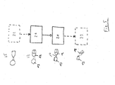
- FIG. 5 shows schematically a possible implementation of the invention Process.
- a blank 24 is provided with a shaft housing and a ball housing.
- the blank 24 may have been produced in an immediately preceding step 20, namely from a semi-finished product 25.
- a taper is introduced, preferably by cold forming.
- the shaft housing 12 is formed on the blank 24, namely a transition region of the blank between the shaft housing 12 and the ball housing 13 over the entire cross section.
- the ball housing 13 can be bent relative to the shaft housing 12 in a subsequent method step 23. It can be bent predominantly or exclusively, the transition region 14. As a result, an arbitrary angular alignment of the shaft housing 12 with the ball housing 13 can basically be achieved.
Landscapes
- Engineering & Computer Science (AREA)
- General Engineering & Computer Science (AREA)
- Mechanical Engineering (AREA)
- Steering-Linkage Mechanisms And Four-Wheel Steering (AREA)
Abstract
Description
- Die Erfindung betrifft ein Gelenkgehäuse für eine Spurstange, mit einem Schaftgehäuse zur Verbindung mit einem Axialzapfen und einem Kugelgehäuse zur Aufnahme eines Kugelgelenks. Zudem betrifft die Erfindung ein Verfahren zur Herstellung eines Gelenkgehäuses für eine Spurstange, wobei ein Rohling bereitgestellt wird, wobei aus einem Bereich des Rohlings ein Schaftgehäuse zur Verbindung mit einem Axialzapfen und aus einem anderen Bereich des Rohlings ein Kugelgehäuse zur Aufnahme eines Kugelgelenks ausgebildet wird
- Derartige Gelenkgehäuse sind hinlänglich aus dem Stand der Technik bekannt, beispielsweise aus der
DE 10 2008 053 796 A1 . Ein solches Gelenkgehäuse dient dazu, den Axialzapfen einer Spurstange gelenkig mit einem Radträger eines Fahrzeuges zu verbinden. Das Schaftgehäuse dient hierbei der Aufnahme des Axialzapfens. Der Axialzapfen kann beispielsweise in eine Bohrung mit Innengewinde des Schaftgehäuses eingeschraubt werden. Das Kugelgehäuse dient der Verbindung mit dem Radträger. Hierzu stellt das Kugelgehäuse eine sphärische Aufnahme bereit, in welcher eine mit dem Radträger verbindbare Kugel beweglich gelagert werden kann. Diese Anordnung erlaubt Rotationen zwischen dem Radträger und dem Axialzapfen um alle drei Raumrichtungen. - Das Schaftgehäuse und das Kugelgehäuse gehen durch einen Übergangsbereich ineinander über. Der Übergangsbereich verbindet somit das Schaftgehäuse mit dem Kugelgehäuse.
- Das Schaftgehäuse muss konstruktionsbedingt einen Mindestdurchmesser aufweisen, welcher sich in Abhängigkeit der im Schaftgehäuse vorgesehenen Bohrung mit Innengewinde zur Aufnahme des Axialzapfens ergibt. An das Kugelgehäuse können hingegen ganz andere geometrische beziehungsweise mechanische Anforderungen bestehen. Es ist daher aus dem Stand der Technik bekannt den Übergangsbereich "platt zu drücken". Dies geschieht bislang beispielsweise durch Zerspanen oder Schmieden. Der aus dem Stand der Technik bekannte "platt gedrückte" Übergangsbereich zeichnet sich dadurch aus, dass er zwar mit Bezug auf eine erste Raumrichtung gegenüber dem Durchmesser des Schaftgehäuses reduziert ist, mit Bezug auf eine zweite Raumrichtung jedoch genauso breit oder sogar breiter als das Schaftgehäuse ist. Dies ist anschaulich in den beiden Figuren der
DE 10 2008 053 796 A1 dargestellt. - Wenngleich sich die aus dem Stand der Technik bekannten Gelenkgehäuse bewährt haben, besteht dennoch Verbesserungsbedarf. So sind mit den bekannten Verfahren zur Zerspanung oder zum Schmieden des Übergangsbereichs hohe Kosten, eine unzureichende Nachhaltigkeit sowie gestalterische Einschränkungen bei der Konstruktion des Gelenkgehäuses verbunden.
- Vor diesem Hintergrund ist es die Aufgabe der vorliegenden Erfindung, ein gattungsgemäßes Gelenkgehäuse kostengünstiger und nachhaltiger herstellen zu können sowie eine größere gestalterische Freiheit bei der Konstruktion zu ermöglichen.
- Zur Lösung schlägt die Erfindung vor, dass das Schaftgehäuse und dass das Kugelgehäuse durch einen über den gesamten Querschnitt verjüngten Übergangsbereich miteinander verbunden sind.
- Erfindungsgemäß ist der Querschnitt des Übergangsbereichs also nicht mehr nur, wie aus dem Stand der Technik bekannt, in bestimmten Raumrichtungen verjüngt, sondern vielmehr über den gesamten Querschnitt. Dies bedeutet mit Bezug auf die Gelenkachse des Schaftgehäuses, dass an jeder beliebigen Stelle in Umfangsrichtung eine Verjüngung beziehungsweise Verkleinerung des Querschnitts des Übergangsbereichs gegenüber dem Querschnitt des Schaftgehäuses ausgebildet ist. Der Übergangsbereich ist in jeder radialen Richtung von der Außenoberfläche des Schaftgehäuses beabstandet. Das Schaftgehäuse geht durch eine Art vollumfänglichen Wellenabsatz in den Übergangsbereich über. Der Durchmesser des Übergangsbereichs ist gegenüber dem Durchmesser des Schaftgehäuses reduziert. Die Querschnittskontur des Übergangsbereichs und/oder des Schaftgehäuses kann kreisrund ausgebildet sein.
- Im Unterschied zum Stand der Technik ist der Übergangsbereich nicht durch Zerspanen oder Schmieden bearbeitet, sondern durch Kaltumformung. Kaltumformung bezeichnet das Umformen von Metallen bei einer Temperatur deutlich unterhalb der Rekristallisationstemperatur. Der Vorteil des Kaltumformens liegt darin, dass entweder keine weitere Nachbearbeitung oder nur eine geringe Nacharbeit erforderlich ist. Durch das Kaltumformen können bereits sehr kleine Maßtoleranzen erreicht werden. Der Übergangsbereich kann somit durch Kaltumformen "(near) net shape" gebildet werden. Hinzu kommt, dass sich die Festigkeit des kaltumgeformten Materials durch Kaltverfestigung erhöht.
- Das erfindungsgemäße Gelenkgehäuse weist einen Übergangsbereich auf, der über den gesamten Querschnitt verjüngt ausgebildet ist, insbesondere gegenüber dem Schaftgehäuse. Dies bringt den Vorteil mit sich, dass das Kugelgehäuse relativ zum Schaftgehäuse besonders leicht dreidimensional gebogen werden kann. Eine solche dreidimensionale Biegung kann je nach Einsatzzweck der Spurstange erforderlich sein. Durch den über den gesamten Querschnitt verjüngten Übergangsbereich kann erreicht werden, dass die Biegesteifigkeit des Übergangsbereichs in beiden Raumrichtungen rechtwinklig zur Längsachse des Schaftgehäuses gleich ausgebildet ist. Dadurch bestehen gegenüber dem aus dem Stand der Technik bekannten Gelenkgehäuse größere gestalterische Freiheiten bei der Konstruktion des Gelenkgehäuses. Es können auch solche Biegungen zwischen Schaftgehäuse einerseits und Kugelgehäuse andererseits erreicht werden, die bei den aus dem Stand der Technik bekannten Lösungen gar nicht möglich waren.
- Hinzu kommt, dass der Übergangsbereich nach dem Biegevorgang unter Umständen nicht nachbearbeitet werden muss, da die gewünschte Geometrie und die gewünschten
- Eigenschaften bereits durch die Kaltumformung endfertig erreicht wurden. Insofern vereinfacht sich die Herstellung des erfindungsgemäßen Gelenkgehäuses erheblich. Hinzu kommt, dass beim Kaltumformen keine Späne anfallen wie beim Zerspanen, die dann entsorgt werden müssen. Insofern kann ein erfindungsgemäßes Gelenkgehäuse auch nachhaltiger hergestellt werden.
- Gemäß einer vorteilhaften Weiterbildung der Erfindung sind die Querschnitskonturen des Schaftgehäuses und des Übergangsbereichs gleich ausgebildet, die Querschnittskonturen des Übergangsbereichs jedoch kleiner skaliert ausgebildet. Dies bedeutet, dass die beiden Querschnittskonturen qualitativ gleich geformt sind. Die Querschnittskontur des Übergangsbereichs ist jedoch im Verhältnis kleiner skaliert als die Querschnittskontur des Schaftgehäuses. Ein Verbindungsbereich zwischen der Außenoberfläche des Schaftgehäuses und der Außenoberfläche des Übergangsbereichs ist über den gesamten Umfang gleich ausgebildet. Dies vereinfacht die weitere Bearbeitung des Gelenkgehäuses, wobei auch konstruktiv sehr aufwendige Gestaltungen ermöglicht werden.
- Gemäß einer vorteilhaften Weiterbildung der Erfindung verlaufen der Übergangsbereich und das Schaftgehäuse zumindest teilweise koaxial. Ihre Längsachsen könnten jedoch auch exzentrisch verlaufen. Der Übergangsbereich und das Schaftgehäuse können sich zumindest teilweise in parallelen Richtungen erstrecken. Der Übergangsbereich und/oder das Schaftgehäuse können rotationssymetrisch ausgebildet sein.
- Der Übergangsbereich kann mit Bezug auf seine Längsachse gekrümmt ausgebildet sein. Die Krümmung kann um eine oder kombiniert um zwei Achsen ausgebildet sein. Diese Achsen verlaufen radial zur Längsachse und sind linear unabhängig. Dies bedeutet, dass sich sowohl das Kugelgehäuse als auch das Schaftgehäuse gerade erstrecken können. Eine winklige Anordnung zueinander wird durch den gekrümmten Übergangsbereich erreicht. Der Übergangsbereich kann besonders einfach gekrümmt werden, da er über dem gesamten Querschnitt gegenüber dem Schaftgehäuse und/oder dem Kugelgehäuse verjüngt ausgebildet ist. Gekrümmt im Sinne der Erfindung umfasst einen bogenförmigen Verlauf, einen Knick, das heißt spitzen Verlauf und/oder dergleichen.
- Verfahrensseitig wird zur Lösung vorgeschlagen, dass am Rohling ein Übergangsbereich zwischen dem Bereich für das Schaftgehäuse und dem Bereich für das Kugelgehäuse über den gesamten Querschnitt verjüngt wird.
- Im Unterschied zum Stand der Technik, beispielsweise in Form der
DE 10 2008 053 796 A1 , wird dieser Übergangsbereich also nicht nur partiell, sondern vielmehr über den gesamten Querschnitt verjüngt. Dies bedeutet, dass über den gesamten Umfang des Übergangsbereichs eine Verjüngung stattfindet. Der Übergangsbereich kann rotationssymmetrisch verjüngt werden. - Der Übergangsbereich kann verjüngt werden, bevor das Schaftgehäuse und das Kugelgehäuse ausgebildet werden. Er kann jedoch auch erst anschließend oder zusammen mit dem Schaftgehäuse und/oder dem Kugelgehäuse ausgebildet werden. Vorzugsweise wird der Übergangsbereich durch Kaltumformung verjüngt. Dies wurde vorstehend bereits erläutert.
- Ein nach dem erfindungsgemäßen Verfahren hergestelltes Gelenkgehäuse hat den Vorteil, dass eine Verbiegung zwischen Schaftgehäuse und Kugelgehäuse einfacher und hinsichtlich der Gestaltungsfreiheit flexibler möglich ist. Zudem führt die Verjüngung über den gesamten Querschnitt zu einer deutlichen Gewichtsreduktion, sodass ein nach dem erfindungsgemäßen Verfahren hergestelltes Gelenkgehäuse als Leichtbau-Gelenkgehäuse bezeichnet werden kann.
- Weitere Vorteile und Merkmale der Erfindung ergeben sich aus der nachfolgenden Figurenbeschreibung. Es zeigen:
- Figur 1:
- ein aus dem Stand der Technik bekanntes Gelenkgehäuse im Längsschnitt;
- Figur 2:
- das aus dem Stand der Technik bekannte Gelenkgehäuse gemäß
Figur 1 in Draufsicht; - Figur 3:
- eine Ausführungsform eines erfindungsgemäßen Gelenkgehäuses in perspektivischer Darstellung;
- Figur 4:
- eine Schnittansicht entlang der Linie IV - IV in
Figur 3 . - Figur 5:
- schematisch die Durchführung eines erfindungsgemäßen Verfahrens.
-
Figur 1 zeigt ein Gelenkgehäuse 1 nach dem Stand der Technik. Dieses weist ein Schaftgehäuse 2 sowie ein Kugelgehäuse 3 auf. Das Schaftgehäuse 2 und das Kugelgehäuse 3 sind durch einen Übergangsbereich 4 miteinander verbunden. Im Schaftgehäuse 2 ist eine Gewindebohrung 5 vorgesehen, welche über einen Gewindebereich 9 als Innengewinde verfügt. Das Innengewinde weist einen Gewindekerndurchmesser 7 auf. Das Schaftgehäuse 2 ist im Querschnitt kreisrund ausgebildet. An den kreisrunden Querschnitt schließt sich eine endseitig vorgesehene Schlüsselfläche 6 an. Diese ist als Außensechskant ausgebildet. In die Gewindebohrung 5 kann ein mit einem entsprechenden Außengewinde versehener Axialzapfen eingeschraubt werden. - Das Kugelgehäuse 3 weist in
Figur 1 ein Durchgangsloch 8 auf. Das Kugelgehäuse 3 könnte aber auch einseitig geschlossen ausgeführt sein. In diesem Durchgangsloch 8 kann eine Kugel aufgenommen werden. Die Kugel kann an einem Radträger eines Fahrzeugs angeordnet werden. - In Zusammenschau mit
Figur 2 wird deutlich, dass der Übergangsbereich 4 zwar in Richtung der Längsachse des Durchgangslochs 8 mit Bezug auf das Schaftgehäuse 2 und das Kugelgehäuse 3 verjüngt ist. Jedoch ist der Übergangsbereich 4 in einer Richtung radial zum Durchgangsloch zumindest gegenüber dem Schaftgehäuse 2 deutlich verbreitert. Diese Ausbildung des Übergangsbereichs 4 gemäß dem Stand der Technik kann als plattgedrückt bezeichnet werden. -
Figur 3 zeigt hingegen eine Ausführungsform eines erfindungsgemäßen Gelenkgehäuses 11. Dieses weist ein Schaftgehäuse 12 und ein Kugelgehäuse 13 auf. Das Schaftgehäuse 12 und das Kugelgehäuse 13 sind durch einen Übergangsbereich 14 miteinander verbunden. Das gesamte Gelenkgehäuse 11 kann einstückig, insbesondere aus einem Guss ausgebildet sein. - Das Schaftgehäuse 12 weist eine kreisrunde Querschnittskontur auf. Lediglich an einem dem Kugelgehäuse 13 gegenüberliegenden Ende ist eine Schlüsselfläche 16 vorgesehen. Diese ist als Außensechskant ausgebildet. An diesem dem Kugelgehäuse 13 abgewandten Ende ist zudem eine Gewindebohrung 15 in das Schaftgehäuse 12 eingebracht. Die Gewindebohrung ist zentrisch im Schaftgehäuse 12 ausgebildet. Sie weist ein Innengewinde auf.
- Der Übergangsbereich 14 ist gegenüber dem Schaftgehäuse 12 verjüngt ausgebildet. Der Übergangsbereich 14 ist gegenüber dem gesamten Querschnitt verjüngt ausgebildet. Der Übergangsbereich ist im Querschnitt kreisrund ausgebildet. Der Übergangsbereich 14 und das Schaftgehäuse 12 verlaufen koaxial. Der Übergangsbereich 14 kann gekrümmt ausgebildet sein, sodass das Kugelgehäuse 13 und das Schaftgehäuse 12 winklig zueinander ausgerichtet sein können. Die Krümmung kann um die y-Achse und/oder die z-Achse in
Figur 3 ausgebildet sein. -
Figur 4 zeigt eine Querschnittsansicht entlang der Linie IV - IV. inFigur 3 . Zu sehen ist der geschnittene Übergangsbereich 14. Hinter diesem Übergangsbereich 14 ist die Querschnittskontur des Schaftgehäuses 12 zu sehen. Das Schaftgehäuse 12 ist im Querschnitt kreisrund. Der Übergangsbereich 14 ist im Querschnitt ebenfalls kreisrund. Beide Teile verlaufen koaxial zueinander. Sie verfügen somit über eine gemeinsame Längsachse 17. - Der Durchmesser 18 des Schaftgehäuses 12 ist größer als der Durchmesser 19 des Übergangsbereichs 14. Die Außenoberfläche des Übergangsbereichs 14 ist in jeder beliebigen radialen Richtung von der Außenoberfläche des Schaftgehäuses 12 beabstandet. Die Verjüngung des Übergangsbereichs 14 wird bevorzugt durch Kaltumformen ausgebildet.
-
Figur 5 zeigt schematisch eine mögliche Durchführung des erfindungsgemäßen Verfahrens. In einem Schritt 20 wird ein Rohling 24 mit einem Schaftgehäuse und einem Kugelgehäuse bereitgestellt. Der Rohling 24 kann in einem unmittelbar vorangegangenen Schritt 20 hergestellt worden sein, und zwar aus einem Halbzeug 25. In das Halbzeug 25 wird eine Verjüngung eingebracht, vorzugsweise durch Kaltumformen. - In einem Schritt 21 wird das Schaftgehäuse 12 am Rohling 24 ausgeformt, und zwar ein Übergangsbereich des Rohlings zwischen dem Schaftgehäuse 12 und dem Kugelgehäuse 13 über den gesamten Querschnitt.
- Je nach Anwendung des herzustellenden Gelenkgehäuses kann das Kugelgehäuse 13 relativ zum Schaftgehäuse 12 in einem nachfolgenden Verfahrensschritt 23 gebogen werden. Es kann überwiegend oder ausschließlich der Übergangsbereich 14 gebogen werden. Dadurch lässt sich dem Grunde nach eine beliebige winklige Ausrichtung des Schaftgehäuses 12 zum Kugelgehäuse 13 erreichen.
-
- 1
- Gelenkgehäuse
- 2
- Schaftgehäuse
- 3
- Kugelgehäuse
- 4
- Übergangsbereich
- 5
- Gewindebohrung
- 6
- Schlüsselfläche
- 7
- Gewindekerndurchmesser
- 8
- Durchgangsloch
- 9
- Gewindebereich
- 11
- Gefenkgehäuse
- 12
- Schaftgehäuse
- 13
- Kugelgehäuse
- 14
- Übergangsbereich
- 15
- Gewindebohrung
- 16
- Schlüsselfläche
- 17
- Längsachse
- 18
- Durchmesser
- 19
- Durchmesser
- 20
- Bereitstellen
- 21
- Verjüngen
- 22
- Herstellen
- 23
- Biegen
- 24
- Rohling
- 25
- Halbzeug
Claims (11)
- Gelenkgehäuse (11) für eine Spurstange, mit einem Schaftgehäuse (12) zur Verbindung mit einem Axialzapfen und einem Kugelgehäuse (13) zur Aufnahme eines Kugelgelenks, dadurch gekennzeichnet, dass das Schaftgehäuse (12) und das Kugelgehäuse (13) durch einen über den gesamten Querschnitt verjüngten Übergangsbereich (14) miteinander verbunden sind.
- Gelenkgehäuse nach Anspruch 1, dadurch gekennzeichnet, dass der Übergangsbereich (14) über den gesamten Querschnitt gegenüber dem Schaftgehäuses (12) verjüngt ausgebildet ist.
- Gelenkgehäuse nach einem der vorangehenden Ansprüche, dadurch gekennzeichnet, dass die Querschnittskonturen des Schaftgehäuses (12) und des Übergangsbereichs (14) gleich ausgebildet sind, die Querschnittskontur des Übergangsbereichs (14) jedoch kleiner skaliert ausgebildet ist.
- Gelenkgehäuse nach einem der vorangehenden Ansprüche, dadurch gekennzeichnet, dass der Übergangsbereich (14) und das Schaftgehäuse (12) zumindest teilweise koaxial verlaufen.
- Gelenkgehäuse nach einem der vorangehenden Ansprüche, dadurch gekennzeichnet, dass die Querschnittskontur des Übergangsbereichs (14) kreisrund ausgebildet ist.
- Gelenkgehäuse nach einem der vorangehenden Ansprüche, dadurch gekennzeichnet, dass der Übergangsbereich (14) mit Bezug auf seine Längsachse (17) gekrümmt ausgebildet ist.
- Gelenkgehäuse nach einem der vorangehenden Ansprüche, dadurch gekennzeichnet, dass das Schaftgehäuse (12) eine axiale Bohrung (15) mit Innengewinde zur Aufnahme des Axialzapfens aufweist.
- Verfahren zur Herstellung eines Gelenkgehäuses (11) für eine Spurstange, wobei ein Rohling (24) bereitgestellt (20) wird, wobei aus einem Bereich des Rohlings (24) ein Schaftgehäuse (12) zur Verbindung mit einem Axialzapfen und aus einem anderen Bereich des Rohlings (24) ein Kugelgehäuse zur Aufnahme eines Kugelgelenks (13) ausgebildet wird, dadurch gekennzeichnet, dass am Rohling (24) ein Übergangsbereich zwischen dem Bereich für das Schaftgehäuse (12) und dem Bereich für das Kugelgehäuse (13) über den gesamten Querschnitt verjüngt (21) wird.
- Verfahren nach Anspruch 8, dadurch gekennzeichnet, dass der Übergangsbereich (14) durch Kaltumformung verjüngt wird.
- Verfahren nach Anspruch 8 oder 9, dadurch gekennzeichnet, dass nach der Verjüngung des Übergangsbereichs (14) das Kugelgehäuse (13) relativ zum Schaftgehäuse (12) gebogen (23) wird.
- Verfahren nach einem der Ansprüche 8 bis 10, dadurch gekennzeichnet, dass der Übergangsbereich (14) über seinen gesamten Umfang verjüngt (21) und kaltumgeformt wird.
Priority Applications (1)
| Application Number | Priority Date | Filing Date | Title |
|---|---|---|---|
| EP14179161.6A EP2979773B1 (de) | 2014-07-30 | 2014-07-30 | Gelenkgehäuse für eine Spurstange und Verfahren zu seiner Herstellung |
Applications Claiming Priority (1)
| Application Number | Priority Date | Filing Date | Title |
|---|---|---|---|
| EP14179161.6A EP2979773B1 (de) | 2014-07-30 | 2014-07-30 | Gelenkgehäuse für eine Spurstange und Verfahren zu seiner Herstellung |
Publications (2)
| Publication Number | Publication Date |
|---|---|
| EP2979773A1 true EP2979773A1 (de) | 2016-02-03 |
| EP2979773B1 EP2979773B1 (de) | 2020-09-02 |
Family
ID=51228372
Family Applications (1)
| Application Number | Title | Priority Date | Filing Date |
|---|---|---|---|
| EP14179161.6A Active EP2979773B1 (de) | 2014-07-30 | 2014-07-30 | Gelenkgehäuse für eine Spurstange und Verfahren zu seiner Herstellung |
Country Status (1)
| Country | Link |
|---|---|
| EP (1) | EP2979773B1 (de) |
Cited By (1)
| Publication number | Priority date | Publication date | Assignee | Title |
|---|---|---|---|---|
| CN107350407A (zh) * | 2016-05-09 | 2017-11-17 | 艾尔弗雷德·图恩有限责任两合公司 | 用于材料的改型的多阶段的方法 |
Citations (6)
| Publication number | Priority date | Publication date | Assignee | Title |
|---|---|---|---|---|
| DE1875317U (de) * | 1963-03-06 | 1963-07-11 | Wilhelm Woeltje | Kugelgelenk fuer lenk-, schub- und spurstangen. |
| US4202082A (en) * | 1975-04-03 | 1980-05-13 | Incom International Inc. | Method of manufacturing spherical bearings and parts therefor |
| JPS58112626A (ja) * | 1981-12-26 | 1983-07-05 | Musashi Seimitsu Kogyo Kk | トランスフア−プレスによるタイロツドエンドハウジング冷間鍛造方法 |
| EP0766015A1 (de) * | 1995-09-28 | 1997-04-02 | TRW Fahrwerksysteme GmbH & Co. KG | Verfahren zur Herstellung eines Gelenkgehäuses |
| WO2004039529A1 (de) * | 2002-10-24 | 2004-05-13 | ZF Lemförder Metallwaren AG | Verfahren zur herstellung eines spurstangengehäuses |
| DE102008053796A1 (de) | 2008-10-29 | 2010-05-06 | Presswerk Krefeld Gmbh & Co.Kg | Verfahren zur Herstellung eines Gelenkgehäuses |
-
2014
- 2014-07-30 EP EP14179161.6A patent/EP2979773B1/de active Active
Patent Citations (6)
| Publication number | Priority date | Publication date | Assignee | Title |
|---|---|---|---|---|
| DE1875317U (de) * | 1963-03-06 | 1963-07-11 | Wilhelm Woeltje | Kugelgelenk fuer lenk-, schub- und spurstangen. |
| US4202082A (en) * | 1975-04-03 | 1980-05-13 | Incom International Inc. | Method of manufacturing spherical bearings and parts therefor |
| JPS58112626A (ja) * | 1981-12-26 | 1983-07-05 | Musashi Seimitsu Kogyo Kk | トランスフア−プレスによるタイロツドエンドハウジング冷間鍛造方法 |
| EP0766015A1 (de) * | 1995-09-28 | 1997-04-02 | TRW Fahrwerksysteme GmbH & Co. KG | Verfahren zur Herstellung eines Gelenkgehäuses |
| WO2004039529A1 (de) * | 2002-10-24 | 2004-05-13 | ZF Lemförder Metallwaren AG | Verfahren zur herstellung eines spurstangengehäuses |
| DE102008053796A1 (de) | 2008-10-29 | 2010-05-06 | Presswerk Krefeld Gmbh & Co.Kg | Verfahren zur Herstellung eines Gelenkgehäuses |
Cited By (1)
| Publication number | Priority date | Publication date | Assignee | Title |
|---|---|---|---|---|
| CN107350407A (zh) * | 2016-05-09 | 2017-11-17 | 艾尔弗雷德·图恩有限责任两合公司 | 用于材料的改型的多阶段的方法 |
Also Published As
| Publication number | Publication date |
|---|---|
| EP2979773B1 (de) | 2020-09-02 |
Similar Documents
| Publication | Publication Date | Title |
|---|---|---|
| EP3717793B1 (de) | Verbindungseinrichtung für die anbindung einer dämpfungseinheit eines fahrzeugs innerhalb einer radaufhängung des fahrzeugs | |
| EP2134586B1 (de) | Zahnstange oder gewindestange | |
| EP3625065B1 (de) | Verfahren zur herstellung eines verbindungselementes sowie verbindungselement | |
| DE1804673A1 (de) | Achse fuer Kraftfahrzeuge od.dgl.und Verfahren zu deren Herstellung | |
| DE19536035A1 (de) | Verfahren zur Herstellung eines Gelenkgehäuses | |
| EP3328569B1 (de) | Lenkstange oder spurstange mit einem einteiligen verbindungsrohr | |
| DE102011080266A1 (de) | Verfahren zur formschlüssigen Verbindung zweier zumindest teilweise ineinander angeordneter Rohrabschnitte und Verbindungselement zur winkligen Verbindung zweier Rohrabschnitte | |
| DE102012108423A1 (de) | Zahnstange für ein Lenksystem eines Kraftfahrzeugs, Lenkgetriebe und Druckstück | |
| DE102004057429A1 (de) | Verfahren zum Herstellen von geteilten Rohrstabilisatoren mit Schwenkmotor | |
| EP3513084B1 (de) | Kugelzapfen | |
| DE202019005800U1 (de) | Zweiteilige hochfeste Schraube | |
| EP2979773B1 (de) | Gelenkgehäuse für eine Spurstange und Verfahren zu seiner Herstellung | |
| EP3054182B1 (de) | Verfahren zur herstellung einer fügeverbindung zwischen einem gelenkgehäuse und einem anbindungsbauteil, sowie verfahrensgemäss hergestelltes fahrwerkbauteil | |
| WO2004110796A1 (de) | Wattstrebe | |
| DE102007000950B4 (de) | Zahnstange und Verfahren zur Herstellung | |
| WO2017220202A9 (de) | Verfahren zur herstellung einer kolbenstangen-einheit sowie einer hohlen welle | |
| EP3524836A1 (de) | Axialkugelzapfen | |
| DE102018124493B4 (de) | Gelenkgehäuse und Verfahren zur Herstellung eines Gelenkgehäuses | |
| DE102010008164A1 (de) | Verfahren zur Anbindung einer Rohrstabilisatorhälfte und Rohrstabilisator | |
| DE10241929A1 (de) | Joch für ein Universalgelenk und Herstellungsverfahren hierfür | |
| DE102014107896A1 (de) | Flanschplatte zum Anbinden einer Verbundlenkerachse an ein Radlager | |
| EP1507983B1 (de) | Gehäuse zur aufnahme eines lagerbauteiles und verfahren zu dessen herstellung | |
| EP2123375A1 (de) | Hohler Pleuel | |
| EP2280802B1 (de) | Geschweisster kugelzapfen und herstellungsverfahren dafür | |
| EP4703160A1 (de) | Fahrwerksstrebe für fahrzeuge, insbesondere kraftfahrzeuge, sowie verfahren zur herstellung einer solchen fahrwerksstrebe |
Legal Events
| Date | Code | Title | Description |
|---|---|---|---|
| PUAI | Public reference made under article 153(3) epc to a published international application that has entered the european phase |
Free format text: ORIGINAL CODE: 0009012 |
|
| AK | Designated contracting states |
Kind code of ref document: A1 Designated state(s): AL AT BE BG CH CY CZ DE DK EE ES FI FR GB GR HR HU IE IS IT LI LT LU LV MC MK MT NL NO PL PT RO RS SE SI SK SM TR |
|
| AX | Request for extension of the european patent |
Extension state: BA ME |
|
| 17P | Request for examination filed |
Effective date: 20160727 |
|
| RBV | Designated contracting states (corrected) |
Designated state(s): AL AT BE BG CH CY CZ DE DK EE ES FI FR GB GR HR HU IE IS IT LI LT LU LV MC MK MT NL NO PL PT RO RS SE SI SK SM TR |
|
| STAA | Information on the status of an ep patent application or granted ep patent |
Free format text: STATUS: EXAMINATION IS IN PROGRESS |
|
| 17Q | First examination report despatched |
Effective date: 20181122 |
|
| GRAP | Despatch of communication of intention to grant a patent |
Free format text: ORIGINAL CODE: EPIDOSNIGR1 |
|
| STAA | Information on the status of an ep patent application or granted ep patent |
Free format text: STATUS: GRANT OF PATENT IS INTENDED |
|
| INTG | Intention to grant announced |
Effective date: 20200409 |
|
| GRAS | Grant fee paid |
Free format text: ORIGINAL CODE: EPIDOSNIGR3 |
|
| GRAA | (expected) grant |
Free format text: ORIGINAL CODE: 0009210 |
|
| STAA | Information on the status of an ep patent application or granted ep patent |
Free format text: STATUS: THE PATENT HAS BEEN GRANTED |
|
| AK | Designated contracting states |
Kind code of ref document: B1 Designated state(s): AL AT BE BG CH CY CZ DE DK EE ES FI FR GB GR HR HU IE IS IT LI LT LU LV MC MK MT NL NO PL PT RO RS SE SI SK SM TR |
|
| REG | Reference to a national code |
Ref country code: GB Ref legal event code: FG4D Free format text: NOT ENGLISH |
|
| REG | Reference to a national code |
Ref country code: AT Ref legal event code: REF Ref document number: 1308246 Country of ref document: AT Kind code of ref document: T Effective date: 20200915 Ref country code: CH Ref legal event code: EP |
|
| REG | Reference to a national code |
Ref country code: DE Ref legal event code: R096 Ref document number: 502014014692 Country of ref document: DE |
|
| REG | Reference to a national code |
Ref country code: IE Ref legal event code: FG4D Free format text: LANGUAGE OF EP DOCUMENT: GERMAN |
|
| REG | Reference to a national code |
Ref country code: LT Ref legal event code: MG4D |
|
| REG | Reference to a national code |
Ref country code: SK Ref legal event code: T3 Ref document number: E 35839 Country of ref document: SK |
|
| PG25 | Lapsed in a contracting state [announced via postgrant information from national office to epo] |
Ref country code: BG Free format text: LAPSE BECAUSE OF FAILURE TO SUBMIT A TRANSLATION OF THE DESCRIPTION OR TO PAY THE FEE WITHIN THE PRESCRIBED TIME-LIMIT Effective date: 20201202 Ref country code: SE Free format text: LAPSE BECAUSE OF FAILURE TO SUBMIT A TRANSLATION OF THE DESCRIPTION OR TO PAY THE FEE WITHIN THE PRESCRIBED TIME-LIMIT Effective date: 20200902 Ref country code: NO Free format text: LAPSE BECAUSE OF FAILURE TO SUBMIT A TRANSLATION OF THE DESCRIPTION OR TO PAY THE FEE WITHIN THE PRESCRIBED TIME-LIMIT Effective date: 20201202 Ref country code: HR Free format text: LAPSE BECAUSE OF FAILURE TO SUBMIT A TRANSLATION OF THE DESCRIPTION OR TO PAY THE FEE WITHIN THE PRESCRIBED TIME-LIMIT Effective date: 20200902 Ref country code: LT Free format text: LAPSE BECAUSE OF FAILURE TO SUBMIT A TRANSLATION OF THE DESCRIPTION OR TO PAY THE FEE WITHIN THE PRESCRIBED TIME-LIMIT Effective date: 20200902 Ref country code: FI Free format text: LAPSE BECAUSE OF FAILURE TO SUBMIT A TRANSLATION OF THE DESCRIPTION OR TO PAY THE FEE WITHIN THE PRESCRIBED TIME-LIMIT Effective date: 20200902 Ref country code: GR Free format text: LAPSE BECAUSE OF FAILURE TO SUBMIT A TRANSLATION OF THE DESCRIPTION OR TO PAY THE FEE WITHIN THE PRESCRIBED TIME-LIMIT Effective date: 20201203 |
|
| REG | Reference to a national code |
Ref country code: NL Ref legal event code: MP Effective date: 20200902 |
|
| PG25 | Lapsed in a contracting state [announced via postgrant information from national office to epo] |
Ref country code: LV Free format text: LAPSE BECAUSE OF FAILURE TO SUBMIT A TRANSLATION OF THE DESCRIPTION OR TO PAY THE FEE WITHIN THE PRESCRIBED TIME-LIMIT Effective date: 20200902 Ref country code: RS Free format text: LAPSE BECAUSE OF FAILURE TO SUBMIT A TRANSLATION OF THE DESCRIPTION OR TO PAY THE FEE WITHIN THE PRESCRIBED TIME-LIMIT Effective date: 20200902 |
|
| PG25 | Lapsed in a contracting state [announced via postgrant information from national office to epo] |
Ref country code: EE Free format text: LAPSE BECAUSE OF FAILURE TO SUBMIT A TRANSLATION OF THE DESCRIPTION OR TO PAY THE FEE WITHIN THE PRESCRIBED TIME-LIMIT Effective date: 20200902 Ref country code: PT Free format text: LAPSE BECAUSE OF FAILURE TO SUBMIT A TRANSLATION OF THE DESCRIPTION OR TO PAY THE FEE WITHIN THE PRESCRIBED TIME-LIMIT Effective date: 20210104 Ref country code: NL Free format text: LAPSE BECAUSE OF FAILURE TO SUBMIT A TRANSLATION OF THE DESCRIPTION OR TO PAY THE FEE WITHIN THE PRESCRIBED TIME-LIMIT Effective date: 20200902 Ref country code: RO Free format text: LAPSE BECAUSE OF FAILURE TO SUBMIT A TRANSLATION OF THE DESCRIPTION OR TO PAY THE FEE WITHIN THE PRESCRIBED TIME-LIMIT Effective date: 20200902 Ref country code: SM Free format text: LAPSE BECAUSE OF FAILURE TO SUBMIT A TRANSLATION OF THE DESCRIPTION OR TO PAY THE FEE WITHIN THE PRESCRIBED TIME-LIMIT Effective date: 20200902 |
|
| PG25 | Lapsed in a contracting state [announced via postgrant information from national office to epo] |
Ref country code: AL Free format text: LAPSE BECAUSE OF FAILURE TO SUBMIT A TRANSLATION OF THE DESCRIPTION OR TO PAY THE FEE WITHIN THE PRESCRIBED TIME-LIMIT Effective date: 20200902 Ref country code: ES Free format text: LAPSE BECAUSE OF FAILURE TO SUBMIT A TRANSLATION OF THE DESCRIPTION OR TO PAY THE FEE WITHIN THE PRESCRIBED TIME-LIMIT Effective date: 20200902 Ref country code: IS Free format text: LAPSE BECAUSE OF FAILURE TO SUBMIT A TRANSLATION OF THE DESCRIPTION OR TO PAY THE FEE WITHIN THE PRESCRIBED TIME-LIMIT Effective date: 20210102 |
|
| REG | Reference to a national code |
Ref country code: DE Ref legal event code: R097 Ref document number: 502014014692 Country of ref document: DE |
|
| PLBE | No opposition filed within time limit |
Free format text: ORIGINAL CODE: 0009261 |
|
| STAA | Information on the status of an ep patent application or granted ep patent |
Free format text: STATUS: NO OPPOSITION FILED WITHIN TIME LIMIT |
|
| 26N | No opposition filed |
Effective date: 20210603 |
|
| PG25 | Lapsed in a contracting state [announced via postgrant information from national office to epo] |
Ref country code: DK Free format text: LAPSE BECAUSE OF FAILURE TO SUBMIT A TRANSLATION OF THE DESCRIPTION OR TO PAY THE FEE WITHIN THE PRESCRIBED TIME-LIMIT Effective date: 20200902 Ref country code: SI Free format text: LAPSE BECAUSE OF FAILURE TO SUBMIT A TRANSLATION OF THE DESCRIPTION OR TO PAY THE FEE WITHIN THE PRESCRIBED TIME-LIMIT Effective date: 20200902 |
|
| PG25 | Lapsed in a contracting state [announced via postgrant information from national office to epo] |
Ref country code: IT Free format text: LAPSE BECAUSE OF FAILURE TO SUBMIT A TRANSLATION OF THE DESCRIPTION OR TO PAY THE FEE WITHIN THE PRESCRIBED TIME-LIMIT Effective date: 20200902 |
|
| REG | Reference to a national code |
Ref country code: CH Ref legal event code: PL |
|
| GBPC | Gb: european patent ceased through non-payment of renewal fee |
Effective date: 20210730 |
|
| PG25 | Lapsed in a contracting state [announced via postgrant information from national office to epo] |
Ref country code: MC Free format text: LAPSE BECAUSE OF FAILURE TO SUBMIT A TRANSLATION OF THE DESCRIPTION OR TO PAY THE FEE WITHIN THE PRESCRIBED TIME-LIMIT Effective date: 20200902 |
|
| REG | Reference to a national code |
Ref country code: BE Ref legal event code: MM Effective date: 20210731 |
|
| PG25 | Lapsed in a contracting state [announced via postgrant information from national office to epo] |
Ref country code: LI Free format text: LAPSE BECAUSE OF NON-PAYMENT OF DUE FEES Effective date: 20210731 Ref country code: GB Free format text: LAPSE BECAUSE OF NON-PAYMENT OF DUE FEES Effective date: 20210730 Ref country code: CH Free format text: LAPSE BECAUSE OF NON-PAYMENT OF DUE FEES Effective date: 20210731 |
|
| PG25 | Lapsed in a contracting state [announced via postgrant information from national office to epo] |
Ref country code: LU Free format text: LAPSE BECAUSE OF NON-PAYMENT OF DUE FEES Effective date: 20210730 |
|
| PG25 | Lapsed in a contracting state [announced via postgrant information from national office to epo] |
Ref country code: IE Free format text: LAPSE BECAUSE OF NON-PAYMENT OF DUE FEES Effective date: 20210730 Ref country code: BE Free format text: LAPSE BECAUSE OF NON-PAYMENT OF DUE FEES Effective date: 20210731 |
|
| REG | Reference to a national code |
Ref country code: AT Ref legal event code: MM01 Ref document number: 1308246 Country of ref document: AT Kind code of ref document: T Effective date: 20210730 |
|
| PG25 | Lapsed in a contracting state [announced via postgrant information from national office to epo] |
Ref country code: AT Free format text: LAPSE BECAUSE OF NON-PAYMENT OF DUE FEES Effective date: 20210730 |
|
| PG25 | Lapsed in a contracting state [announced via postgrant information from national office to epo] |
Ref country code: HU Free format text: LAPSE BECAUSE OF FAILURE TO SUBMIT A TRANSLATION OF THE DESCRIPTION OR TO PAY THE FEE WITHIN THE PRESCRIBED TIME-LIMIT; INVALID AB INITIO Effective date: 20140730 |
|
| PG25 | Lapsed in a contracting state [announced via postgrant information from national office to epo] |
Ref country code: CY Free format text: LAPSE BECAUSE OF FAILURE TO SUBMIT A TRANSLATION OF THE DESCRIPTION OR TO PAY THE FEE WITHIN THE PRESCRIBED TIME-LIMIT Effective date: 20200902 |
|
| PG25 | Lapsed in a contracting state [announced via postgrant information from national office to epo] |
Ref country code: MK Free format text: LAPSE BECAUSE OF FAILURE TO SUBMIT A TRANSLATION OF THE DESCRIPTION OR TO PAY THE FEE WITHIN THE PRESCRIBED TIME-LIMIT Effective date: 20200902 |
|
| PG25 | Lapsed in a contracting state [announced via postgrant information from national office to epo] |
Ref country code: MT Free format text: LAPSE BECAUSE OF FAILURE TO SUBMIT A TRANSLATION OF THE DESCRIPTION OR TO PAY THE FEE WITHIN THE PRESCRIBED TIME-LIMIT Effective date: 20200902 |
|
| PGFP | Annual fee paid to national office [announced via postgrant information from national office to epo] |
Ref country code: DE Payment date: 20250919 Year of fee payment: 12 |
|
| PGFP | Annual fee paid to national office [announced via postgrant information from national office to epo] |
Ref country code: PL Payment date: 20250717 Year of fee payment: 12 |
|
| PGFP | Annual fee paid to national office [announced via postgrant information from national office to epo] |
Ref country code: FR Payment date: 20250725 Year of fee payment: 12 |
|
| PGFP | Annual fee paid to national office [announced via postgrant information from national office to epo] |
Ref country code: CZ Payment date: 20250718 Year of fee payment: 12 |
|
| PGFP | Annual fee paid to national office [announced via postgrant information from national office to epo] |
Ref country code: SK Payment date: 20250725 Year of fee payment: 12 |
|
| PG25 | Lapsed in a contracting state [announced via postgrant information from national office to epo] |
Ref country code: TR Free format text: LAPSE BECAUSE OF FAILURE TO SUBMIT A TRANSLATION OF THE DESCRIPTION OR TO PAY THE FEE WITHIN THE PRESCRIBED TIME-LIMIT Effective date: 20200902 |