EP2979663A1 - Implantable lenses with modified edge regions - Google Patents
Implantable lenses with modified edge regions Download PDFInfo
- Publication number
- EP2979663A1 EP2979663A1 EP15182574.2A EP15182574A EP2979663A1 EP 2979663 A1 EP2979663 A1 EP 2979663A1 EP 15182574 A EP15182574 A EP 15182574A EP 2979663 A1 EP2979663 A1 EP 2979663A1
- Authority
- EP
- European Patent Office
- Prior art keywords
- lens
- region
- interface
- edge
- clause
- Prior art date
- Legal status (The legal status is an assumption and is not a legal conclusion. Google has not performed a legal analysis and makes no representation as to the accuracy of the status listed.)
- Withdrawn
Links
Images


Classifications
-
- A—HUMAN NECESSITIES
- A61—MEDICAL OR VETERINARY SCIENCE; HYGIENE
- A61F—FILTERS IMPLANTABLE INTO BLOOD VESSELS; PROSTHESES; DEVICES PROVIDING PATENCY TO, OR PREVENTING COLLAPSING OF, TUBULAR STRUCTURES OF THE BODY, e.g. STENTS; ORTHOPAEDIC, NURSING OR CONTRACEPTIVE DEVICES; FOMENTATION; TREATMENT OR PROTECTION OF EYES OR EARS; BANDAGES, DRESSINGS OR ABSORBENT PADS; FIRST-AID KITS
- A61F2/00—Filters implantable into blood vessels; Prostheses, i.e. artificial substitutes or replacements for parts of the body; Appliances for connecting them with the body; Devices providing patency to, or preventing collapsing of, tubular structures of the body, e.g. stents
- A61F2/02—Prostheses implantable into the body
- A61F2/14—Eye parts, e.g. lenses, corneal implants; Implanting instruments specially adapted therefor; Artificial eyes
- A61F2/16—Intraocular lenses
-
- A—HUMAN NECESSITIES
- A61—MEDICAL OR VETERINARY SCIENCE; HYGIENE
- A61F—FILTERS IMPLANTABLE INTO BLOOD VESSELS; PROSTHESES; DEVICES PROVIDING PATENCY TO, OR PREVENTING COLLAPSING OF, TUBULAR STRUCTURES OF THE BODY, e.g. STENTS; ORTHOPAEDIC, NURSING OR CONTRACEPTIVE DEVICES; FOMENTATION; TREATMENT OR PROTECTION OF EYES OR EARS; BANDAGES, DRESSINGS OR ABSORBENT PADS; FIRST-AID KITS
- A61F2/00—Filters implantable into blood vessels; Prostheses, i.e. artificial substitutes or replacements for parts of the body; Appliances for connecting them with the body; Devices providing patency to, or preventing collapsing of, tubular structures of the body, e.g. stents
- A61F2/02—Prostheses implantable into the body
- A61F2/14—Eye parts, e.g. lenses, corneal implants; Implanting instruments specially adapted therefor; Artificial eyes
- A61F2/147—Implants to be inserted in the stroma for refractive correction, e.g. ring-like implants
-
- B—PERFORMING OPERATIONS; TRANSPORTING
- B29—WORKING OF PLASTICS; WORKING OF SUBSTANCES IN A PLASTIC STATE IN GENERAL
- B29D—PRODUCING PARTICULAR ARTICLES FROM PLASTICS OR FROM SUBSTANCES IN A PLASTIC STATE
- B29D11/00—Producing optical elements, e.g. lenses or prisms
- B29D11/00009—Production of simple or compound lenses
- B29D11/00028—Bifocal lenses; Multifocal lenses
-
- B—PERFORMING OPERATIONS; TRANSPORTING
- B29—WORKING OF PLASTICS; WORKING OF SUBSTANCES IN A PLASTIC STATE IN GENERAL
- B29D—PRODUCING PARTICULAR ARTICLES FROM PLASTICS OR FROM SUBSTANCES IN A PLASTIC STATE
- B29D11/00—Producing optical elements, e.g. lenses or prisms
- B29D11/02—Artificial eyes from organic plastic material
- B29D11/023—Implants for natural eyes
-
- G—PHYSICS
- G02—OPTICS
- G02C—SPECTACLES; SUNGLASSES OR GOGGLES INSOFAR AS THEY HAVE THE SAME FEATURES AS SPECTACLES; CONTACT LENSES
- G02C7/00—Optical parts
- G02C7/02—Lenses; Lens systems ; Methods of designing lenses
Definitions
- the field of the invention relates generally to implantable lenses and, more particularly, to implantable lenses having modified edge regions.
- abnormalities in the human eye can lead to vision impairment.
- Some typical abnormalities include variations in the shape of the eye, which can lead to myopia (near-sightedness), hyperopia (far-sightedness) and astigmatism as well as variations in the tissue present throughout the eye, such as a reduction in the elasticity of the lens, which can lead to presbyopia.
- Certain devices generally referred to as implantable lenses, have been used to successfully treat these and other types of vision impairment.
- Implantable lenses typically fall into one of two categories: intraocular lenses (IOLs), which may be implanted deep within the eye to replace the eye's natural crystalline lens, and corneal implants, which are typically implanted near the surface of the eye in the cornea to alter the incident light.
- Corneal implants in turn, can be classified as an onlay or an inlay.
- An onlay is an implant that is placed over the cornea such that the outer layer of the cornea, e.g., the epithelium, can grow over and encompass the implant.
- An inlay is an implant that is surgically implanted into the cornea beneath a portion of the corneal tissue using, for instance, keratophakia. Example methods of implanting a corneal inlay are described in further detail in co-pending U.S.
- corneal implants are placed within the corneal tissue, a significant concern lies in preventing the tissue from adversely reacting to the implant and creating undesirable conditions. For instance, certain adverse tissue reactions, such as cellular secretions and keratocyte build-up, can lead to an undesirable condition referred to as corneal haze. Corneal haze can obstruct the passage of light through the cornea and the implant and thus prevent proper treatment of the visual impairment. Although corneal haze is multifactorial, there is evidence that it can be influenced, at least in part, by mechanical forces placed on the keratocytes in the corneal tissue.
- FIG. 1 is a cross-sectional view of a conventional corneal implant 20 suffering from edge lift, which is exaggerated for the purposes of illustration.
- the implant 20 has an outer edge 21, an anterior surface 22, an apex 23 and a posterior surface 24.
- An ideal edge profile is indicated by dashed line 10. In the ideal case, the most posterior point on the anterior surface 22 is located at the outer edge 21.
- the most posterior point of the anterior surface 22 can be located at a position 24 closer to the apex 23 than the outer edge 21.
- Edge lift can progress and build up with time post-genetively and result in deteriorated optical performance and can also make the implantation procedure more difficult.
- an implantable lens having a lens body with an anterior surface, a posterior surface and an edge surface located therebetween.
- the anterior surface can include a corrective portion and a beveled portion located between the corrective portion and the edge surface.
- the beveled portion can abut the corrective portion at a first interface and the edge surface at a second interface and the beveled portion can be flat or curved or any other desired shape between the first and second interfaces.
- the edge surface can abut the beveled portion at a third interface and the posterior surface at a fourth interface and can be flat or curved or any other desired shape between the third and fourth interfaces.
- the edge surface can include a first portion abutting the beveled portion at the third interface and a second portion abutting the posterior surface at the fourth interface, where the first portion abuts the second portion at a fifth interface.
- the first portion of the edge surface can be flat, curved or any other desired shape and can converge towards the posterior surface from the third interface to the fifth interface.
- the second portion of the edge surface can be flat, curved or any other desired shape between the fourth and fifth interfaces.
- an implantable lens having a body with a first region and a second region, the first region having a first refractive index and the second region having a second refractive index different from the first refractive index.
- the first region can be permeable to an amount of fluid and nutrients sufficient to substantially sustain tissue adjacent to the body.
- the second region can have the same permeability as the first region or it can be relatively less permeable than the first region.
- the first and second regions can provide refractive correction over any distances desired (i.e., near/far, far/near etc.) and can be arranged in any desired manner.
- the lens can have an anterior surface with any curvature desired and can be configured as a corneal inlay or onlay.
- the first region can be composed of a first polymeric material and the second region can be composed of a second polymeric material, where the first and second regions are integrally coupled together. Any number of regions two or greater can be included as desired with one or more regions integrally coupled together.
- Also provided is an example method of manufacturing an implantable lens where the method includes forming a first core comprising a first polymer having a first refractive index, forming an interface region around at least a portion of the first core, forming a second core comprising a second polymer around at least a portion of the interface region, the second polymer having a second refractive index different than the first refractive index and forming an implantable lens from the first and second cores.
- the interface region can include a mixture of the first and second polymers and can have a third refractive index different from the first and second refractive indices and can be used to provide additional refractive correction or to serve as a gradual transition between the first and second polymeric regions.
- the interface region can integrally couple the first and second cores together and can include an interpenetrating network of the first polymer and second polymer.
- the example method can also include placing a monomeric solution in contact with the first core, where the first polymer is soluble in the monomeric solution, dissolving a portion of the first core in the monomeric solution such that the monomeric solution and the dissolved portion of the first core mix in the interface region, and polymerizing the mixture of the monomeric solution and the dissolved portion of the first core in the interface region.
- an implantable lens having a body including a first substantially aspherical surface having a first asphericity (Q) and a second substantially aspherical surface having a second asphericity (Q) different from the first asphericity.
- the first and second aspherical surfaces can be configured to assist vision at any desired distance or range of distances from the eye and can be arranged in any fashion desired.
- FIGs. 2A-E depict various views of an example embodiment of implantable lens 100.
- FIG. 2A is a perspective view depicting implantable lens 100, where lens 100 has lens body 101, anterior surface 102, posterior surface 103 and outer edge surface 104.
- FIG. 2B is a top-down view of lens 100 taken in direction 110.
- lens body 101 has a generally circular outer profile 119 with central apex 105 representing the most anterior point of anterior surface 102.
- Diameter 112 represents the overall diameter of lens body 101 and diameter 114 represents the diameter of corrective portion 122, which is the portion of anterior surface 102 configured to provide correction for one or more specific visual impairments.
- FIG. 2C is a cross-sectional view of lens 100 taken along line 1-1 of FIG. 2B . From this view it can be seen that anterior surface 102 is substantially spherical with radius of curvature 106 measured from vertex 108 located on central axis 118, which intersects apex 105. Likewise, posterior surface 103 also has its own radius of curvature 107 measured from vertex 109. The corrective power of lens 100 is dependent upon these radii 106-107 and can be varied as desired by adjustment of either radii 106-107.
- lens 100 is configured to correct for hyperopia, i.e., the relation of anterior surface 102 to posterior surface 103 gives lens body 101 a converging meniscus-like shape along line 1-1.
- the thickness of lens body 101 along central axis 118 is referenced as center thickness 140.
- FIG. 2D is an enlarged cross-sectional view of lens 100, showing region 111 of FIG. 2C in greater detail.
- corrective portion 122 of anterior surface 102 is substantially spherical and anterior surface 102 also includes a beveled portion 124.
- beveled portion 124 is curved with a single radius of curvature and is referred to as bevel radius 124.
- bevel is defined to include flat surfaces, curved surfaces and surfaces of any other shape.
- Bevel radius 124 abuts spherical portion 122 at interface 123.
- Adjacent to bevel radius 124 is outer edge surface 104, the abutment between bevel radius 124 and outer edge surface 104 being referenced as interface 125.
- Outer edge surface 104 includes first portion 126 and second portion 128, which abut each other at interface 127. Second edge surface portion 128 abuts posterior surface 103 at interface 129.
- first edge surface portion 126 is curved and is referred to as edge radius 126.
- edge thickness 130 is defined as the height of second edge surface portion 128 in the Z direction from the most posterior point of lens body 101 (interface 129 in this instance) to interface 127.
- FIG. 2E is another cross-sectional view of region 111 depicting the example embodiment of FIG. 2D with edge radius slope angle 132, which defines the slope of edge radius 126.
- Edge radius slope angle 132 can be defined as the angle between axes 131 and 133.
- axis 131 is parallel to central axis 118 and intersects interface 125
- axis 133 intersects interfaces 125 and 127.
- Bevel radius slope angle 135 can be defined as the angle between axes 134 and 136.
- axis 134 is parallel to central axis 118 and intersects interface 123 and axis 136 intersects interfaces 123 and 125.
- edge radius 126 preferably slopes in the -Z direction to a greater degree than bevel radius 124, so that edge radius 126 converges towards posterior surface 103 at a greater rate than bevel radius 124.
- edge radius slope angle 132 is preferably smaller than bevel radius slope angle 135.
- lens 100 is less susceptible to edge lift.
- the gradual transition between spherical portion 122 and posterior surface 103 can reduce stimulation of adverse tissue reactions to lens 100.
- FIG. 3 is a cross-sectional view depicting an anterior portion of human eye 200 including lens 202, aqueous humor 203, ciliary body 204, iris 205 and cornea 206 with an example embodiment of lens 100 implanted therein.
- lens 100 is shown implanted as a corneal inlay although, it should be noted that lens 100 can also be implanted as a corneal onlay in a position closer to the anterior surface of cornea 206.
- the gradual transition in the edge region of lens 100 facilitates the acceptance of lens 100 by the surrounding corneal tissue 207, more so than conventional lenses with an unbeveled sharp or steep transition between the anterior and posterior surfaces. As a result, lens 100 is less susceptible to undesirable conditions such as corneal haze and the like.
- the modified edge region of lens 100 makes it easier to ascertain whether lens 100 is properly oriented or whether lens 100 is inverted.
- lens body 101 is preferably composed of a material with a permeability sufficient to allow fluid and nutrient transfer between corneal tissue 207 adjacent to anterior surface 102 and posterior surface 103, in order to sustain the cornea over a desired period of time.
- lens body 101 is composed of a microporous hydrogel material. Microporous hydrogels are described in further detail in U.S. Patent No. 6,875,232 entitled “Corneal Implant and Method of Manufacture,” which is fully incorporated by reference herein.
- TABLE 1 depicts example values for one embodiment of a 5.0 millimeter (mm) diameter lens 100 having a given diopter. These example values are for purposes of illustration only and in no way limit the implantable lens 100 to only these or similar values.
- edge thickness 130, edge radius 126, edge slope angle 132 and bevel radius 124 are interdependent and based on the desired corrective values, the overall lens diameter 112, the diameter of corrective portion 122, and the shape of anterior surface 102 and posterior surface 103.
- a lens diameter 112 in the range of about 1-10 mm with a corrective portion diameter 114 of about 0.5 mm or greater will have an edge thickness less than or equal to about 0.015 mm, an edge radius 126 in the range of about 0.001 - 1 mm, an edge slope angle 132 between 0 and 90 degrees and a bevel radius 124 in the range of about 1-10 mm.
- edge thickness 130, edge radius 126, edge slope angle 132 and bevel radius 124 are interdependent and based on the desired corrective values, the overall lens diameter 112, the diameter of corrective portion 122, and the shape of anterior surface 102 and posterior surface 103.
- lens 100 can be either a corneal inlay or onlay.
- Lens 100 can be configured to treat any visual impairment including, but not limited to, myopia, hyperopia, astigmatism, and presbyopia.
- Lens 100 can also be configured to treat any combination of visual impairments including, but not limited to, presbyopia with myopia or hyperopia and presbyopia with astigmatism.
- the overall outer profile 119 of lens 100 can be any shape, including, but not limited to, circular, elliptical, irregular, multi-sided, and shapes having an inner aperture.
- Outer edge surface 104 can configured with outcroppings such as fixation elements and the like.
- lens body 101 can be fabricated from one or more different materials having any desired refractive index.
- corrective portion 122 of anterior surface 102 can be substantially spherical with or without multiple focal zones, substantially aspherical with or without multiple aspherical surfaces, or any combination and the like.
- the term substantially is intended to broaden the modified term. For instance, a substantially spherical surface does not have to be perfectly spherical, but can include non-spherical variations or errors and the like to a degree sufficient for implementation.
- FIGs. 4-9 are cross-sectional views depicting additional example embodiments of lens 100 taken along line 1-1 in region 111 of FIG. 1B .
- corrective portion 122 of anterior surface 102 is substantially aspherical.
- the rate of curvature of aspherical surfaces typically decreases or increases as the surface progresses outwards towards outer edge surface 104.
- the rate of curvature of aspheric surface 122 decreases such that the surface is flatter near outer edge surface 104 than near apex 105 (not shown).
- Anterior surface 102 and posterior surface 103 diverge as the surfaces 102-103 progress radially outwards from apex 105 (not shown) towards interface 123.
- bevel radius 124 preferably converges towards posterior surface 103.
- edge radius 126 also preferably converges towards posterior surface 103.
- Beveled portion 124 of anterior surface 102 can be flat or curved or any other desired shape.
- beveled portion 124 is spherically curved, however, it should be noted that any type of curve can be used.
- beveled portion 124 is flat.
- first and second edge surface portions 126 and 128 can be flat or curved or any other desired shape.
- edge radius 126 is substantially spherically curved and second edge surface portion 128 is curved at a variable rate.
- first edge surface portion 126 is flat, while in the embodiment of FIG.
- second edge surface portion 128 is flat. Any combination of flat and curved surfaces can be implemented. For instance, in FIG. 8 , beveled portion 124, and first and second edge surface portions 126 and 128 are all flat. Also, edge surface 104 can be implemented in any desired manner. For instance, in FIG. 9 , edge surface 104 is flat and oriented in only the Z direction.
- FIG. 10A is a top-down view depicting another example embodiment of lens 100 having a ring-like shape.
- lens 100 includes inner aperture 302 and inner edge surface 304.
- FIG. 10B is a cross-sectional view of the embodiment of lens 100 depicted in FIG. 10A taken along line 2-2.
- anterior surface 102 also includes inner beveled portion 306 located between corrective portion 122 and inner edge surface 304.
- inner edge surface 304 includes first portion 308 and second portion 310, which, in this embodiment, are both curved. Beveled portion 306 abuts corrective portion 122 at interface 305 and first portion 308 abuts beveled portion 306 at interface 307.
- Second portion 310 abuts first portion 308 at interface 309 and abuts posterior surface 103 at interface 311. It should be noted that edge surface 304 and beveled portion 306, like edge surface 104 and beveled portion 124 described above, can be shaped or configured in any manner desired. Lenses 100 of the type depicted in FIGs. 10A-B are described in more detail in co-pending U.S. patent application serial no. 11/032,913 , entitled “Myopic Corneal Ring with Central Accommodating Portion” and filed January 11, 2005, which is fully incorporated by reference herein.
- lens 100 with the modified edge region as described herein can also be implemented as a multifocal lens.
- FIG. 11A is a perspective view depicting an example embodiment of implantable lens 100 configured to provide multifocal correction.
- lens 100 includes two corrective regions 402 and 404 each having a different refractive index.
- the different refractive indices in each region allow for correction of visual impairments over different distance ranges.
- the refractive indices of regions 402 and 404 can be predetermined such that region 402 provides refractive correction over relatively near distances while region 404 provides correction over relatively far distances or vice-versa. Any combination and number of two or more corrective regions can be used.
- any refractive index can be used including refractive indices that are substantially similar to cornea 206 (about 1.36 - 1.39) and refractive indices that are greater than or less than that of cornea 206.
- FIG. 11B is a top down view depicting this embodiment of lens 100 taken along direction 410.
- lens 100 has apex 105, a generally circular outer edge profile 409 and regions 402 and 404 have diameters 406 and 408, respectively.
- the transition between regions 402 and 404 is referenced as interface 403.
- regions 402 and 403 are arranged as generally concentric circular regions. It should be noted that regions 402 and 403 can be arranged in any desired manner such as eccentric, hemispherical, irregular and the like. Also, any number of two or more regions can be implemented with any number or none of those regions being integrally coupled together.
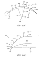
- FIG. 11C is a cross-sectional view depicting the embodiment of FIG. 11B taken over line 3-3.
- corrective portion 122 of anterior surface 102 is substantially spherical having one radius of curvature 106 and posterior surface 103 is also substantially spherical having one radius of curvature 107. Adjustment of these radii 106-107 along with the selection of the appropriate refractive index for regions 402-404 can provide the proper diopter values for each zone to treat a given individual.
- FIG. 11D is an enlarged cross-sectional view of this embodiment lens 100, showing region 411 of FIG. 11C in greater detail.
- lens 100 includes bevel radius 124, edge radius 126 and curved second edge surface portion 128.
- regions 402 and 404 are fabricated from different materials integrally coupled together at interface 403.
- each region 402 and 404 can be fabricated from different microporous hydrogel materials.
- lens 100 is fabricated by first forming a solid polymeric cylindrical core 502, such as that depicted in FIG. 12A , which corresponds to region 402 and has approximately the same diameter as diameter 406 of region 402. This core can then be surrounded by a monomeric solution 503 in a manner similar to that depicted in FIG. 12B .
- Polymeric core 502 is preferably at least slightly soluble in monomeric solution 503.
- Monomeric solution 503 can then be polymerized to form outer polymeric cylindrical region 504 surrounding inner core 502 as depicted in FIG. 12C .
- Outer region 504 preferably corresponds to region 404 and has approximately the same diameter or a slightly larger diameter than diameter 408 of region 404.
- Inner core 502 and outer region 504 together form lens core 506, from which one or more lens can be fabricated, such as, for instance, by separating core 506 into disc-shaped buttons 508 as depicted in FIG. 12D .
- Each individual button can be machined or cut into the desired shape and further processed (e.g., softened, hydrated, etc.) to form an individual lens body 101.
- polymeric core 502 is preferably at least slightly soluble in monomeric solution 503. This is so that solution 503 can dissolve the outer surface of core 502 and become interdispersed and mixed with the dissolved portion of core 502.
- an interface region 505 between cores 502 and 504 can be formed where the different polymers in cores 502 and 504 together form an interpenetrating network. This interface region corresponds to interface region 430 in FIG. 13 below and integrally couples regions 402 and 404 together.
- FIG. 13 is a cross-sectional view of an example embodiment of lens 100 having interface region 430.
- interface region significantly reduces the risk that regions 402 and 404 will separate, such as can be the case when an adhesive is used to join regions 402 and 404.
- interface region 430 can have a refractive index or range of refractive indices between the refractive indices of regions 402 and 404.
- interface region 430 can act as an optical transition between regions 402 and 404 and add a third multifocal region to lens 100. This can eliminate an immediate or sharp transition between the refractive indices of regions 402 and 404 that could result in visual artifacts such as halo or glare.
- the width 420 of interface region 430 can be varied as desired. For instance, to generate a wider interface region 430, monomeric solution 504 can be left in contact with inner core 502 for a longer period of time before polymerization, or, the solubility of inner polymeric core 502 in monomeric solution 504 can be increased. Generally, the wider interface region 430 becomes, the more noticeable region 430 to the subject as a multifocal region.
- lens 100 can be fabricated in any manner and is not limited to the example described with respect to FIGs. 12A-D .
- Other polymerization methods known in the art including, but not limited to, dip coating, spinning, casting, and the polymerization of prepolymers, can be used in the formation of regions 402 and 404.
- each region 402 and 404 is configured with varying levels of permeability.
- region 402 can have a level of permeability to fluid and nutrients that is sufficient to substantially sustain cornea 206
- region 404 can have a permeability to either fluid or fluid and nutrients that is relatively less than region 402, including being entirely impermeable to fluid and nutrients. This allows for the use of more types of materials having a wider range of refractive indices and/or structural characteristics.
- any impermeable region is preferably minimized.
- any circular central region similar to the embodiment of region 402 described with respect to FIG. 11B , that is impermeable to fluid and nutrients is preferably less than about 3 mm in diameter (diameter 406) or about 7.1 square mm.
- lens 100 is not limited to any one total impermeable surface area, the size and surface area of any impermeable region being dependent on the shape of the region and the relative level of permeability of any accompanying regions.
- an example embodiment of lens 100 having many concentric regions arranged in a bullseye fashion where the regions alternate between permeable and impermeable could allow for a total surface area of impermeable regions that is greater than 7.1 square mm.
- FIG. 14A is a top-down view depicting another example embodiment of multifocal lens 100 where corrective portion 122 of anterior surface 102 includes surfaces 602 and 604 having different rates of curvature. Surfaces 602 and 604 have diameters 610 and 612, respectively.
- FIG. 14B is a cross-sectional view of another example embodiment of lens 100 taken along line 4-4 of FIG. 14A .
- surfaces 602 and 604 are each substantially spherical but have different radii of curvature 605 and 606, respectively.
- the abutment between surface 602 and 604 is referenced as interface 603.
- Each surface 602 and 604 can be configured with a different diopter value to correct for separate distances ranges (e.g., near-far, far-near, etc.).
- TABLE 2 depicts example values for three embodiments of a 5.0 millimeter (mm) diameter lens 100 having multiple spherical surfaces 602 and 604 similar to that depicted in FIG. 14B .
- Each of the three embodiments provides for a different degree of correction for relatively far distances (sphere) and relatively near distances (add). These corrective values are shown in the format "sphere diopter/add diopter.” All of these example values are for purposes of illustration only and in no way limit the implantable lens 100 to only these or similar values.
- FIG. 14C is a cross-sectional view of another example embodiment of lens 100 taken along line 4-4 of FIG. 14A .
- surfaces 602 and 604 are each substantially aspherical.
- Surfaces 602 and 604 each have a radius 614 and 616, respectively, measured along central axis 118.
- Radius 616 is measured along central axis 118 from vertex 622 to an imaginary position of surface 604 corresponding to the point where surface 604 would intersect central axis 118 if surface 604 were to extend all the way to central axis 118 as indicated by dashed line 620.
- surface 602 can have any asphericity (Q) and can provide a range of diopter values varying at any rate from apex 105 to interface 603 and can be configured to provide for correction over relatively near distances
- surface 604 can have a range of diopter values varying at any rate from interface 603 to interface 123 and can be configured to provide correction over relatively far distances.
- Q asphericity
- each surface 602 and 604 can have any range of diopter values and provide for correction over any distance.
- TABLE 3 depicts example values for one embodiment of a 5.0 millimeter (mm) diameter lens 100 having multiple aspherical surfaces 602 and 604 similar to that depicted in FIG. 14C .
- Each of the three embodiments provides for a different degree of correction for relatively far distances and relatively near distances. All of these example values are for purposes of illustration only and in no way limit the implantable lens 100 to only these or similar values.
- lens 100 can have one or more transition surfaces at interface 603 that provide for a smoother transition between surfaces 602 and 604, as sharp transitions can stimulate adverse tissue reactions.
- Edge surface 104 and beveled portion 124 are also not depicted in FIGs. 14A-C , but it can be included as desired.
- lens 100 can have any number of multifocal surfaces or refractive regions as desired.
- the multifocal surfaces 602 and 604, substantially spherical or substantially aspherical, can also be arranged in any manner desired including, but not limited to, eccentric, hemispherical, irregular and the like.
Landscapes
- Health & Medical Sciences (AREA)
- Engineering & Computer Science (AREA)
- Ophthalmology & Optometry (AREA)
- Mechanical Engineering (AREA)
- General Health & Medical Sciences (AREA)
- Manufacturing & Machinery (AREA)
- Public Health (AREA)
- Veterinary Medicine (AREA)
- Vascular Medicine (AREA)
- Life Sciences & Earth Sciences (AREA)
- Animal Behavior & Ethology (AREA)
- Biomedical Technology (AREA)
- Transplantation (AREA)
- Heart & Thoracic Surgery (AREA)
- Oral & Maxillofacial Surgery (AREA)
- Cardiology (AREA)
- Physics & Mathematics (AREA)
- General Physics & Mathematics (AREA)
- Optics & Photonics (AREA)
- Prostheses (AREA)
Applications Claiming Priority (3)
| Application Number | Priority Date | Filing Date | Title |
|---|---|---|---|
| US11/106,983 US20050246016A1 (en) | 2004-04-30 | 2005-04-15 | Implantable lenses with modified edge regions |
| EP06750406A EP1874233A4 (en) | 2005-04-15 | 2006-04-13 | IMPLANTABLE LENSES WITH MODIFIED EDGES |
| EP12180173.2A EP2526896B1 (en) | 2005-04-15 | 2006-04-13 | Implantable lenses with modified edge regions |
Related Parent Applications (3)
| Application Number | Title | Priority Date | Filing Date |
|---|---|---|---|
| EP12180173.2A Division-Into EP2526896B1 (en) | 2005-04-15 | 2006-04-13 | Implantable lenses with modified edge regions |
| EP12180173.2A Division EP2526896B1 (en) | 2005-04-15 | 2006-04-13 | Implantable lenses with modified edge regions |
| EP06750406A Division EP1874233A4 (en) | 2005-04-15 | 2006-04-13 | IMPLANTABLE LENSES WITH MODIFIED EDGES |
Publications (1)
| Publication Number | Publication Date |
|---|---|
| EP2979663A1 true EP2979663A1 (en) | 2016-02-03 |
Family
ID=37115804
Family Applications (3)
| Application Number | Title | Priority Date | Filing Date |
|---|---|---|---|
| EP06750406A Withdrawn EP1874233A4 (en) | 2005-04-15 | 2006-04-13 | IMPLANTABLE LENSES WITH MODIFIED EDGES |
| EP15182574.2A Withdrawn EP2979663A1 (en) | 2005-04-15 | 2006-04-13 | Implantable lenses with modified edge regions |
| EP12180173.2A Not-in-force EP2526896B1 (en) | 2005-04-15 | 2006-04-13 | Implantable lenses with modified edge regions |
Family Applications Before (1)
| Application Number | Title | Priority Date | Filing Date |
|---|---|---|---|
| EP06750406A Withdrawn EP1874233A4 (en) | 2005-04-15 | 2006-04-13 | IMPLANTABLE LENSES WITH MODIFIED EDGES |
Family Applications After (1)
| Application Number | Title | Priority Date | Filing Date |
|---|---|---|---|
| EP12180173.2A Not-in-force EP2526896B1 (en) | 2005-04-15 | 2006-04-13 | Implantable lenses with modified edge regions |
Country Status (7)
| Country | Link |
|---|---|
| US (1) | US20050246016A1 (es) |
| EP (3) | EP1874233A4 (es) |
| JP (1) | JP2008541788A (es) |
| AU (1) | AU2006236461A1 (es) |
| CA (1) | CA2604946A1 (es) |
| ES (1) | ES2550488T3 (es) |
| WO (1) | WO2006113595A2 (es) |
Cited By (1)
| Publication number | Priority date | Publication date | Assignee | Title |
|---|---|---|---|---|
| EP3415118A1 (fr) * | 2017-06-16 | 2018-12-19 | Cutting Edge | Implant optique intraoculaire comportant une surface de transition |
Families Citing this family (33)
| Publication number | Priority date | Publication date | Assignee | Title |
|---|---|---|---|---|
| JP3143218B2 (ja) * | 1992-07-28 | 2001-03-07 | 株式会社クボタ | 苗詰め装置 |
| WO2000052516A2 (en) | 1999-03-01 | 2000-09-08 | Boston Innovative Optics, Inc. | System and method for increasing the depth of focus of the human eye |
| US8668735B2 (en) | 2000-09-12 | 2014-03-11 | Revision Optics, Inc. | Corneal implant storage and delivery devices |
| AU2001289038B2 (en) | 2000-09-12 | 2006-05-18 | Revision Optics, Inc. | System for packaging and handling an implant and method of use |
| US8486140B2 (en) * | 2001-01-30 | 2013-07-16 | Timothy R. Willis | Refractive intraocular implant lens and method |
| US20070142912A1 (en) * | 2001-01-30 | 2007-06-21 | Willis Timothy R | Refractive intraocular implant lens and method |
| US8057541B2 (en) | 2006-02-24 | 2011-11-15 | Revision Optics, Inc. | Method of using small diameter intracorneal inlays to treat visual impairment |
| US20080262610A1 (en) * | 2007-04-20 | 2008-10-23 | Alan Lang | Biomechanical design of intracorneal inlays |
| US10835371B2 (en) | 2004-04-30 | 2020-11-17 | Rvo 2.0, Inc. | Small diameter corneal inlay methods |
| US7776086B2 (en) | 2004-04-30 | 2010-08-17 | Revision Optics, Inc. | Aspherical corneal implant |
| US7947076B2 (en) * | 2005-06-03 | 2011-05-24 | Medtronic Xomed, Inc. | Nasal valve treatment method and apparatus |
| CN101495063B (zh) | 2006-01-26 | 2015-04-22 | 韦克福里斯特大学健康科学院 | 用于促进深板层内皮角膜移植术的医用工具和相关的方法 |
| US10555805B2 (en) | 2006-02-24 | 2020-02-11 | Rvo 2.0, Inc. | Anterior corneal shapes and methods of providing the shapes |
| US8162953B2 (en) | 2007-03-28 | 2012-04-24 | Revision Optics, Inc. | Insertion system for corneal implants |
| US9549848B2 (en) | 2007-03-28 | 2017-01-24 | Revision Optics, Inc. | Corneal implant inserters and methods of use |
| US9271828B2 (en) | 2007-03-28 | 2016-03-01 | Revision Optics, Inc. | Corneal implant retaining devices and methods of use |
| CA2720573C (en) | 2008-04-04 | 2019-08-13 | Revision Optics, Inc. | Corneal inlay design and methods of correcting vision |
| US9539143B2 (en) | 2008-04-04 | 2017-01-10 | Revision Optics, Inc. | Methods of correcting vision |
| US8882264B2 (en) * | 2009-09-16 | 2014-11-11 | Indiana University Research And Technology Corporation | Simultaneous vision lenses, design strategies, apparatuses, methods, and systems |
| US8469948B2 (en) | 2010-08-23 | 2013-06-25 | Revision Optics, Inc. | Methods and devices for forming corneal channels |
| RU2619654C2 (ru) | 2011-10-21 | 2017-05-17 | Ревижн Оптикс, Инк. | Устройства для хранения и подачи имплантатов роговицы |
| EP2785296B1 (en) | 2011-12-02 | 2018-06-20 | AcuFocus, Inc. | Ocular mask having selective spectral transmission |
| EP2664300B1 (de) * | 2012-05-14 | 2020-10-28 | Presbia Ireland Limited | Intracorneallinse |
| US9770325B2 (en) * | 2012-06-29 | 2017-09-26 | Abbott Medical Optics Inc. | Reduced glare intraocular lens |
| EP3266415A1 (en) * | 2012-12-06 | 2018-01-10 | Novartis AG | Edge design for reducing photic effects in intraocular lenses |
| ES2472121B1 (es) * | 2012-12-27 | 2015-04-13 | Consejo Superior De Investigaciones Científicas (Csic) | Lente intraocular multifocal refractiva con calidad óptica optimizada en un rango de foco y procedimiento para obtenerla |
| US9204962B2 (en) | 2013-03-13 | 2015-12-08 | Acufocus, Inc. | In situ adjustable optical mask |
| US9427922B2 (en) | 2013-03-14 | 2016-08-30 | Acufocus, Inc. | Process for manufacturing an intraocular lens with an embedded mask |
| WO2016144404A1 (en) | 2015-03-12 | 2016-09-15 | Revision Optics, Inc. | Methods of correcting vision |
| US10695166B2 (en) | 2015-08-14 | 2020-06-30 | Timothy R. Willis | Intraocular lenses (IOLs) and related assemblies and intraocular attachment methods |
| US11690706B2 (en) | 2017-12-13 | 2023-07-04 | Allotex, Inc. | Corneal implant systems and methods |
| EP3781084A1 (en) | 2018-10-24 | 2021-02-24 | AMO Groningen B.V. | Intraocular lenses for reducing the risk of posterior capsule opacification |
| EP3861402A1 (en) * | 2018-12-21 | 2021-08-11 | Alcon Inc. | Multi-curvature edge for ophthalmic lenses |
Citations (3)
| Publication number | Priority date | Publication date | Assignee | Title |
|---|---|---|---|---|
| US5123921A (en) * | 1987-09-14 | 1992-06-23 | Nestle S.A. | Synthetic intracorneal lines and method of manufacture |
| US5196026A (en) * | 1991-09-16 | 1993-03-23 | Chiron Ophthalmics, Inc. | Method of implanting corneal inlay lenses smaller than the optic zone |
| US6875232B2 (en) | 1998-12-23 | 2005-04-05 | Anamed, Inc. | Corneal implant and method of manufacture |
Family Cites Families (103)
| Publication number | Priority date | Publication date | Assignee | Title |
|---|---|---|---|---|
| US3168100A (en) * | 1962-12-07 | 1965-02-02 | Alvido R Rich | Contact lens dipper assembly |
| US3291305A (en) | 1963-07-17 | 1966-12-13 | Eriez Mfg Co | Magnetic separator for mixtures of magnetic and non-magnetic material |
| US3379200A (en) * | 1965-10-24 | 1968-04-23 | Ruth M. Pennell | Lens containtr |
| US3950315A (en) * | 1971-06-11 | 1976-04-13 | E. I. Du Pont De Nemours And Company | Contact lens having an optimum combination of properties |
| US3879076A (en) * | 1973-12-27 | 1975-04-22 | Robert O Barnett | Method and apparatus for applying and removing a soft contact lens |
| US4065816A (en) * | 1975-05-22 | 1978-01-03 | Philip Nicholas Sawyer | Surgical method of using a sterile packaged prosthesis |
| US4071272A (en) * | 1976-09-27 | 1978-01-31 | Drdlik Frank J | Contact lens applicator |
| US4184491A (en) * | 1977-08-31 | 1980-01-22 | The United States Of America As Represented By The Administrator Of The National Aeronautics And Space Administration | Intra-ocular pressure normalization technique and equipment |
| US4194814A (en) * | 1977-11-10 | 1980-03-25 | Bausch & Lomb Incorporated | Transparent opthalmic lens having engraved surface indicia |
| US4257521A (en) * | 1979-11-16 | 1981-03-24 | Stanley Poler | Packaging means for an intraocular lens |
| US4326306A (en) * | 1980-12-16 | 1982-04-27 | Lynell Medical Technology, Inc. | Intraocular lens and manipulating tool therefor |
| US4428746A (en) * | 1981-07-29 | 1984-01-31 | Antonio Mendez | Glaucoma treatment device |
| US5188125A (en) * | 1982-01-04 | 1993-02-23 | Keravision, Inc. | Method for corneal curvature adjustment |
| US4490860A (en) * | 1982-01-18 | 1985-01-01 | Ioptex Inc. | Intraocular lens apparatus and method for implantation of same |
| US4423809A (en) * | 1982-02-05 | 1984-01-03 | Staar Surgical Company, Inc. | Packaging system for intraocular lens structures |
| US4504982A (en) * | 1982-08-05 | 1985-03-19 | Optical Radiation Corporation | Aspheric intraocular lens |
| US4580882A (en) * | 1983-04-21 | 1986-04-08 | Benjamin Nuchman | Continuously variable contact lens |
| US4565198A (en) * | 1983-12-27 | 1986-01-21 | Barnes-Hind, Inc. | Method for altering the curvature of the cornea |
| US4640595A (en) * | 1984-05-02 | 1987-02-03 | David Volk | Aspheric contact lens |
| US4646720A (en) * | 1985-03-12 | 1987-03-03 | Peyman Gholam A | Optical assembly permanently attached to the cornea |
| US4726367A (en) * | 1985-08-19 | 1988-02-23 | Shoemaker David W | Surgical instrument for implanting an intraocular lens |
| GB2185124B (en) * | 1986-01-03 | 1989-10-25 | Choyce David P | Intra-corneal implant |
| US5114627A (en) * | 1986-10-16 | 1992-05-19 | Cbs Lens | Method for producing a collagen hydrogel |
| US4919130A (en) * | 1986-11-07 | 1990-04-24 | Nestle S.A. | Tool for inserting compressible intraocular lenses into the eye and method |
| US4897981A (en) * | 1986-12-24 | 1990-02-06 | Alcon Laboratories, Inc. | Method of packaging intraocular lenses and contact lenses |
| US4806382A (en) * | 1987-04-10 | 1989-02-21 | University Of Florida | Ocular implants and methods for their manufacture |
| US5270744A (en) * | 1987-06-01 | 1993-12-14 | Valdemar Portney | Multifocal ophthalmic lens |
| US5282851A (en) * | 1987-07-07 | 1994-02-01 | Jacob Labarre Jean | Intraocular prostheses |
| US4798609A (en) * | 1987-08-24 | 1989-01-17 | Grendahl Dennis T | Radially segmented zone of focus artificial lens |
| US5108428A (en) * | 1988-03-02 | 1992-04-28 | Minnesota Mining And Manufacturing Company | Corneal implants and manufacture and use thereof |
| US5192317A (en) * | 1988-07-26 | 1993-03-09 | Irvin Kalb | Multi focal intra-ocular lens |
| US4911715A (en) * | 1989-06-05 | 1990-03-27 | Kelman Charles D | Overlapping two piece intraocular lens |
| US5591185A (en) * | 1989-12-14 | 1997-01-07 | Corneal Contouring Development L.L.C. | Method and apparatus for reprofiling or smoothing the anterior or stromal cornea by scraping |
| US5092837A (en) * | 1989-12-20 | 1992-03-03 | Robert Ritch | Method for the treatment of glaucoma |
| US5098444A (en) * | 1990-03-16 | 1992-03-24 | Feaster Fred T | Epiphakic intraocular lens and process of implantation |
| US5180362A (en) * | 1990-04-03 | 1993-01-19 | Worst J G F | Gonio seton |
| US5181053A (en) * | 1990-05-10 | 1993-01-19 | Contact Lens Corporation Of America | Multi-focal contact lens |
| US5397300A (en) * | 1990-05-31 | 1995-03-14 | Iovision, Inc. | Glaucoma implant |
| US5178604A (en) * | 1990-05-31 | 1993-01-12 | Iovision, Inc. | Glaucoma implant |
| JPH06505186A (ja) * | 1991-02-11 | 1994-06-16 | オマーヤ,アユブ ケー. | 脊髄液駆動式人工器官 |
| US5300020A (en) * | 1991-05-31 | 1994-04-05 | Medflex Corporation | Surgically implantable device for glaucoma relief |
| US5512220A (en) * | 1991-07-10 | 1996-04-30 | Johnson & Johnson Vision Products, Inc. | Method of making a clear axis, segmented multifocal ophthalmic lens |
| CA2127109A1 (en) * | 1992-01-02 | 1993-07-08 | Graham D. Barrett | Corneal ring inlay and methods of use |
| US5190552A (en) * | 1992-02-04 | 1993-03-02 | Kelman Charles D | Slotted tube injector for an intraocular lens |
| US5344448A (en) * | 1992-02-11 | 1994-09-06 | Schneider Richard T | Multi-focal intra-ocular implant |
| AU650156B2 (en) * | 1992-08-05 | 1994-06-09 | Lions Eye Institute Limited | Keratoprosthesis and method of producing the same |
| ES2133411T3 (es) * | 1992-08-07 | 1999-09-16 | Keravision Inc | Anillo corneal intraestromal. |
| US5405384A (en) * | 1992-09-03 | 1995-04-11 | Keravision, Inc. | Astigmatic correcting intrastromal corneal ring |
| US5755786A (en) * | 1992-09-28 | 1998-05-26 | Iolab Corporation | Ophthalmic lens with reduced edge glare |
| US5616148A (en) * | 1992-09-30 | 1997-04-01 | Staar Surgical Company, Inc. | Transverse hinged deformable intraocular lens injecting apparatus |
| US5860984A (en) * | 1992-09-30 | 1999-01-19 | Staar Surgical Company, Inc. | Spring biased deformable intraocular injecting apparatus |
| US5620450A (en) * | 1992-09-30 | 1997-04-15 | Staar Surgical Company, Inc. | Transverse hinged deformable intraocular lens injecting apparatus |
| US6712848B1 (en) * | 1992-09-30 | 2004-03-30 | Staar Surgical Company, Inc. | Deformable intraocular lens injecting apparatus with transverse hinged lens cartridge |
| US5872613A (en) * | 1992-11-23 | 1999-02-16 | Innotech, Inc. | Method of manufacturing contact lenses |
| US5406341A (en) * | 1992-11-23 | 1995-04-11 | Innotech, Inc. | Toric single vision, spherical or aspheric bifocal, multifocal or progressive contact lenses and method of manufacturing |
| US5653715A (en) * | 1993-03-09 | 1997-08-05 | Chiron Vision Corporation | Apparatus for preparing an intraocular lens for insertion |
| US5493350A (en) * | 1993-03-31 | 1996-02-20 | Seidner; Leonard | Multipocal contact lens and method for preparing |
| US5489301A (en) * | 1993-09-03 | 1996-02-06 | Barber; John C. | Corneal prosthesis |
| US5502518A (en) * | 1993-09-09 | 1996-03-26 | Scient Optics Inc | Asymmetric aspheric contact lens |
| US6197019B1 (en) * | 1994-04-25 | 2001-03-06 | Gholam A. Peyman | Universal implant blank for modifying corneal curvature and methods of modifying corneal curvature therewith |
| US5715031A (en) * | 1995-05-04 | 1998-02-03 | Johnson & Johnson Vision Products, Inc. | Concentric aspheric multifocal lens designs |
| US6175754B1 (en) * | 1995-06-07 | 2001-01-16 | Keravision, Inc. | Method and apparatus for measuring corneal incisions |
| US5968065A (en) * | 1995-07-13 | 1999-10-19 | Origin Medsystems, Inc. | Tissue separation cannula |
| US6221067B1 (en) * | 1995-10-20 | 2001-04-24 | Gholam A. Peyman | Corneal modification via implantation |
| US5964748A (en) * | 1995-10-20 | 1999-10-12 | Peyman; Gholam A. | Intrastromal corneal modification |
| US5722971A (en) * | 1995-10-20 | 1998-03-03 | Peyman; Gholam A. | Intrastromal corneal modification |
| US6203538B1 (en) * | 1995-11-03 | 2001-03-20 | Gholam A. Peyman | Intrastromal corneal modification |
| US5728155A (en) * | 1996-01-22 | 1998-03-17 | Quantum Solutions, Inc. | Adjustable intraocular lens |
| US5722948A (en) * | 1996-02-14 | 1998-03-03 | Gross; Fredric J. | Covering for an ocular device |
| FR2746000B1 (fr) * | 1996-03-14 | 1998-06-12 | Implant intraoculaire souple et ensemble de tels implants | |
| US5855604A (en) * | 1996-12-09 | 1999-01-05 | Microoptix, Llc | Method and apparatus for adjusting corneal curvature using a solid filled corneal ring |
| US5876439A (en) * | 1996-12-09 | 1999-03-02 | Micooptix, Llc | Method and appartus for adjusting corneal curvature using a fluid-filled corneal ring |
| US5873889A (en) * | 1997-08-08 | 1999-02-23 | Origin Medsystems, Inc. | Tissue separation cannula with dissection probe and method |
| US6033395A (en) * | 1997-11-03 | 2000-03-07 | Peyman; Gholam A. | System and method for modifying a live cornea via laser ablation and mechanical erosion |
| US6050999A (en) * | 1997-12-18 | 2000-04-18 | Keravision, Inc. | Corneal implant introducer and method of use |
| AU731944B2 (en) * | 1997-12-29 | 2001-04-05 | Duckworth & Kent Limited | Injectors for intraocular lenses |
| US6206919B1 (en) * | 1998-01-14 | 2001-03-27 | Joseph Y. Lee | Method and apparatus to correct refractive errors using adjustable corneal arcuate segments |
| US6024448A (en) * | 1998-03-31 | 2000-02-15 | Johnson & Johnson Vision Products, Inc. | Contact lenses bearing identifying marks |
| JP4023902B2 (ja) * | 1998-04-10 | 2007-12-19 | 株式会社メニコン | トーリック・マルチフォーカルレンズ |
| US6371960B2 (en) * | 1998-05-19 | 2002-04-16 | Bausch & Lomb Surgical, Inc. | Device for inserting a flexible intraocular lens |
| US6183513B1 (en) * | 1998-06-05 | 2001-02-06 | Bausch & Lomb Surgical, Inc. | Intraocular lens packaging system, method of producing, and method of using |
| US6171324B1 (en) * | 1998-09-30 | 2001-01-09 | Becton, Dickinson And Company | Marker for corneal incision |
| US6197057B1 (en) * | 1998-10-27 | 2001-03-06 | Gholam A. Peyman | Lens conversion system for teledioptic or difractive configurations |
| US6210005B1 (en) * | 1999-02-04 | 2001-04-03 | Valdemar Portney | Multifocal ophthalmic lens with reduced halo size |
| US6197058B1 (en) * | 1999-03-22 | 2001-03-06 | Valdemar Portney | Corrective intraocular lens system and intraocular lenses and lens handling device therefor |
| NZ514935A (en) * | 1999-04-26 | 2003-10-31 | Gmp Vision Solutions Inc | Shunt device and method for treating glaucoma |
| US6511178B1 (en) * | 1999-07-19 | 2003-01-28 | Johnson & Johnson Vision Care, Inc. | Multifocal ophthalmic lenses and processes for their production |
| US6599317B1 (en) * | 1999-09-17 | 2003-07-29 | Advanced Medical Optics, Inc. | Intraocular lens with a translational zone |
| US6645246B1 (en) * | 1999-09-17 | 2003-11-11 | Advanced Medical Optics, Inc. | Intraocular lens with surrounded lens zone |
| US6364483B1 (en) * | 2000-02-22 | 2002-04-02 | Holo Or Ltd. | Simultaneous multifocal contact lens and method of utilizing same for treating visual disorders |
| US6474814B1 (en) * | 2000-09-08 | 2002-11-05 | Florida Optical Engineering, Inc | Multifocal ophthalmic lens with induced aperture |
| US6589280B1 (en) * | 2001-05-11 | 2003-07-08 | Jeffrey E. Koziol | Method for producing a multifocal corneal surface using intracorneal microscopic lenses |
| WO2002100299A1 (en) * | 2001-06-13 | 2002-12-19 | The Lions Eye Institute Of Western Australia Incorporated | Improved keratoprosthesis |
| US20030014042A1 (en) * | 2001-07-13 | 2003-01-16 | Tibor Juhasz | Method of creating stromal pockets for corneal implants |
| US6537283B2 (en) * | 2001-08-17 | 2003-03-25 | Alcon, Inc. | Intraocular lens shipping case and injection cartridge |
| US6623522B2 (en) * | 2001-11-07 | 2003-09-23 | Alok Nigam | Myopic corneal ring with central accommodating portion |
| US6855163B2 (en) * | 2002-07-19 | 2005-02-15 | Minu, Llc | Gradual correction of corneal refractive error using multiple inlays |
| US20040019379A1 (en) * | 2002-07-25 | 2004-01-29 | Advanced Medical Optics, Inc. | Intracorneal lens with flow enhancement area for increased nutrient transport |
| US20040034413A1 (en) * | 2002-08-13 | 2004-02-19 | Christensen James M. | Hydrogel corneal inlay |
| US7018409B2 (en) * | 2002-09-13 | 2006-03-28 | Advanced Medical Optics, Inc. | Accommodating intraocular lens assembly with aspheric optic design |
| CA2498717A1 (en) * | 2002-09-13 | 2004-03-25 | Ocular Sciences, Inc. | Devices and methods for improving vision |
| US6709103B1 (en) * | 2002-10-31 | 2004-03-23 | Johnson & Johnson Vision Care, Inc. | Methods for designing multifocal ophthalmic lenses |
| US20060020267A1 (en) * | 2004-07-15 | 2006-01-26 | Marmo J C | Intrastromal devices and methods for improving vision |
-
2005
- 2005-04-15 US US11/106,983 patent/US20050246016A1/en not_active Abandoned
-
2006
- 2006-04-13 ES ES12180173.2T patent/ES2550488T3/es active Active
- 2006-04-13 EP EP06750406A patent/EP1874233A4/en not_active Withdrawn
- 2006-04-13 EP EP15182574.2A patent/EP2979663A1/en not_active Withdrawn
- 2006-04-13 JP JP2008506804A patent/JP2008541788A/ja active Pending
- 2006-04-13 CA CA002604946A patent/CA2604946A1/en not_active Abandoned
- 2006-04-13 WO PCT/US2006/014356 patent/WO2006113595A2/en active Application Filing
- 2006-04-13 EP EP12180173.2A patent/EP2526896B1/en not_active Not-in-force
- 2006-04-13 AU AU2006236461A patent/AU2006236461A1/en not_active Abandoned
Patent Citations (3)
| Publication number | Priority date | Publication date | Assignee | Title |
|---|---|---|---|---|
| US5123921A (en) * | 1987-09-14 | 1992-06-23 | Nestle S.A. | Synthetic intracorneal lines and method of manufacture |
| US5196026A (en) * | 1991-09-16 | 1993-03-23 | Chiron Ophthalmics, Inc. | Method of implanting corneal inlay lenses smaller than the optic zone |
| US6875232B2 (en) | 1998-12-23 | 2005-04-05 | Anamed, Inc. | Corneal implant and method of manufacture |
Cited By (2)
| Publication number | Priority date | Publication date | Assignee | Title |
|---|---|---|---|---|
| EP3415118A1 (fr) * | 2017-06-16 | 2018-12-19 | Cutting Edge | Implant optique intraoculaire comportant une surface de transition |
| FR3067590A1 (fr) * | 2017-06-16 | 2018-12-21 | Cutting Edge | Implant optique intraoculaire comportant une surface de transition |
Also Published As
| Publication number | Publication date |
|---|---|
| AU2006236461A1 (en) | 2006-10-26 |
| EP1874233A2 (en) | 2008-01-09 |
| EP2526896B1 (en) | 2015-10-07 |
| EP2526896A1 (en) | 2012-11-28 |
| CA2604946A1 (en) | 2006-10-26 |
| US20050246016A1 (en) | 2005-11-03 |
| WO2006113595A2 (en) | 2006-10-26 |
| ES2550488T3 (es) | 2015-11-10 |
| JP2008541788A (ja) | 2008-11-27 |
| WO2006113595A3 (en) | 2009-04-30 |
| EP1874233A4 (en) | 2012-11-14 |
Similar Documents
| Publication | Publication Date | Title |
|---|---|---|
| EP2526896B1 (en) | Implantable lenses with modified edge regions | |
| US20130231739A1 (en) | Small Diameter Corneal Inlays | |
| US6875232B2 (en) | Corneal implant and method of manufacture | |
| US6626941B2 (en) | Corneal implant and method of manufacture | |
| US11547552B2 (en) | Small diameter corneal inlays | |
| AU2004201751B2 (en) | Corneal implant and method of manufacture | |
| EP1334398B1 (en) | Contact lens and methods of manufacture | |
| EP2111822A2 (en) | Intraocular lens with a toric optic | |
| WO2005107648A2 (en) | Aspherical corneal implant | |
| RU2783105C1 (ru) | Фотохромная мягкая контактная линза с косметическими соображениями и соображениями эффективности | |
| CA2608175C (en) | Corneal implant and method of manufacture | |
| CA2595034C (en) | Corneal implant | |
| Koppen | Specialty Lenses for Keratoconus |
Legal Events
| Date | Code | Title | Description |
|---|---|---|---|
| PUAI | Public reference made under article 153(3) epc to a published international application that has entered the european phase |
Free format text: ORIGINAL CODE: 0009012 |
|
| AC | Divisional application: reference to earlier application |
Ref document number: 2526896 Country of ref document: EP Kind code of ref document: P Ref document number: 1874233 Country of ref document: EP Kind code of ref document: P |
|
| AK | Designated contracting states |
Kind code of ref document: A1 Designated state(s): AT BE BG CH CY CZ DE DK EE ES FI FR GB GR HU IE IS IT LI LT LU LV MC NL PL PT RO SE SI SK TR |
|
| 17P | Request for examination filed |
Effective date: 20160802 |
|
| RBV | Designated contracting states (corrected) |
Designated state(s): AT BE BG CH CY CZ DE DK EE ES FI FR GB GR HU IE IS IT LI LT LU LV MC NL PL PT RO SE SI SK TR |
|
| STAA | Information on the status of an ep patent application or granted ep patent |
Free format text: STATUS: EXAMINATION IS IN PROGRESS |
|
| 17Q | First examination report despatched |
Effective date: 20190114 |
|
| STAA | Information on the status of an ep patent application or granted ep patent |
Free format text: STATUS: THE APPLICATION IS DEEMED TO BE WITHDRAWN |
|
| 18D | Application deemed to be withdrawn |
Effective date: 20190725 |