EP2979609A1 - Manipulator, manipulator system, and manipulator control method - Google Patents
Manipulator, manipulator system, and manipulator control method Download PDFInfo
- Publication number
- EP2979609A1 EP2979609A1 EP14772996.6A EP14772996A EP2979609A1 EP 2979609 A1 EP2979609 A1 EP 2979609A1 EP 14772996 A EP14772996 A EP 14772996A EP 2979609 A1 EP2979609 A1 EP 2979609A1
- Authority
- EP
- European Patent Office
- Prior art keywords
- unit
- manipulator
- extending
- retracting
- insert
- Prior art date
- Legal status (The legal status is an assumption and is not a legal conclusion. Google has not performed a legal analysis and makes no representation as to the accuracy of the status listed.)
- Withdrawn
Links
Images









Classifications
-
- A—HUMAN NECESSITIES
- A61—MEDICAL OR VETERINARY SCIENCE; HYGIENE
- A61B—DIAGNOSIS; SURGERY; IDENTIFICATION
- A61B1/00—Instruments for performing medical examinations of the interior of cavities or tubes of the body by visual or photographical inspection, e.g. endoscopes; Illuminating arrangements therefor
- A61B1/00147—Holding or positioning arrangements
- A61B1/0016—Holding or positioning arrangements using motor drive units
-
- A—HUMAN NECESSITIES
- A61—MEDICAL OR VETERINARY SCIENCE; HYGIENE
- A61B—DIAGNOSIS; SURGERY; IDENTIFICATION
- A61B1/00—Instruments for performing medical examinations of the interior of cavities or tubes of the body by visual or photographical inspection, e.g. endoscopes; Illuminating arrangements therefor
- A61B1/00002—Operational features of endoscopes
- A61B1/00004—Operational features of endoscopes characterised by electronic signal processing
- A61B1/00009—Operational features of endoscopes characterised by electronic signal processing of image signals during a use of endoscope
- A61B1/000094—Operational features of endoscopes characterised by electronic signal processing of image signals during a use of endoscope extracting biological structures
-
- A—HUMAN NECESSITIES
- A61—MEDICAL OR VETERINARY SCIENCE; HYGIENE
- A61B—DIAGNOSIS; SURGERY; IDENTIFICATION
- A61B1/00—Instruments for performing medical examinations of the interior of cavities or tubes of the body by visual or photographical inspection, e.g. endoscopes; Illuminating arrangements therefor
- A61B1/00002—Operational features of endoscopes
- A61B1/00039—Operational features of endoscopes provided with input arrangements for the user
- A61B1/00042—Operational features of endoscopes provided with input arrangements for the user for mechanical operation
-
- A—HUMAN NECESSITIES
- A61—MEDICAL OR VETERINARY SCIENCE; HYGIENE
- A61B—DIAGNOSIS; SURGERY; IDENTIFICATION
- A61B1/00—Instruments for performing medical examinations of the interior of cavities or tubes of the body by visual or photographical inspection, e.g. endoscopes; Illuminating arrangements therefor
- A61B1/00064—Constructional details of the endoscope body
- A61B1/00066—Proximal part of endoscope body, e.g. handles
-
- A—HUMAN NECESSITIES
- A61—MEDICAL OR VETERINARY SCIENCE; HYGIENE
- A61B—DIAGNOSIS; SURGERY; IDENTIFICATION
- A61B1/00—Instruments for performing medical examinations of the interior of cavities or tubes of the body by visual or photographical inspection, e.g. endoscopes; Illuminating arrangements therefor
- A61B1/00064—Constructional details of the endoscope body
- A61B1/00071—Insertion part of the endoscope body
-
- A—HUMAN NECESSITIES
- A61—MEDICAL OR VETERINARY SCIENCE; HYGIENE
- A61B—DIAGNOSIS; SURGERY; IDENTIFICATION
- A61B1/00—Instruments for performing medical examinations of the interior of cavities or tubes of the body by visual or photographical inspection, e.g. endoscopes; Illuminating arrangements therefor
- A61B1/00163—Optical arrangements
- A61B1/00174—Optical arrangements characterised by the viewing angles
- A61B1/00179—Optical arrangements characterised by the viewing angles for off-axis viewing
-
- A—HUMAN NECESSITIES
- A61—MEDICAL OR VETERINARY SCIENCE; HYGIENE
- A61B—DIAGNOSIS; SURGERY; IDENTIFICATION
- A61B1/00—Instruments for performing medical examinations of the interior of cavities or tubes of the body by visual or photographical inspection, e.g. endoscopes; Illuminating arrangements therefor
- A61B1/00163—Optical arrangements
- A61B1/00174—Optical arrangements characterised by the viewing angles
- A61B1/00183—Optical arrangements characterised by the viewing angles for variable viewing angles
-
- A—HUMAN NECESSITIES
- A61—MEDICAL OR VETERINARY SCIENCE; HYGIENE
- A61B—DIAGNOSIS; SURGERY; IDENTIFICATION
- A61B34/00—Computer-aided surgery; Manipulators or robots specially adapted for use in surgery
- A61B34/30—Surgical robots
-
- G—PHYSICS
- G02—OPTICS
- G02B—OPTICAL ELEMENTS, SYSTEMS OR APPARATUS
- G02B23/00—Telescopes, e.g. binoculars; Periscopes; Instruments for viewing the inside of hollow bodies; Viewfinders; Optical aiming or sighting devices
- G02B23/24—Instruments or systems for viewing the inside of hollow bodies, e.g. fibrescopes
- G02B23/2476—Non-optical details, e.g. housings, mountings, supports
-
- G—PHYSICS
- G02—OPTICS
- G02B—OPTICAL ELEMENTS, SYSTEMS OR APPARATUS
- G02B23/00—Telescopes, e.g. binoculars; Periscopes; Instruments for viewing the inside of hollow bodies; Viewfinders; Optical aiming or sighting devices
- G02B23/24—Instruments or systems for viewing the inside of hollow bodies, e.g. fibrescopes
- G02B23/2476—Non-optical details, e.g. housings, mountings, supports
- G02B23/2484—Arrangements in relation to a camera or imaging device
-
- A—HUMAN NECESSITIES
- A61—MEDICAL OR VETERINARY SCIENCE; HYGIENE
- A61B—DIAGNOSIS; SURGERY; IDENTIFICATION
- A61B17/00—Surgical instruments, devices or methods
- A61B17/28—Surgical forceps
- A61B17/29—Forceps for use in minimally invasive surgery
-
- A—HUMAN NECESSITIES
- A61—MEDICAL OR VETERINARY SCIENCE; HYGIENE
- A61B—DIAGNOSIS; SURGERY; IDENTIFICATION
- A61B34/00—Computer-aided surgery; Manipulators or robots specially adapted for use in surgery
- A61B34/30—Surgical robots
- A61B2034/302—Surgical robots specifically adapted for manipulations within body cavities, e.g. within abdominal or thoracic cavities
Definitions
- the present invention relates to a manipulator designed to be inserted into the body cavity, a manipulator system, and a manipulator control method.
- a manipulator having an elongate insert inserted in the body cavity has been extensively used, in which a bendable portion at the front end of the insert is pulled and bent by a wire or the like for the purpose of observing organs in the body cavity and giving medical treatments to them.
- Patent Publication 1 JP(A) 2005-74148 discloses a technique including an extending/retracting member located movably in a bendable portion of an insert via a guide wherein movement of the extending/retracting member is adjusted such that it advances toward or retreats from the bendable portion of the insert whereby the bendable portion of the insert is positioned selectively, substantially linearly or in a bendable manner.
- Patent Publication 1 JP(A) 2005-74148
- the invention has for its object to provide a manipulator, a manipulator system and a manipulator control method, which may relieve the operator of such un-comfortableness.
- the invention provides a manipulator including an insert unit capable of being inserted through the body cavity, an operating unit for operating the insert unit, an extending/retracting unit for moving the insert unit forward or backward, a drive unit for driving the insert unit and the extending/retracting unit, and a control unit for controlling the drive unit in association with operation of the operating unit, characterized in that the insert unit includes a bendable portion, and the drive unit includes a bending movement driving portion for generating driving force for bending the bendable portion and an extension/retraction driving portion for generating driving force for moving the extending/retracting unit forward or backward, characterized in that the control unit controls the extension/retraction driving portion and the bending movement driving portion in association with operation of the operating unit.
- manipulator manipulator system and manipulator control method according to one embodiment of the invention, it is possible to relieve less experienced operators of un-comfortableness.
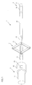
- Fig. 1 is a diagrammatic view of the manipulator 1 according to one embodiment of the invention.
- the manipulator 1 comprises an insert unit 2, an operating unit 3, and an extending/retracting unit 4.
- the manipulator 1 includes the insert unit 2 on a front-end (distal end) side and the operating unit 3 on a base-end (proximal end) side, and includes the extending/retracting unit 4 on the operating unit 3 side of the insert unit 2.
- the insert unit 2 includes a front-end portion 21, a bendable portion 22, and a power transmission portion 23.
- the operating unit 3 includes a grip 31, a main body 32, a mode selection instruction portion 33, and a coupling 34.
- the extending/retracting unit 4 includes a link portion 41 and a guide portion 42.
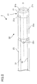
- Fig. 2 is an enlarged view of the insert unit 2 of the manipulator 1 according to one embodiment of the invention.
- the insert unit 2 to be inserted through the body cavity includes the front-end portion 21, bendable portion 22 and power transmission portion 23 in order from the front-end side.
- the front-end portion 21 includes a cylindrical, hard main body 21a attached to the front end of the manipulator 1. Taking an endoscope as an example, the front-end portion 21 may have in it an imaging portion 21b for taking images of the site of interest, a lighting portion 21c for illuminating the site of interest, etc. A treatment tool (not shown) for giving treatment to the site of interest or the like may be built in the front-end portion 21.
- the bendable portion 22 includes a substantially cylindrical block 22a to which the front-end portion 21 is attached, and a joint 22b for making a rotatable coupling between the block 22a and the power transmission portion 23 within a given angle range.
- the power transmission portion 23 is an elongate, substantially cylindrical shaft or like other member coupled to the front-end side to the bendable portion 22 by way of the joint 22b and on the base-end side to the extending/ retracting unit 4.
- the front-end portion 21 is fixedly provided with first and second wires 51 and 52 for activation of the bendable portion.
- the first and second wires 51 and 52 for activation of the bendable portion are fixedly provided in opposite positions with a plane including the joint 22b in between. As an example, those positions are preferably symmetrical with respect to the center axis C of the cylindrical front-end portion 21.
- the first and second wires 51 and 52 for activation of the bendable portion are taken up or fed out by an actuator (not shown) or the like within the main body 32 of the operating unit shown in Fig. 1 .
- the structure of the insert unit 2 is not limited to this; so it may be modified in various ways.
- a plurality of blocks 22a and a plurality of joints 22b may be alternately combined into a bent state having a higher degree of freedom.
- a set of adjoining block 22a and joint 22b in a plurality of block 22a/joints 22b combinations are rotated for each 90° about the axis of the bendable portion 22 in a straightly extended state or the center axis C of the power transmission portion 23 such that the insert unit 2 is three dimensionally movable.
- Fig. 3 is an enlarged view of the operating unit 3 according to one embodiment of the invention.
- the operating unit 3 includes a grip 31 of which the operator takes a grip, a main body 32 of the operating unit 3 having a built-in drive part 6 for operating movement or the like of the insert unit 2 provided on the extending/retracting unit 4 side of the grip 31 and extending/retracting unit 4 as described later, a mode selection instruction portion 33 that can be forced in the main body 32, and a coupling 34 coupled to the extending/ retracting unit 4.
- the main body 32 of the operating unit has the built-in drive unit 6 including a motor, a pulley and so on as described later.
- the main body 32 of the operating unit takes up or feeds out the first and second wires 51 and 52 for activation of the bendable portion thereby bending the bendable portion 22 of the insert unit 2 shown in Fig. 1 .
- the main body 32 of the operating unit also takes up and feeds out a link activation wire 53 thereby causing extension and retraction of a link 41 of the extending/retracting unit 4 shown in Fig. 1 .
- the mode selection instruction portion 33 comprises a push switch and so on. Usually, when the push switch or the like is not pushed down, the mode selection instruction portion 33 is set in a manual mode as the first mode, and as the push switch or the like is pushed down, the mode selection instruction part 33 issues an instruction to change the manual mode over to an electrically operated mode as the second mode.
- the coupling 34 has the first and second wires 51 and 52 for activation of the bendable portion and the link activation wire 53 inserted through it, and is coupled to the extending/ retracting unit 4 shown in Fig. 1 .
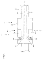
- Fig. 4 is a schematic view of the drive unit 6 according to one embodiment of the invention.
- the drive unit 6 includes a portion 61 for driving bending movement, and a portion 62 for driving extension/retraction (not shown).
- the driving portions 61 and 62 may be of the same construction; so the driving portion 61 for driving bending movement is here explained.
- the driving portion 61 for driving bending movement includes a motor 61a, a driving pulley 61b, and a driven or follower pulley 61c.
- first and second wires 51 and 52 for activation of the bendable portion are firmly fixed to the main body 21a of the front-end portion 21 shown in Fig. 2 , and the other ends of the first and second wires 51 and 52 are firmly fixed to the driving pulley 61b.
- the first and second wires 51 and 52 for activation of the bendable portion are wound around the driven pulley 61c.
- the driving pulley 61b is mounted on the rotary shaft of the motor 61a to take up and feed out the first and second wires 51 and 52 at the driven pulley 61b in association with the rotation of the motor 61a. In turn, the rotational driving force of the motor 61a is transmitted to the main body 21a of the front-end portion 21.
- two portions 61 for driving bending movement are symmetrically provided with respect to the center line C of the coupling 34 for the purpose of explaining movement in a two-dimensional plane; however, it is to be understood that the invention is not always limited to two portions 61; there may be one or two or more portions 61 provided depending on the direction of rotation of the joint 22b.
- one driving portion 61 for driving bending movement is provided in combination with one wire for activation of the bendable portion
- one wire for activation of the bendable portion may be looped around the driving pulley of the portion 61 for driving bending movement and the pulley mounted on the joint 22b.
- the driving pulley is rotated by the rotational driving of one motor so that the block 22a can be bent vertically by way of the wire for activation of the bendable portion and the pulley.
- additional portions 61 for driving bending movement may be provided before and after the drawing sheet.
- the structure of the portion 61 for driving bending movement is not always limited to the aforesaid one; it may be modified in various ways.
- the respective joints 22b may be individually operated.
- the individually operable structure is preferable because there is an increased degree of freedom in the posture of the bendable portion 22.
- the portion 61 for driving bending movement is located within the operating unit 3 in the example shown in Fig. 4 , it is to be noted that it may be provided separately from the operating unit 3. That is, while the insert unit 2 is positioned near the patient, the operating unit 3 may be operated by the operator from a remote position.
- Fig. 5 is an enlarged view of the extending/ retracting unit 4 according to one embodiment of the invention.
- the extending/retracting unit 4 includes a link 41 coupled on one side to the operating unit 3 and on the other side to the insert unit 2, and a guide 42 for guiding operation of the link 41.
- the link 41 includes a first protrusion 41a that is mounted on the coupling 34 and guided by the guide 42, a first arm 41b that is rotatably mounted on the first protrusion 41a, a second protrusion 41c that is attached to the power transmission portion 23 and guided by the guide 42, a second arm 41d that is rotatably mounted on the second protrusion 41c, and a connecting portion 41e for making a connection between the first and second arms 41b and 41d.
- the guide 42 is an elongate member that is fixed on one side to the coupling 34 and on the other side to the power transmission portion 23.
- the guide 42 is provided with a long opening 42a for receiving the first and second protrusions 41a and 41c.
- the first and second protrusions 41a and 41c are movable along the elongate opening 42a.
- first arms 41b, two second arms 41d and two connecting portions 41e are provided with the guide 42 between them.
- the link activation wire 53 is wound around at least one connecting portion 41e, and the main body 32 of the operating unit takes up the link activation wire 53 thereby extending and retracting the link 41 having a so-called pantograph structure.
- first and second arms 41b and 41d There is a cavity inside the first and second arms 41b and 41d, through which the first and second wires 51 and 52 for activation of the bendable portion, the link activation wire 53, wirings for electronic components, etc. are passed.
- multiple links 41 and multiple guides 42 may be provided to make the extending/ retracting distance long.
- Movement of the manipulator 1 is now explained. First, one example of bending movement is explained.
- Fig. 6 is a schematic view of one example of operation of the insert unit 2 according to one embodiment of the invention.
- the manipulator 1 according to one embodiment of the invention actually operates in a three-dimensional space; for the sake of an easy understanding of the invention, however, operation of the manipulator 1 in a two-dimensional plane is here explained with reference to a schematic view like Fig. 6 .
- the front-end portion 21, bendable portion 22, and power transmission portion 23 are in a linear state as shown in Fig. 1 .
- the drive unit 6 As the drive unit 6 is activated by operation of the operating unit 3 shown in Fig. 3 , it causes the front-end portion 21 and block 22a to be pulled by the first or second wire 51 or 52 for activation of the bendable portion so that the front-end portion 21 and bendable portion 22 bend at the joint 22b with respect to the power transmission portion 23.
- Fig. 6A shows that the first wire 51 for activation of the bendable portion is being pulled by the drive unit 6 shown in Fig. 4 ; the front-end portion 21 and block 22a are rotated in a direction indicated by an arrow A. It is here preferable that the second wire 52 for activation of the bendable portion is fed out.
- Fig. 6B shows that the second wire 52 for activation of the bendable part is being pulled by the drive unit 6 shown in Fig. 4 ; the front-end portion 21 and block 22a are rotated in a direction indicated by an arrow B. It is here preferable that the first wire 51 for activation of the bendable portion is fed out.
- the respective joints 22b may be individually actuated. Such individual actuation is preferable because there is an increased degree of freedom in posture.
- the main body 32 of the operating unit may be provided separately from the operating unit 3: the main body 32 may be positioned near the patient while the operating unit 3 may be remote controlled from a remote position.
- Fig. 7 is a schematic view of an example of movement of the extending/retracting unit 4 according to this embodiment of the invention.
- a pantograph mechanism is used as an example of the extending/retracting unit for generating extending/retracting movement of the insert unit 2 of the manipulator 1.
- the link activation wire 53 is wound around the connecting portion 41e of the link 41.
- the link 41 is actuated by driving a motor (not shown) for taking up and feeding out the link activation wire 53.
- Fig. 8 is a schematic view of another example of the extending/retracting unit 4.
- the extending/retracting unit 4 shown in Fig. 8 includes one first arum 41b, one second arm 41d, and one connecting portion 41e on one side alone. Such construction may contribute to weight reductions.
- Fig. 9 is a schematic view of yet another example of the extending/retracting unit 4.
- the extending/retracting unit 4 shown in Fig. 9 comprises a driving mechanism 6 as an example of the mechanism for generating extending/retracting movement of the insert unit 2 of the endoscope 1, wherein a gear mechanism is located as an extending/retracting movement driving portion 62 in the operating unit 3.
- the extending/ retracting unit 4 includes a movable portion 43, a stopper 44, and a pinion 45.
- the extending/retracting movement driving portion 62 includes a motor 62a rotated by a power source (not shown), and a motor output shaft 62b for producing the driving force of the motor 62a.
- a gear portion 62c meshes with the motor output shaft 62b and pinion 45 to transmit the rotations of the motor output shaft 62b from the pinion 45 to the insert unit 2 via the movable portion 43 so that the extending/retracting unit 4 and insert unit 2 advance toward or retreat from the operating unit 3.
- the stopper 44 is larger in diameter than the movable portion 43 to limit movement of the movable portion 43, and should preferably be larger in diameter than the coupling 34 of the operating unit 3.
- the pinion 45 converts the rotational motion of the motor output shaft 62b into linear motion and transmits it to the insert unit 2 so that the movable portion 43 advances toward or retreats from the operating unit 3.
- the movable portion 43 goes back to the coupling 34 where an exposed part of the movable portion 43 becomes short in length.
- a state shown in Fig. 9B as the extending/retracting movement driving portion 62 is actuated from this state, it first causes rotation of the motor output shaft 62b by the driving force of the motor 62a. In turn, the gear portion 62c in mesh with the motor output shaft 62b rotates, and the pinion 23c in mesh with the gear portion 62c advances.
- two extending/retracting movement driving portions 62 are symmetrically located with respect to the center line C of the movable portion 43 for the sake of an illustration of motion in the two-dimensional plane. However, it is to be noted that one or more such driving portions 62 may be provided.
- the structure of the extending/retracting movement driving portion 62 is not limited to the examples shown in Figs. 7 , 8 and 9 ; various modifications may be made to it.
- the extending/retracting movement driving portions 62 are provided within the operating unit 3 in the examples shown in Figs. 7 , 8 and 9 ; however, they may be provided separately from the operating unit 3. That is, the extending/retracting movement driving portions 62 may be positioned near the patient and the operating unit 3 may be controlled from a remote position.
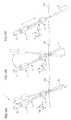
- Fig. 10 is a schematic view of operation of the manipulator 1 according to the embodiment of the invention described herein.
- the XY plane is defined by the drawing sheet plane
- the Z direction is defined by a direction toward the back of the drawing sheet.
- a grip 31 As the operator takes a grasp of a grip 31 to move the manipulator 1 in the YZ plane as shown in Fig. 10A , it causes a front end portion 21 of the manipulator 1 to move in the YZ plane within the body cavity 100 with the trocar 8 as center and in a symmetrical relation with respect to the grip 31.
- Fig. 11 is a block diagram of the manipulator 1 according to the embodiment of the invention described herein.
- the operating unit 3 includes a mode selection instruction portion 33, an acceleration sensor 91, and an amount-of-insertion sensor 92, and the extending/retracting unit 4 includes a moving distance sensor 93.
- the acceleration sensor 91 and amount-of-insertion sensor 92 define an amount-of-movement detection sensor.
- the mode selection instruction portion 33 is in its manual mode in which the extending/retracting movement driving portion 62 is not actuated, and while the button or the like is at the push, it causes the manual mode to be changed over to the electrically operated mode for controlling the extending/retracting movement driving portion 62.
- the manual and electrically operated modes will be described later.
- the acceleration sensor 91 is provided to sense the acceleration of the operating unit 3. As shown in Figs. 10A and 10B , the operator may move the operating unit 3 with the trocar 8 as a fulcrum. By detection of the operating unit 3 during movement, it is possible to detect the position of the front end portion 21.
- the amount-of-insertion sensor 92 is provided to detect the distance from the operating unit 3 to the trocar 8 shown in Fig. 10 . As shown in Fig. 10C , the operator may move the operating unit 3 relative to the trocar 8 in the insertion or withdrawal direction, and there is a change in that distance during this movement. By detection of such a change, it is possible for the operator to detect the amount of insertion of the insert unit 2, and the position of the front end portion 21 as well.
- the extending/retracting distance sensor 93 is provided to detect the moving distance of the extending/retracting unit 4.
- that sensor 93 is used to detect the angle of the first 41b or the second arm 41d with respect to the guide 42 in the extending/retracting unit 4 shown in Fig. 5 .
- the front end portion 21 may be moved without any change in the distance from the operating unit 3 to the trocar 8.
- the control unit 9 includes a first AD converter 94, a second AD converter 95, and a CPU 96.
- the first AD converter 94 is provided for AD conversion of signals from the acceleration sensor 91
- the second AD converter 95 is provided for AD conversion of signals from the amount-of-insertion sensor 92.
- the CPU 96 selects the manual mode or the electrically operated mode in response to a signal from the mode selection instruction portion 33: in the manual mode it does not drive the drive unit 6, and in the electrically operated mode, it controls the drive unit 6 in association with the acceleration sensor 91, amount-of-insertion sensor 92 and extending/retracting distance sensor 93.
- Fig. 12 is a schematic view of a first manual state of the manipulator 1 in the manual mode
- Fig. 13 is a schematic view of a second manual state of the manipulator 1 in the manual mode
- Fig. 14 is a schematic view of a third manual state of the manipulator 1 in the manual mode. Note here that the extending/retracting unit 4 is left out of Figs. 12 , 13 and 14 .
- a site of interest 101 is observed from the front in the first manual state. Assume here that the operator changes the site 101 of interest to a first site 101a of interest that is positioned at the back of the site 101. The operator must observe the first site 101a while rotating the manipulator 1 at the operating unit 3 with the trocar 8 as center, as can be seen from the second manual state shown in Fig. 13 .
- the front end portion 21 is away from the site 101, and an image of the site 101 seen on a monitor 17 becomes small while the front end portion 21 deviates from the front of the site 101, ending up with unsatisfactory observation.
- the operator passes from the second manual state to the third manual state shown in Fig. 14 , in which the operating unit 3 can be forced in to bring the front end portion 21 close to the site 101 so that satisfactory images can be well observed.
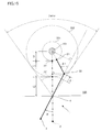
- Fig. 15 is descriptive of Equations (1) and (2) used for control of the manipulator 1 here in the electrically operated mode
- Fig. 16 is descriptive of Equations (3) and (4) used for control of the manipulator 1 here in the electrically operated mode.
- the front end portion 21 is indicated by a distal point positioned at the foremost end, the bendable portion 22 by an inflection point, the trocar 8 by a pivotal point, and the operating unit 3 by an operation point.
- control may be performed such that the distance from the front end portion 21 to the site 101 of interest is the same before and after control, and the front end portion 21 directs at the site 101 of interest.
- Fig. 15 the manipulator 1 before control is indicated by a two-dot chain line.
- D a distance from the site 101 of interest to a front end portion 21' before control
- L1 a distance from the front end portion 21' before control to a bendable portion 22' before control
- L2 a distance from the bendable portion 22' before control to the pivotal point for the trocar 8 by L2
- ⁇ max a controllable range
- the front end portion 21 after control may be located on a first circle 201 having a radius defined by the distance D with the site 101 as center.
- the bendable portion 22 after control may be located on a second circle 202 having a radius defined by a distance D+L1 with the site 101 as center.
- the controllable range ⁇ max is defined by an angle made between two tangent lines withdrawn from the trocar 8 to the second circle 202.
- 90° ⁇ 2 indicates that the acceleration detected by the acceleration sensor 91 shown in Fig. 11 , the rate of insertion found by integration of that acceleration, the amount of insertion Z2 detected by the amount-of-insertion sensor 92, etc. may optionally exceed predetermined thresholds. Higher rates of insertion or an increased amount of insertion Z2 imply that the operator desires to observe the site 101 of interest from the back.
- the predetermined thresholds may be previously stored in a storage (not shown) or the like or, alternatively, they may be set for each control depending on the situations of the site 101.
- Fig. 17 is a control flowchart for the manipulator 1 described herein
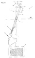
- Fig. 18 is a schematic view of the manipulator 1, described herein, in a state before the electrically operated mode of control is applied to it.
- the insert unit 2 of the manipulator 1 has already been inserted and placed in the body cavity 100 inside the skin, and that the endoscope in the manipulator 1 has taken images of the site 101 of interest.
- the electrically operated mode of control starts in response to an instruction from the mode selection instruction portion 33.
- Step 1 the turning angle ⁇ of the operating unit 3 is calculated from the outputs of the acceleration sensor 91 and amount-of-insertion sensor 92 (ST1).
- Step 2 whether or not the turning angle ⁇ found in Step 1 satisfies ⁇ max is determined (ST2).
- Step 2 when ⁇ max is not satisfied, the electrically operated mode is finished.
- the electrically operated mode is finished, an operator should be informed of that the angle is out of a controllable range by warnings.
- Step 2 when ⁇ max is satisfied, the amount of insertion Z2 of the operating unit 3 is calculated from the output of the amount-of-insertion sensor 92 (ST3).
- Step 4 whether or not the bending angle ⁇ of the bendable portion 2 of the manipulator 1 is smaller than 90° is then determined (ST4).
- Equations (1) and (2) are used in Step 5 to calculate target figures for the bending angle ⁇ 1 of the bendable portion 22 and the amount ⁇ 1 of extension and retraction of the extending/retracting unit 3 from the turning angle ⁇ and the amount of insertion Z2 (ST5).
- Step 6 the drive unit 6 is driven on the basis of the target figures found from Equations (1) and (2) (ST6). Note here that bending movement by the driving portion 61 for bending movement and extension/retraction by the driving portion 62 for extension/retraction may take place in any desired order.
- Equations (3) and (4) are used in Step 7 to calculate target figures for the bending angle ⁇ 2 of the bendable portion 22 and the amount ⁇ 2 of extension/ retraction of the extending/retracting unit 3 from the turning angle ⁇ and the amount of insertion Z2 (ST7).
- Step 8 the drive unit 6 is driven on the basis of the target figures found from Equations (3) and (4) (ST8). Note here that bending movement by the driving portion 61 for bending and extension/retraction by the driving portion 62 for extension/retraction may take place in any desired order.
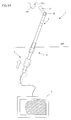
- Fig. 19 is a schematic view of the manipulator 1 of the invention described herein just after controlled in the electrically operated mode.
- the bendable portion 22 rotates by the bending angle ⁇ 1 and the extending/retracting unit 3 moves by the amount of movement ⁇ 1 on the basis of the target figures found from Equations (1) and (2), as shown in Fig. 19 .
- an image of the first site 101a of the site 101 of interest shows up on the monitor 12 on an enlarged scale.
- the conventional manipulator is very cumbersome because there is the need of performing separate operations for the position to which the manipulator is to be moved and the angle (posture) with respect to the site of interest.
- the manipulator 1 according to the embodiment of the invention described herein is easy to operate because the task to be performed by the operator is only to align the front end of the manipulator 1 with the site 101 of interest so that automated angle (posture) alignment of the manipulator 1 is achievable by the acceleration sensor 91 or amount-of-insertion sensor 92.
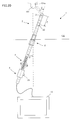
- Fig. 20 is a schematic view of the manipulator 1 of the invention just after completion of the electrically operated mode.
- That mode is cleared by the operator in response to the mode selection instruction portion 33.
- the manipulator 1 is actuated such that the bending angle ⁇ 1 of the bendable portion 22 or the amount of extension and retraction ⁇ 1 of the extending/retraction unit 4 are restored to the original conditions, as shown in Fig. 20 , and goes back to the linear state. Then, the operator may withdraw the manipulator 1 in the linear state from within the body cavity.
- bending movement by the driving portion 61 and extension/retraction by the driving portion 62 may take place in any desired order.
- bending movement by the driving portion 61 and extension/retraction by the driving portion 62 should take place with the images of the site 101 of interest showing up on the screen.
- Fig. 21 is a schematic view of the manipulator system 10 described herein.
- the manipulator system 10 here comprises a manipulator 1 including an endoscope as described above, an image processor 11, a monitor 12, and a light source device 13.
- the image processor 11 is provided to subject image signals from the endoscope in the manipulator 1 to a variety of image processing such as Y control, edge enhancement and output format conversion and send them out to the monitor 12.
- the monitor 12 presents the image signals received from the image processor 11 as images for observation.
- the light source device 13 is provided to generate illumination light from an illumination portion 21c of the front-end portion 21 shown in Fig. 2 through a light guide fiber (not shown) in the manipulator 1, and illuminates the site.
- Fig. 22 is a schematic view of another embodiment of the manipulator system 10.
- a gripping portion 21a is formed of forceps capable of taking a grip of the site 101 of interest and incising it or the like.
- the gripping portion 21a may be opened or closed by activation of a wire (not shown) by the operating unit 3 like scissors. This system is otherwise the same as the manipulator 1including an endoscope. Note here that the gripping portion 21a may be provided separately from the operating unit 3 for wireless remote control or the like.
- the manipulator according to the invention ensures that less experienced operators can be relieved of uncomfortableness because there is no shifting of the field of vision upon forced insertion into the body cavity or withdrawal.
Landscapes
- Health & Medical Sciences (AREA)
- Life Sciences & Earth Sciences (AREA)
- Surgery (AREA)
- Physics & Mathematics (AREA)
- Engineering & Computer Science (AREA)
- Optics & Photonics (AREA)
- Nuclear Medicine, Radiotherapy & Molecular Imaging (AREA)
- Public Health (AREA)
- Veterinary Medicine (AREA)
- General Health & Medical Sciences (AREA)
- Biomedical Technology (AREA)
- Heart & Thoracic Surgery (AREA)
- Medical Informatics (AREA)
- Molecular Biology (AREA)
- Animal Behavior & Ethology (AREA)
- Pathology (AREA)
- Radiology & Medical Imaging (AREA)
- Biophysics (AREA)
- Astronomy & Astrophysics (AREA)
- General Physics & Mathematics (AREA)
- Robotics (AREA)
- Mechanical Engineering (AREA)
- Multimedia (AREA)
- Signal Processing (AREA)
- Endoscopes (AREA)
- Instruments For Viewing The Inside Of Hollow Bodies (AREA)
- Manipulator (AREA)
Abstract
Description
- The present invention relates to a manipulator designed to be inserted into the body cavity, a manipulator system, and a manipulator control method.
- A manipulator having an elongate insert inserted in the body cavity has been extensively used, in which a bendable portion at the front end of the insert is pulled and bent by a wire or the like for the purpose of observing organs in the body cavity and giving medical treatments to them.
- For instance, Patent Publication 1 (
JP(A) 2005-74148 - Patent Publication 1:
JP(A) 2005-74148 - While an operator uses a conventional manipulator to observe a site of interest and give medical treatment to it, it is often necessary for the operator to observe the site of interest or give medical treatment to it from another angle. As the operator bends the manipulator without changing position, it causes the manipulator to be bent before reaching the site of interest with the result that the site of interest comes off from the field of vision. A less experienced operator would feel something wrong with that manipulator, and could not make full use of it.
- With such situations in mind, the invention has for its object to provide a manipulator, a manipulator system and a manipulator control method, which may relieve the operator of such un-comfortableness.
- According to one embodiment, the invention provides a manipulator including an insert unit capable of being inserted through the body cavity, an operating unit for operating the insert unit, an extending/retracting unit for moving the insert unit forward or backward, a drive unit for driving the insert unit and the extending/retracting unit, and a control unit for controlling the drive unit in association with operation of the operating unit, characterized in that the insert unit includes a bendable portion, and the drive unit includes a bending movement driving portion for generating driving force for bending the bendable portion and an extension/retraction driving portion for generating driving force for moving the extending/retracting unit forward or backward, characterized in that the control unit controls the extension/retraction driving portion and the bending movement driving portion in association with operation of the operating unit.
- With the manipulator, manipulator system and manipulator control method according to one embodiment of the invention, it is possible to relieve less experienced operators of un-comfortableness.
-
-
Fig. 1 is a diagrammatic view of themanipulator 1 according to one embodiment of the invention. -
Fig. 2 is an enlarged view of theinsert 2 according to one embodiment of the invention. -
Fig. 3 is a schematic view of theoperating unit 3 according to one embodiment of the invention. -
Fig. 4 is a schematic view of thedrive unit 6 according to one embodiment of the invention. -
Fig. 5 is an enlarged view of the extending/retractingunit 4 according to one embodiment of the invention. -
Fig. 6 is a schematic view of one example of operation of theinsert 2 according to one embodiment of the invention. -
Fig. 7 is a schematic view of one example of operation of the extending/retractingunit 4 according to one embodiment of the invention. -
Fig. 8 is a schematic view of another example of the extending/retractingunit 4. -
Fig. 9 is a schematic view of yet another example of the extending/retracting unit 4. -
Fig. 10 is a diagrammatic view of operation of themanipulator 1 according to one embodiment of the invention. -
Fig. 11 is a block diagram of themanipulator 1 according to one embodiment of the invention. -
Fig. 12 is a schematic view of the first manual operation of themanipulator 1 in a manual mode. -
Fig. 13 is a schematic view of the second manual operation of themanipulator 1 in the manual mode. -
Fig. 14 is a schematic view of the third manual operation of themanipulator 1 in the manual mode. -
Fig. 15 is descriptive of Equations (1) and (2) used for control of themanipulator 1 according to one embodiment of the invention in an electrically operated mode. -
Fig. 16 is descriptive of Equations (3) and (4) used for control of themanipulator 1 according to one embodiment of the invention in the electrically operated mode. -
Fig. 17 is a control flowchart for themanipulator 1 according to one embodiment of the invention. -
Fig. 18 is a schematic view of themanipulator 1 according to one embodiment of the invention before controlled in the electrically operated mode. -
Fig. 19 is a schematic view of themanipulator 1 according to one embodiment of the invention just after controlled in the electrically operated mode. -
Fig. 20 is a schematic view of themanipulator 1 according to one embodiment after the completion of the electrically operated mode. -
Fig. 21 is a diagrammatic view of themanipulator system 10 according to one embodiment of the invention. -
Fig. 22 is a diagrammatic view of another example of themanipulator system 10. - The
manipulator 1 and manipulator control method according to one embodiment of the invention are now explained. -
Fig. 1 is a diagrammatic view of themanipulator 1 according to one embodiment of the invention. - The
manipulator 1 according to one embodiment of the invention comprises aninsert unit 2, anoperating unit 3, and an extending/retracting unit 4. Themanipulator 1 includes theinsert unit 2 on a front-end (distal end) side and theoperating unit 3 on a base-end (proximal end) side, and includes the extending/retracting unit 4 on theoperating unit 3 side of theinsert unit 2. Theinsert unit 2 includes a front-end portion 21, abendable portion 22, and apower transmission portion 23. Theoperating unit 3 includes agrip 31, amain body 32, a modeselection instruction portion 33, and acoupling 34. The extending/retracting unit 4 includes alink portion 41 and aguide portion 42. -
Fig. 2 is an enlarged view of theinsert unit 2 of themanipulator 1 according to one embodiment of the invention. - The
insert unit 2 to be inserted through the body cavity includes the front-end portion 21,bendable portion 22 andpower transmission portion 23 in order from the front-end side. - The front-
end portion 21 includes a cylindrical, hardmain body 21a attached to the front end of themanipulator 1. Taking an endoscope as an example, the front-end portion 21 may have in it animaging portion 21b for taking images of the site of interest, alighting portion 21c for illuminating the site of interest, etc. A treatment tool (not shown) for giving treatment to the site of interest or the like may be built in the front-end portion 21. - The
bendable portion 22 includes a substantiallycylindrical block 22a to which the front-end portion 21 is attached, and a joint 22b for making a rotatable coupling between theblock 22a and thepower transmission portion 23 within a given angle range. Thepower transmission portion 23 is an elongate, substantially cylindrical shaft or like other member coupled to the front-end side to thebendable portion 22 by way of the joint 22b and on the base-end side to the extending/ retractingunit 4. - The front-
end portion 21 is fixedly provided with first andsecond wires second wires joint 22b in between. As an example, those positions are preferably symmetrical with respect to the center axis C of the cylindrical front-end portion 21. The first andsecond wires main body 32 of the operating unit shown inFig. 1 . - It is here to be noted that the structure of the
insert unit 2 is not limited to this; so it may be modified in various ways. For instance, a plurality ofblocks 22a and a plurality ofjoints 22b may be alternately combined into a bent state having a higher degree of freedom. More preferably, a set of adjoiningblock 22a and joint 22b in a plurality ofblock 22a/joints 22b combinations are rotated for each 90° about the axis of thebendable portion 22 in a straightly extended state or the center axis C of thepower transmission portion 23 such that theinsert unit 2 is three dimensionally movable. -
Fig. 3 is an enlarged view of theoperating unit 3 according to one embodiment of the invention. - The
operating unit 3 includes agrip 31 of which the operator takes a grip, amain body 32 of theoperating unit 3 having a built-indrive part 6 for operating movement or the like of theinsert unit 2 provided on the extending/retractingunit 4 side of thegrip 31 and extending/retractingunit 4 as described later, a modeselection instruction portion 33 that can be forced in themain body 32, and acoupling 34 coupled to the extending/retracting unit 4. - While the
grip 31 here is provided in a cylindrical form, it is to be understood that it may have any desired shape provided that it is easy to grip. Themain body 32 of the operating unit has the built-indrive unit 6 including a motor, a pulley and so on as described later. Themain body 32 of the operating unit takes up or feeds out the first andsecond wires bendable portion 22 of theinsert unit 2 shown inFig. 1 . Themain body 32 of the operating unit also takes up and feeds out alink activation wire 53 thereby causing extension and retraction of alink 41 of the extending/retractingunit 4 shown inFig. 1 . - The mode
selection instruction portion 33 comprises a push switch and so on. Usually, when the push switch or the like is not pushed down, the modeselection instruction portion 33 is set in a manual mode as the first mode, and as the push switch or the like is pushed down, the modeselection instruction part 33 issues an instruction to change the manual mode over to an electrically operated mode as the second mode. - The
coupling 34 has the first andsecond wires link activation wire 53 inserted through it, and is coupled to the extending/ retractingunit 4 shown inFig. 1 . -
Fig. 4 is a schematic view of thedrive unit 6 according to one embodiment of the invention. - The
drive unit 6 includes aportion 61 for driving bending movement, and aportion 62 for driving extension/retraction (not shown). The drivingportions portion 61 for driving bending movement is here explained. - The driving
portion 61 for driving bending movement includes amotor 61a, a drivingpulley 61b, and a driven orfollower pulley 61c. - One ends of the first and
second wires main body 21a of the front-end portion 21 shown inFig. 2 , and the other ends of the first andsecond wires pulley 61b. The first andsecond wires pulley 61c. The drivingpulley 61b is mounted on the rotary shaft of themotor 61a to take up and feed out the first andsecond wires pulley 61b in association with the rotation of themotor 61a. In turn, the rotational driving force of themotor 61a is transmitted to themain body 21a of the front-end portion 21. - In the example of
Fig. 4 , twoportions 61 for driving bending movement are symmetrically provided with respect to the center line C of thecoupling 34 for the purpose of explaining movement in a two-dimensional plane; however, it is to be understood that the invention is not always limited to twoportions 61; there may be one or two ormore portions 61 provided depending on the direction of rotation of the joint 22b. For instance, when one drivingportion 61 for driving bending movement is provided in combination with one wire for activation of the bendable portion, one wire for activation of the bendable portion may be looped around the driving pulley of theportion 61 for driving bending movement and the pulley mounted on the joint 22b. Then, the driving pulley is rotated by the rotational driving of one motor so that theblock 22a can be bent vertically by way of the wire for activation of the bendable portion and the pulley. For three-dimensional movement,additional portions 61 for driving bending movement may be provided before and after the drawing sheet. - It is to be understood that the structure of the
portion 61 for driving bending movement is not always limited to the aforesaid one; it may be modified in various ways. For instance, therespective joints 22b may be individually operated. The individually operable structure is preferable because there is an increased degree of freedom in the posture of thebendable portion 22. While theportion 61 for driving bending movement is located within theoperating unit 3 in the example shown inFig. 4 , it is to be noted that it may be provided separately from theoperating unit 3. That is, while theinsert unit 2 is positioned near the patient, theoperating unit 3 may be operated by the operator from a remote position. -
Fig. 5 is an enlarged view of the extending/ retractingunit 4 according to one embodiment of the invention. - The extending/retracting
unit 4 includes alink 41 coupled on one side to theoperating unit 3 and on the other side to theinsert unit 2, and aguide 42 for guiding operation of thelink 41. - The
link 41 includes afirst protrusion 41a that is mounted on thecoupling 34 and guided by theguide 42, afirst arm 41b that is rotatably mounted on thefirst protrusion 41a, asecond protrusion 41c that is attached to thepower transmission portion 23 and guided by theguide 42, asecond arm 41d that is rotatably mounted on thesecond protrusion 41c, and a connectingportion 41e for making a connection between the first andsecond arms - The
guide 42 is an elongate member that is fixed on one side to thecoupling 34 and on the other side to thepower transmission portion 23. Theguide 42 is provided with along opening 42a for receiving the first andsecond protrusions second protrusions elongate opening 42a. - In this embodiment, two
first arms 41b, twosecond arms 41d and two connectingportions 41e are provided with theguide 42 between them. Thelink activation wire 53 is wound around at least one connectingportion 41e, and themain body 32 of the operating unit takes up thelink activation wire 53 thereby extending and retracting thelink 41 having a so-called pantograph structure. - There is a cavity inside the first and
second arms second wires link activation wire 53, wirings for electronic components, etc. are passed. - It is here to be noted that
multiple links 41 andmultiple guides 42 may be provided to make the extending/ retracting distance long. - Movement of the
manipulator 1 is now explained. First, one example of bending movement is explained. -
Fig. 6 is a schematic view of one example of operation of theinsert unit 2 according to one embodiment of the invention. - The
manipulator 1 according to one embodiment of the invention actually operates in a three-dimensional space; for the sake of an easy understanding of the invention, however, operation of themanipulator 1 in a two-dimensional plane is here explained with reference to a schematic view likeFig. 6 . - Before activation of the
insert unit 2, the front-end portion 21,bendable portion 22, andpower transmission portion 23 are in a linear state as shown inFig. 1 . As thedrive unit 6 is activated by operation of theoperating unit 3 shown inFig. 3 , it causes the front-end portion 21 andblock 22a to be pulled by the first orsecond wire end portion 21 andbendable portion 22 bend at the joint 22b with respect to thepower transmission portion 23. -
Fig. 6A shows that thefirst wire 51 for activation of the bendable portion is being pulled by thedrive unit 6 shown inFig. 4 ; the front-end portion 21 andblock 22a are rotated in a direction indicated by an arrow A. It is here preferable that thesecond wire 52 for activation of the bendable portion is fed out.Fig. 6B shows that thesecond wire 52 for activation of the bendable part is being pulled by thedrive unit 6 shown inFig. 4 ; the front-end portion 21 andblock 22a are rotated in a direction indicated by an arrow B. It is here preferable that thefirst wire 51 for activation of the bendable portion is fed out. - It is here to be noted that for a structure including
multiple blocks 22a andjoints 22b, therespective joints 22b may be individually actuated. Such individual actuation is preferable because there is an increased degree of freedom in posture. Themain body 32 of the operating unit may be provided separately from the operating unit 3: themain body 32 may be positioned near the patient while theoperating unit 3 may be remote controlled from a remote position. -
Fig. 7 is a schematic view of an example of movement of the extending/retractingunit 4 according to this embodiment of the invention. - In the embodiment of the invention here, a pantograph mechanism is used as an example of the extending/retracting unit for generating extending/retracting movement of the
insert unit 2 of themanipulator 1. - As shown in
Fig. 5 , thelink activation wire 53 is wound around the connectingportion 41e of thelink 41. Thelink 41 is actuated by driving a motor (not shown) for taking up and feeding out thelink activation wire 53. - Referring to the extending/retracting
unit 4 in a state shown inFig. 7A , as the motor (not shown) is driven to take up thelink activation wire 53, it causes the connectingportion 41e to be pulled by thelink activation wire 53 so that thefirst arm 41b rotates about thefirst protrusion 41a. This in turn causes thesecond arm 41d having the link formed on it to rotate about thesecond protrusion 41c. - As a result, an angle formed between the first 41b and the
second arm 41d grows large, as shown inFig. 7B , so that thesecond protrusion 41c moves away from thefirst protrusion 41a along thelong opening 42a. Correspondingly, the distance between the first 41a and thesecond protrusion 41c becomes long, resulting in extension of the extending/retractingunit 4. -
Fig. 8 is a schematic view of another example of the extending/retractingunit 4. - The extending/retracting
unit 4 shown inFig. 8 includes onefirst arum 41b, onesecond arm 41d, and one connectingportion 41e on one side alone. Such construction may contribute to weight reductions. -
Fig. 9 is a schematic view of yet another example of the extending/retractingunit 4. - The extending/retracting
unit 4 shown inFig. 9 comprises adriving mechanism 6 as an example of the mechanism for generating extending/retracting movement of theinsert unit 2 of theendoscope 1, wherein a gear mechanism is located as an extending/retractingmovement driving portion 62 in theoperating unit 3. The extending/ retractingunit 4 includes amovable portion 43, astopper 44, and apinion 45. - Located in the
operating unit 3, the extending/retractingmovement driving portion 62 includes amotor 62a rotated by a power source (not shown), and amotor output shaft 62b for producing the driving force of themotor 62a. Agear portion 62c meshes with themotor output shaft 62b andpinion 45 to transmit the rotations of themotor output shaft 62b from thepinion 45 to theinsert unit 2 via themovable portion 43 so that the extending/retractingunit 4 and insertunit 2 advance toward or retreat from theoperating unit 3. - The
stopper 44 is larger in diameter than themovable portion 43 to limit movement of themovable portion 43, and should preferably be larger in diameter than thecoupling 34 of theoperating unit 3. Thepinion 45 converts the rotational motion of themotor output shaft 62b into linear motion and transmits it to theinsert unit 2 so that themovable portion 43 advances toward or retreats from theoperating unit 3. - In a state shown in
Fig. 9A , themovable portion 43 goes back to thecoupling 34 where an exposed part of themovable portion 43 becomes short in length. In a state shown inFig. 9B , as the extending/retractingmovement driving portion 62 is actuated from this state, it first causes rotation of themotor output shaft 62b by the driving force of themotor 62a. In turn, thegear portion 62c in mesh with themotor output shaft 62b rotates, and the pinion 23c in mesh with thegear portion 62c advances. - In the example shown in
Fig. 9 , two extending/retractingmovement driving portions 62 are symmetrically located with respect to the center line C of themovable portion 43 for the sake of an illustration of motion in the two-dimensional plane. However, it is to be noted that one or moresuch driving portions 62 may be provided. - It is also to be appreciated that the structure of the extending/retracting
movement driving portion 62 is not limited to the examples shown inFigs. 7 ,8 and9 ; various modifications may be made to it. For instance, the extending/retractingmovement driving portions 62 are provided within theoperating unit 3 in the examples shown inFigs. 7 ,8 and9 ; however, they may be provided separately from theoperating unit 3. That is, the extending/retractingmovement driving portions 62 may be positioned near the patient and theoperating unit 3 may be controlled from a remote position. - How
such manipulator 1 operates is now explained. -
Fig. 10 is a schematic view of operation of themanipulator 1 according to the embodiment of the invention described herein. - In
Fig. 10 , the XY plane is defined by the drawing sheet plane, and the Z direction is defined by a direction toward the back of the drawing sheet. Themanipulator 1 is inserted into abody cavity 100 by way of atrocar 8. - As the operator takes a grasp of a
grip 31 to move themanipulator 1 in the YZ plane as shown inFig. 10A , it causes afront end portion 21 of themanipulator 1 to move in the YZ plane within thebody cavity 100 with thetrocar 8 as center and in a symmetrical relation with respect to thegrip 31. - As the operator takes hold of the
grip 31 to move themanipulator 1 in the XZ direction as shown inFig. 10B , it causes thefront end portion 21 of themanipulator 1 to move in the XZ plane within thebody cavity 100 in a symmetrical relation to thegrip 31 with thetrocar 8 as center. - As the operator takes hold of the
grip 31 to move themanipulator 1 in the Z direction in a state shown inFig. 10c , it causes the front-end portion 21 of themanipulator 1 to move in thebody cavity 100 in the Z direction. -
Fig. 11 is a block diagram of themanipulator 1 according to the embodiment of the invention described herein. - The
operating unit 3 includes a modeselection instruction portion 33, anacceleration sensor 91, and an amount-of-insertion sensor 92, and the extending/retractingunit 4 includes a movingdistance sensor 93. Note here that theacceleration sensor 91 and amount-of-insertion sensor 92 define an amount-of-movement detection sensor. - With a switch such as a button held off, the mode
selection instruction portion 33 is in its manual mode in which the extending/retractingmovement driving portion 62 is not actuated, and while the button or the like is at the push, it causes the manual mode to be changed over to the electrically operated mode for controlling the extending/retractingmovement driving portion 62. The manual and electrically operated modes will be described later. - The
acceleration sensor 91 is provided to sense the acceleration of theoperating unit 3. As shown inFigs. 10A and 10B , the operator may move theoperating unit 3 with thetrocar 8 as a fulcrum. By detection of theoperating unit 3 during movement, it is possible to detect the position of thefront end portion 21. - The amount-of-
insertion sensor 92 is provided to detect the distance from theoperating unit 3 to thetrocar 8 shown inFig. 10 . As shown inFig. 10C , the operator may move theoperating unit 3 relative to thetrocar 8 in the insertion or withdrawal direction, and there is a change in that distance during this movement. By detection of such a change, it is possible for the operator to detect the amount of insertion of theinsert unit 2, and the position of thefront end portion 21 as well. - The extending/
retracting distance sensor 93 is provided to detect the moving distance of the extending/retractingunit 4. In the embodiment of the invention described herein, thatsensor 93 is used to detect the angle of the first 41b or thesecond arm 41d with respect to theguide 42 in the extending/retractingunit 4 shown inFig. 5 . With themanipulator 1 here in the electrically operated mode for driving thedrive unit 6, thefront end portion 21 may be moved without any change in the distance from theoperating unit 3 to thetrocar 8. By detection of the angle of the first 41b or thesecond arm 41d with respect to theguide 42 by means of the movingdistance sensor 93, it is possible to get the amount of movement of the extending/retractingunit 4 and detect the position of thefront end portion 21. - The
control unit 9 includes afirst AD converter 94, asecond AD converter 95, and aCPU 96. - The
first AD converter 94 is provided for AD conversion of signals from theacceleration sensor 91, and thesecond AD converter 95 is provided for AD conversion of signals from the amount-of-insertion sensor 92. - The
CPU 96 selects the manual mode or the electrically operated mode in response to a signal from the mode selection instruction portion 33: in the manual mode it does not drive thedrive unit 6, and in the electrically operated mode, it controls thedrive unit 6 in association with theacceleration sensor 91, amount-of-insertion sensor 92 and extending/retracting distance sensor 93. - Control of the
manipulator 1 having such structure is now explained. - One example of the manual mode in which there is no control of the
manipulator 1 is first explained. -
Fig. 12 is a schematic view of a first manual state of themanipulator 1 in the manual mode;Fig. 13 is a schematic view of a second manual state of themanipulator 1 in the manual mode; andFig. 14 is a schematic view of a third manual state of themanipulator 1 in the manual mode. Note here that the extending/retractingunit 4 is left out ofFigs. 12 ,13 and14 . - As shown in
Fig. 12 , a site ofinterest 101 is observed from the front in the first manual state. Assume here that the operator changes thesite 101 of interest to afirst site 101a of interest that is positioned at the back of thesite 101. The operator must observe thefirst site 101a while rotating themanipulator 1 at theoperating unit 3 with thetrocar 8 as center, as can be seen from the second manual state shown inFig. 13 . - In the second manual state, however, the
front end portion 21 is away from thesite 101, and an image of thesite 101 seen on a monitor 17 becomes small while thefront end portion 21 deviates from the front of thesite 101, ending up with unsatisfactory observation. Here, the operator passes from the second manual state to the third manual state shown inFig. 14 , in which theoperating unit 3 can be forced in to bring thefront end portion 21 close to thesite 101 so that satisfactory images can be well observed. - In the manual mode, an experienced operator could pass swiftly, if instinctively, from the first manual state of
Fig. 12 to the third manual state ofFig. 14 . - Control of the
manipulator 1 in the electrically operated mode is now explained. -
Fig. 15 is descriptive of Equations (1) and (2) used for control of themanipulator 1 here in the electrically operated mode, andFig. 16 is descriptive of Equations (3) and (4) used for control of themanipulator 1 here in the electrically operated mode. Note here that inFigs. 15 and16 , thefront end portion 21 is indicated by a distal point positioned at the foremost end, thebendable portion 22 by an inflection point, thetrocar 8 by a pivotal point, and theoperating unit 3 by an operation point. - In the electrically operated mode of control of the
manipulator 1 described herein, such a manual mode of tasks performed by the operator as shown typically inFigs. 12 ,13 and14 is automated. For instance, control may be performed such that the distance from thefront end portion 21 to thesite 101 of interest is the same before and after control, and thefront end portion 21 directs at thesite 101 of interest. - In
Fig. 15 , themanipulator 1 before control is indicated by a two-dot chain line. Assume now that a distance from thesite 101 of interest to a front end portion 21' before control is indicated by D, a distance from the front end portion 21' before control to a bendable portion 22' before control by L1, a distance from the bendable portion 22' before control to the pivotal point for thetrocar 8 by L2, and a controllable range by θmax. - In order to make the distance between the
front end portion 21 after control and thesite 101 of interest the same as the distance before control, thefront end portion 21 after control may be located on afirst circle 201 having a radius defined by the distance D with thesite 101 as center. Further in order to direct thefront end portion 21 toward thesite 101, thebendable portion 22 after control may be located on asecond circle 202 having a radius defined by a distance D+L1 with thesite 101 as center. Note here that the controllable range θmax is defined by an angle made between two tangent lines withdrawn from thetrocar 8 to thesecond circle 202. - Consequently, the amount δ1 of extending/retracting movement that is a controlled variable (amount of control) and the bending angle φ1 may be found from
Fig. 15 as mentioned below. However, φ1≦90°.

- A specific case: 90° < φ2 is now explained. This control may be applied to such as when, upon insertion of the
manipulator 1, it is impossible for the operator to direct thefront end portion 21 toward thesite 101 of interest unless the bending angle φ of thebendable portion 22 is greater than 90°. As is the case withFig. 15 , the amount δ2 of extending/retracting movement that is a controlled variable (amount of control) and the bending angle φ2 may be found fromFig. 16 as mentioned below.

- It is here to be appreciated that 90° <φ2 indicates that the acceleration detected by the
acceleration sensor 91 shown inFig. 11 , the rate of insertion found by integration of that acceleration, the amount of insertion Z2 detected by the amount-of-insertion sensor 92, etc. may optionally exceed predetermined thresholds. Higher rates of insertion or an increased amount of insertion Z2 imply that the operator desires to observe thesite 101 of interest from the back. The predetermined thresholds may be previously stored in a storage (not shown) or the like or, alternatively, they may be set for each control depending on the situations of thesite 101. - While the embodiment of the invention here has been explained with reference to two-dimensional movements for the sake of an easy understanding of the invention, it is to be noted that the same may hold true for three-dimensional movements. For three-dimensional movements, the first 201 and the
second circle 202 may be replaced by spheres for consideration. -
Fig. 17 is a control flowchart for themanipulator 1 described herein, andFig. 18 is a schematic view of themanipulator 1, described herein, in a state before the electrically operated mode of control is applied to it. - Suppose now that, as shown in
Fig. 18 , theinsert unit 2 of themanipulator 1 has already been inserted and placed in thebody cavity 100 inside the skin, and that the endoscope in themanipulator 1 has taken images of thesite 101 of interest. The electrically operated mode of control starts in response to an instruction from the modeselection instruction portion 33. - In
Step 1, the turning angle θ of theoperating unit 3 is calculated from the outputs of theacceleration sensor 91 and amount-of-insertion sensor 92 (ST1). - In
Step 2, whether or not the turning angle θ found inStep 1 satisfies θ≦θmax is determined (ST2). - In
Step 2, when θ≦θmax is not satisfied, the electrically operated mode is finished. When the electrically operated mode is finished, an operator should be informed of that the angle is out of a controllable range by warnings. - In
Step 2, when θ≦θmax is satisfied, the amount of insertion Z2 of theoperating unit 3 is calculated from the output of the amount-of-insertion sensor 92 (ST3). - In
Step 4, whether or not the bending angle φ of thebendable portion 2 of themanipulator 1 is smaller than 90° is then determined (ST4). - When the bending angle φ of the
bendable portion 2 of themanipulator 1 is found to be smaller than 90° inStep 4, Equations (1) and (2) are used in Step 5 to calculate target figures for the bending angle φ1 of thebendable portion 22 and the amount δ1 of extension and retraction of the extending/retractingunit 3 from the turning angle θ and the amount of insertion Z2 (ST5). - The operation then goes to
Step 6 in which thedrive unit 6 is driven on the basis of the target figures found from Equations (1) and (2) (ST6). Note here that bending movement by the drivingportion 61 for bending movement and extension/retraction by the drivingportion 62 for extension/retraction may take place in any desired order. - When the bending angle φ of the
bendable portion 2 of themanipulator 1 is found to be greater than 90° inStep 4, Equations (3) and (4) are used in Step 7 to calculate target figures for the bending angle φ2 of thebendable portion 22 and the amount δ2 of extension/ retraction of the extending/retractingunit 3 from the turning angle θ and the amount of insertion Z2 (ST7). - The operation then goes to
Step 8 in which thedrive unit 6 is driven on the basis of the target figures found from Equations (3) and (4) (ST8). Note here that bending movement by the drivingportion 61 for bending and extension/retraction by the drivingportion 62 for extension/retraction may take place in any desired order. -
Fig. 19 is a schematic view of themanipulator 1 of the invention described herein just after controlled in the electrically operated mode. - In the
manipulator 1 after controlled in the electrically operated mode, for instance, thebendable portion 22 rotates by the bending angle φ1 and the extending/retractingunit 3 moves by the amount of movement δ1 on the basis of the target figures found from Equations (1) and (2), as shown inFig. 19 . As a result, an image of thefirst site 101a of thesite 101 of interest shows up on themonitor 12 on an enlarged scale. - The conventional manipulator is very cumbersome because there is the need of performing separate operations for the position to which the manipulator is to be moved and the angle (posture) with respect to the site of interest. However, the
manipulator 1 according to the embodiment of the invention described herein is easy to operate because the task to be performed by the operator is only to align the front end of themanipulator 1 with thesite 101 of interest so that automated angle (posture) alignment of themanipulator 1 is achievable by theacceleration sensor 91 or amount-of-insertion sensor 92. -
Fig. 20 is a schematic view of themanipulator 1 of the invention just after completion of the electrically operated mode. - After controlled in the electrically operated mode, that mode is cleared by the operator in response to the mode
selection instruction portion 33. Here if the operator judges from the output of theacceleration sensor 91 or amount-of-insertion sensor 92 that themanipulator 1 moves a given distance in the withdrawal direction, themanipulator 1 is actuated such that the bending angle φ1 of thebendable portion 22 or the amount of extension and retraction δ1 of the extending/retraction unit 4 are restored to the original conditions, as shown inFig. 20 , and goes back to the linear state. Then, the operator may withdraw themanipulator 1 in the linear state from within the body cavity. - Note here that bending movement by the driving
portion 61 and extension/retraction by the drivingportion 62 may take place in any desired order. Preferably, bending movement by the drivingportion 61 and extension/retraction by the drivingportion 62 should take place with the images of thesite 101 of interest showing up on the screen. -
Fig. 21 is a schematic view of themanipulator system 10 described herein. - The
manipulator system 10 here comprises amanipulator 1 including an endoscope as described above, animage processor 11, amonitor 12, and alight source device 13. - The
image processor 11 is provided to subject image signals from the endoscope in themanipulator 1 to a variety of image processing such as Y control, edge enhancement and output format conversion and send them out to themonitor 12. Themonitor 12 presents the image signals received from theimage processor 11 as images for observation. Thelight source device 13 is provided to generate illumination light from anillumination portion 21c of the front-end portion 21 shown inFig. 2 through a light guide fiber (not shown) in themanipulator 1, and illuminates the site. -
Fig. 22 is a schematic view of another embodiment of themanipulator system 10. - A gripping
portion 21a is formed of forceps capable of taking a grip of thesite 101 of interest and incising it or the like. The grippingportion 21a may be opened or closed by activation of a wire (not shown) by theoperating unit 3 like scissors. This system is otherwise the same as the manipulator 1including an endoscope. Note here that the grippingportion 21a may be provided separately from theoperating unit 3 for wireless remote control or the like. - It is to be appreciated that the invention is not limited to some embodiments described herein. The explanation of some specific embodiments includes many detailed matters for the sake of illustration; however, it would be obvious to those skilled in the art that even when various variations and changes are applied to these detailed matters, they do not depart from the scope of the invention. Thus, the illustrative embodiments of the invention are described without a loss of the generality of what is claimed and without any limitation on what is claimed.
- The manipulator according to the invention ensures that less experienced operators can be relieved of uncomfortableness because there is no shifting of the field of vision upon forced insertion into the body cavity or withdrawal.
-
- 1:
- Manipulator
- 2:
- Insert unit
- 21:
- Front-end portion
- 22:
- Bendable portion
- 23:
- Power transmission portion
- 3:
- Operating unit
- 31:
- Grip
- 32:
- Main body of the operating unit
- 33:
- Mode selection instruction portion
- 34:
- Coupling
- 4:
- Extending/retracting unit
- 41:
- Link
- 42:
- Guide
- 5:
- Wire
- 51:
- First bendable-portion activation wire
- 52:
- Second bendable-portion activation wire
- 53:
- Link activating wire
- 6:
- Drive unit
- 61:
- Bending movement driving portion
- 62:
- Extension/retraction driving portion
- 8:
- Trocar
- 9:
- Control unit
- 91:
- Acceleration sensor
- 92:
- Amount-of-insertion sensor
- 93:
- Extending/retracting distance sensor
- 94:
- First AD converter
- 95:
- Second AD converter
- 96:
- CPU
- 10:
- Manipulator system
- 11:
- Image processor
- 12:
- Monitor
- 13:
- Light source device
- 100:
- Body cavity
- 101:
- Site of interest
Claims (7)
- A manipulator, including:an insert unit capable of being inserted through the body cavity,an operating unit for operating the insert unit,an extending/retracting unit for moving the insert unit forward or backward,a drive unit for driving the insert unit and the extending/retracting unit, anda control unit for controlling the drive unit in association with operation of the operating unit, characterized in that:the insert unit includes a bendable portion, andthe drive unit includes a bending movement driving portion for generating driving force for bending the bendable portion, and an extension/retraction driving portion for generating driving force for moving the extending/retracting unit forward or backward, wherein:the control unit controls the extension/retraction driving portion and the bending movement driving portion in association with operation of the operating unit.
- A manipulator as recited in claim 1, where the operating unit further includes a mode selection instruction portion for selecting either one of a manual mode, and a control mode in which the operating unit controls the drive unit in association with operation of the operating unit.
- A manipulator as recited in claim 1 or 2, wherein the operating unit includes an amount-of-movement sensor capable of detecting an amount of movement of the operating unit, and
the control unit controls the drive unit in association of an amount of movement of the operating unit detected by the amount-of-movement sensor. - A manipulator as recited in claim 3, wherein the control unit performs control such that the front-end portion after controlled directs at the site of interest.
- A manipulator system, characterized by comprising:a manipulator as recited in any one of claims 1 to 4 and including an endoscope,an image processor for applying image processing to image signals obtained from the endoscope, anda monitor for displaying image signals sent from the image processor.
- A method for controlling a manipulator including:an insert unit capable of being inserted in the body cavity,an operating unit for operating the insert unit, andan extending/retracting unit for moving the insert unit forward or backward, characterized by comprising steps of:calculating a turning angle of the operating unit,calculating an amount of insertion of the operating unit, andcontrolling a bending angle of a bendable portion included in the insert unit and an amount of extension/retraction of the extending/retracting unit in association with the turning angle and amount of insertion of the operating unit.
- A method for controlling a manipulator as recited in claim 6, wherein the step of controlling the bending angle of the bendable portion and the amount of extension/retraction of the extending/retracting unit is performed such that the front-end portion after controlled directs at the site of interest.
Applications Claiming Priority (2)
| Application Number | Priority Date | Filing Date | Title |
|---|---|---|---|
| US201361806459P | 2013-03-29 | 2013-03-29 | |
| PCT/JP2014/051200 WO2014156242A1 (en) | 2013-03-29 | 2014-01-22 | Manipulator, manipulator system, and manipulator control method |
Publications (2)
| Publication Number | Publication Date |
|---|---|
| EP2979609A1 true EP2979609A1 (en) | 2016-02-03 |
| EP2979609A4 EP2979609A4 (en) | 2016-11-30 |
Family
ID=51623245
Family Applications (1)
| Application Number | Title | Priority Date | Filing Date |
|---|---|---|---|
| EP14772996.6A Withdrawn EP2979609A4 (en) | 2013-03-29 | 2014-01-22 | Manipulator, manipulator system, and manipulator control method |
Country Status (5)
| Country | Link |
|---|---|
| US (1) | US20160051127A1 (en) |
| EP (1) | EP2979609A4 (en) |
| JP (1) | JP6141410B2 (en) |
| CN (1) | CN105072973B (en) |
| WO (1) | WO2014156242A1 (en) |
Families Citing this family (9)
| Publication number | Priority date | Publication date | Assignee | Title |
|---|---|---|---|---|
| JP6358811B2 (en) * | 2014-02-13 | 2018-07-18 | オリンパス株式会社 | Manipulator and manipulator system |
| JP2019037353A (en) * | 2017-08-23 | 2019-03-14 | 敏明 高橋 | Arthroscope operation system |
| US11547481B2 (en) * | 2018-01-11 | 2023-01-10 | Covidien Lp | Systems and methods for laparoscopic planning and navigation |
| WO2020112217A1 (en) * | 2018-09-18 | 2020-06-04 | Brigham Young University | Developable and collapsable shaft deployment mechanism |
| EP3852641B1 (en) | 2018-09-18 | 2023-10-18 | Brigham Young University | Developable and collapsable external cutting or gripping mechanism |
| CN112955078B (en) | 2018-09-18 | 2023-10-27 | 布莱阿姆青年大学 | Expandable and foldable internal cutting mechanism |
| CN110721380B (en) * | 2019-11-18 | 2022-07-05 | 北京大学人民医院(北京大学第二临床医学院) | Device capable of automatically implementing trachea cannula |
| CN119136719A (en) * | 2022-02-01 | 2024-12-13 | C·R·巴德股份有限公司 | Ureteroscopic device and system including catheter control system and related methods |
| CN116327080B (en) * | 2023-03-29 | 2024-06-14 | 拜孚(苏州)医疗科技有限公司 | Medical instrument fixing device |
Family Cites Families (14)
| Publication number | Priority date | Publication date | Assignee | Title |
|---|---|---|---|---|
| US5658238A (en) * | 1992-02-25 | 1997-08-19 | Olympus Optical Co., Ltd. | Endoscope apparatus capable of being switched to a mode in which a curvature operating lever is returned and to a mode in which the curvature operating lever is not returned |
| US5657429A (en) * | 1992-08-10 | 1997-08-12 | Computer Motion, Inc. | Automated endoscope system optimal positioning |
| JP2005074148A (en) | 2003-09-03 | 2005-03-24 | Olympus Corp | Endoscope |
| US8231610B2 (en) * | 2006-09-06 | 2012-07-31 | National Cancer Center | Robotic surgical system for laparoscopic surgery |
| JP5214187B2 (en) * | 2007-07-13 | 2013-06-19 | オリンパスメディカルシステムズ株式会社 | Endoscope, endoscope apparatus, and operation method of endoscope apparatus |
| JP5301867B2 (en) * | 2008-04-07 | 2013-09-25 | オリンパスメディカルシステムズ株式会社 | Medical manipulator system |
| EP2301411B1 (en) * | 2009-01-15 | 2012-12-12 | Olympus Medical Systems Corp. | Endoscope system |
| US8523900B2 (en) * | 2009-02-03 | 2013-09-03 | Terumo Kabushiki Kaisha | Medical manipulator |
| EP2486846A4 (en) * | 2009-10-09 | 2016-07-13 | Olympus Corp | Endoscope device |
| JP4862105B2 (en) * | 2009-12-10 | 2012-01-25 | オリンパスメディカルシステムズ株式会社 | Medical manipulator |
| JP2012115471A (en) * | 2010-11-30 | 2012-06-21 | Olympus Corp | Medical treatment instrument, and manipulator |
| JP5669590B2 (en) * | 2011-01-20 | 2015-02-12 | オリンパス株式会社 | Master-slave manipulator and medical master-slave manipulator |
| JP2012187311A (en) * | 2011-03-11 | 2012-10-04 | Olympus Corp | Medical treatment tool and manipulator |
| JP5851204B2 (en) * | 2011-10-31 | 2016-02-03 | オリンパス株式会社 | Tubular insertion device |
-
2014
- 2014-01-22 JP JP2015508117A patent/JP6141410B2/en active Active
- 2014-01-22 EP EP14772996.6A patent/EP2979609A4/en not_active Withdrawn
- 2014-01-22 CN CN201480018260.XA patent/CN105072973B/en active Active
- 2014-01-22 WO PCT/JP2014/051200 patent/WO2014156242A1/en not_active Ceased
-
2015
- 2015-09-29 US US14/868,998 patent/US20160051127A1/en not_active Abandoned
Also Published As
| Publication number | Publication date |
|---|---|
| CN105072973B (en) | 2018-01-23 |
| JP6141410B2 (en) | 2017-06-07 |
| WO2014156242A1 (en) | 2014-10-02 |
| CN105072973A (en) | 2015-11-18 |
| US20160051127A1 (en) | 2016-02-25 |
| JPWO2014156242A1 (en) | 2017-02-16 |
| EP2979609A4 (en) | 2016-11-30 |
Similar Documents
| Publication | Publication Date | Title |
|---|---|---|
| EP2979609A1 (en) | Manipulator, manipulator system, and manipulator control method | |
| JP5197980B2 (en) | Multi-joint bending mechanism and medical device with multi-joint bending mechanism | |
| EP3103374B1 (en) | Traction balance adjustment mechanism, manipulator, and manipulator system | |
| US11517384B2 (en) | Surgical system and method for controlling the same | |
| JP6001189B2 (en) | manipulator | |
| EP2629655B1 (en) | Highly articulated robotic probes and methods of production and use of such probes | |
| CN103153159B (en) | Endoscopes and treatment instruments for endoscopes | |
| EP3111821A1 (en) | Slack correction mechanism, manipulator, and manipulator system | |
| EP2127591A1 (en) | Articulated bending mechanism and articulated medicaldevice with articulated bending mechanism | |
| CN106028900A (en) | Manipulator and manipulator system | |
| JP5675223B2 (en) | Endoscope and hardness adjustment device | |
| JP2012187311A (en) | Medical treatment tool and manipulator | |
| WO2015194317A1 (en) | Endoscope device | |
| US20110178367A1 (en) | Endoscopic device with end effector mechanism | |
| US20170049523A1 (en) | Treatment instrument adaptor and surgical manipulator system | |
| WO2018070042A1 (en) | Medical instrument and surgical system | |
| EP2630925A1 (en) | Treatment tool for medical use, and manipulator | |
| CN107072477B (en) | Insertion apparatus | |
| US20240383129A1 (en) | Continuum robot control system and continuum robot control method | |
| US20200100813A1 (en) | Medical overtube device | |
| WO2025085415A1 (en) | Systems and methods for controlling a sequential workflow | |
| WO2025085438A1 (en) | Systems and methods for actuating an instrument system |
Legal Events
| Date | Code | Title | Description |
|---|---|---|---|
| PUAI | Public reference made under article 153(3) epc to a published international application that has entered the european phase |
Free format text: ORIGINAL CODE: 0009012 |
|
| 17P | Request for examination filed |
Effective date: 20150929 |
|
| AK | Designated contracting states |
Kind code of ref document: A1 Designated state(s): AL AT BE BG CH CY CZ DE DK EE ES FI FR GB GR HR HU IE IS IT LI LT LU LV MC MK MT NL NO PL PT RO RS SE SI SK SM TR |
|
| AX | Request for extension of the european patent |
Extension state: BA ME |
|
| DAX | Request for extension of the european patent (deleted) | ||
| RAP1 | Party data changed (applicant data changed or rights of an application transferred) |
Owner name: OLYMPUS CORPORATION |
|
| RIN1 | Information on inventor provided before grant (corrected) |
Inventor name: YOSHIMURA, KATSUHIKO |
|
| A4 | Supplementary search report drawn up and despatched |
Effective date: 20161103 |
|
| RIC1 | Information provided on ipc code assigned before grant |
Ipc: A61B 1/00 20060101AFI20161027BHEP Ipc: G02B 23/24 20060101ALI20161027BHEP |
|
| STAA | Information on the status of an ep patent application or granted ep patent |
Free format text: STATUS: EXAMINATION IS IN PROGRESS |
|
| 17Q | First examination report despatched |
Effective date: 20171012 |
|
| STAA | Information on the status of an ep patent application or granted ep patent |
Free format text: STATUS: THE APPLICATION IS DEEMED TO BE WITHDRAWN |
|
| 18D | Application deemed to be withdrawn |
Effective date: 20181211 |