EP2979584B1 - Pillow - Google Patents
Pillow Download PDFInfo
- Publication number
- EP2979584B1 EP2979584B1 EP15173456.3A EP15173456A EP2979584B1 EP 2979584 B1 EP2979584 B1 EP 2979584B1 EP 15173456 A EP15173456 A EP 15173456A EP 2979584 B1 EP2979584 B1 EP 2979584B1
- Authority
- EP
- European Patent Office
- Prior art keywords
- bridging section
- wings
- pillow
- thickness
- wing
- Prior art date
- Legal status (The legal status is an assumption and is not a legal conclusion. Google has not performed a legal analysis and makes no representation as to the accuracy of the status listed.)
- Active
Links
Images



Classifications
-
- A—HUMAN NECESSITIES
- A47—FURNITURE; DOMESTIC ARTICLES OR APPLIANCES; COFFEE MILLS; SPICE MILLS; SUCTION CLEANERS IN GENERAL
- A47C—CHAIRS; SOFAS; BEDS
- A47C7/00—Parts, details, or accessories of chairs or stools
- A47C7/36—Supports for the head or the back
- A47C7/38—Supports for the head or the back for the head, e.g. detachable
- A47C7/383—Detachable or loose head- or neck-supports, e.g. horse-shoe shaped
-
- A—HUMAN NECESSITIES
- A47—FURNITURE; DOMESTIC ARTICLES OR APPLIANCES; COFFEE MILLS; SPICE MILLS; SUCTION CLEANERS IN GENERAL
- A47G—HOUSEHOLD OR TABLE EQUIPMENT
- A47G9/00—Bed-covers; Counterpanes; Travelling rugs; Sleeping rugs; Sleeping bags; Pillows
- A47G9/10—Pillows
-
- A—HUMAN NECESSITIES
- A47—FURNITURE; DOMESTIC ARTICLES OR APPLIANCES; COFFEE MILLS; SPICE MILLS; SUCTION CLEANERS IN GENERAL
- A47G—HOUSEHOLD OR TABLE EQUIPMENT
- A47G9/00—Bed-covers; Counterpanes; Travelling rugs; Sleeping rugs; Sleeping bags; Pillows
- A47G9/10—Pillows
- A47G9/1081—Pillows comprising a neck support, e.g. a neck roll
-
- A—HUMAN NECESSITIES
- A47—FURNITURE; DOMESTIC ARTICLES OR APPLIANCES; COFFEE MILLS; SPICE MILLS; SUCTION CLEANERS IN GENERAL
- A47G—HOUSEHOLD OR TABLE EQUIPMENT
- A47G9/00—Bed-covers; Counterpanes; Travelling rugs; Sleeping rugs; Sleeping bags; Pillows
- A47G9/10—Pillows
- A47G2009/1018—Foam pillows
Definitions
- the present invention provides a pillow containing particulate material such as beads or balls (a "bean pillow"), which is particularly suitable for use during travel.
- Pillows are known that are particularly suitable for use during travel.
- Such pillows often are substantially U-shaped in plan view so that the pillow can be wrapped around the back and sides of the neck of the user to support the user's head.
- Some such pillows are inflatable.
- Another such pillow, which is sold by the applicant for this patent application is substantially U-shaped in plan view and contains beads or balls (i.e. is a "bean pillow”).
- This bean pillow has the advantage that it does not require inflation before use.
- US 2010/0205744 discloses an inflatable pillow.
- the aim of the present invention is to provide an improved pillow with respect to the known pillows referred to above.
- the present invention provides a pillow, the pillow comprising two wings, and a bridging section connecting the wings, wherein the wings and bridging section together form a substantially U shaped shape in plan view, and the surface of each wing is formed of a surface material, and the wings contain particulate material to provide support for the surface material, wherein the thickness of the thinnest portion of the bridging section is less than the thickness of the thickest portion of the wings, and wherein the bridging section contains particulate material, and comprises means for restricting the amount of particulate material in the bridging section, to restrict the thickness of the bridging section, and wherein the bridging section comprises one ore more channels containing the particulate material and extending between the wings.
- the thickness of the thinnest portion of the bridging section is less than the thickness of the thickest portion of the wings means that the bridging section can be folded and the wings brought together more easily in comparison with known pillows in which the thickness of the bridging section is equal to or greater than the thickness of the wings.
- the folded pillow is also less bulky than known pillows when folded, and thus takes up a smaller space in the user's luggage.
- the pillow of the present invention is intended to be worn around the neck of the user, with the bridging section behind the neck and a wing on each side of the neck, so that the front portion of the neck is open.
- the bridging section provides support for the back of the user's head and the wings provide support for the side of the head.
- the thickness of the thinnest portion of the bridging section is less than the thickness of the thickest portion of the wings does not detract from the comfort of the user when using the pillow, and in fact increases the user's comfort because the smaller thickness of the bridging section does not force the user's head so far away from the surface on which the pillow is resting. Hence the user's neck can be held in a straighter position when the pillow is being used.
- the term “thickness” refers to the height dimension when the pillow is viewed in plan view and the wings and bridging section form a substantially U shaped shape. This dimension is in the direction perpendicular to the surface on which the pillow is resting in normal use. The thinnest part, correspondingly, is the thinnest in the same height dimension.
- the provision of two wings separated by a bridging section which is shaped so that the particulate material either does not pass through the bridging section at all or is restricted in passing through the bridging section might present problems in manufacture as the step of filling the wings with particulate material will be either slowed down or must take place in two steps.
- the present inventors have discovered that the filling step is surprisingly efficient or can be carried out in two separate steps relatively easily by suitable manufacturing steps, such as filling the wings near the bridging section.
- the surface of the wings is preferably, but not necessarily, formed of the same material as the surface of the bridging section.
- the wings are filled with the particulate material.
- the bridging section or part of the bridging section is filled with the particulate material.
- the two wings form a pair of wings.
- a pair of wings provides equal support for each side of the user's head.
- the thickness of the thickest portion of the bridging section is less than the thickness of the thickest portion of the wings. This provides that the bridging section is easier to fold at each point between the wings in comparison with known pillows in which the thickness of the bridging section is equal to or greater than the thickness of the wings.
- the thickness of the thickest portion of each wing is from 60mm to 120mm, more preferably from 70mm to 110mm, even more preferably from 80mm to 100mm, and most preferably from 85mm to 95mm.
- the thickness of the thinnest portion of the bridging section is from 5mm to 15mm, more preferably 7mm to 13mm and most preferably from 8mm to 12mm.
- the thickness of the thickest portion of the bridging section is from 50mm to 90mm, more preferably 60mm to 80mm, and most preferably 65mm to 75mm.
- the ratio of the thickness of the thinnest portion of the bridging section to the thickness of the thickest portion of each wing is from 1:4 to 1: 24, more preferably from 1:4 to 1:14, more preferably from 1:6 to 1:12, more preferably from 1:8 to 1:12, most preferably from 1:8 to 1:10.
- the ratio of the thickness of the thickest portion of the bridging section to the thickness of the thickest portion of each wing is from 1:0.6 to 1:2.5, more preferably from 1:0.9 to 1:2, more preferably from 1:1 to 1:1.5, more preferably from 1:1.1 to 1:1.5, most preferably from 1:1.2 to 1:1.4.
- the ratio of the thickness of the thickest portion of the bridging section to the thickness of the thickest portion of each wing is from 1:0.8 to 1:4.
- the ratio of the thickness of the thinnest portion of the bridging section to the thickness of the thickest portion of the bridging section is from 1:3 to 1:18, more preferably from 1:4 to 1:12, more preferably from 1:4 to 1:9, more preferably from 1:5 to 1:9, more preferably from 1:5 to 1:8, most preferably from 1:6 to 1:8.
- the thinnest portion of the bridging section is equidistant from each wing.
- the bridging section is easiest to fold at a point equidistant from each wing and so the pillow can be folded into a particularly small arrangement.
- the bridging section according to the invention comprises one or more channels containing the particulate material and extending between the wings.
- One such channel may be provided on the outer edge of the bridging section.
- One such channel may be provided on the inner edge of the bridging section.
- the bridging section comprises a cushioning means preferably containing a material different from the particulate material.
- the cushioning means is defined by stitching in the surface material of the bridging section.
- the material of the cushioning means is a foam material.
- the foam material is provided inside the bridging section.
- the foam material is held in place by stitching.
- the stitching joins a surface of the bridging section to an opposing surface of the bridging section.
- the cushioning means or foam material is substantially rectangular or substantially trapezoidal in plan view.
- the cushioning means forms a head zone.
- the bridging section has an axis extending between the wings, and the longer sides of the substantially rectangular or substantially trapezoidal shape are substantially parallel to the axis of the bridging section. This provides a wide cushioning means to support the head of the user.
- the difference in thickness between the thinnest portion of the bridging section and the thickest portion of the wings is from 70mm to 110mm, more preferably 80mm to 100mm, most preferably 85mm to 95mm.
- Such differences in thickness provide a particularly advantageous balance of allowing the pillow to be folded easily while providing sufficient support for the back of the user's head.
- the difference in thickness between the thinnest portion of the bridging section and the thickest portion of the wings is from 45mm to 115mm.
- each wing has a free end located away from a point where each respective wing is connected to the bridging section, and the distance between the wings at the point that each wing is connected to the bridging section is larger than the distance between the wings at a point adjacent to the free end of each wing. This means that the wings wrap more closely around the neck and thereby provide closer support for the sides of the user's head.
- At least part of the bridging section contains the or a particulate material.
- at least part of the bridging section does not contain the or a particulate material.
- the means for restricting the amount of particulate material in the bridging section comprises stitching joining a surface of the bridging section to an opposing surface of the bridging section.
- the stitching restricts the size of the space formed by the opposing surfaces of the bridging section.
- the means for restricting the amount of particulate material in the bridging section comprises padding or cushioning means provided in the bridging section.
- the surface of the bridging section is formed of a surface material, and the particulate material in the bridging section provides support for the surface material.
- the bridging section contains material other than the particulate material.
- the pillow further comprises a loop attached to one of the wings and a fastening means or fastener attached to the other, the fastening means or fastener being receivable in the loop to fasten the wings together.
- the fastening means or fastener comprises a button or toggle.
- the surface of the bridging section is formed from a separate piece of material from the surface of the wings.
- the surface material of the wings and/or bridging section comprises fabric or a stretchy or elastic material or fabric, for example Lycra (RTM).
- RTM Lycra
- the surface material of the wings and/or bridging section is formed of plurality of layers, and preferably one or more of the layers comprises a stretchy or elastic material, for example Lycra (RTM).
- RTM Lycra
- the surface of the bridging section or wings is formed from a plurality of, preferably two, pieces of material stitched together to form a seam.
- the particulate material comprises beads, balls, beans, buckwheat, oats or any combination thereof.
- the particulate material may comprise pieces of memory foam.
- the particulate material comprises beads, balls or beans.
- the cushioning means contains a substance different from the particulate material.
- the pillow is described its unloaded state i.e. when the pillow has not been manipulated, loaded or moulded by the user.
- a pillow 10 comprising a pair of wings 12, and a bridging section 14 connecting the wings 12.
- the wings 12 and bridging section 14 together form a substantially U shaped shape in plan view.
- the surface of the wings 12 and bridging section 14 is formed of a surface material, and the wings 12 and bridging section 14 contain beads in this embodiment (or other particulate material such as balls or beans or any combination thereof in other embodiments) to provide support for the surface material.
- the thickness (or depth - the dimension in the direction away from the viewer in Fig. 1 ) of the thinnest portion of the bridging section 14 is less than the thickness of the thickest portion of the wings 12. This is most clearly shown in Figs.
- the bridging section 14 comprises a cushioning means 16 containing a foam material.
- the cushioning means has a constant thickness of approximately 10mm.
- the cushioning means 16 provides the thinnest portion of the bridging section 14, but in other embodiments the thinnest portion may be provided elsewhere.
- the bridging section 14 does not contain the particulate material, and so the surface of the bridging section 14 is not supported by the particulate material.
- the cushioning means 16 forms a head zone to support the user's head.
- the thickness of the thickest portion of the wings 12 is shown by arrows X.
- the thickness of a portion of the bridging section 14 is shown by arrows Y.
- Fig. 1 the wings 12 are divided from the bridging section 14 by stitching 28.
- the wings 12 and bridging section 14 may be divided differently, for example the wings 12 may extend further into the bridging section 14.
- the thickest portion of the wings 12 (which has the same thickness in each wing 12) is approximately halfway between the free end 22 of each wing 12 and the outer edge of the bridging section 14, but the invention is not limited to this.
- the thinnest portion of the bridging section 14 is equidistant from each wing 12. This is because the centre line CL of the pillow 10 shown in Fig. 1 , which is equidistant from each wing 12, passes through the cushioning means 16.
- the pillow 10 is axisymmetric about the centre line CL.
- the surface of the bridging section 14 is formed from two separate pieces of material 30, 32 stitched together to form a seam on line of stitching 34 (preferably horizontal) around the middle in the depth direction of the bridging section 14.
- the surface of each wing 12 is formed from two separate pieces of material 36, 38 stitched together to form a seam 40 (preferably horizontal) around the middle in the depth direction of each wing 12.
- Lycra (RTM) (elastane) is used as the material for the surface of the bridging section 14 and the wings 12 in this embodiment, but the invention is not limited to this, and other fabrics instead may be used.
- Lycra (RTM) provides a stretchy material that allows the pillow 10 to be easily moulded for the user, but other stretchy materials may be used.
- the surface of the bridging section 14 need not be formed of a fabric such as Lycra (RTM).
- An additional, inner layer of material for example Lycra (RTM), may be provided in the bridging section 14 and/or each of the wings 12.
- the or each additional layer may be stitched to the or each respective outer layer of the bridging section 14 and/or the wings 12.
- a tube is inserted into a small hole left in the seam and beads are pumped along the tube at high pressure to fill the pillow 10. After filling the hole in the seam is immediately sewn up.
- the filling with beads typically takes under 3 second to complete because there are no internal walls inside the pillow 10 to slow down the filling. Internal walls would present a serious impediment to filling of a pillow with beads. Such internal walls would also significantly reduce the effectiveness of the product as a pillow because the beads must be allowed to move freely throughout the pillow in order to achieve a moulded comfortable fit specifically for the user. This is different from known inflatable pillows, which are suitable for use during travel but contain such internal walls in order to ensure proper inflation.
- the bridging section 14 does not contain particulate material, care must be taken as the two wings must be filled with beads separately, either sequentially, or simultaneously for example by two operatives or in two operations.
- the tube may be passed through the inside of the bridging section 14 to fill a far wing 12 before or after the near wing 12 has been filled.
- the means may also make passing the tube through the bridging section 14 difficult.
- Such known inflatable pillows typically are fabricated from weldable fabrics that are welded by heat sealing. Such fabrics are welded together while the pillow is flat and deflated on a press.
- the beads are polystyrene.
- a loop 18, and a button 20 on a flap of material, are provided on the outer edges of respective wings 12.
- the loop 18 and a button 20 are provided approximately halfway between the free end 22 of each wing 12 and the outer edge of the bridging section 14.
- the button 20 can be received in the loop 18 to fasten the wings 12 together and to retain the pillow 10 in the folded position.
- the thickness of the thickest portion of each wing is approximately 90mm. In addition, in this embodiment the thickness of the thickest portion of the bridging section 14 is approximately 70mm.
- the thickest portion of the bridging section 14 is provided at the two points that the bridging section 14 connects to each wing 12. This is best shown in Fig. 2 .
- the ratio of the thickness of the thinnest portion of the bridging section to the thickness of the thickest portion of each wing is approximately 1:9.
- the ratio of the thickness of the thickest portion of the bridging section to the thickness of the thickest portion of each wing is approximately 1:1.3.
- the ratio of the thickness of the thinnest portion of the bridging section to the thickness of the thickest portion of the bridging section is approximately 1:7.
- the bridging section 14 comprises two channels 24, 26 containing beads and extending between the wings 12.
- One channel 24 is provided on the outer edge of the bridging section 14 (the upper edge as shown in Fig. 1 ).
- the other channel 26 is provided on the inner edge of the bridging section 14 (the lower edge as shown in Fig. 1 ).
- the channels 24, 26 allow beads to pass between the ends of the bridging section 14, and between the wings 12, past the cushioning means 16.
- the cushioning means 16 is defined by stitching in the surface material of the bridging section 14.
- the foam material of the cushioning means is substantially trapezoidal in plan view and the stitching surrounds the foam material to maintain the foam material in position.
- Other material may be used instead of foam material.
- the stitching defining the cushioning means 16 and the foam material of the cushioning means 16 provides means for restricting the amount of particulate material in the bridging section 14, to restrict the thickness of the bridging section 16.
- the stitching defining the cushioning means 16 joins the lower surface of the bridging section 14 to the upper, opposing surface of the bridging section 14.
- the stitching restricts the size of the space formed by these opposing surfaces of the bridging section 14.
- the foam material takes up space in the bridging section 14 that would otherwise be occupied by the particulate material.
- the bridging section 14 has an axis extending between the wings 12 (in this embodiment substantially parallel with the straight section of the outer edge of the bridging section 14), and the longer sides of the substantially trapezoidal shape of the cushioning means 16 are substantially parallel to the axis of the bridging section 14. This provides a wide cushioning means to support the head of the user.
- the user places the bridging section 14 behind the head of the user and the user wraps the wings 12 around the neck of the user.
- the pillow 10 is then placed upon a surface and the bridging section 14 provides support for the back of the user's head and the wings 12 provide support for the sides of the user's head.
- the difference in thickness between the thinnest portion of the bridging section 14 (at the centre line CL) and the thickest portion of the wings 12 is approximately 80mm.
- each wing 12 is provided away from a point that each respective wing 12 is connected to the bridging section 14.
- the distance between the wings 12 at the point that each wing 12 is connected to the bridging section 14 is larger than the distance between the wings 12 at a point adjacent to the free end 22 of each wing 12. This is clearly shown in Fig. 1 where the wings 12 are closer at their free ends 22 than at their other ends where they connect to the bridging section 14.
- Figs. 4 and 5 show the detail of the bridging section 14 and it can be seen from Figs. 4 and 5 that the upper surface of the cushioning means 16 is below the highest point of the rest of the bridging section 14, in particular is below the highest point of channels 24 and 26.
- the pillow 10 is symmetrical about a horizontal plane and, in this embodiment, about the seam 34 of the bridging section 14 and the seam 40 of each wing 12. Therefore, the lower (underside) surface (not shown in Figs. 4 and 5 ) of the cushioning means 16 is above the lowest point of the rest of the bridging section 14, in particular is above the lowest point of channels 24 and 26.
- the cushioning means 16 provides the thinnest portion of the bridging section 14 in this embodiment, but in other embodiments the thinnest portion may be provided elsewhere, for example in the channel 24 and/or 26.
- Figs. 6 and 7 show the thickness of the thickest portion of the wings 12 is shown by arrows X.
- Figs. 6 and 7 show that, in this embodiment, the thickest portion of the wings 12 (which has the same thickness in each wing 12) is approximately halfway between the free end 22 of each wing 12 and the outer edge of the bridging section 14, but the invention is not limited to this.
- the loop 18 and/or the button 20 is/are provided respectively on the seam 40 of each wing 12 i.e. approximately in the middle in the depth direction of each wing 12.
- the bridging section 14 curves (when viewed in plan; towards the bottom in Fig. 1 ) from where it connects to each wing 12 to a substantially flat section comprising the cushioning means 16 and the channels 24 and 26.
- the cushioning means may not be provided; instead, for example, a single channel may extend between the wings 12.
- the width of a portion of the wings 12 (when viewed in plan) is substantially the same as the width of a portion of the bridging section 14.
- the width of each wing 12 is the distance between the outer edge of the wing 12 and the inner edge of the wing 12 with reference to the pillow 10 shown in Fig. 1 .
- the width of the bridging section 14 is the distance between the outer edge and the inner edge.
- the width of the wings 12 and bridging section is from 120mm to 140mm.
- the maximum width of the bridging section 14 is approximately 140mm and the minimum width of the bridging section 14 is approximately 120mm.
- the minimum width of the bridging section 14 is at the centre line CL.
- the longer dimension of the substantially trapezoidal cushioning means 16, which is substantially parallel with the longer side is approximately 120mm.
Landscapes
- Health & Medical Sciences (AREA)
- General Health & Medical Sciences (AREA)
- Otolaryngology (AREA)
- Pulmonology (AREA)
- Bedding Items (AREA)
- Mattresses And Other Support Structures For Chairs And Beds (AREA)
Description
- The present invention provides a pillow containing particulate material such as beads or balls (a "bean pillow"), which is particularly suitable for use during travel.
Pillows are known that are particularly suitable for use during travel. Such pillows often are substantially U-shaped in plan view so that the pillow can be wrapped around the back and sides of the neck of the user to support the user's head. Some such pillows are inflatable. Another such pillow, which is sold by the applicant for this patent application, is substantially U-shaped in plan view and contains beads or balls (i.e. is a "bean pillow"). This bean pillow has the advantage that it does not require inflation before use.
US 2010/0205744 discloses an inflatable pillow.
The aim of the present invention is to provide an improved pillow with respect to the known pillows referred to above.
The present invention provides a pillow, the pillow comprising two wings, and a bridging section connecting the wings, wherein the wings and bridging section together form a substantially U shaped shape in plan view, and the surface of each wing is formed of a surface material, and the wings contain particulate material to provide support for the surface material, wherein the thickness of the thinnest portion of the bridging section is less than the thickness of the thickest portion of the wings, and wherein the bridging section contains particulate material, and comprises means for restricting the amount of particulate material in the bridging section, to restrict the thickness of the bridging section, and wherein the bridging section comprises one ore more channels containing the particulate material and extending between the wings. - The fact that the thickness of the thinnest portion of the bridging section is less than the thickness of the thickest portion of the wings means that the bridging section can be folded and the wings brought together more easily in comparison with known pillows in which the thickness of the bridging section is equal to or greater than the thickness of the wings. The folded pillow is also less bulky than known pillows when folded, and thus takes up a smaller space in the user's luggage.
- The pillow of the present invention is intended to be worn around the neck of the user, with the bridging section behind the neck and a wing on each side of the neck, so that the front portion of the neck is open. The bridging section provides support for the back of the user's head and the wings provide support for the side of the head.
- The fact that the thickness of the thinnest portion of the bridging section is less than the thickness of the thickest portion of the wings does not detract from the comfort of the user when using the pillow, and in fact increases the user's comfort because the smaller thickness of the bridging section does not force the user's head so far away from the surface on which the pillow is resting. Hence the user's neck can be held in a straighter position when the pillow is being used.
- In this specification the term "thickness" refers to the height dimension when the pillow is viewed in plan view and the wings and bridging section form a substantially U shaped shape. This dimension is in the direction perpendicular to the surface on which the pillow is resting in normal use. The thinnest part, correspondingly, is the thinnest in the same height dimension.
- The provision of two wings separated by a bridging section which is shaped so that the particulate material either does not pass through the bridging section at all or is restricted in passing through the bridging section might present problems in manufacture as the step of filling the wings with particulate material will be either slowed down or must take place in two steps. The present inventors have discovered that the filling step is surprisingly efficient or can be carried out in two separate steps relatively easily by suitable manufacturing steps, such as filling the wings near the bridging section.
- The surface of the wings is preferably, but not necessarily, formed of the same material as the surface of the bridging section.
- Preferably, the wings are filled with the particulate material. Preferably, the bridging section or part of the bridging section is filled with the particulate material.
- Preferably, the two wings form a pair of wings. A pair of wings provides equal support for each side of the user's head.
- Preferably, the thickness of the thickest portion of the bridging section is less than the thickness of the thickest portion of the wings. This provides that the bridging section is easier to fold at each point between the wings in comparison with known pillows in which the thickness of the bridging section is equal to or greater than the thickness of the wings.
- Preferably, the thickness of the thickest portion of each wing is from 60mm to 120mm, more preferably from 70mm to 110mm, even more preferably from 80mm to 100mm, and most preferably from 85mm to 95mm.
- Preferably, the thickness of the thinnest portion of the bridging section is from 5mm to 15mm, more preferably 7mm to 13mm and most preferably from 8mm to 12mm.
- Preferably, the thickness of the thickest portion of the bridging section is from 50mm to 90mm, more preferably 60mm to 80mm, and most preferably 65mm to 75mm.
- Preferably, the ratio of the thickness of the thinnest portion of the bridging section to the thickness of the thickest portion of each wing is from 1:4 to 1: 24, more preferably from 1:4 to 1:14, more preferably from 1:6 to 1:12, more preferably from 1:8 to 1:12, most preferably from 1:8 to 1:10.
- Preferably, the ratio of the thickness of the thickest portion of the bridging section to the thickness of the thickest portion of each wing is from 1:0.6 to 1:2.5, more preferably from 1:0.9 to 1:2, more preferably from 1:1 to 1:1.5, more preferably from 1:1.1 to 1:1.5, most preferably from 1:1.2 to 1:1.4.
- Preferably, the ratio of the thickness of the thickest portion of the bridging section to the thickness of the thickest portion of each wing is from 1:0.8 to 1:4.Preferably, the ratio of the thickness of the thinnest portion of the bridging section to the thickness of the thickest portion of the bridging section is from 1:3 to 1:18, more preferably from 1:4 to 1:12, more preferably from 1:4 to 1:9, more preferably from 1:5 to 1:9, more preferably from 1:5 to 1:8, most preferably from 1:6 to 1:8.
Preferably, the thinnest portion of the bridging section is equidistant from each wing. As a result, the bridging section is easiest to fold at a point equidistant from each wing and so the pillow can be folded into a particularly small arrangement.
The bridging section according to the invention comprises one or more channels containing the particulate material and extending between the wings. One such channel may be provided on the outer edge of the bridging section. One such channel may be provided on the inner edge of the bridging section.
Preferably, the bridging section comprises a cushioning means preferably containing a material different from the particulate material. Preferably, the cushioning means is defined by stitching in the surface material of the bridging section.
Preferably, the material of the cushioning means is a foam material. Preferably, the foam material is provided inside the bridging section. Preferably, the foam material is held in place by stitching. Preferably, the stitching joins a surface of the bridging section to an opposing surface of the bridging section.
Preferably, the cushioning means or foam material is substantially rectangular or substantially trapezoidal in plan view.
Preferably, the cushioning means forms a head zone.
Preferably, the bridging section has an axis extending between the wings, and the longer sides of the substantially rectangular or substantially trapezoidal shape are substantially parallel to the axis of the bridging section. This provides a wide cushioning means to support the head of the user. - Preferably, the difference in thickness between the thinnest portion of the bridging section and the thickest portion of the wings is from 70mm to 110mm, more preferably 80mm to 100mm, most preferably 85mm to 95mm. Such differences in thickness provide a particularly advantageous balance of allowing the pillow to be folded easily while providing sufficient support for the back of the user's head.
- Preferably, the difference in thickness between the thinnest portion of the bridging section and the thickest portion of the wings is from 45mm to 115mm.
- Preferably, each wing has a free end located away from a point where each respective wing is connected to the bridging section, and the distance between the wings at the point that each wing is connected to the bridging section is larger than the distance between the wings at a point adjacent to the free end of each wing. This means that the wings wrap more closely around the neck and thereby provide closer support for the sides of the user's head.
- Preferably, at least part of the bridging section contains the or a particulate material. Alternatively, at least part of the bridging section does not contain the or a particulate material.
- Preferably, the means for restricting the amount of particulate material in the bridging section comprises stitching joining a surface of the bridging section to an opposing surface of the bridging section. The stitching restricts the size of the space formed by the opposing surfaces of the bridging section. There is preferably at least one line of stitching located within the edge of the bridging section, preferably at least two lines of stitching.
- Preferably, the means for restricting the amount of particulate material in the bridging section comprises padding or cushioning means provided in the bridging section.
- Preferably, the surface of the bridging section is formed of a surface material, and the particulate material in the bridging section provides support for the surface material.
- Preferably, the bridging section contains material other than the particulate material. Preferably, the pillow further comprises a loop attached to one of the wings and a fastening means or fastener attached to the other, the fastening means or fastener being receivable in the loop to fasten the wings together. Preferably, the fastening means or fastener comprises a button or toggle.
- Preferably, the surface of the bridging section is formed from a separate piece of material from the surface of the wings.
- Preferably, the surface material of the wings and/or bridging section comprises fabric or a stretchy or elastic material or fabric, for example Lycra (RTM).
- Preferably, the surface material of the wings and/or bridging section is formed of plurality of layers, and preferably one or more of the layers comprises a stretchy or elastic material, for example Lycra (RTM).
- Preferably, the surface of the bridging section or wings is formed from a plurality of, preferably two, pieces of material stitched together to form a seam.
- Preferably, the particulate material comprises beads, balls, beans, buckwheat, oats or any combination thereof. The particulate material may comprise pieces of memory foam. Preferably the particulate material comprises beads, balls or beans.
- Preferably, the cushioning means contains a substance different from the particulate material.
- A preferred embodiment of the invention will now be described, purely by way of example, with reference to the drawings in which:
-
Figure 1 is a plan view of a pillow according to the preferred embodiment of the invention; -
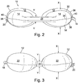
Figure 2 is a front elevation view of the pillow ofFigure 1 ; -
Figure 3 is a rear elevation view of the pillow ofFigure 1 ; -
Figure 4 is an isometric view of the pillow ofFigure 1 ; -
Figure 5 is front view of the pillow ofFigure 1 showing the detail of the bridging section; -
Figure 6 is right side view of the pillow ofFigure 1 , and -
Figure 7 is a left side view of the pillow ofFigure 1 . - Throughout this specification the pillow is described its unloaded state i.e. when the pillow has not been manipulated, loaded or moulded by the user.
- Referring to
Fig. 1 , apillow 10 is provided comprising a pair ofwings 12, and abridging section 14 connecting thewings 12. As shown inFig. 1 , thewings 12 andbridging section 14 together form a substantially U shaped shape in plan view. The surface of thewings 12 andbridging section 14 is formed of a surface material, and thewings 12 andbridging section 14 contain beads in this embodiment (or other particulate material such as balls or beans or any combination thereof in other embodiments) to provide support for the surface material. The thickness (or depth - the dimension in the direction away from the viewer inFig. 1 ) of the thinnest portion of thebridging section 14 is less than the thickness of the thickest portion of thewings 12. This is most clearly shown inFigs. 2 and 3 . In the present embodiment, thebridging section 14 comprises a cushioning means 16 containing a foam material. In the present embodiment, the cushioning means has a constant thickness of approximately 10mm. In the present embodiment, the cushioning means 16 provides the thinnest portion of thebridging section 14, but in other embodiments the thinnest portion may be provided elsewhere. - In other embodiments, the
bridging section 14 does not contain the particulate material, and so the surface of thebridging section 14 is not supported by the particulate material. - The cushioning means 16 forms a head zone to support the user's head.
- Referring to
Figs. 2 and 3 , the thickness of the thickest portion of thewings 12 is shown by arrows X. The thickness of a portion of thebridging section 14 is shown by arrows Y. However, it is not possible to see the thickness of the cushioning means 16 inFigs. 2 and 3 and so it is not possible to see the thickness of the thinnest portion of thebridging section 14 inFigs. 2 and 3 . - In
Fig. 1 thewings 12 are divided from thebridging section 14 by stitching 28. However, thewings 12 andbridging section 14 may be divided differently, for example thewings 12 may extend further into thebridging section 14. - In this embodiment, the thickest portion of the wings 12 (which has the same thickness in each wing 12) is approximately halfway between the
free end 22 of eachwing 12 and the outer edge of thebridging section 14, but the invention is not limited to this. - In addition, in the present embodiment the thinnest portion of the
bridging section 14 is equidistant from eachwing 12. This is because the centre line CL of thepillow 10 shown inFig. 1 , which is equidistant from eachwing 12, passes through the cushioning means 16. Thepillow 10 is axisymmetric about the centre line CL. - Referring to
Fig. 2 , the surface of thebridging section 14 is formed from two separate pieces ofmaterial bridging section 14. Similarly, the surface of eachwing 12 is formed from two separate pieces ofmaterial wing 12. Lycra (RTM) (elastane) is used as the material for the surface of thebridging section 14 and thewings 12 in this embodiment, but the invention is not limited to this, and other fabrics instead may be used. However, Lycra (RTM) provides a stretchy material that allows thepillow 10 to be easily moulded for the user, but other stretchy materials may be used. - In addition, in the embodiment where the
bridging section 14 does not contain the particulate material, the surface of thebridging section 14 need not be formed of a fabric such as Lycra (RTM). - An additional, inner layer of material, for example Lycra (RTM), may be provided in the
bridging section 14 and/or each of thewings 12. The or each additional layer may be stitched to the or each respective outer layer of thebridging section 14 and/or thewings 12. - During filling of the
pillow 10, a tube is inserted into a small hole left in the seam and beads are pumped along the tube at high pressure to fill thepillow 10. After filling the hole in the seam is immediately sewn up. The filling with beads typically takes under 3 second to complete because there are no internal walls inside thepillow 10 to slow down the filling. Internal walls would present a serious impediment to filling of a pillow with beads. Such internal walls would also significantly reduce the effectiveness of the product as a pillow because the beads must be allowed to move freely throughout the pillow in order to achieve a moulded comfortable fit specifically for the user. This is different from known inflatable pillows, which are suitable for use during travel but contain such internal walls in order to ensure proper inflation. - In other embodiments where the
bridging section 14 does not contain particulate material, care must be taken as the two wings must be filled with beads separately, either sequentially, or simultaneously for example by two operatives or in two operations. For example, the tube may be passed through the inside of thebridging section 14 to fill afar wing 12 before or after thenear wing 12 has been filled. - Care must also be taken when filling the
bridging section 14 when thebridging section 14 contains particulate material because the means for restricting the amount of particulate material in the bridging section may make filling thebridging section 14 difficult. The means may also make passing the tube through thebridging section 14 difficult. - Such known inflatable pillows typically are fabricated from weldable fabrics that are welded by heat sealing. Such fabrics are welded together while the pillow is flat and deflated on a press.
- Preferably, the beads are polystyrene.
- A
loop 18, and abutton 20 on a flap of material, are provided on the outer edges ofrespective wings 12. Theloop 18 and abutton 20 are provided approximately halfway between thefree end 22 of eachwing 12 and the outer edge of thebridging section 14. - When the
pillow 10 is folded about the centre line CL thebutton 20 can be received in theloop 18 to fasten thewings 12 together and to retain thepillow 10 in the folded position. - In this embodiment the thickness of the thickest portion of each wing is approximately 90mm. In addition, in this embodiment the thickness of the thickest portion of the
bridging section 14 is approximately 70mm. The thickest portion of thebridging section 14 is provided at the two points that thebridging section 14 connects to eachwing 12. This is best shown inFig. 2 . - In this embodiment, the ratio of the thickness of the thinnest portion of the bridging section to the thickness of the thickest portion of each wing is approximately 1:9.
- In this embodiment, the ratio of the thickness of the thickest portion of the bridging section to the thickness of the thickest portion of each wing is approximately 1:1.3.
- In this embodiment, the ratio of the thickness of the thinnest portion of the bridging section to the thickness of the thickest portion of the bridging section is approximately 1:7.
- In the present embodiment, the
bridging section 14 comprises twochannels wings 12. Onechannel 24 is provided on the outer edge of the bridging section 14 (the upper edge as shown inFig. 1 ). Theother channel 26 is provided on the inner edge of the bridging section 14 (the lower edge as shown inFig. 1 ). Thechannels bridging section 14, and between thewings 12, past the cushioning means 16. - The cushioning means 16 is defined by stitching in the surface material of the
bridging section 14. The foam material of the cushioning means is substantially trapezoidal in plan view and the stitching surrounds the foam material to maintain the foam material in position. Other material may be used instead of foam material. - In this embodiment, the stitching defining the cushioning means 16 and the foam material of the cushioning means 16 provides means for restricting the amount of particulate material in the
bridging section 14, to restrict the thickness of thebridging section 16. The stitching defining the cushioning means 16 joins the lower surface of thebridging section 14 to the upper, opposing surface of thebridging section 14. The stitching restricts the size of the space formed by these opposing surfaces of thebridging section 14. In addition, the foam material takes up space in thebridging section 14 that would otherwise be occupied by the particulate material. - The
bridging section 14 has an axis extending between the wings 12 (in this embodiment substantially parallel with the straight section of the outer edge of the bridging section 14), and the longer sides of the substantially trapezoidal shape of the cushioning means 16 are substantially parallel to the axis of thebridging section 14. This provides a wide cushioning means to support the head of the user. - In use of the
pillow 10 the user places thebridging section 14 behind the head of the user and the user wraps thewings 12 around the neck of the user. Thepillow 10 is then placed upon a surface and thebridging section 14 provides support for the back of the user's head and thewings 12 provide support for the sides of the user's head. - In this embodiment, the difference in thickness between the thinnest portion of the bridging section 14 (at the centre line CL) and the thickest portion of the
wings 12 is approximately 80mm. - The
free end 22 of eachwing 12 is provided away from a point that eachrespective wing 12 is connected to thebridging section 14. The distance between thewings 12 at the point that eachwing 12 is connected to thebridging section 14 is larger than the distance between thewings 12 at a point adjacent to thefree end 22 of eachwing 12. This is clearly shown inFig. 1 where thewings 12 are closer at their free ends 22 than at their other ends where they connect to thebridging section 14. - It can be seen from
Figs. 2 and 3 that the central portion of thebridging section 14, i.e. the portion adjacent to the centre line CL is considerably thinner than the thickest portion of thewings 12. -
Figs. 4 and5 show the detail of thebridging section 14 and it can be seen fromFigs. 4 and5 that the upper surface of the cushioning means 16 is below the highest point of the rest of thebridging section 14, in particular is below the highest point ofchannels pillow 10 is symmetrical about a horizontal plane and, in this embodiment, about theseam 34 of thebridging section 14 and theseam 40 of eachwing 12. Therefore, the lower (underside) surface (not shown inFigs. 4 and5 ) of the cushioning means 16 is above the lowest point of the rest of thebridging section 14, in particular is above the lowest point ofchannels bridging section 14 in this embodiment, but in other embodiments the thinnest portion may be provided elsewhere, for example in thechannel 24 and/or 26. -
Figs. 6 and 7 show the thickness of the thickest portion of thewings 12 is shown by arrows X.Figs. 6 and 7 show that, in this embodiment, the thickest portion of the wings 12 (which has the same thickness in each wing 12) is approximately halfway between thefree end 22 of eachwing 12 and the outer edge of thebridging section 14, but the invention is not limited to this. - The
loop 18 and/or thebutton 20 is/are provided respectively on theseam 40 of eachwing 12 i.e. approximately in the middle in the depth direction of eachwing 12. - Referring to
Figs. 1 ,4 and5 , thebridging section 14 curves (when viewed in plan; towards the bottom inFig. 1 ) from where it connects to eachwing 12 to a substantially flat section comprising the cushioning means 16 and thechannels wings 12. - In this embodiment, the width of a portion of the wings 12 (when viewed in plan) is substantially the same as the width of a portion of the
bridging section 14. The width of eachwing 12 is the distance between the outer edge of thewing 12 and the inner edge of thewing 12 with reference to thepillow 10 shown inFig. 1 . The width of thebridging section 14 is the distance between the outer edge and the inner edge. - In this embodiment, the width of the
wings 12 and bridging section is from 120mm to 140mm. The maximum width of thebridging section 14 is approximately 140mm and the minimum width of thebridging section 14 is approximately 120mm. In this embodiment, the minimum width of thebridging section 14 is at the centre line CL. - In this embodiment, the longer dimension of the substantially trapezoidal cushioning means 16, which is substantially parallel with the longer side, is approximately 120mm. The shorter dimension of the substantially trapezoidal cushioning means 16, which is substantially parallel with the shorter side, is approximately 80mm.
Claims (11)
- A pillow (10) comprising:two wings (12), anda bridging section (14) connecting the wings (12),wherein the wings (12) and bridging section (14) together form a substantially U shaped shape in plan view, and the surface of each wing (12) is formed of a surface material, and the wings (12) contain particulate material to provide support for the surface material,wherein the thickness of the thinnest portion of the bridging section (14) is less than the thickness of the thickest portion of the wings (12),wherein the bridging section (14) contains particulate material, and comprises means for restricting the amount of particulate material in the bridging section (14), to restrict the thickness of the bridging section (14), andwherein the bridging section (14) comprises one or more channels (24, 26) containing the particulate material and extending between the wings (12).
- A pillow (10) according to claim 1, wherein the thickness of the thickest portion of the bridging section (14) is less than the thickness of the thickest portion of each wing (12).
- A pillow (10) according to claim 1 or 2, wherein the bridging section (14) comprises a cushioning means (16) containing a material different from the particulate material.
- A pillow (10) according to any preceding claim, wherein the material of the cushioning means (16) is a foam material.
- A pillow (10) according to any preceding claim, wherein the cushioning means (16) is defined by stitching in the surface material of the bridging section (14).
- A pillow (10) according to any preceding claim, wherein the cushioning means (16) is substantially rectangular or substantially trapezoidal in plan view.
- A pillow (10) according to claim 6, wherein bridging section (14) has an axis extending between the wings (12), and the longer sides of the substantially rectangular or substantially trapezoidal shape are substantially parallel to the axis of the bridging section (14).
- A pillow (10) according to any preceding claim, wherein each wing (12) has a free end (22) located away from a point where each respective wing (12) is connected to the bridging section (14), and the distance between the wings (12) at the point that each wing (12) is connected to the bridging section (14) is larger than the distance between the wings (12) at a point adjacent to the free end (22) of each wing (12).
- A pillow (10) according to any preceding claim, wherein the means for restricting the amount of particulate material in the bridging section (14) comprises stitching joining a surface of the bridging section (14) to an opposing surface of the bridging section (14), or wherein the means for restricting the amount of particulate material in the bridging section (14) comprises padding or cushioning means (16) provided in the bridging section (14).
- A pillow (10) according to any preceding claim, wherein the surface of the bridging section (14) is formed of a surface material, and the particulate material in the bridging section (14) provides support for the surface material.
- A pillow (10) according to any preceding claim, wherein the particulate material comprises beads, balls, beans, buckwheat, oats or any combination thereof.
Applications Claiming Priority (1)
| Application Number | Priority Date | Filing Date | Title |
|---|---|---|---|
| GB1413406.8A GB2528701B (en) | 2014-07-29 | 2014-07-29 | Pillow |
Publications (2)
| Publication Number | Publication Date |
|---|---|
| EP2979584A1 EP2979584A1 (en) | 2016-02-03 |
| EP2979584B1 true EP2979584B1 (en) | 2018-08-22 |
Family
ID=51587395
Family Applications (1)
| Application Number | Title | Priority Date | Filing Date |
|---|---|---|---|
| EP15173456.3A Active EP2979584B1 (en) | 2014-07-29 | 2015-06-23 | Pillow |
Country Status (7)
| Country | Link |
|---|---|
| US (1) | US20160029821A1 (en) |
| EP (1) | EP2979584B1 (en) |
| CN (1) | CN105310387A (en) |
| AU (1) | AU2015203669B2 (en) |
| ES (1) | ES2689418T3 (en) |
| GB (1) | GB2528701B (en) |
| MX (1) | MX2015009821A (en) |
Families Citing this family (22)
| Publication number | Priority date | Publication date | Assignee | Title |
|---|---|---|---|---|
| US10561553B2 (en) * | 2013-08-05 | 2020-02-18 | James Jay Sears | Collapsible foot support |
| US11064825B2 (en) * | 2014-11-18 | 2021-07-20 | Michael Serafini | Sheet sets with attachment devices |
| USD782220S1 (en) * | 2015-08-07 | 2017-03-28 | Dg International Holdings Limited | Pillow |
| USD817031S1 (en) * | 2015-08-07 | 2018-05-08 | Dg International Holdings Limited | Pillow |
| JP1572530S (en) * | 2016-07-29 | 2017-03-27 | ||
| USD898419S1 (en) * | 2016-10-26 | 2020-10-13 | Travelmall Health Technology Co., Ltd. | Bone-conducted 3D massage pillow |
| USD821115S1 (en) * | 2017-05-01 | 2018-06-26 | Shenzhen Lian Da Technology Industrial Co., Ltd. | Pillow |
| US11464350B1 (en) * | 2017-11-22 | 2022-10-11 | Renee Bourget Fussy | Weighted lap pad |
| US11330921B2 (en) * | 2017-12-05 | 2022-05-17 | Kimberlee M. Bice | Pillow |
| WO2019161375A1 (en) * | 2018-02-16 | 2019-08-22 | Cabeau, Inc. | Head support device |
| USD873052S1 (en) * | 2018-07-30 | 2020-01-21 | Dg International Holdings Limited | Pillow |
| USD900505S1 (en) * | 2018-09-06 | 2020-11-03 | Dg International Holdings Limited | Pillow |
| USD911067S1 (en) * | 2018-09-06 | 2021-02-23 | Dg International Holdings Limited | Pillow |
| USD872503S1 (en) * | 2018-09-06 | 2020-01-14 | Dg International Holdings Limited | Pillow |
| USD899138S1 (en) * | 2018-11-01 | 2020-10-20 | Bedgear, Llc | Travel pillow |
| CN112167915A (en) * | 2019-07-03 | 2021-01-05 | 宁波卓艺家纺有限公司 | Adaptive neck pillow and adjusting method thereof |
| USD938758S1 (en) * | 2019-10-22 | 2021-12-21 | Anjadeer LLC | Car seat head and neck support for child |
| USD921398S1 (en) * | 2019-11-15 | 2021-06-08 | Michael S. Majette | Head and neck support device |
| US12408777B2 (en) * | 2021-02-21 | 2025-09-09 | Angela Murphy | Earbud accomodating pillow device |
| US12593920B2 (en) * | 2022-12-04 | 2026-04-07 | Aiming Wu | Height adjustable travel pillow |
| JP1773575S (en) * | 2023-11-23 | 2024-06-20 | Cervical pillow | |
| USD1043184S1 (en) | 2023-12-06 | 2024-09-24 | Manavv Llc | Pillow |
Family Cites Families (26)
| Publication number | Priority date | Publication date | Assignee | Title |
|---|---|---|---|---|
| US682871A (en) * | 1900-12-26 | 1901-09-17 | Meinecke & Co | Cushion. |
| US2562725A (en) * | 1947-07-24 | 1951-07-31 | Leto Armetia | Pregnancy abdominal pillow and casing |
| US4236264A (en) * | 1977-09-09 | 1980-12-02 | Agnita Britzman | Retained compressible pillow support |
| US4173048A (en) * | 1978-02-01 | 1979-11-06 | Varaney John A | Pillow configuration |
| US6487737B1 (en) * | 2000-11-20 | 2002-12-03 | Taneaki Futagami | Air pillow |
| US7451508B2 (en) * | 2000-10-03 | 2008-11-18 | The Boppy Company, Llc | Slipcover and pillow with back rest |
| US7000274B2 (en) * | 2001-03-08 | 2006-02-21 | The Boppy Company | Slipcovers for support pillows |
| AU2003201842A1 (en) * | 2002-03-21 | 2003-10-09 | Cole, Sirpa Marjatta Mrs | Portable travel pillow |
| US7788752B2 (en) * | 2003-07-01 | 2010-09-07 | The Boppy Company, Llc | Booster accessory for support pillows |
| US20050173962A1 (en) * | 2004-02-05 | 2005-08-11 | Stein Carol A. | Travel pillow |
| US20060031992A1 (en) * | 2004-08-13 | 2006-02-16 | John Moore | Support device for positioning a patient in a prone position |
| USD530136S1 (en) * | 2005-03-29 | 2006-10-17 | Richard Dean Toth | Car seat head rest |
| US7010821B1 (en) * | 2005-04-06 | 2006-03-14 | Leach Jamie S | Expandable double nursing pillow |
| US8595872B2 (en) * | 2006-07-17 | 2013-12-03 | The Boppy Company, Llc | Center panel support pillows, covers and methods |
| WO2009009696A1 (en) * | 2007-07-10 | 2009-01-15 | Biomed Db Design | Pillow to provide direct head, neck, jaw, and chin support, and to relax cervical and shoulder muscles |
| US7540049B2 (en) * | 2007-10-16 | 2009-06-02 | Deborah Sklenarik | Support pillow for breastfeeding |
| US7886381B2 (en) * | 2009-01-14 | 2011-02-15 | Mattel, Inc. | Reconfigurable support pillow system |
| GB2467017B (en) * | 2009-01-20 | 2013-01-16 | D G Capital Ltd | Pillow |
| US8074310B1 (en) * | 2009-03-13 | 2011-12-13 | Robbins Julie R | Side-lying sleep support system |
| CN103120508A (en) * | 2011-11-21 | 2013-05-29 | 招远鲁娃婴幼儿用品有限公司 | Child neck pillow |
| US20130125312A1 (en) * | 2011-11-22 | 2013-05-23 | Hooshmand Harooni | Combined Travel Neck Pillow With an Attached Hood Assembly |
| CN202397052U (en) * | 2011-12-30 | 2012-08-29 | 临湘市沈君炭仙有限公司 | Bamboo charcoal U-shaped pillow |
| US8887333B2 (en) * | 2012-06-27 | 2014-11-18 | Sourcing Network International, LLC | Support pillow |
| US8863334B2 (en) * | 2013-02-01 | 2014-10-21 | The Boppy Company, Llc | Multi-component body pillow and methods |
| USD769648S1 (en) * | 2014-12-04 | 2016-10-25 | Dg International Holdings Limited | Pillow |
| USD782220S1 (en) * | 2015-08-07 | 2017-03-28 | Dg International Holdings Limited | Pillow |
-
2014
- 2014-07-29 GB GB1413406.8A patent/GB2528701B/en active Active
-
2015
- 2015-06-23 ES ES15173456.3T patent/ES2689418T3/en active Active
- 2015-06-23 EP EP15173456.3A patent/EP2979584B1/en active Active
- 2015-06-30 AU AU2015203669A patent/AU2015203669B2/en not_active Ceased
- 2015-07-23 US US14/807,334 patent/US20160029821A1/en not_active Abandoned
- 2015-07-27 CN CN201510446978.5A patent/CN105310387A/en active Pending
- 2015-07-29 MX MX2015009821A patent/MX2015009821A/en unknown
Non-Patent Citations (1)
| Title |
|---|
| None * |
Also Published As
| Publication number | Publication date |
|---|---|
| CN105310387A (en) | 2016-02-10 |
| GB201413406D0 (en) | 2014-09-10 |
| GB2528701B (en) | 2016-09-14 |
| EP2979584A1 (en) | 2016-02-03 |
| AU2015203669A1 (en) | 2016-02-18 |
| US20160029821A1 (en) | 2016-02-04 |
| ES2689418T3 (en) | 2018-11-14 |
| GB2528701A (en) | 2016-02-03 |
| AU2015203669B2 (en) | 2019-08-22 |
| HK1216830A1 (en) | 2016-12-09 |
| MX2015009821A (en) | 2016-04-01 |
Similar Documents
| Publication | Publication Date | Title |
|---|---|---|
| EP2979584A1 (en) | Pillow | |
| EP3500138B1 (en) | Pocketed spring assembly | |
| US9795232B2 (en) | Hourglass pillow with internal baffle | |
| ES2967310T3 (en) | Pocket Spring Assembly | |
| US8205282B2 (en) | Pillow with air bladder insert | |
| US9107519B2 (en) | Portable sleeping assembly | |
| EP3902445A1 (en) | Cushioned covers for cushions | |
| US8650683B2 (en) | Pillow | |
| JP2008259820A (en) | Pillow with bulkhead in outer shell | |
| US20130283533A1 (en) | Pillow | |
| US20170238733A1 (en) | Collapsible Pillow Mat | |
| US20190133304A1 (en) | Backpack with inflatable air cushions | |
| US20180035811A1 (en) | Folding chair with side bags on both sides | |
| WO2012001529A2 (en) | Bed sheet with pockets | |
| CN104382331A (en) | Modified auto-inflated mattress | |
| JP7750710B2 (en) | Multifunctional cushion | |
| JP5944759B2 (en) | Inflatable pillow | |
| JP6706923B2 (en) | Portable pillow | |
| KR101942470B1 (en) | Functional pillow having improved conformity to body | |
| JP7513439B2 (en) | Cushion Cover | |
| JP3150773U (en) | pillow | |
| JP3208313U (en) | pillow | |
| KR200462225Y1 (en) | Cover for forehead pillow | |
| ITRM940095U1 (en) | SPRING MATTRESS PACKAGED IN A ROLLED FORM. | |
| JP2009050307A (en) | Pillow |
Legal Events
| Date | Code | Title | Description |
|---|---|---|---|
| PUAI | Public reference made under article 153(3) epc to a published international application that has entered the european phase |
Free format text: ORIGINAL CODE: 0009012 |
|
| AK | Designated contracting states |
Kind code of ref document: A1 Designated state(s): AL AT BE BG CH CY CZ DE DK EE ES FI FR GB GR HR HU IE IS IT LI LT LU LV MC MK MT NL NO PL PT RO RS SE SI SK SM TR |
|
| AX | Request for extension of the european patent |
Extension state: BA ME |
|
| 17P | Request for examination filed |
Effective date: 20160510 |
|
| RBV | Designated contracting states (corrected) |
Designated state(s): AL AT BE BG CH CY CZ DE DK EE ES FI FR GB GR HR HU IE IS IT LI LT LU LV MC MK MT NL NO PL PT RO RS SE SI SK SM TR |
|
| STAA | Information on the status of an ep patent application or granted ep patent |
Free format text: STATUS: EXAMINATION IS IN PROGRESS |
|
| 17Q | First examination report despatched |
Effective date: 20170703 |
|
| GRAP | Despatch of communication of intention to grant a patent |
Free format text: ORIGINAL CODE: EPIDOSNIGR1 |
|
| STAA | Information on the status of an ep patent application or granted ep patent |
Free format text: STATUS: GRANT OF PATENT IS INTENDED |
|
| INTG | Intention to grant announced |
Effective date: 20180308 |
|
| GRAS | Grant fee paid |
Free format text: ORIGINAL CODE: EPIDOSNIGR3 |
|
| GRAA | (expected) grant |
Free format text: ORIGINAL CODE: 0009210 |
|
| STAA | Information on the status of an ep patent application or granted ep patent |
Free format text: STATUS: THE PATENT HAS BEEN GRANTED |
|
| AK | Designated contracting states |
Kind code of ref document: B1 Designated state(s): AL AT BE BG CH CY CZ DE DK EE ES FI FR GB GR HR HU IE IS IT LI LT LU LV MC MK MT NL NO PL PT RO RS SE SI SK SM TR |
|
| REG | Reference to a national code |
Ref country code: GB Ref legal event code: FG4D |
|
| REG | Reference to a national code |
Ref country code: CH Ref legal event code: EP |
|
| REG | Reference to a national code |
Ref country code: AT Ref legal event code: REF Ref document number: 1031458 Country of ref document: AT Kind code of ref document: T Effective date: 20180915 |
|
| REG | Reference to a national code |
Ref country code: IE Ref legal event code: FG4D |
|
| REG | Reference to a national code |
Ref country code: DE Ref legal event code: R096 Ref document number: 602015015022 Country of ref document: DE |
|
| REG | Reference to a national code |
Ref country code: CH Ref legal event code: NV Representative=s name: SERVOPATENT GMBH, CH |
|
| REG | Reference to a national code |
Ref country code: ES Ref legal event code: FG2A Ref document number: 2689418 Country of ref document: ES Kind code of ref document: T3 Effective date: 20181114 |
|
| REG | Reference to a national code |
Ref country code: NL Ref legal event code: MP Effective date: 20180822 |
|
| REG | Reference to a national code |
Ref country code: LT Ref legal event code: MG4D |
|
| PG25 | Lapsed in a contracting state [announced via postgrant information from national office to epo] |
Ref country code: FI Free format text: LAPSE BECAUSE OF FAILURE TO SUBMIT A TRANSLATION OF THE DESCRIPTION OR TO PAY THE FEE WITHIN THE PRESCRIBED TIME-LIMIT Effective date: 20180822 Ref country code: NO Free format text: LAPSE BECAUSE OF FAILURE TO SUBMIT A TRANSLATION OF THE DESCRIPTION OR TO PAY THE FEE WITHIN THE PRESCRIBED TIME-LIMIT Effective date: 20181122 Ref country code: GR Free format text: LAPSE BECAUSE OF FAILURE TO SUBMIT A TRANSLATION OF THE DESCRIPTION OR TO PAY THE FEE WITHIN THE PRESCRIBED TIME-LIMIT Effective date: 20181123 Ref country code: SE Free format text: LAPSE BECAUSE OF FAILURE TO SUBMIT A TRANSLATION OF THE DESCRIPTION OR TO PAY THE FEE WITHIN THE PRESCRIBED TIME-LIMIT Effective date: 20180822 Ref country code: IS Free format text: LAPSE BECAUSE OF FAILURE TO SUBMIT A TRANSLATION OF THE DESCRIPTION OR TO PAY THE FEE WITHIN THE PRESCRIBED TIME-LIMIT Effective date: 20181222 Ref country code: LT Free format text: LAPSE BECAUSE OF FAILURE TO SUBMIT A TRANSLATION OF THE DESCRIPTION OR TO PAY THE FEE WITHIN THE PRESCRIBED TIME-LIMIT Effective date: 20180822 Ref country code: RS Free format text: LAPSE BECAUSE OF FAILURE TO SUBMIT A TRANSLATION OF THE DESCRIPTION OR TO PAY THE FEE WITHIN THE PRESCRIBED TIME-LIMIT Effective date: 20180822 Ref country code: NL Free format text: LAPSE BECAUSE OF FAILURE TO SUBMIT A TRANSLATION OF THE DESCRIPTION OR TO PAY THE FEE WITHIN THE PRESCRIBED TIME-LIMIT Effective date: 20180822 |
|
| REG | Reference to a national code |
Ref country code: AT Ref legal event code: MK05 Ref document number: 1031458 Country of ref document: AT Kind code of ref document: T Effective date: 20180822 |
|
| PG25 | Lapsed in a contracting state [announced via postgrant information from national office to epo] |
Ref country code: AL Free format text: LAPSE BECAUSE OF FAILURE TO SUBMIT A TRANSLATION OF THE DESCRIPTION OR TO PAY THE FEE WITHIN THE PRESCRIBED TIME-LIMIT Effective date: 20180822 Ref country code: LV Free format text: LAPSE BECAUSE OF FAILURE TO SUBMIT A TRANSLATION OF THE DESCRIPTION OR TO PAY THE FEE WITHIN THE PRESCRIBED TIME-LIMIT Effective date: 20180822 Ref country code: HR Free format text: LAPSE BECAUSE OF FAILURE TO SUBMIT A TRANSLATION OF THE DESCRIPTION OR TO PAY THE FEE WITHIN THE PRESCRIBED TIME-LIMIT Effective date: 20180822 |
|
| PG25 | Lapsed in a contracting state [announced via postgrant information from national office to epo] |
Ref country code: AT Free format text: LAPSE BECAUSE OF FAILURE TO SUBMIT A TRANSLATION OF THE DESCRIPTION OR TO PAY THE FEE WITHIN THE PRESCRIBED TIME-LIMIT Effective date: 20180822 Ref country code: EE Free format text: LAPSE BECAUSE OF FAILURE TO SUBMIT A TRANSLATION OF THE DESCRIPTION OR TO PAY THE FEE WITHIN THE PRESCRIBED TIME-LIMIT Effective date: 20180822 Ref country code: PL Free format text: LAPSE BECAUSE OF FAILURE TO SUBMIT A TRANSLATION OF THE DESCRIPTION OR TO PAY THE FEE WITHIN THE PRESCRIBED TIME-LIMIT Effective date: 20180822 Ref country code: CZ Free format text: LAPSE BECAUSE OF FAILURE TO SUBMIT A TRANSLATION OF THE DESCRIPTION OR TO PAY THE FEE WITHIN THE PRESCRIBED TIME-LIMIT Effective date: 20180822 Ref country code: RO Free format text: LAPSE BECAUSE OF FAILURE TO SUBMIT A TRANSLATION OF THE DESCRIPTION OR TO PAY THE FEE WITHIN THE PRESCRIBED TIME-LIMIT Effective date: 20180822 |
|
| REG | Reference to a national code |
Ref country code: DE Ref legal event code: R097 Ref document number: 602015015022 Country of ref document: DE |
|
| PG25 | Lapsed in a contracting state [announced via postgrant information from national office to epo] |
Ref country code: SM Free format text: LAPSE BECAUSE OF FAILURE TO SUBMIT A TRANSLATION OF THE DESCRIPTION OR TO PAY THE FEE WITHIN THE PRESCRIBED TIME-LIMIT Effective date: 20180822 Ref country code: DK Free format text: LAPSE BECAUSE OF FAILURE TO SUBMIT A TRANSLATION OF THE DESCRIPTION OR TO PAY THE FEE WITHIN THE PRESCRIBED TIME-LIMIT Effective date: 20180822 Ref country code: SK Free format text: LAPSE BECAUSE OF FAILURE TO SUBMIT A TRANSLATION OF THE DESCRIPTION OR TO PAY THE FEE WITHIN THE PRESCRIBED TIME-LIMIT Effective date: 20180822 |
|
| PLBE | No opposition filed within time limit |
Free format text: ORIGINAL CODE: 0009261 |
|
| STAA | Information on the status of an ep patent application or granted ep patent |
Free format text: STATUS: NO OPPOSITION FILED WITHIN TIME LIMIT |
|
| 26N | No opposition filed |
Effective date: 20190523 |
|
| PGFP | Annual fee paid to national office [announced via postgrant information from national office to epo] |
Ref country code: DE Payment date: 20190612 Year of fee payment: 5 Ref country code: IT Payment date: 20190620 Year of fee payment: 5 |
|
| PG25 | Lapsed in a contracting state [announced via postgrant information from national office to epo] |
Ref country code: SI Free format text: LAPSE BECAUSE OF FAILURE TO SUBMIT A TRANSLATION OF THE DESCRIPTION OR TO PAY THE FEE WITHIN THE PRESCRIBED TIME-LIMIT Effective date: 20180822 |
|
| PGFP | Annual fee paid to national office [announced via postgrant information from national office to epo] |
Ref country code: BG Payment date: 20190416 Year of fee payment: 5 |
|
| PGFP | Annual fee paid to national office [announced via postgrant information from national office to epo] |
Ref country code: CH Payment date: 20190614 Year of fee payment: 5 |
|
| PGFP | Annual fee paid to national office [announced via postgrant information from national office to epo] |
Ref country code: ES Payment date: 20190701 Year of fee payment: 5 |
|
| PG25 | Lapsed in a contracting state [announced via postgrant information from national office to epo] |
Ref country code: MC Free format text: LAPSE BECAUSE OF FAILURE TO SUBMIT A TRANSLATION OF THE DESCRIPTION OR TO PAY THE FEE WITHIN THE PRESCRIBED TIME-LIMIT Effective date: 20180822 |
|
| REG | Reference to a national code |
Ref country code: BE Ref legal event code: MM Effective date: 20190630 |
|
| PG25 | Lapsed in a contracting state [announced via postgrant information from national office to epo] |
Ref country code: TR Free format text: LAPSE BECAUSE OF FAILURE TO SUBMIT A TRANSLATION OF THE DESCRIPTION OR TO PAY THE FEE WITHIN THE PRESCRIBED TIME-LIMIT Effective date: 20180822 |
|
| PG25 | Lapsed in a contracting state [announced via postgrant information from national office to epo] |
Ref country code: IE Free format text: LAPSE BECAUSE OF NON-PAYMENT OF DUE FEES Effective date: 20190623 |
|
| PG25 | Lapsed in a contracting state [announced via postgrant information from national office to epo] |
Ref country code: LU Free format text: LAPSE BECAUSE OF NON-PAYMENT OF DUE FEES Effective date: 20190623 Ref country code: BE Free format text: LAPSE BECAUSE OF NON-PAYMENT OF DUE FEES Effective date: 20190630 |
|
| REG | Reference to a national code |
Ref country code: CH Ref legal event code: PCAR Free format text: NEW ADDRESS: WANNERSTRASSE 9/1, 8045 ZUERICH (CH) |
|
| PG25 | Lapsed in a contracting state [announced via postgrant information from national office to epo] |
Ref country code: PT Free format text: LAPSE BECAUSE OF FAILURE TO SUBMIT A TRANSLATION OF THE DESCRIPTION OR TO PAY THE FEE WITHIN THE PRESCRIBED TIME-LIMIT Effective date: 20181222 |
|
| REG | Reference to a national code |
Ref country code: DE Ref legal event code: R119 Ref document number: 602015015022 Country of ref document: DE |
|
| REG | Reference to a national code |
Ref country code: CH Ref legal event code: PL |
|
| PG25 | Lapsed in a contracting state [announced via postgrant information from national office to epo] |
Ref country code: CH Free format text: LAPSE BECAUSE OF NON-PAYMENT OF DUE FEES Effective date: 20200630 Ref country code: LI Free format text: LAPSE BECAUSE OF NON-PAYMENT OF DUE FEES Effective date: 20200630 |
|
| PG25 | Lapsed in a contracting state [announced via postgrant information from national office to epo] |
Ref country code: BG Free format text: LAPSE BECAUSE OF NON-PAYMENT OF DUE FEES Effective date: 20201231 Ref country code: DE Free format text: LAPSE BECAUSE OF NON-PAYMENT OF DUE FEES Effective date: 20210101 Ref country code: CY Free format text: LAPSE BECAUSE OF FAILURE TO SUBMIT A TRANSLATION OF THE DESCRIPTION OR TO PAY THE FEE WITHIN THE PRESCRIBED TIME-LIMIT Effective date: 20180822 |
|
| PG25 | Lapsed in a contracting state [announced via postgrant information from national office to epo] |
Ref country code: MT Free format text: LAPSE BECAUSE OF FAILURE TO SUBMIT A TRANSLATION OF THE DESCRIPTION OR TO PAY THE FEE WITHIN THE PRESCRIBED TIME-LIMIT Effective date: 20180822 Ref country code: HU Free format text: LAPSE BECAUSE OF FAILURE TO SUBMIT A TRANSLATION OF THE DESCRIPTION OR TO PAY THE FEE WITHIN THE PRESCRIBED TIME-LIMIT; INVALID AB INITIO Effective date: 20150623 |
|
| PG25 | Lapsed in a contracting state [announced via postgrant information from national office to epo] |
Ref country code: IT Free format text: LAPSE BECAUSE OF NON-PAYMENT OF DUE FEES Effective date: 20200623 |
|
| REG | Reference to a national code |
Ref country code: ES Ref legal event code: FD2A Effective date: 20211102 |
|
| PG25 | Lapsed in a contracting state [announced via postgrant information from national office to epo] |
Ref country code: ES Free format text: LAPSE BECAUSE OF NON-PAYMENT OF DUE FEES Effective date: 20200624 |
|
| PG25 | Lapsed in a contracting state [announced via postgrant information from national office to epo] |
Ref country code: MK Free format text: LAPSE BECAUSE OF FAILURE TO SUBMIT A TRANSLATION OF THE DESCRIPTION OR TO PAY THE FEE WITHIN THE PRESCRIBED TIME-LIMIT Effective date: 20180822 |
|
| PGFP | Annual fee paid to national office [announced via postgrant information from national office to epo] |
Ref country code: GB Payment date: 20250607 Year of fee payment: 11 |
|
| PGFP | Annual fee paid to national office [announced via postgrant information from national office to epo] |
Ref country code: FR Payment date: 20250521 Year of fee payment: 11 |