EP2979583A1 - Seat for vehicle - Google Patents
Seat for vehicle Download PDFInfo
- Publication number
- EP2979583A1 EP2979583A1 EP13880007.3A EP13880007A EP2979583A1 EP 2979583 A1 EP2979583 A1 EP 2979583A1 EP 13880007 A EP13880007 A EP 13880007A EP 2979583 A1 EP2979583 A1 EP 2979583A1
- Authority
- EP
- European Patent Office
- Prior art keywords
- holder
- headrest stay
- headrest
- stay
- flexible holder
- Prior art date
- Legal status (The legal status is an assumption and is not a legal conclusion. Google has not performed a legal analysis and makes no representation as to the accuracy of the status listed.)
- Withdrawn
Links
- 238000005452 bending Methods 0.000 claims description 2
- 238000003780 insertion Methods 0.000 description 5
- 230000037431 insertion Effects 0.000 description 5
- 229920003002 synthetic resin Polymers 0.000 description 4
- 239000000057 synthetic resin Substances 0.000 description 4
- 230000007423 decrease Effects 0.000 description 3
- 229910000639 Spring steel Inorganic materials 0.000 description 1
- 230000000694 effects Effects 0.000 description 1
- 238000004519 manufacturing process Methods 0.000 description 1
- 239000000463 material Substances 0.000 description 1
- 239000002184 metal Substances 0.000 description 1
- 238000012986 modification Methods 0.000 description 1
- 230000004048 modification Effects 0.000 description 1
- 230000000717 retained effect Effects 0.000 description 1
Images


Classifications
-
- B—PERFORMING OPERATIONS; TRANSPORTING
- B60—VEHICLES IN GENERAL
- B60N—SEATS SPECIALLY ADAPTED FOR VEHICLES; VEHICLE PASSENGER ACCOMMODATION NOT OTHERWISE PROVIDED FOR
- B60N2/00—Seats specially adapted for vehicles; Arrangement or mounting of seats in vehicles
- B60N2/80—Head-rests
-
- B—PERFORMING OPERATIONS; TRANSPORTING
- B60—VEHICLES IN GENERAL
- B60N—SEATS SPECIALLY ADAPTED FOR VEHICLES; VEHICLE PASSENGER ACCOMMODATION NOT OTHERWISE PROVIDED FOR
- B60N2/00—Seats specially adapted for vehicles; Arrangement or mounting of seats in vehicles
- B60N2/80—Head-rests
- B60N2/806—Head-rests movable or adjustable
- B60N2/809—Head-rests movable or adjustable vertically slidable
- B60N2/812—Head-rests movable or adjustable vertically slidable characterised by their locking devices
- B60N2/815—Release mechanisms, e.g. buttons
-
- B—PERFORMING OPERATIONS; TRANSPORTING
- B60—VEHICLES IN GENERAL
- B60N—SEATS SPECIALLY ADAPTED FOR VEHICLES; VEHICLE PASSENGER ACCOMMODATION NOT OTHERWISE PROVIDED FOR
- B60N2/00—Seats specially adapted for vehicles; Arrangement or mounting of seats in vehicles
- B60N2/80—Head-rests
- B60N2/806—Head-rests movable or adjustable
- B60N2/809—Head-rests movable or adjustable vertically slidable
- B60N2/812—Head-rests movable or adjustable vertically slidable characterised by their locking devices
- B60N2/818—Head-rests movable or adjustable vertically slidable characterised by their locking devices with stepwise positioning
-
- B—PERFORMING OPERATIONS; TRANSPORTING
- B60—VEHICLES IN GENERAL
- B60N—SEATS SPECIALLY ADAPTED FOR VEHICLES; VEHICLE PASSENGER ACCOMMODATION NOT OTHERWISE PROVIDED FOR
- B60N2/00—Seats specially adapted for vehicles; Arrangement or mounting of seats in vehicles
- B60N2/80—Head-rests
- B60N2/897—Head-rests with sleeves located in the back-rest for guiding the rods of the head-rest
-
- B—PERFORMING OPERATIONS; TRANSPORTING
- B60—VEHICLES IN GENERAL
- B60N—SEATS SPECIALLY ADAPTED FOR VEHICLES; VEHICLE PASSENGER ACCOMMODATION NOT OTHERWISE PROVIDED FOR
- B60N2205/00—General mechanical or structural details
- B60N2205/20—Measures for elimination or compensation of play or backlash
Definitions
- the present invention relates to a seat for a vehicle, particularly, to a structure of a headrest support portion of a seat for a vehicle.
- Patent Literature 1 proposes a headrest support device in which play is provided between parts so as to absorb a manufacturing error.
- Patent Literature 1 Japanese Patent No. 3316839
- a seat for a vehicle in accordance with some embodiments includes: a seat back including a frame; a holder bracket supported by the frame; a headrest; a headrest stay extending downward from a lower end of the headrest and being engaged with and supported by the holder bracket, the headrest stay having an engagement portion formed along a direction perpendicular to a longitudinal direction of the headrest stay; and a holder supporting the headrest stay inserted in the holder.
- the holder includes a stay lock member capable of locking a vertical movement of the headrest stay at an appropriate vertical position by engaging with the engagement portion of the headrest stay.
- the stay lock member includes a flexible holder having a nail portion engageable with the engagement portion of the headrest stay along a circumferential direction of the headrest stay as the flexible holder moves in a lower direction and separable from the engagement portion of the headrest stay as the flexible holder moves in an upper direction, and an operation member capable of moving the flexible holder in any of the upper and lower directions.
- operation of the operation member in a release direction causes the flexible holder to move upward and the nail portion is separated from the engagement portion of the headrest stay. Therefore, no sliding resistance of the headrest stay occurs, which provides good handleability of the headrest stay for vertical position adjustment.
- operation of the operation member in a stop direction causes the flexible holder to move downward, and the nail portion is engaged with the engagement portion of the headrest stay to tighten the headrest stay around the circumferential surface. Consequently, upward and downward movement of the headrest stay is prevented and no play is provided between parts, and thereby no backlash sound occurs.
- a seat for a vehicle with good marketability can be achieved.
- the holder may include a conical hole housing the nail portion of the flexible holder, and the conical hole may have an inclined surface bending the nail portion in a direction toward a center of the conical hole in response to a movement of the flexible holder in the lower direction.
- the headrest stay can switch between a movable state and a fixed state.
- the nail portion of the flexible holder may be constantly urged in a direction away from the circumferential surface of the headrest stay.
- a seat for a vehicle includes: a seat back including a frame; a holder bracket supported by the frame; a headrest; a headrest stay extending downward from a lower end of the headrest and being engaged with and supported by the holder bracket, the headrest stay having an engagement portion formed along a direction perpendicular to a longitudinal direction of the headrest stay; and a holder supporting the headrest stay inserted in the holder.
- the holder includes a stay lock member capable of locking a vertical movement of the headrest stay at an appropriate vertical position by engaging with the engagement portion of the headrest stay.
- the stay lock member includes a flexible holder having a nail portion engageable with the engagement portion of the headrest stay along a circumferential direction of the headrest stay as the flexible holder moves in a lower direction and separable from the engagement portion of the headrest stay as the flexible holder moves in an upper direction, and an operation member capable of moving the flexible holder in any of the upper and lower directions.
- a vehicle according to an embodiment of the present invention will be described based on Fig. 1 to Fig. 12 .
- the configuration of a seat disposed in a vehicle, for instance, an automobile according to an embodiment of the present invention will be described.
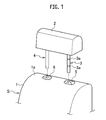
- a seat S includes a seat back 1, a headrest 2 that can hold the head of an occupant (not illustrated) from the backside, and cylindrical headrest stays 3 and 4 made of metal.
- the headrest 2 is supported on a top portion 1a of the seat back 1.
- the headrest stays 3 and 4 extend down from the headrest 2.
- a plurality of engagement portions 3a are formed at an appropriate vertical interval in a groove shape along a direction perpendicular to the longitudinal direction of the headrest stay 3.
- the vertical interval of the engagement portions 3a is each range of adjustment for the vertical height of the headrest 2.
- portions equivalent to the engagement portions 3a are not formed.
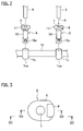
- a holder 5 and a holder 6 are disposed on the top portion 1a of the seat back 1, the holder 5 being a stay lock member that supports the one headrest stay 3, the holder 6 supporting the other headrest stay 4.
- the one holder 5 includes a cylinder portion 10, a flexible holder 14, a first head portion 9, an operation member 8, a coil spring 12, and a retaining rod 13.
- the other holder 6 includes the cylinder portion 10 and a second head portion 11.
- a stay insertion opening 7 is formed in each of the first head portion 9 and the second head portion 11.
- the cylinder portion 10 is integrally formed of a synthetic resin, and includes a body 10c which can be inserted in a holder bracket 1c which is supported by the frame of the seat back 1, an engagement portion 10a which is engageable with a lower end 1ca of the holder bracket 1c, an insertion opening 10b through which the headrest stay 3 is vertically movable smoothly, and a flange 10d which is formed in a brim shape at the upper end of the body 10c.
- the insertion opening 10b is through from the upper end to the lower end of the body 10c As illustrated in Figs.
- a conical hole 10e is provided that has an inclined surface 10f which is inclined inwardly from the upper end to the lower end (in other words, the diameter is tapered toward the lower end).
- nail portions 14a (described later) of the flexible holder 14 are housed.
- the inclined surface 10f of the conical hole 10e is such that as the flexible holder 14 enters deeper (in other words, is located in the downward direction) into the conical hole 10e, the width of the nail portions 14a is narrowed (in other words, the nail portions 14a are bent in the direction toward the center of the conical hole 10e).
- the flexible holder 14 is integrally formed of a synthetic resin.
- the flexible holder 14 is formed in a ring shape through which the headrest stay 3 is vertically movable smoothly and has the brim-shaped flange 14d which can be retained at the upper end of the cylinder portion 10 to prevent further descent.
- tow positioning bars 14c with which the operation member 8 is to be engaged, are formed, and 12 reed-shaped nail portions 14a are formed which extend down from the flange 14d.
- a guide face 15 having an inclined face is formed on the undersurface of the flange 14d.
- a retaining portion 14b is formed on the inner side of the lowest end of each nail portion 14a.
- the retaining portion 14b is engageable with the engagement portions 3a which are formed on the circumferential surface of the headrest stay 3.
- the flexible holder 14 is formed of a synthetic resin in the above description, but may be formed of a spring steel.
- the nail portion 14a may be formed of any material as long as the nail portion 14a has spring performance.
- the first head portion 9 is integrally formed of a synthetic resin.
- the stay insertion opening 7, through which the headrest stay 3 can be inserted, is formed in the upper surface of the first head portion 9.
- An opening is formed in the lower side and one of lateral sides.
- the operation member 8 and the flexible holder 14 are preassembled then fitted in the first head portion 9 through an opening in the lower side.
- the operation member 8 is inserted in the opening which is formed in one of the lateral sides, in a substantially horizontal direction in a freely advanceable and retreatable manner.
- a first projection portion 8a is formed in the other of the lateral sides.
- a second projection portion 9a is formed at a position opposed to the first projection portion 8a of the operation member 8 with the operation member 8 inserted in the first head portion 9.
- a coil spring 12 is press-fitted between the first projection portion 8a and the second projection portions 9a to constantly urge the operation member 8 in the right direction of Fig. 4 .
- the retaining rod 13 is supported by the operation member 8 so that the retaining rod 13 is engageable with each engagement portion 3a of the headrest stay 3.
- the nail portions 14a of the flexible holder 14 and the retaining rod 13 are both engageable with the engagement portion 3a of the headrest stay 3.
- the nail portions 14a of the flexible holder 14 may be in pressure contact with the circumferential surface of the headrest stay 3 and the retaining rod 13 may be engageable with the engagement portion 3a of the headrest stay 3.
- the first head portion 9 and the operation member 8 are supported such that the operation member 8 is constantly pressed by the coil spring 12 and protrudes from the first head portion 9 by dimension L as illustrated in Fig. 6 .
- the operation member 8 is movable by pressing the operation member 8 as indicated by black arrow F until the dimension L becomes zero.
- the operation member 8 has a through hole 8c through which the headrest stay 3 is penetrable and which escapes from the headrest stay 3 by a movement margin of the operation member 8.
- the operation member 8 includes a button 8e via which the operation member 8 is pressed.
- operation of the operation member 8 in a release direction allows a first pressing member 8b and a second pressing member 8d of the operation member 8 to lift up the guide surface 15 of the flexible holder 14.
- the flexible holder 14 is moved upward from the position of Fig. 4 by distance H as indicated by white arrow of Fig. 5 .
- the inside diameter of the nail portions 14a of the flexible holder 14 increases toward the outer side due to gradual release of inward forcing by the inclined surface 10f of the conical hole 10e. Then, the sliding resistance between the nail portions 14a of the flexible holder 14 and the circumferential surface of the headrest stay 3 decreases.
- the nail portions 14a of the flexible holder 14 are separated from the circumferential surface of the headrest stay 3 and play occurs between the nail portions 14a of the flexible holder 14 and the headrest stay 3, and no sliding resistance is present.
- the nail portions 14a of flexible holder 14 are separated from the engagement portion 3a of the headrest stay 3. Consequently, the sliding resistance of the headrest stay 3 decreases or disappears, and the operational force is reduced, which allows upward and downward movement of the headrest stay 3.
- the nail portions 14a are surely separated from the engagement portion 3a of the headrest stay 3, which provides good handleability of the headrest stay 3 for vertical position adjustment.
- the headrest stay 4 and the holder 6 have originally no sliding resistance therebetween.
- the urging force of the coil spring 12 causes the flexible holder 14 to move downward.
- the nail portions 14a of the flexible holder 14 are forced to be bent inwardly by the inclined surface 10f of the conical hole 10e, and the inside diameter decreases.
- the nail portions 14a of the flexible holder 14 come into contact with the circumferential surface of the headrest stay 3, and thus the sliding resistance between the nail portions 14a of the flexible holder 14 and the circumferential surface of the headrest stay 3 increases.
- the nail portions 14a of the flexible holder 14 are engaged with the engagement portion 3a of the headrest stay 3, and no play is provided between the nail portions 14a of the flexible holder 14 and the headrest stay 3.
- the nail portion 14a is engaged with the engagement portion 3a of the headrest stay 3 to tighten the headrest stay 3 around the circumferential surface. Consequently, upward and downward movement of the headrest stay 3 is prevented and no play is provided between parts, and thereby no backlash sound occurs.
- the nail portions 14a are surely separated from the engagement portion 3a of the headrest stay 3, which provides good handleability of the headrest stay 3 for upward and downward movement.
Landscapes
- Engineering & Computer Science (AREA)
- Aviation & Aerospace Engineering (AREA)
- Transportation (AREA)
- Mechanical Engineering (AREA)
- Seats For Vehicles (AREA)
- Chair Legs, Seat Parts, And Backrests (AREA)
Abstract
A holder (5) includes a stay lock member (8, 14) capable of locking a vertical movement of a headrest stay (3) at an appropriate vertical position by engaging with an engagement portion (3a) of the headrest stay (3). The stay lock member (8, 14) includes a flexible holder (14) having a nail portion (14a) engageable with the engagement portion (3a) along a circumferential direction of the headrest stay (3) as the flexible holder (14) moves in a lower direction and separable from the engagement portion (3a) as the flexible holder (14) moves in an upper direction, and an operation member (8) capable of moving the flexible holder (14) in any of the upper and lower directions.
Description
- The present invention relates to a seat for a vehicle, particularly, to a structure of a headrest support portion of a seat for a vehicle.
- There is a headrest support device as a structure that holds a headrest of a seat mounted in a vehicle, for instance, an automobile at a certain position in a vertical direction. This headrest support device can be reliably stopped at the certain position in the vertical direction, and has low sliding resistance in order to be movable either upward or downward. Also,
Patent Literature 1 proposes a headrest support device in which play is provided between parts so as to absorb a manufacturing error. - Patent Literature 1: Japanese Patent No.
3316839 - In such related arts, if large play is provided between parts, parts in the headrest support device may hit each other and cause hitting sound (also called backlash sound) as the automobile runs. On the other hand, if small play is provided between parts, the sliding resistance is so high that handleability of the headrest for vertical position adjustment is poor.
- It is an object of the present invention to provide a seat for a vehicle which has good handleability of a headrest for vertical position adjustment and in which no backlash sound occurs.
- A seat for a vehicle in accordance with some embodiments includes: a seat back including a frame; a holder bracket supported by the frame; a headrest; a headrest stay extending downward from a lower end of the headrest and being engaged with and supported by the holder bracket, the headrest stay having an engagement portion formed along a direction perpendicular to a longitudinal direction of the headrest stay; and a holder supporting the headrest stay inserted in the holder. The holder includes a stay lock member capable of locking a vertical movement of the headrest stay at an appropriate vertical position by engaging with the engagement portion of the headrest stay. The stay lock member includes a flexible holder having a nail portion engageable with the engagement portion of the headrest stay along a circumferential direction of the headrest stay as the flexible holder moves in a lower direction and separable from the engagement portion of the headrest stay as the flexible holder moves in an upper direction, and an operation member capable of moving the flexible holder in any of the upper and lower directions.
- According to the above-described configuration, operation of the operation member in a release direction causes the flexible holder to move upward and the nail portion is separated from the engagement portion of the headrest stay. Therefore, no sliding resistance of the headrest stay occurs, which provides good handleability of the headrest stay for vertical position adjustment. In addition, operation of the operation member in a stop direction causes the flexible holder to move downward, and the nail portion is engaged with the engagement portion of the headrest stay to tighten the headrest stay around the circumferential surface. Consequently, upward and downward movement of the headrest stay is prevented and no play is provided between parts, and thereby no backlash sound occurs. Thus, a seat for a vehicle with good marketability can be achieved.
- The holder may include a conical hole housing the nail portion of the flexible holder, and the conical hole may have an inclined surface bending the nail portion in a direction toward a center of the conical hole in response to a movement of the flexible holder in the lower direction.
- According to the above-described configuration, by moving the flexible holder in upward and downward directions, the headrest stay can switch between a movable state and a fixed state.
- The nail portion of the flexible holder may be constantly urged in a direction away from the circumferential surface of the headrest stay.
- According to the above-described configuration, only by moving the flexible holder upward, the nail portion is surely separated from the engagement portion of the headrest stay, which provides good handleability of the headrest stay for upward and downward movement.
-
-
Fig. 1 is a perspective view of a seat back of a seat illustrating a state where a headrest removed from a seat for a vehicle according to an embodiment of the present invention and an engagement portion of a headrest stay. -
Fig. 2 is an exploded perspective view of a supporting device of the headless stay ofFig. 1 . -
Fig. 3 is a top view of a holder seen along arrow A ofFig. 2 . -
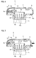
Fig. 4 is a cross-sectional view along line SB-SB ofFig. 3 . -
Fig. 5 is a cross-sectional view illustrating a state where a flexible holder is moved upward by pushing in an operation member ofFig. 4 . -
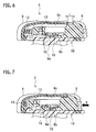
Fig. 6 is a cross-sectional view along line SC-SC ofFig. 3 . -
Fig. 7 is a cross-sectional view illustrating a means that causes a flexible holder to move upward by pushing in the operation member ofFig. 4 . -
Fig. 8 is an exploded perspective view of the headrest supporting device illustrated inFigs. 1 to 7 . -
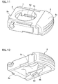
Fig. 9 is a perspective view of the flexible holder illustrated inFigs. 1 to 7 . -
Fig. 10 is a perspective view of the flexible holder ofFig. 9 , the view seen from the lower side. -
Fig. 11 is an enlarged perspective view of the operation member ofFig. 8 . -
Fig. 12 is an enlarged perspective view of the operation member ofFig. 11 , the view seen from the lower side. - The object of providing a seat for a vehicle, which has good handleability of a headrest for vertical position adjustment and in which no backlash sound occurs, has been achieved by the following configuration. Specifically, a seat for a vehicle includes: a seat back including a frame; a holder bracket supported by the frame; a headrest; a headrest stay extending downward from a lower end of the headrest and being engaged with and supported by the holder bracket, the headrest stay having an engagement portion formed along a direction perpendicular to a longitudinal direction of the headrest stay; and a holder supporting the headrest stay inserted in the holder. The holder includes a stay lock member capable of locking a vertical movement of the headrest stay at an appropriate vertical position by engaging with the engagement portion of the headrest stay. The stay lock member includes a flexible holder having a nail portion engageable with the engagement portion of the headrest stay along a circumferential direction of the headrest stay as the flexible holder moves in a lower direction and separable from the engagement portion of the headrest stay as the flexible holder moves in an upper direction, and an operation member capable of moving the flexible holder in any of the upper and lower directions..
- Hereinafter, a vehicle according to an embodiment of the present invention will be described based on
Fig. 1 to Fig. 12 . The configuration of a seat disposed in a vehicle, for instance, an automobile according to an embodiment of the present invention will be described. - A seat S includes a seat back 1, a
headrest 2 that can hold the head of an occupant (not illustrated) from the backside, and cylindrical headrest stays 3 and 4 made of metal. Theheadrest 2 is supported on atop portion 1a of the seat back 1. The headrest stays 3 and 4 extend down from theheadrest 2. In the one headrest stay 3, a plurality ofengagement portions 3a are formed at an appropriate vertical interval in a groove shape along a direction perpendicular to the longitudinal direction of the headrest stay 3. The vertical interval of theengagement portions 3a is each range of adjustment for the vertical height of theheadrest 2. In the other headrest stay 4, portions equivalent to theengagement portions 3a are not formed. - A
holder 5 and aholder 6 are disposed on thetop portion 1a of the seat back 1, theholder 5 being a stay lock member that supports the one headrest stay 3, theholder 6 supporting the other headrest stay 4. - The one
holder 5 includes acylinder portion 10, aflexible holder 14, afirst head portion 9, anoperation member 8, acoil spring 12, and aretaining rod 13. Theother holder 6 includes thecylinder portion 10 and asecond head portion 11. Astay insertion opening 7 is formed in each of thefirst head portion 9 and thesecond head portion 11. - The
cylinder portion 10 is integrally formed of a synthetic resin, and includes a body 10c which can be inserted in aholder bracket 1c which is supported by the frame of theseat back 1, anengagement portion 10a which is engageable with a lower end 1ca of theholder bracket 1c, an insertion opening 10b through which the headrest stay 3 is vertically movable smoothly, and aflange 10d which is formed in a brim shape at the upper end of the body 10c. The insertion opening 10b is through from the upper end to the lower end of the body 10c
As illustrated inFigs. 4, 5 , on the upper end side of the insertion opening 10b of thecylinder portion 10, aconical hole 10e is provided that has aninclined surface 10f which is inclined inwardly from the upper end to the lower end (in other words, the diameter is tapered toward the lower end). In theconical hole 10e,nail portions 14a (described later) of theflexible holder 14 are housed. Theinclined surface 10f of theconical hole 10e is such that as theflexible holder 14 enters deeper (in other words, is located in the downward direction) into theconical hole 10e, the width of thenail portions 14a is narrowed (in other words, thenail portions 14a are bent in the direction toward the center of theconical hole 10e). - The
flexible holder 14 is integrally formed of a synthetic resin. Theflexible holder 14 is formed in a ring shape through which the headrest stay 3 is vertically movable smoothly and has the brim-shaped flange 14d which can be retained at the upper end of thecylinder portion 10 to prevent further descent. In theflange 14d,tow positioning bars 14c, with which theoperation member 8 is to be engaged, are formed, and 12 reed-shaped nail portions 14a are formed which extend down from theflange 14d. On the undersurface of theflange 14d, aguide face 15 having an inclined face is formed. Aretaining portion 14b is formed on the inner side of the lowest end of eachnail portion 14a. The retainingportion 14b is engageable with theengagement portions 3a which are formed on the circumferential surface of theheadrest stay 3. Theflexible holder 14 is formed of a synthetic resin in the above description, but may be formed of a spring steel. In short, thenail portion 14a may be formed of any material as long as thenail portion 14a has spring performance. - The
first head portion 9 is integrally formed of a synthetic resin. Thestay insertion opening 7, through which theheadrest stay 3 can be inserted, is formed in the upper surface of thefirst head portion 9. An opening is formed in the lower side and one of lateral sides. Theoperation member 8 and theflexible holder 14 are preassembled then fitted in thefirst head portion 9 through an opening in the lower side. Theoperation member 8 is inserted in the opening which is formed in one of the lateral sides, in a substantially horizontal direction in a freely advanceable and retreatable manner. In the other of the lateral sides, afirst projection portion 8a is formed. Asecond projection portion 9a is formed at a position opposed to thefirst projection portion 8a of theoperation member 8 with theoperation member 8 inserted in thefirst head portion 9. Acoil spring 12 is press-fitted between thefirst projection portion 8a and thesecond projection portions 9a to constantly urge theoperation member 8 in the right direction ofFig. 4 . - The retaining
rod 13 is supported by theoperation member 8 so that the retainingrod 13 is engageable with eachengagement portion 3a of theheadrest stay 3. Thenail portions 14a of theflexible holder 14 and the retainingrod 13 are both engageable with theengagement portion 3a of theheadrest stay 3. However, thenail portions 14a of theflexible holder 14 may be in pressure contact with the circumferential surface of theheadrest stay 3 and the retainingrod 13 may be engageable with theengagement portion 3a of theheadrest stay 3. - The
first head portion 9 and theoperation member 8 are supported such that theoperation member 8 is constantly pressed by thecoil spring 12 and protrudes from thefirst head portion 9 by dimension L as illustrated inFig. 6 . As illustrated inFig. 5 andFig. 7 , theoperation member 8 is movable by pressing theoperation member 8 as indicated by black arrow F until the dimension L becomes zero. - The
operation member 8 has a throughhole 8c through which theheadrest stay 3 is penetrable and which escapes from theheadrest stay 3 by a movement margin of theoperation member 8. Theoperation member 8 includes abutton 8e via which theoperation member 8 is pressed. - The effect of the embodiment of the present invention will be described below.
- As indicated by black arrow F illustrated in
Fig. 5 andFig. 7 , operation of theoperation member 8 in a release direction allows a first pressingmember 8b and a second pressingmember 8d of theoperation member 8 to lift up theguide surface 15 of theflexible holder 14. Thus, theflexible holder 14 is moved upward from the position ofFig. 4 by distance H as indicated by white arrow ofFig. 5 . As theflexible holder 14 is moved upward, the inside diameter of thenail portions 14a of theflexible holder 14 increases toward the outer side due to gradual release of inward forcing by theinclined surface 10f of theconical hole 10e. Then, the sliding resistance between thenail portions 14a of theflexible holder 14 and the circumferential surface of theheadrest stay 3 decreases. Finally, thenail portions 14a of theflexible holder 14 are separated from the circumferential surface of theheadrest stay 3 and play occurs between thenail portions 14a of theflexible holder 14 and theheadrest stay 3, and no sliding resistance is present. At this point, thenail portions 14a offlexible holder 14 are separated from theengagement portion 3a of theheadrest stay 3. Consequently, the sliding resistance of theheadrest stay 3 decreases or disappears, and the operational force is reduced, which allows upward and downward movement of theheadrest stay 3. In this manner, only by moving theflexible holder 14 upward, thenail portions 14a are surely separated from theengagement portion 3a of theheadrest stay 3, which provides good handleability of theheadrest stay 3 for vertical position adjustment. Theheadrest stay 4 and theholder 6 have originally no sliding resistance therebetween. - Also, in a state (half locked state) where the retaining
rod 13 is separated from theengagement portion 3a and theflexible holder 14 and theheadrest stay 3 are in contact with each other, the sliding resistance between theflexible holder 14 and theheadrest stay 3 is low, and thus theheadrest 2 is movable upward and downward to the position of theengagement portion 3a of theheadrest stay 3. - Also, with an operation of the
operation member 8 in a stop direction, that is, with an operation not in the direction of black arrow F, the urging force of thecoil spring 12 causes theflexible holder 14 to move downward. When theflexible holder 14 is moved downward, thenail portions 14a of theflexible holder 14 are forced to be bent inwardly by theinclined surface 10f of theconical hole 10e, and the inside diameter decreases. Then, thenail portions 14a of theflexible holder 14 come into contact with the circumferential surface of theheadrest stay 3, and thus the sliding resistance between thenail portions 14a of theflexible holder 14 and the circumferential surface of theheadrest stay 3 increases. Finally, thenail portions 14a of theflexible holder 14 are engaged with theengagement portion 3a of theheadrest stay 3, and no play is provided between thenail portions 14a of theflexible holder 14 and theheadrest stay 3. At this point, thenail portion 14a is engaged with theengagement portion 3a of theheadrest stay 3 to tighten theheadrest stay 3 around the circumferential surface. Consequently, upward and downward movement of theheadrest stay 3 is prevented and no play is provided between parts, and thereby no backlash sound occurs. - Also, only by moving the
flexible holder 14 upward, thenail portions 14a are surely separated from theengagement portion 3a of theheadrest stay 3, which provides good handleability of theheadrest stay 3 for upward and downward movement. - Although the embodiment of the present invention has been described in the above, the present invention is not limited to the above-described embodiment and various modifications are possible.
Claims (3)
- A seat for a vehicle, comprising:a seat back including a frame;a holder bracket supported by the frame;a headrest;a headrest stay extending downward from a lower end of the headrest and being engaged with and supported by the holder bracket, the headrest stay having an engagement portion formed along a direction perpendicular to a longitudinal direction of the headrest stay; anda holder supporting the headrest stay inserted in the holder,wherein the holder includes a stay lock member capable of locking a vertical movement of the headrest stay at an appropriate vertical position by engaging with the engagement portion of the headrest stay, andwherein the stay lock member includes
a flexible holder having a nail portion engageable with the engagement portion of the headrest stay along a circumferential direction of the headrest stay as the flexible holder moves in a lower direction and separable from the engagement portion of the headrest stay as the flexible holder moves in an upper direction, and
an operation member capable of moving the flexible holder in any of the upper and lower directions. - The seat for a vehicle according to claim 1, wherein
the holder includes a conical hole housing the nail portion of the flexible holder, and
the conical hole has an inclined surface bending the nail portion in a direction toward a center of the conical hole in response to a movement of the flexible holder in the lower direction. - The seat for a vehicle according to claim 1, wherein the nail portion of the flexible holder is constantly urged in a direction away from the circumferential surface of the headrest stay.
Applications Claiming Priority (1)
| Application Number | Priority Date | Filing Date | Title |
|---|---|---|---|
| PCT/JP2013/059266 WO2014155606A1 (en) | 2013-03-28 | 2013-03-28 | Seat for vehicle |
Publications (1)
| Publication Number | Publication Date |
|---|---|
| EP2979583A1 true EP2979583A1 (en) | 2016-02-03 |
Family
ID=51622680
Family Applications (1)
| Application Number | Title | Priority Date | Filing Date |
|---|---|---|---|
| EP13880007.3A Withdrawn EP2979583A1 (en) | 2013-03-28 | 2013-03-28 | Seat for vehicle |
Country Status (4)
| Country | Link |
|---|---|
| US (1) | US20160052430A1 (en) |
| EP (1) | EP2979583A1 (en) |
| JP (1) | JP6031185B2 (en) |
| WO (1) | WO2014155606A1 (en) |
Families Citing this family (5)
| Publication number | Priority date | Publication date | Assignee | Title |
|---|---|---|---|---|
| JP6513967B2 (en) * | 2015-02-26 | 2019-05-15 | 日本発條株式会社 | Headrest device |
| KR101793159B1 (en) * | 2016-07-26 | 2017-11-03 | 주식회사 대유홀딩스 | Stepless height controlling device of headrest for car seat |
| KR101836794B1 (en) * | 2016-10-26 | 2018-03-09 | 주식회사 다스 | Guiding device for stay rod for headrest of seat |
| JP6922610B2 (en) * | 2017-09-27 | 2021-08-18 | トヨタ紡織株式会社 | Seat back frame |
| DE102023115519A1 (en) * | 2023-06-14 | 2024-12-19 | Grammer Aktiengesellschaft | Storage facility, guide arrangement and equipment part of a vehicle interior |
Family Cites Families (9)
| Publication number | Priority date | Publication date | Assignee | Title |
|---|---|---|---|---|
| JPS56140350U (en) * | 1980-03-24 | 1981-10-23 | ||
| JPH0531979Y2 (en) * | 1988-11-18 | 1993-08-17 | ||
| JP3316839B2 (en) * | 1997-04-28 | 2002-08-19 | ジョンソン コントロールズ オートモーティブ システムズ株式会社 | Headrest stay support structure |
| JP3513646B2 (en) * | 1998-09-29 | 2004-03-31 | 株式会社パイオラックス | Headrest support structure |
| US7309108B2 (en) * | 2004-11-22 | 2007-12-18 | Tachi-S Co., Ltd. | Headrest device for vehicle seat |
| JP4336358B2 (en) * | 2006-08-23 | 2009-09-30 | 矢崎総業株式会社 | Connector unit |
| US7789465B2 (en) * | 2008-01-11 | 2010-09-07 | Honda Motor Co., Ltd. | Headrest adjustment and lock mechanism and method |
| WO2009142063A1 (en) * | 2008-05-22 | 2009-11-26 | 株式会社パイオラックス | Headrest support device for automobile seat |
| JP5243381B2 (en) * | 2009-10-05 | 2013-07-24 | 三協株式会社 | Headrest support device |
-
2013
- 2013-03-28 US US14/780,308 patent/US20160052430A1/en not_active Abandoned
- 2013-03-28 EP EP13880007.3A patent/EP2979583A1/en not_active Withdrawn
- 2013-03-28 JP JP2015507803A patent/JP6031185B2/en active Active
- 2013-03-28 WO PCT/JP2013/059266 patent/WO2014155606A1/en not_active Ceased
Non-Patent Citations (1)
| Title |
|---|
| See references of WO2014155606A1 * |
Also Published As
| Publication number | Publication date |
|---|---|
| JP6031185B2 (en) | 2016-11-24 |
| WO2014155606A1 (en) | 2014-10-02 |
| US20160052430A1 (en) | 2016-02-25 |
| JPWO2014155606A1 (en) | 2017-02-16 |
Similar Documents
| Publication | Publication Date | Title |
|---|---|---|
| EP2979583A1 (en) | Seat for vehicle | |
| US9643566B2 (en) | Height adjuster of seat belt for vehicle | |
| KR100789890B1 (en) | Headrest coupling structure of car seat | |
| JP6272245B2 (en) | Anchor for seat belt device | |
| US9783083B2 (en) | Vehicle seat slide device | |
| US10173634B2 (en) | Seat mounted adjustable seat belt webbing guide | |
| US7807936B2 (en) | Device for mounting a pedal switch to a vehicle | |
| US10099589B2 (en) | Headrest guide | |
| US10266142B2 (en) | Automobile steering wheel | |
| JPWO2017183619A1 (en) | Component temporary holding member and component mounting jig | |
| US20160347260A1 (en) | Fuse-puller holding structure | |
| JP5875329B2 (en) | Sliding door retractor | |
| JP5911023B2 (en) | Resin member mounting structure | |
| KR20180070155A (en) | Pole-guide of head-rest | |
| JP2009299850A (en) | Clip mounting seat | |
| JP7293554B2 (en) | Anchor device | |
| KR200473252Y1 (en) | Insert molding producing apparatus | |
| JP5325455B2 (en) | Active headrest headrest tilting device | |
| JP2019072938A (en) | Component mounting jig | |
| CN109555763B (en) | Clamp mounting base | |
| KR20090128741A (en) | Pole guide for headrest | |
| US8240229B2 (en) | Shift lever device | |
| KR101464544B1 (en) | Steering system of automobile | |
| WO2015162785A1 (en) | Headrest support device and vehicle seat equipped with same | |
| JP2015077827A (en) | Vehicular steering apparatus |
Legal Events
| Date | Code | Title | Description |
|---|---|---|---|
| PUAI | Public reference made under article 153(3) epc to a published international application that has entered the european phase |
Free format text: ORIGINAL CODE: 0009012 |
|
| 17P | Request for examination filed |
Effective date: 20151005 |
|
| AK | Designated contracting states |
Kind code of ref document: A1 Designated state(s): AL AT BE BG CH CY CZ DE DK EE ES FI FR GB GR HR HU IE IS IT LI LT LU LV MC MK MT NL NO PL PT RO RS SE SI SK SM TR |
|
| AX | Request for extension of the european patent |
Extension state: BA ME |
|
| STAA | Information on the status of an ep patent application or granted ep patent |
Free format text: STATUS: THE APPLICATION HAS BEEN WITHDRAWN |
|
| 18W | Application withdrawn |
Effective date: 20160310 |