EP2978495B1 - Accessory holder for particle beam apparatus - Google Patents
Accessory holder for particle beam apparatus Download PDFInfo
- Publication number
- EP2978495B1 EP2978495B1 EP14715233.4A EP14715233A EP2978495B1 EP 2978495 B1 EP2978495 B1 EP 2978495B1 EP 14715233 A EP14715233 A EP 14715233A EP 2978495 B1 EP2978495 B1 EP 2978495B1
- Authority
- EP
- European Patent Office
- Prior art keywords
- accessory
- nozzle
- interface
- displacement means
- movable portion
- Prior art date
- Legal status (The legal status is an assumption and is not a legal conclusion. Google has not performed a legal analysis and makes no representation as to the accuracy of the status listed.)
- Active
Links
Images




Classifications
-
- A—HUMAN NECESSITIES
- A61—MEDICAL OR VETERINARY SCIENCE; HYGIENE
- A61N—ELECTROTHERAPY; MAGNETOTHERAPY; RADIATION THERAPY; ULTRASOUND THERAPY
- A61N5/00—Radiation therapy
- A61N5/10—X-ray therapy; Gamma-ray therapy; Particle-irradiation therapy
- A61N5/1077—Beam delivery systems
- A61N5/1083—Robot arm beam systems
-
- A—HUMAN NECESSITIES
- A61—MEDICAL OR VETERINARY SCIENCE; HYGIENE
- A61N—ELECTROTHERAPY; MAGNETOTHERAPY; RADIATION THERAPY; ULTRASOUND THERAPY
- A61N5/00—Radiation therapy
- A61N5/10—X-ray therapy; Gamma-ray therapy; Particle-irradiation therapy
- A61N5/1042—X-ray therapy; Gamma-ray therapy; Particle-irradiation therapy with spatial modulation of the radiation beam within the treatment head
-
- A—HUMAN NECESSITIES
- A61—MEDICAL OR VETERINARY SCIENCE; HYGIENE
- A61N—ELECTROTHERAPY; MAGNETOTHERAPY; RADIATION THERAPY; ULTRASOUND THERAPY
- A61N5/00—Radiation therapy
- A61N5/10—X-ray therapy; Gamma-ray therapy; Particle-irradiation therapy
- A61N5/1042—X-ray therapy; Gamma-ray therapy; Particle-irradiation therapy with spatial modulation of the radiation beam within the treatment head
- A61N5/1043—Scanning the radiation beam, e.g. spot scanning or raster scanning
-
- A—HUMAN NECESSITIES
- A61—MEDICAL OR VETERINARY SCIENCE; HYGIENE
- A61N—ELECTROTHERAPY; MAGNETOTHERAPY; RADIATION THERAPY; ULTRASOUND THERAPY
- A61N5/00—Radiation therapy
- A61N5/10—X-ray therapy; Gamma-ray therapy; Particle-irradiation therapy
- A61N5/1077—Beam delivery systems
-
- A—HUMAN NECESSITIES
- A61—MEDICAL OR VETERINARY SCIENCE; HYGIENE
- A61N—ELECTROTHERAPY; MAGNETOTHERAPY; RADIATION THERAPY; ULTRASOUND THERAPY
- A61N5/00—Radiation therapy
- A61N5/10—X-ray therapy; Gamma-ray therapy; Particle-irradiation therapy
- A61N5/1048—Monitoring, verifying, controlling systems and methods
- A61N2005/1074—Details of the control system, e.g. user interfaces
-
- A—HUMAN NECESSITIES
- A61—MEDICAL OR VETERINARY SCIENCE; HYGIENE
- A61N—ELECTROTHERAPY; MAGNETOTHERAPY; RADIATION THERAPY; ULTRASOUND THERAPY
- A61N5/00—Radiation therapy
- A61N5/10—X-ray therapy; Gamma-ray therapy; Particle-irradiation therapy
- A61N2005/1085—X-ray therapy; Gamma-ray therapy; Particle-irradiation therapy characterised by the type of particles applied to the patient
- A61N2005/1087—Ions; Protons
-
- A—HUMAN NECESSITIES
- A61—MEDICAL OR VETERINARY SCIENCE; HYGIENE
- A61N—ELECTROTHERAPY; MAGNETOTHERAPY; RADIATION THERAPY; ULTRASOUND THERAPY
- A61N5/00—Radiation therapy
- A61N5/10—X-ray therapy; Gamma-ray therapy; Particle-irradiation therapy
- A61N2005/1092—Details
- A61N2005/1095—Elements inserted into the radiation path within the system, e.g. filters or wedges
Definitions
- the invention is related to installations for particle beam treatment, such as proton therapy, wherein a tumor is irradiated with a proton beam.
- the invention is particularly related to an accessory holder attachable to the nozzle of a particle beam apparatus.
- Pencil Beam scanning a proton beam produced by a radiation source, such as a cyclotron, is targeted at subsequent points within subsequent layers of the treated tumor.
- a radiation source such as a cyclotron
- Each layer of the tumor is thereby 'scanned' (also referred to as 'painted') by a beam, the beam intensity for points in each layer controlled to deliver the prescribed dose at the point in question.
- This technique represents an advance over single or double scattering techniques, wherein a scattered beam is shaped by a patient specific collimator, so that it corresponds to the shape of the treated tumor.
- PBS does not require the expensive and heavy patient specific collimator
- specific accessories such as a ridge filter, a range compensator or range shifter, or an aperture for improving the lateral penumbra or for sparing organs at risk that are situated close to the treated tumor, may need to be placed in the path of the beam between the nozzle and the target before or during a scanning treatment.
- These accessories need to be mounted and removed manually, which leads to a considerable loss of time and efficiency of the treatment installation.
- the present invention is related to an accessory holder attachable to or integrated in the nozzle of an apparatus for particle beam irradiation treatment.
- the accessory may be an aperture piece, a range shifter, or any other element that can be placed in the beam path between the outer end of the nozzle and the irradiated target.
- the accessory holder is equipped with first displacement means for moving the accessory away from or towards the nozzle, thereby moving the accessory forwards and backwards in the direction of the beam, and second displacement means for moving the accessory into or out of the beam path. Measurements or treatment steps can thus be performed with and without the accessory in the beam path, without interrupting the treatment.
- the first displacement means comprises an eccentrically placed axle equipped with actuator arms that are designed to actuate a linear movement of support rods that support the second displacement means, the latter comprising a slidable drawer into which the accessory can be inserted.
- the invention is related to an accessory holder, a particle beam irradiation apparatus and a method as disclosed in the appended claims.
- the invention is thus related to an accessory holder for a particle beam treatment apparatus comprising a nozzle for delivering a beam to a target, said holder being connectable to or integrated in said nozzle, the holder comprising:
- said first displacement means comprises a first movable portion configured to move in said first direction with respect to the nozzle
- the second displacement means comprises a second movable portion configured to move in said second direction with respect to said first movable portion
- the second movable portion comprises said accessory interface
- said second displacement means comprises a second movable portion, configured to move in said second direction with respect to the nozzle and wherein the first displacement means comprises a first movable portion configured to move in said first direction with respect to said second movable portion, and wherein the first movable portion comprises said accessory interface.
- the first displacement means does not comprise an expansion and contraction section having a bellows shape.
- said movement in the second direction, into or out of the path of the beam is a linear translational movement such as the sliding of a tray that can be moved into or out of the beam path.
- the first displacement means may further comprise a rotatable axle provided with actuator arms configured to move the first movable portion along said first direction away from or towards the nozzle.
- the second movable portion may comprise a slidable drawer configured to slide back and forth in said second direction, said drawer comprising said interface to receive and secure an accessory.
- An accessory holder according to the invention may comprise a base portion connectable to said nozzle, with said first or second displacement means being mounted on said base portion.
- said accessory holder comprising a base portion connectable to said nozzle, with said first or second displacement means being mounted on said base portion, said first displacement means further comprises support pieces and support rods attached at one end to said support pieces and supporting the first movable portion at the other end, the base portion comprising guide holes into which said rods are inserted, and wherein said arms are provided with elongate openings, configured to slidably receive cylindrical ends of said support pieces, so that rotation of said arms actuates a linear movement of said support rods
- the first and second displacement means are motorized and actuatable from a distance, i.e. without requiring manual manipulation of the movable portions of the displacement means.
- the first and/or second displacement means may comprise electrical and/or pneumatic drive means.
- said first direction is the direction of a first linear path
- the wherein the second direction is the direction of a second linear path perpendicular to the first linear path
- the invention is equally related to a particle beam apparatus comprising an irradiation source and a nozzle, with an accessory holder according to the invention mounted on or incorporated in said nozzle.
- Said apparatus may comprise a particle beam scanning device for scanning a particle beam over a target.
- the apparatus comprises a snout attachable to said accessory holder and whereby said snout is further configured for holding one or more accessories such as an aperture, a range compensator, a ridge filter or a range shifter.
- the invention is equally related to a method for positioning an accessory in a particle beam treatment apparatus comprising a nozzle for delivering a beam to a target and an accessory holder connected to or integrated in said nozzle, said holder comprising:
- said movements may be actuated by automated drive means controlled by an operator, i.e. the movements are motorized and actuated from a distance. No manual manipulations are required during said movements.
- said accessory may be an aperture piece or a range shifter or a ridge filter for use with a Pencil Beam Scanning nozzle or wherein said accessory is a holding means holding such an aperture piece, range shifter or ridge filter.
- Figures 1 and 2 illustrate the basic structure of an accessory holder according to the invention.
- the holder 1 is attachable to the nozzle 2 of a particle beam installation.
- the nozzle is described as a Pencil Beam Scanning nozzle, even though the invention is not limited to this type of irradiation nozzle.
- the term nozzle refers to the last part in the sequence of parts, starting with the beam source, required to produce a scanning beam 3, directed at a target, such as a patient tumour 4.
- the nozzle is usually the part that comprises the dosimetry device for measuring the delivered dose.
- the nozzle comprises the scanning magnets for performing the pencil beam scanning.
- the scanning magnets for performing pencil beam scanning are installed more upstream in the beam line.
- the scanning magnets are installed upstream of the last bending magnet and the part downstream of the last bending magnet comprising the dosimetry device can be called the nozzle.
- the accessory holder 1 comprises a base portion 5 that is attached (e.g. bolted) to the nozzle 2.
- the base portion is preferably releasably attached to the nozzle. Nevertheless, the accessory holder of the invention can stay attached to the nozzle during a complete treatment process, and may need to be removed only in case of repairs or maintenance of the installation.
- the accessory holder is fully integrated in the nozzle. There is then no separate base portion as the function of this base portion (i.e. carrying the first and second displacement means) is fulfilled by the nozzle itself. In this case, the base portion is part of the overall nozzle frame.
- a first movable portion 6 is mounted on the base portion 5 and configured to be movable with respect to said base portion, in the Z-direction indicated in the drawing, i.e. closer to or away from the target 4.
- Support and/or guide elements 7 and a suitable power source (not shown) are provided for guiding and driving this movement.
- a second movable portion 8 is mounted on the first movable portion 6 and configured to be movable in the Y-direction, with respect to said first portion, the Y-direction being perpendicular to the Z-direction.
- An accessory 9 attached to the second movable portion 8 can thus be moved into and out of the beam path.
- Further driving means are provided for actuating this sideways movement.
- the second movable portion 8 is provided with an interface (not shown) configured for receiving an accessory 9 and holding the accessory during the movements along the Z and Y-axes.
- the interface can be a separate interface part attached to the movable portion 8 or it can be integrated in the movable portion 8.
- the interface can for example comprise a slot with a locking mechanism for inserting and removing an accessory 9 and for locking the accessory 9 to the second movable portion 8, so that during motion of the second movable portion 8, the accessory 9 remains attached to the second movable portion 8.
- the interface is preferably not designed to receive one particular type of accessory, but rather it is designed to receive any type of accessory that may need to be installed, such as a range shifter or an aperture.
- the interface comprises a rectangular receiving area provided in the movable portion (e.g.
- a drawer that is configured to move into or out of the beam path, said area being delimited by side beams, into which the accessory can be inserted by sliding the accessory into said area.
- Locking means such as pneumatically operated locking pins are then provided for maintaining the accessory in a fixed position with respect to the moveable portion.
- the accessory 9 remains attached to the second movable portion 8 in any position of said first and second movable portions. In this way, the accessory can be brought closer to the target and/or into and out of the beam path without removing it from the accessory holder as such. This capability allows to perform multiple irradiation steps with and without accessories in the beam path, without interrupting the treatment.
- a first movable portion 10 is movable in the Z-direction and provided with an interface (not shown) for receiving and holding the accessory 9.
- the first movable portion 10 is mounted on a second movable portion 11 and configured to move in the Z-direction with respect to said second movable portion 11.
- the second movable portion 11 is itself mounted on the base portion 5, and configured to be movable in the Y-direction, with respect to said base portion 5.
- Both embodiments shown in figure 1 and 2 are examples of how to bring the invention into practice. All of the described displacement means are motorized and actuatable from a distance, through the use of suitable drive and actuator means, such as electrical motors, pneumatic actuators or the like.
- the first embodiment shown in figure 1 is the preferred option as it allows the second movable portion 8, i.e. the portion that is slidable sideways with respect to the beam direction, to be produced in a manner that takes up a minimum of space in said beam direction, as will be illustrated in a detailed embodiment described further on.
- the second moveable portions 8 and 11 are preferably moveable by a linear translational movement, i.e. a movement along a straight line.
- the Z and Y directions are examples of the 'first' and 'second' direction referred to in the claims. Another way of referring to these directions may be 'longitudinal' and 'lateral' directions.
- the described movements in the Z-direction are examples of movements 'in the direction of a beam produced by the apparatus' referred to in the appended claims. Movements that are oriented at an angle to Z but according to which a movable portion still approaches towards or recedes away from the target, also qualify as said movements 'in the direction of a beam produced by the apparatus'.
- irradiation with and without an accessory in the beam path can be effected with the accessory remaining attached to the holder, and without interrupting the treatment or at least without manually adjusting the accessory.
- irradiations can be performed with the accessory at various positions in the direction of the beam path. For example, when shallow target volumes, i.e. target volumes close to the skin surface need to be treated, a range shifter needs to be installed in the beam line in order to further reduce the minimum energy of the particle therapy apparatus.
- a range shifter For example if the minimum energy of the particle therapy apparatus corresponds to a depth in the patient of 5 cm, and shallow tumours close to the skin surface need to be treated, then such a range shifter needs to be used to reduce the penetration depth of the beam with a few cm.
- a standard range shifter can be installed in the accessory holder and when a treatment requires the range shifting, the range shifter can be inserted when needed.
- this insert or extraction of a range shifter can be done without manual intervention of the radiotherapist. The motion can be actuated either from a control in the treatment room or from a control outside the treatment room.
- FIG. 3 shows a 3D view of the accessory holder 1 according to the invention, holding a circle-shaped aperture accessory 9.
- the blow-up view illustrates the main components.
- the base portion 5 is a box-shaped piece assembled from machined plates (e.g. steel). Support plates 20 are provided with holes 21 through which the base portion 5 can be bolted to the face of the nozzle (not shown). Bottom and top openings 22 and 23 are provided for allowing the passage of the particle beam.
- An axle 24, rotatable with respect to the base portion 5, passes through holes 25 in two opposite side walls of the base portion.
- the axle is eccentrically placed in the base portion, i.e. it is located laterally with respect to the base portion's center plane perpendicular to said opposite walls, in a position so that it is unable to block the beams passing through the openings 22/23.
- the axle's rotation in the two rotation directions is driven by an electric motor 26.
- two actuator arms 27 Fixed to the axle 24, i.e. rotating together with the axle, two actuator arms 27 are mounted, one on each side of the base portion 5.
- the actuator arms have elongate openings 28, configured to receive a cylindrical protrusion 29 of a support piece 30.
- a pair of cylindrical rods 35 is connected by inserting the rods into openings 37 of the support pieces and securing them by securing pins 38.
- the rods 35 are inserted in openings 39 provided in the upper surface of the base portion 5.
- the shape and dimensions of the elongate openings 28 and the protrusions 29 as well as their respective materials are selected such that rotation of the axle 24 actuates a linear movement of the rods 35 guided by the holes 39, through the movement of the protrusions 29 inside the elongate openings 28.
- the two extreme positions of this mechanism are shown in more detail in figures 4a and 4b .
- the shape of the two actuator arms 27 is different in this embodiment, as these arms have been designed to actuate the exact same movement of the rods 35, taking into account a torsional deformation of the axle 24.
- the set of four rods 35 supports the first movable portion 6 which is, in this embodiment, a flat rectangular frame attached to the end of the rods 35.
- the second movable portion is, in this embodiment, a slidable drawer 8 configured to move perpendicularly to the rods 35, driven by a pneumatic drive mechanism.
- Figures 5a and 5b show the two extreme positions of the drawer 8. The drawer is guided by lateral guides or rails 45 on the first movable portion 6.
- the drawer 8 comprises a rectangular receiving area delimited by side beams 46, into which the accessory can be inserted by sliding the accessory into said area.
- Pneumatically operated locking pins 47 are provided for maintaining the accessory in a fixed position with respect to the drawer 8.
- the interface is not a separate piece, but it is incorporated in the drawer itself (the second movable portion referred to in the claims).
- the element that is inserted into the drawer can be the aperture piece 9 shown in the drawings, or it can be a support element such as a tray or a snout, that is itself designed to carry the accessory, e.g. a range shifter. The support element is then designed to fit into the drawer, in the same way that is shown for the aperture piece 9.
- the drawer can move along the central beam direction away from or towards the nozzle over a distance of maximum 25 cm.
- the first displacement means for moving the accessory interface in a first direction allow for movement of the interface over a distance of more than 10 cm. More preferably, the first displacement means allow for movement of the interface over a distance of more than 20 cm.
- the accessory 9 can be an aperture, a range shifter, a ridge filter, a range compensator or any other type accessory. What is drawn as the accessory 9 in figures 1 and 2 can also be itself a means for holding other accessories such as an aperture piece, range shifter etc.
- Figure 6 illustrates an embodiment wherein the accessory 9 comprises a tray 55 configured for fitting in a slot of the interface 81 as illustrated in Figure 6a and Figure 6b . On the tray 55, a range shifter 53 or another accessory, such as a ridge filter or an aperture, can be attached.
- Figure 6b shows the tray 55 attached to the interface 81 of the accessory holder 1 whereby, in this illustration, the interface 81 of the accessory holder 1 is in a position out of a central beam path 3. In this example, the tray 55 fulfils the role of an accessory holding element.
- the accessory 9 comprises a snout 50 attachable to the interface 81 of the second movable portion 8.
- the snout 50 can for example be configured for fitting in a slot of the interface 81.
- the snout 50 itself is a structure having a base 100 and a protruding portion 101 provided at the end with a plurality of slots or other means into which accessories can be fitted.
- the snout thus allows to hold one or more accessories such as an aperture or a range compensator or a ridge filter or a range shifter.
- the snout 50 can for example comprise two slots (not shown on the figure) for receiving two accessories at the same time, for example an aperture and a range compensator.
- Figure 7a shows a snout 55 holding two accessories 51 and 52 which can for example be an aperture and a range compensator.
- Figure 7b shows the accessory holder 1 attached to a nozzle 2 whereby the snout 55 is positioned in a central beam path 3.
- Figure 7c shows the same snout 55 as in Figure 7b but in a geometry whereby the snout is positioned out of a central beam path 3 using the second movable portion 8 and whereby the snout is located closer to the nozzle when compared to Figure 7b by using the motion of the first movable portion 6.
- a snout 50 attaches to the accessory holder 1 to the accessory holder 1 to the accessory holder 1 to the accessory holder 1 .
- accessories aperture, range compensator, ridge filter, range shifter
- Figure 8 The advantage of attaching a snout 50 to the accessory holder 1 is that accessories (aperture, range compensator, ridge filter, range shifter) can be brought very close to the patient as illustrated in Figure 8 .
- a snout 50 with a small diameter is used so that the shoulder of the patient 90 is not in collision with the snout.
- a library of different snouts having different diameters will be available for the particle therapy apparatus.
- a library of three different snouts can comprise a first snout for holding circular accessories having a diameter up to 12 cm, a second snout for holding circular accessories having a diameter up to 20 cm and a third snout for holding accessories having a rectangular shape of for example 28 cm x 38 cm.
- corresponding accessories 51,52 of a given maximum diameter can be mounted on each snout 50.
- the snout 50 fulfils the role of an accessory holding element.
- displacement mechanisms may be used instead of the ones shown in the embodiment of figures 3 to 5 , for example a system comprising an extendable portion 6 that is movable on a set of rails, as it is known for supporting and moving a collimator closer to or away from the target in a double scattering installation.
- the displacement mechanism for movement in the direction of the beam does not comprise nor consist of a bellows-type mechanism.
- the mechanism comprising the actuator arms 27 and support rods 35 has however a specific advantage in that it is very compact in the direction of the beam. Given that the accessory holder must be able to further support and manipulate the second movable portion 8, this provides a maximum of movement space for the accessory.
- the invention therefore finds its primary use in PBS scanning installations, wherein a variety of accessories, including an aperture piece for, for example, sparing organs at risk, can be positioned with the holder of the invention.
Landscapes
- Health & Medical Sciences (AREA)
- Engineering & Computer Science (AREA)
- Biomedical Technology (AREA)
- Pathology (AREA)
- Nuclear Medicine, Radiotherapy & Molecular Imaging (AREA)
- Radiology & Medical Imaging (AREA)
- Life Sciences & Earth Sciences (AREA)
- Animal Behavior & Ethology (AREA)
- General Health & Medical Sciences (AREA)
- Public Health (AREA)
- Veterinary Medicine (AREA)
- Robotics (AREA)
- Radiation-Therapy Devices (AREA)
Description
- The invention is related to installations for particle beam treatment, such as proton therapy, wherein a tumor is irradiated with a proton beam. The invention is particularly related to an accessory holder attachable to the nozzle of a particle beam apparatus.
- In particle beam treatment, a number of irradiation techniques are known today. In Pencil Beam scanning (PBS) a proton beam produced by a radiation source, such as a cyclotron, is targeted at subsequent points within subsequent layers of the treated tumor. Each layer of the tumor is thereby 'scanned' (also referred to as 'painted') by a beam, the beam intensity for points in each layer controlled to deliver the prescribed dose at the point in question. This technique represents an advance over single or double scattering techniques, wherein a scattered beam is shaped by a patient specific collimator, so that it corresponds to the shape of the treated tumor.
- Even though PBS does not require the expensive and heavy patient specific collimator, specific accessories, such as a ridge filter, a range compensator or range shifter, or an aperture for improving the lateral penumbra or for sparing organs at risk that are situated close to the treated tumor, may need to be placed in the path of the beam between the nozzle and the target before or during a scanning treatment.. These accessories need to be mounted and removed manually, which leads to a considerable loss of time and efficiency of the treatment installation.
- Regardless of the irradiation technique used, means for holding accessories in the path of a beam between the nozzle and the target, with the possibility of approaching the target at a close distance, are generally lacking flexibility of use, both in terms of the available movements and their control and automation.
- The
U.S. Patent Application Publication 2012/0316378 A1 discloses such means for holding accessories in the path of a particle beam between the nozzle and the target. - The present invention is related to an accessory holder attachable to or integrated in the nozzle of an apparatus for particle beam irradiation treatment. The accessory may be an aperture piece, a range shifter, or any other element that can be placed in the beam path between the outer end of the nozzle and the irradiated target. The accessory holder is equipped with first displacement means for moving the accessory away from or towards the nozzle, thereby moving the accessory forwards and backwards in the direction of the beam, and second displacement means for moving the accessory into or out of the beam path. Measurements or treatment steps can thus be performed with and without the accessory in the beam path, without interrupting the treatment. According to a preferred embodiment, the first displacement means comprises an eccentrically placed axle equipped with actuator arms that are designed to actuate a linear movement of support rods that support the second displacement means, the latter comprising a slidable drawer into which the accessory can be inserted.
- The invention is related to an accessory holder, a particle beam irradiation apparatus and a method as disclosed in the appended claims.
- The invention is thus related to an accessory holder for a particle beam treatment apparatus comprising a nozzle for delivering a beam to a target, said holder being connectable to or integrated in said nozzle, the holder comprising:
- An accessory interface configured for releasably receiving and holding an accessory,
- A first displacement means for moving said accessory interface in a first direction, so that an accessory, while being held by said interface, may be moved away from or towards the nozzle in the direction of a beam produced by said apparatus,
- A second displacement means for moving said accessory interface in a second direction, so that an accessory, while being held by said interface, may be moved into or out of the path of a beam produced by said apparatus.
- According to a first embodiment, said first displacement means comprises a first movable portion configured to move in said first direction with respect to the nozzle, and wherein the second displacement means comprises a second movable portion configured to move in said second direction with respect to said first movable portion, and wherein the second movable portion comprises said accessory interface.
- According to a second embodiment, said second displacement means comprises a second movable portion, configured to move in said second direction with respect to the nozzle and wherein the first displacement means comprises a first movable portion configured to move in said first direction with respect to said second movable portion, and wherein the first movable portion comprises said accessory interface.
- According to an embodiment, the first displacement means does not comprise an expansion and contraction section having a bellows shape.
- Preferably said movement in the second direction, into or out of the path of the beam, is a linear translational movement such as the sliding of a tray that can be moved into or out of the beam path.
- In an accessory holder according to the first embodiment, the first displacement means may further comprise a rotatable axle provided with actuator arms configured to move the first movable portion along said first direction away from or towards the nozzle.
- Further in an accessory holder according to the first embodiment, the second movable portion may comprise a slidable drawer configured to slide back and forth in said second direction, said drawer comprising said interface to receive and secure an accessory.
- An accessory holder according to the invention may comprise a base portion connectable to said nozzle, with said first or second displacement means being mounted on said base portion.
- According to an embodiment of the accessory holder comprising a base portion connectable to said nozzle, with said first or second displacement means being mounted on said base portion, said first displacement means further comprises support pieces and support rods attached at one end to said support pieces and supporting the first movable portion at the other end, the base portion comprising guide holes into which said rods are inserted, and wherein said arms are provided with elongate openings, configured to slidably receive cylindrical ends of said support pieces, so that rotation of said arms actuates a linear movement of said support rods
- In an accessory holder according a preferred embodiment of the invention, the first and second displacement means are motorized and actuatable from a distance, i.e. without requiring manual manipulation of the movable portions of the displacement means. The first and/or second displacement means may comprise electrical and/or pneumatic drive means.
- According to an embodiment, said first direction is the direction of a first linear path, and the wherein the second direction is the direction of a second linear path perpendicular to the first linear path.
- The invention is equally related to a particle beam apparatus comprising an irradiation source and a nozzle, with an accessory holder according to the invention mounted on or incorporated in said nozzle. Said apparatus may comprise a particle beam scanning device for scanning a particle beam over a target.
- According to an embodiment of the particle beam apparatus according to the invention, the apparatus comprises a snout attachable to said accessory holder and whereby said snout is further configured for holding one or more accessories such as an aperture, a range compensator, a ridge filter or a range shifter.
- The invention is equally related to a method for positioning an accessory in a particle beam treatment apparatus comprising a nozzle for delivering a beam to a target and an accessory holder connected to or integrated in said nozzle, said holder comprising:
- An accessory interface configured for releasably receiving and holding an accessory,
- A first displacement means for moving said accessory interface in a first direction, so that an accessory, while being held by said interface, may be moved away from or towards the nozzle in the direction of a beam produced by said apparatus,
- A second displacement means for moving said accessory interface in a second direction, so that an accessory, while being held by said interface, may be moved into or out of the path of a beam produced by said apparatus,
- Inserting and securing the accessory in said accessory interface,
- Moving the accessory along the first and second direction or vice versa, thereby bringing the accessory in a predefined position with respect to said target, wherein the accessory remains inserted and secured in said interface during said movements.
- In a method of the invention, said movements may be actuated by automated drive means controlled by an operator, i.e. the movements are motorized and actuated from a distance. No manual manipulations are required during said movements.
- In a method of the invention, said accessory may be an aperture piece or a range shifter or a ridge filter for use with a Pencil Beam Scanning nozzle or wherein said accessory is a holding means holding such an aperture piece, range shifter or ridge filter.
-
-
Figure 1 illustrates the working principle of an accessory holder according to a first embodiment. -
Figure 2 illustrates the working principle of an accessory holder according to a second embodiment. -
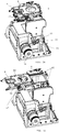
Figure 3 shows a 3D view and exploded view of an accessory holder according to the first embodiment including all details of the respective displacement mechanisms included in the accessory holder. -
Figures 4a and 4b show a detail of one of the displacement mechanisms in an accessory holder according to the embodiment offigure 3 . -
Figures 5a and 5b show the accessory holder ofFigure 3 with the accessory holding drawer placed respectively in the beam path and fully extracted out of the beam path. -
Figure 6 shows an accessory holder holding a tray that is itself holding an accessory. -
Figure 7 shows an accessory holder holding a snout that is itself holding two accessories. -
Figure 8 shows the positioning of the accessory holder equipped with a snout, with respect to a patient. -
Figures 1 and2 illustrate the basic structure of an accessory holder according to the invention. In each case, theholder 1 is attachable to thenozzle 2 of a particle beam installation. In this detailed description the nozzle is described as a Pencil Beam Scanning nozzle, even though the invention is not limited to this type of irradiation nozzle. In the context of the present description, the term nozzle refers to the last part in the sequence of parts, starting with the beam source, required to produce ascanning beam 3, directed at a target, such as apatient tumour 4. The nozzle is usually the part that comprises the dosimetry device for measuring the delivered dose. In some particle therapy configurations the nozzle comprises the scanning magnets for performing the pencil beam scanning. In other particle therapy configurations the scanning magnets for performing pencil beam scanning are installed more upstream in the beam line. For example in compact gantry systems, the scanning magnets are installed upstream of the last bending magnet and the part downstream of the last bending magnet comprising the dosimetry device can be called the nozzle. - In each of the embodiments of
figure 1 and2 , theaccessory holder 1 comprises abase portion 5 that is attached (e.g. bolted) to thenozzle 2. The base portion is preferably releasably attached to the nozzle. Nevertheless, the accessory holder of the invention can stay attached to the nozzle during a complete treatment process, and may need to be removed only in case of repairs or maintenance of the installation. According to another embodiment, the accessory holder is fully integrated in the nozzle. There is then no separate base portion as the function of this base portion (i.e. carrying the first and second displacement means) is fulfilled by the nozzle itself. In this case, the base portion is part of the overall nozzle frame. - In the embodiment of
figure 1 , a firstmovable portion 6 is mounted on thebase portion 5 and configured to be movable with respect to said base portion, in the Z-direction indicated in the drawing, i.e. closer to or away from thetarget 4. Support and/or guideelements 7 and a suitable power source (not shown) are provided for guiding and driving this movement. A secondmovable portion 8 is mounted on the firstmovable portion 6 and configured to be movable in the Y-direction, with respect to said first portion, the Y-direction being perpendicular to the Z-direction. Anaccessory 9 attached to the secondmovable portion 8 can thus be moved into and out of the beam path. Further driving means (not shown) are provided for actuating this sideways movement. The secondmovable portion 8 is provided with an interface (not shown) configured for receiving anaccessory 9 and holding the accessory during the movements along the Z and Y-axes. - The interface can be a separate interface part attached to the
movable portion 8 or it can be integrated in themovable portion 8. The interface can for example comprise a slot with a locking mechanism for inserting and removing anaccessory 9 and for locking theaccessory 9 to the secondmovable portion 8, so that during motion of the secondmovable portion 8, theaccessory 9 remains attached to the secondmovable portion 8. The interface is preferably not designed to receive one particular type of accessory, but rather it is designed to receive any type of accessory that may need to be installed, such as a range shifter or an aperture. According to an advantageous embodiment, the interface comprises a rectangular receiving area provided in the movable portion (e.g. a drawer) that is configured to move into or out of the beam path, said area being delimited by side beams, into which the accessory can be inserted by sliding the accessory into said area. Locking means such as pneumatically operated locking pins are then provided for maintaining the accessory in a fixed position with respect to the moveable portion. - Therefore, held by the interface, the
accessory 9 remains attached to the secondmovable portion 8 in any position of said first and second movable portions. In this way, the accessory can be brought closer to the target and/or into and out of the beam path without removing it from the accessory holder as such. This capability allows to perform multiple irradiation steps with and without accessories in the beam path, without interrupting the treatment. - In the embodiment of
figure 2 , the same functionalities as the embodiment offigure 1 are obtained, but the roles of the movable portions are reversed. A firstmovable portion 10 is movable in the Z-direction and provided with an interface (not shown) for receiving and holding theaccessory 9. The firstmovable portion 10 is mounted on a secondmovable portion 11 and configured to move in the Z-direction with respect to said secondmovable portion 11. The secondmovable portion 11 is itself mounted on thebase portion 5, and configured to be movable in the Y-direction, with respect to saidbase portion 5. - Both embodiments shown in
figure 1 and2 are examples of how to bring the invention into practice. All of the described displacement means are motorized and actuatable from a distance, through the use of suitable drive and actuator means, such as electrical motors, pneumatic actuators or the like. The first embodiment shown infigure 1 is the preferred option as it allows the secondmovable portion 8, i.e. the portion that is slidable sideways with respect to the beam direction, to be produced in a manner that takes up a minimum of space in said beam direction, as will be illustrated in a detailed embodiment described further on. Variations on the designs offigures 1 and2 may be obtained by specific ranges for the Z and Y movements, the angle between said Z and Y- movements, or the capability of moving the accessory in multiple directions oriented at a non-zero angle with respect to the Z-direction. The secondmoveable portions - The Z and Y directions are examples of the 'first' and 'second' direction referred to in the claims. Another way of referring to these directions may be 'longitudinal' and 'lateral' directions. The described movements in the Z-direction are examples of movements 'in the direction of a beam produced by the apparatus' referred to in the appended claims. Movements that are oriented at an angle to Z but according to which a movable portion still approaches towards or recedes away from the target, also qualify as said movements 'in the direction of a beam produced by the apparatus'.
- The advantages obtained by the accessory holder of the invention are related to the efficiency of operating the particle beam installation : irradiation with and without an accessory in the beam path can be effected with the accessory remaining attached to the holder, and without interrupting the treatment or at least without manually adjusting the accessory. At the same time, irradiations can be performed with the accessory at various positions in the direction of the beam path. For example, when shallow target volumes, i.e. target volumes close to the skin surface need to be treated, a range shifter needs to be installed in the beam line in order to further reduce the minimum energy of the particle therapy apparatus. For example if the minimum energy of the particle therapy apparatus corresponds to a depth in the patient of 5 cm, and shallow tumours close to the skin surface need to be treated, then such a range shifter needs to be used to reduce the penetration depth of the beam with a few cm. With the accessory holder according to the invention, a standard range shifter can be installed in the accessory holder and when a treatment requires the range shifting, the range shifter can be inserted when needed. With the motion of the second movable portion being automated, this insert or extraction of a range shifter can be done without manual intervention of the radiotherapist. The motion can be actuated either from a control in the treatment room or from a control outside the treatment room.
- In
figures 3 ,4 and5 , a detailed view is shown of an accessory holder for a PBS nozzle according to a specific embodiment working according to the principle offigure 1 .Figure 3 shows a 3D view of theaccessory holder 1 according to the invention, holding a circle-shapedaperture accessory 9. The blow-up view illustrates the main components. Thebase portion 5 is a box-shaped piece assembled from machined plates (e.g. steel).Support plates 20 are provided withholes 21 through which thebase portion 5 can be bolted to the face of the nozzle (not shown). Bottom andtop openings axle 24, rotatable with respect to thebase portion 5, passes throughholes 25 in two opposite side walls of the base portion. The axle is eccentrically placed in the base portion, i.e. it is located laterally with respect to the base portion's center plane perpendicular to said opposite walls, in a position so that it is unable to block the beams passing through theopenings 22/23. - The axle's rotation in the two rotation directions is driven by an
electric motor 26. Fixed to theaxle 24, i.e. rotating together with the axle, twoactuator arms 27 are mounted, one on each side of thebase portion 5. The actuator arms haveelongate openings 28, configured to receive acylindrical protrusion 29 of asupport piece 30. To each of the twosupport pieces 30, a pair ofcylindrical rods 35 is connected by inserting the rods intoopenings 37 of the support pieces and securing them by securingpins 38. Therods 35 are inserted inopenings 39 provided in the upper surface of thebase portion 5. The shape and dimensions of theelongate openings 28 and theprotrusions 29 as well as their respective materials are selected such that rotation of theaxle 24 actuates a linear movement of therods 35 guided by theholes 39, through the movement of theprotrusions 29 inside theelongate openings 28. The two extreme positions of this mechanism are shown in more detail infigures 4a and 4b . The shape of the twoactuator arms 27 is different in this embodiment, as these arms have been designed to actuate the exact same movement of therods 35, taking into account a torsional deformation of theaxle 24. - The set of four
rods 35 supports the firstmovable portion 6 which is, in this embodiment, a flat rectangular frame attached to the end of therods 35. The second movable portion is, in this embodiment, aslidable drawer 8 configured to move perpendicularly to therods 35, driven by a pneumatic drive mechanism.Figures 5a and 5b show the two extreme positions of thedrawer 8. The drawer is guided by lateral guides or rails 45 on the firstmovable portion 6. - The
drawer 8 comprises a rectangular receiving area delimited byside beams 46, into which the accessory can be inserted by sliding the accessory into said area. Pneumatically operated locking pins 47 are provided for maintaining the accessory in a fixed position with respect to thedrawer 8. So in this embodiment, the interface is not a separate piece, but it is incorporated in the drawer itself (the second movable portion referred to in the claims). The element that is inserted into the drawer can be theaperture piece 9 shown in the drawings, or it can be a support element such as a tray or a snout, that is itself designed to carry the accessory, e.g. a range shifter. The support element is then designed to fit into the drawer, in the same way that is shown for theaperture piece 9. - According to the specific embodiment shown in
Fig 3 ,4 and5 , the drawer can move along the central beam direction away from or towards the nozzle over a distance of maximum 25 cm. Preferably, the first displacement means for moving the accessory interface in a first direction allow for movement of the interface over a distance of more than 10 cm. More preferably, the first displacement means allow for movement of the interface over a distance of more than 20 cm. - Other elements that are visible in
figures 3 and5 , but are not essential to the general concept of the invention include the following: abrake 60 for stopping the movement of therods 35 andpneumatic supply lines 61. - As stated, the
accessory 9 can be an aperture, a range shifter, a ridge filter, a range compensator or any other type accessory. What is drawn as theaccessory 9 infigures 1 and2 can also be itself a means for holding other accessories such as an aperture piece, range shifter etc.Figure 6 illustrates an embodiment wherein theaccessory 9 comprises atray 55 configured for fitting in a slot of theinterface 81 as illustrated inFigure 6a and Figure 6b . On thetray 55, arange shifter 53 or another accessory, such as a ridge filter or an aperture, can be attached.Figure 6b shows thetray 55 attached to theinterface 81 of theaccessory holder 1 whereby, in this illustration, theinterface 81 of theaccessory holder 1 is in a position out of acentral beam path 3. In this example, thetray 55 fulfils the role of an accessory holding element. - In the embodiment illustrated in
Figure 7 , theaccessory 9 comprises asnout 50 attachable to theinterface 81 of the secondmovable portion 8. Thesnout 50 can for example be configured for fitting in a slot of theinterface 81. Thesnout 50 itself is a structure having a base 100 and a protrudingportion 101 provided at the end with a plurality of slots or other means into which accessories can be fitted. The snout thus allows to hold one or more accessories such as an aperture or a range compensator or a ridge filter or a range shifter. Thesnout 50 can for example comprise two slots (not shown on the figure) for receiving two accessories at the same time, for example an aperture and a range compensator.Figure 7a shows asnout 55 holding twoaccessories Figure 7b shows theaccessory holder 1 attached to anozzle 2 whereby thesnout 55 is positioned in acentral beam path 3.Figure 7c shows thesame snout 55 as inFigure 7b but in a geometry whereby the snout is positioned out of acentral beam path 3 using the secondmovable portion 8 and whereby the snout is located closer to the nozzle when compared toFigure 7b by using the motion of the firstmovable portion 6. The advantage of attaching asnout 50 to theaccessory holder 1 is that accessories (aperture, range compensator, ridge filter, range shifter) can be brought very close to the patient as illustrated inFigure 8 . For example, for a head treatment, asnout 50 with a small diameter is used so that the shoulder of thepatient 90 is not in collision with the snout. Typically, a library of different snouts having different diameters will be available for the particle therapy apparatus. For example a library of three different snouts can comprise a first snout for holding circular accessories having a diameter up to 12 cm, a second snout for holding circular accessories having a diameter up to 20 cm and a third snout for holding accessories having a rectangular shape of for example 28 cm x 38 cm. On eachsnout 50, correspondingaccessories snout 50 fulfils the role of an accessory holding element. - Other displacement mechanisms may be used instead of the ones shown in the embodiment of
figures 3 to 5 , for example a system comprising anextendable portion 6 that is movable on a set of rails, as it is known for supporting and moving a collimator closer to or away from the target in a double scattering installation. According to an embodiment however, the displacement mechanism for movement in the direction of the beam does not comprise nor consist of a bellows-type mechanism. The mechanism comprising theactuator arms 27 andsupport rods 35 has however a specific advantage in that it is very compact in the direction of the beam. Given that the accessory holder must be able to further support and manipulate the secondmovable portion 8, this provides a maximum of movement space for the accessory. - The invention therefore finds its primary use in PBS scanning installations, wherein a variety of accessories, including an aperture piece for, for example, sparing organs at risk, can be positioned with the holder of the invention.
- While the invention has been illustrated and described in detail in the drawings and foregoing description, such illustration and description are to be considered illustrative or exemplary and not restrictive. Other variations to the disclosed embodiments can be understood and effected by those skilled in the art in practicing the claimed invention, from a study of the drawings, the disclosure and the appended claims. In the claims, the word "comprising" does not exclude other elements or steps, and the indefinite article "a" or "an" does not exclude a plurality. The mere fact that certain measures are recited in mutually different dependent claims does not indicate that a combination of these measures cannot be used to advantage. Any reference signs in the claims should not be construed as limiting the scope.
- The foregoing description details certain embodiments of the invention. It will be appreciated, however, that no matter how detailed the foregoing appears in text, the invention may be practiced in many ways, and is therefore not limited to the embodiments disclosed. It should be noted that the use of particular terminology when describing certain features or aspects of the invention should not be taken to imply that the terminology is being re-defined herein to be restricted to include any specific characteristics of the features or aspects of the invention with which that terminology is associated.
Claims (17)
- An accessory holder (1) for a particle beam treatment apparatus comprising a nozzle (2) for delivering a beam to a target, said holder being connectable to or integrated in said nozzle (2), the holder comprising- An accessory interface (81) configured for releasably receiving and holding an accessory (9),- First displacement means configured to move said accessory interface in a first direction, so that the accessory, while being held by said interface, may be moved away from or towards the nozzle in the direction of a beam produced by said apparatus,- Second displacement means configured to move said accessory interface in a second direction, so that the accessory, while being held by said interface, may be moved into or out of the path of the beam produced by said apparatus.
- Accessory holder according to claim 1, wherein said first displacement means comprises a first movable portion (6) configured to move in said first direction with respect to the nozzle, and wherein the second displacement means comprises a second movable portion (8) configured to move in said second direction with respect to said first movable portion (6), and wherein the second movable portion (8) comprises said accessory interface.
- Accessory holder according to claim 1, wherein said second displacement means comprises a second movable portion (10), configured to move in said second direction with respect to the nozzle and wherein the first displacement means comprises a first movable portion (10) configured to move in said first direction with respect to said second movable portion (11), and wherein the first movable portion (10) comprises said accessory interface.
- Accessory holder according to any one of claims 1 to 3, wherein said movement in the second direction, into or out of the path of the beam, is a linear translational movement.
- Accessory holder according to claim 2, wherein the first displacement means further comprises a rotatable axle (24) provided with actuator arms (27) configured to move the first movable portion (6) along said first direction away from or towards the nozzle (2).
- Accessory holder according to claim 2 or 5, wherein the second movable portion (8) comprises a slidable drawer configured to slide back and forth in said second direction, said drawer (8) comprising said interface (81) to receive and secure an accessory (9).
- Accessory holder according to any one of claims 1 to 6, comprising a base portion (5) connectable to said nozzle (2), with said first or second displacement means being mounted on said base portion (5).
- Accessory holder according to claim 5 or 6, comprising a base portion (5) connectable to said nozzle (2), with said first or second displacement means being mounted on said base portion (5), said first displacement means further comprising support pieces (30) and support rods (35) attached at one end to said support pieces and supporting the first movable portion (6) at the other end, the base portion (5) comprising guide holes (39) into which said rods are inserted, and wherein said arms (27) are provided with elongate openings (28), configured to slidably receive cylindrical ends (29) of said support pieces (30), so that rotation of said arms (27) actuates a linear movement of said support rods (35).
- Accessory holder according to any one of the preceding claims, wherein the first and the second displacement means are motorized and actuatable from a distance.
- Accessory holder according to claim 9, wherein wherein the first and/or the second displacement means comprises electrical and/or pneumatic drive means.
- Accessory holder according to any one of the preceding claims, wherein said first direction is the direction of a first linear path, and wherein the second direction is the direction of a second linear path perpendicular to the first linear path.
- A particle beam apparatus comprising an irradiation source and a nozzle (2), with an accessory holder (1) according to any one of the preceding claims mounted on or incorporated in said nozzle (2).
- Particle beam apparatus according to claim 12, wherein said apparatus comprises a particle beam scanning device for scanning a particle beam over a target.
- Particle beam apparatus according to claim 12 or 13 further comprising a snout (50) attachable to said accessory holder (1) and whereby said snout (50) is further configured for holding one or more accessories (51,52) such as an aperture, a range compensator, a ridge filter or a range shifter.
- A method for positioning an accessory in a particle beam treatment apparatus comprising a nozzle (2) for delivering a beam to a target (4) and an accessory holder (1) connected to or integrated in said nozzle, said holder comprising :- An accessory interface (81) configured for releasably receiving and holding an accessory (9),- First displacement means configured to move said accessory interface in a first direction, so that the accessory, while being held by said interface, may be moved away from or towards the nozzle in the direction of a beam produced by said apparatus,- Second displacement means configured to move said accessory interface in a second direction, so that the accessory, while being held by said interface, may be moved into or out of the path of the beam produced by said apparatus,the method comprising the steps of :• inserting and securing the accessory (9) in said accessory interface (81),• moving the accessory along the first and second direction or vice versa, thereby bringing the accessory in a predefined position with respect to said target (4), wherein the accessory remains inserted and secured in said interface during said movements.
- Method according to claim 15, wherein said movements are actuated by automated drive means controlled by an operator.
- A method according to claim 15 or 16 wherein said accessory (9) is an aperture piece or a range shifter or a ridge filter for use with a Pencil Beam Scanning nozzle or wherein said accessory (9) is a holding means (50,55) holding such an aperture piece, range shifter or ridge filter.
Priority Applications (1)
| Application Number | Priority Date | Filing Date | Title |
|---|---|---|---|
| EP14715233.4A EP2978495B1 (en) | 2013-03-26 | 2014-03-26 | Accessory holder for particle beam apparatus |
Applications Claiming Priority (3)
| Application Number | Priority Date | Filing Date | Title |
|---|---|---|---|
| EP13161202 | 2013-03-26 | ||
| PCT/EP2014/056044 WO2014154740A1 (en) | 2013-03-26 | 2014-03-26 | Accessory holder for particle beam apparatus |
| EP14715233.4A EP2978495B1 (en) | 2013-03-26 | 2014-03-26 | Accessory holder for particle beam apparatus |
Publications (2)
| Publication Number | Publication Date |
|---|---|
| EP2978495A1 EP2978495A1 (en) | 2016-02-03 |
| EP2978495B1 true EP2978495B1 (en) | 2018-05-09 |
Family
ID=47997153
Family Applications (1)
| Application Number | Title | Priority Date | Filing Date |
|---|---|---|---|
| EP14715233.4A Active EP2978495B1 (en) | 2013-03-26 | 2014-03-26 | Accessory holder for particle beam apparatus |
Country Status (5)
| Country | Link |
|---|---|
| US (1) | US9789343B2 (en) |
| EP (1) | EP2978495B1 (en) |
| JP (1) | JP6505664B2 (en) |
| ES (1) | ES2673398T3 (en) |
| WO (1) | WO2014154740A1 (en) |
Families Citing this family (22)
| Publication number | Priority date | Publication date | Assignee | Title |
|---|---|---|---|---|
| US9737734B2 (en) * | 2008-05-22 | 2017-08-22 | Susan L. Michaud | Charged particle translation slide control apparatus and method of use thereof |
| US10751551B2 (en) | 2010-04-16 | 2020-08-25 | James P. Bennett | Integrated imaging-cancer treatment apparatus and method of use thereof |
| US10376717B2 (en) | 2010-04-16 | 2019-08-13 | James P. Bennett | Intervening object compensating automated radiation treatment plan development apparatus and method of use thereof |
| US10555710B2 (en) | 2010-04-16 | 2020-02-11 | James P. Bennett | Simultaneous multi-axes imaging apparatus and method of use thereof |
| US10589128B2 (en) | 2010-04-16 | 2020-03-17 | Susan L. Michaud | Treatment beam path verification in a cancer therapy apparatus and method of use thereof |
| US10518109B2 (en) | 2010-04-16 | 2019-12-31 | Jillian Reno | Transformable charged particle beam path cancer therapy apparatus and method of use thereof |
| US10625097B2 (en) | 2010-04-16 | 2020-04-21 | Jillian Reno | Semi-automated cancer therapy treatment apparatus and method of use thereof |
| US10179250B2 (en) | 2010-04-16 | 2019-01-15 | Nick Ruebel | Auto-updated and implemented radiation treatment plan apparatus and method of use thereof |
| US10188877B2 (en) | 2010-04-16 | 2019-01-29 | W. Davis Lee | Fiducial marker/cancer imaging and treatment apparatus and method of use thereof |
| US10556126B2 (en) | 2010-04-16 | 2020-02-11 | Mark R. Amato | Automated radiation treatment plan development apparatus and method of use thereof |
| US10349906B2 (en) | 2010-04-16 | 2019-07-16 | James P. Bennett | Multiplexed proton tomography imaging apparatus and method of use thereof |
| JP6433792B2 (en) * | 2015-01-15 | 2018-12-05 | 株式会社東芝 | Particle beam therapy apparatus and imaging method using the same |
| US9907981B2 (en) * | 2016-03-07 | 2018-03-06 | Susan L. Michaud | Charged particle translation slide control apparatus and method of use thereof |
| US10037863B2 (en) | 2016-05-27 | 2018-07-31 | Mark R. Amato | Continuous ion beam kinetic energy dissipater apparatus and method of use thereof |
| US11103730B2 (en) | 2017-02-23 | 2021-08-31 | Mevion Medical Systems, Inc. | Automated treatment in particle therapy |
| GB2576339B (en) * | 2018-08-15 | 2021-07-28 | Elekta ltd | Radiation therapy apparatus |
| JP7500159B2 (en) * | 2018-11-27 | 2024-06-17 | 東芝エネルギーシステムズ株式会社 | PARTICLE BEAM THERAPY APPARATUS AND METHOD FOR OPERATION OF PARTICLE BEAM THERAPY APPARATUS - Patent application |
| US12251576B2 (en) * | 2020-09-30 | 2025-03-18 | Varian Medical Systems, Inc. | Electromagnetic interface mount for radiation machines |
| US20220270777A1 (en) * | 2021-02-09 | 2022-08-25 | Mayo Foundation For Medical Education And Research | Dynamic Pinhole Aperture for Charged Particle Therapy Systems |
| US12245355B2 (en) | 2021-02-19 | 2025-03-04 | Mevion Medical Systems, Inc. | Gantry for a particle therapy system |
| EP4112122A1 (en) * | 2021-07-02 | 2023-01-04 | Martin Dux | Tool for adjusting linear accelerator crosslinking for radiotherapy |
| CN116981150B (en) * | 2023-08-01 | 2024-01-23 | 迈胜医疗设备有限公司 | Range shifter, control method and radiotherapy equipment |
Family Cites Families (16)
| Publication number | Priority date | Publication date | Assignee | Title |
|---|---|---|---|---|
| JPS52144671U (en) * | 1976-04-26 | 1977-11-02 | ||
| JP3532739B2 (en) * | 1997-08-07 | 2004-05-31 | 住友重機械工業株式会社 | Radiation field forming member fixing device |
| JPH11142600A (en) * | 1997-11-12 | 1999-05-28 | Mitsubishi Electric Corp | Charged particle beam irradiation apparatus and irradiation method |
| JP2001161840A (en) * | 1999-12-08 | 2001-06-19 | Hitachi Ltd | Radiotherapy equipment |
| US6777700B2 (en) * | 2002-06-12 | 2004-08-17 | Hitachi, Ltd. | Particle beam irradiation system and method of adjusting irradiation apparatus |
| JP4114590B2 (en) * | 2003-10-24 | 2008-07-09 | 株式会社日立製作所 | Particle beam therapy system |
| JP4255860B2 (en) * | 2004-02-26 | 2009-04-15 | 株式会社日立製作所 | Radiation therapy bolus manufacturing method and manufacturing apparatus |
| US7208748B2 (en) | 2004-07-21 | 2007-04-24 | Still River Systems, Inc. | Programmable particle scatterer for radiation therapy beam formation |
| US7547901B2 (en) * | 2006-06-05 | 2009-06-16 | Varian Medical Systems, Inc. | Multiple beam path particle source |
| US8003964B2 (en) * | 2007-10-11 | 2011-08-23 | Still River Systems Incorporated | Applying a particle beam to a patient |
| EP2363170B1 (en) * | 2007-11-30 | 2014-01-08 | Mevion Medical Systems, Inc. | Inner gantry |
| JP5047083B2 (en) * | 2008-07-11 | 2012-10-10 | 株式会社日立製作所 | Particle beam therapy system |
| WO2010122662A1 (en) | 2009-04-24 | 2010-10-28 | 三菱電機株式会社 | Particle radiation therapy apparatus |
| JP5225200B2 (en) | 2009-05-27 | 2013-07-03 | 三菱電機株式会社 | Particle beam therapy system |
| US8716679B2 (en) | 2009-12-28 | 2014-05-06 | National University Corporation Gunma University | Beam irradiation apparatus and beam irradiation control method |
| CN103687648B (en) | 2011-07-21 | 2016-03-30 | 三菱电机株式会社 | Particle-beam therapeutic apparatus |
-
2014
- 2014-03-26 ES ES14715233.4T patent/ES2673398T3/en active Active
- 2014-03-26 EP EP14715233.4A patent/EP2978495B1/en active Active
- 2014-03-26 WO PCT/EP2014/056044 patent/WO2014154740A1/en not_active Ceased
- 2014-03-26 US US14/779,790 patent/US9789343B2/en active Active
- 2014-03-26 JP JP2016504655A patent/JP6505664B2/en active Active
Non-Patent Citations (1)
| Title |
|---|
| None * |
Also Published As
| Publication number | Publication date |
|---|---|
| EP2978495A1 (en) | 2016-02-03 |
| ES2673398T3 (en) | 2018-06-21 |
| WO2014154740A1 (en) | 2014-10-02 |
| JP2016514521A (en) | 2016-05-23 |
| US20160045769A1 (en) | 2016-02-18 |
| US9789343B2 (en) | 2017-10-17 |
| JP6505664B2 (en) | 2019-04-24 |
Similar Documents
| Publication | Publication Date | Title |
|---|---|---|
| US9789343B2 (en) | Accessory holder for particle beam apparatus | |
| JP3655292B2 (en) | Particle beam irradiation apparatus and method for adjusting charged particle beam irradiation apparatus | |
| JP5180197B2 (en) | Multiple beam system | |
| EP3549637B1 (en) | Focusing magnet and charged particle irradiation apparatus | |
| CN105288871B (en) | A kind of particle-irradiation device and particle therapy system | |
| TWI462761B (en) | Particle beam therapy device | |
| US10857385B2 (en) | Adjustable collimator, collimation system, therapy head and radiotherapy device | |
| EP2243515A1 (en) | Charged particle beam therapy system having an X-Ray imaging device | |
| CN110140429B (en) | Compact light-weight high-performance proton treatment beam line | |
| JP2008206563A (en) | Multi-leaf collimator | |
| CN108175958A (en) | Focus head, collimator and gamma knife | |
| JP5829162B2 (en) | X-ray equipment | |
| US10532227B2 (en) | Particle beam treatment system | |
| CN204522032U (en) | Straight line swing arm robot therapeutic bed | |
| JP6104839B2 (en) | Radiation therapy equipment | |
| JP2016129639A (en) | Particle beam irradiation device, particle beam treatment device, and imaging method using the same | |
| JP5419483B2 (en) | Rotating irradiation type particle beam medical device | |
| JP5551107B2 (en) | Charged particle beam irradiation equipment | |
| TWI572391B (en) | Treatment planning apparatus and particle beam therapy apparatus | |
| CN119548768A (en) | Multi-chamber particle therapy room, radiotherapy system and particle accelerator moving method | |
| KR101739648B1 (en) | Multi-leaf collimator | |
| JP3681382B2 (en) | Particle beam irradiation apparatus and method for adjusting charged particle beam irradiation apparatus | |
| CN112118890B (en) | Apparatus and methods for directing energy from multi-element sources | |
| CN215900759U (en) | Pre-collimator, treatment head and radiotherapy equipment | |
| TWI885964B (en) | Adjustment device and loading system for radiation therapy |
Legal Events
| Date | Code | Title | Description |
|---|---|---|---|
| PUAI | Public reference made under article 153(3) epc to a published international application that has entered the european phase |
Free format text: ORIGINAL CODE: 0009012 |
|
| 17P | Request for examination filed |
Effective date: 20150924 |
|
| AK | Designated contracting states |
Kind code of ref document: A1 Designated state(s): AL AT BE BG CH CY CZ DE DK EE ES FI FR GB GR HR HU IE IS IT LI LT LU LV MC MK MT NL NO PL PT RO RS SE SI SK SM TR |
|
| AX | Request for extension of the european patent |
Extension state: BA ME |
|
| DAX | Request for extension of the european patent (deleted) | ||
| 17Q | First examination report despatched |
Effective date: 20160930 |
|
| STAA | Information on the status of an ep patent application or granted ep patent |
Free format text: STATUS: EXAMINATION IS IN PROGRESS |
|
| GRAP | Despatch of communication of intention to grant a patent |
Free format text: ORIGINAL CODE: EPIDOSNIGR1 |
|
| STAA | Information on the status of an ep patent application or granted ep patent |
Free format text: STATUS: GRANT OF PATENT IS INTENDED |
|
| INTG | Intention to grant announced |
Effective date: 20170531 |
|
| RAP1 | Party data changed (applicant data changed or rights of an application transferred) |
Owner name: ION BEAM APPLICATIONS S.A. |
|
| RIN1 | Information on inventor provided before grant (corrected) |
Inventor name: AMELIA, JEAN-CLAUDE Inventor name: COLMANT, THOMAS Inventor name: DE ROECK, SVEN |
|
| GRAJ | Information related to disapproval of communication of intention to grant by the applicant or resumption of examination proceedings by the epo deleted |
Free format text: ORIGINAL CODE: EPIDOSDIGR1 |
|
| STAA | Information on the status of an ep patent application or granted ep patent |
Free format text: STATUS: EXAMINATION IS IN PROGRESS |
|
| GRAP | Despatch of communication of intention to grant a patent |
Free format text: ORIGINAL CODE: EPIDOSNIGR1 |
|
| STAA | Information on the status of an ep patent application or granted ep patent |
Free format text: STATUS: GRANT OF PATENT IS INTENDED |
|
| INTC | Intention to grant announced (deleted) | ||
| INTG | Intention to grant announced |
Effective date: 20171108 |
|
| GRAS | Grant fee paid |
Free format text: ORIGINAL CODE: EPIDOSNIGR3 |
|
| GRAA | (expected) grant |
Free format text: ORIGINAL CODE: 0009210 |
|
| STAA | Information on the status of an ep patent application or granted ep patent |
Free format text: STATUS: THE PATENT HAS BEEN GRANTED |
|
| AK | Designated contracting states |
Kind code of ref document: B1 Designated state(s): AL AT BE BG CH CY CZ DE DK EE ES FI FR GB GR HR HU IE IS IT LI LT LU LV MC MK MT NL NO PL PT RO RS SE SI SK SM TR |
|
| REG | Reference to a national code |
Ref country code: GB Ref legal event code: FG4D |
|
| REG | Reference to a national code |
Ref country code: CH Ref legal event code: EP Ref country code: AT Ref legal event code: REF Ref document number: 997027 Country of ref document: AT Kind code of ref document: T Effective date: 20180515 |
|
| REG | Reference to a national code |
Ref country code: IE Ref legal event code: FG4D |
|
| REG | Reference to a national code |
Ref country code: DE Ref legal event code: R096 Ref document number: 602014025184 Country of ref document: DE |
|
| REG | Reference to a national code |
Ref country code: ES Ref legal event code: FG2A Ref document number: 2673398 Country of ref document: ES Kind code of ref document: T3 Effective date: 20180621 |
|
| RAP2 | Party data changed (patent owner data changed or rights of a patent transferred) |
Owner name: ION BEAM APPLICATIONS S.A. |
|
| REG | Reference to a national code |
Ref country code: NO Ref legal event code: T2 Effective date: 20180509 |
|
| REG | Reference to a national code |
Ref country code: NL Ref legal event code: MP Effective date: 20180509 |
|
| REG | Reference to a national code |
Ref country code: LT Ref legal event code: MG4D |
|
| PG25 | Lapsed in a contracting state [announced via postgrant information from national office to epo] |
Ref country code: FI Free format text: LAPSE BECAUSE OF FAILURE TO SUBMIT A TRANSLATION OF THE DESCRIPTION OR TO PAY THE FEE WITHIN THE PRESCRIBED TIME-LIMIT Effective date: 20180509 Ref country code: LT Free format text: LAPSE BECAUSE OF FAILURE TO SUBMIT A TRANSLATION OF THE DESCRIPTION OR TO PAY THE FEE WITHIN THE PRESCRIBED TIME-LIMIT Effective date: 20180509 Ref country code: BG Free format text: LAPSE BECAUSE OF FAILURE TO SUBMIT A TRANSLATION OF THE DESCRIPTION OR TO PAY THE FEE WITHIN THE PRESCRIBED TIME-LIMIT Effective date: 20180809 Ref country code: SE Free format text: LAPSE BECAUSE OF FAILURE TO SUBMIT A TRANSLATION OF THE DESCRIPTION OR TO PAY THE FEE WITHIN THE PRESCRIBED TIME-LIMIT Effective date: 20180509 |
|
| PG25 | Lapsed in a contracting state [announced via postgrant information from national office to epo] |
Ref country code: RS Free format text: LAPSE BECAUSE OF FAILURE TO SUBMIT A TRANSLATION OF THE DESCRIPTION OR TO PAY THE FEE WITHIN THE PRESCRIBED TIME-LIMIT Effective date: 20180509 Ref country code: HR Free format text: LAPSE BECAUSE OF FAILURE TO SUBMIT A TRANSLATION OF THE DESCRIPTION OR TO PAY THE FEE WITHIN THE PRESCRIBED TIME-LIMIT Effective date: 20180509 Ref country code: LV Free format text: LAPSE BECAUSE OF FAILURE TO SUBMIT A TRANSLATION OF THE DESCRIPTION OR TO PAY THE FEE WITHIN THE PRESCRIBED TIME-LIMIT Effective date: 20180509 Ref country code: GR Free format text: LAPSE BECAUSE OF FAILURE TO SUBMIT A TRANSLATION OF THE DESCRIPTION OR TO PAY THE FEE WITHIN THE PRESCRIBED TIME-LIMIT Effective date: 20180810 Ref country code: NL Free format text: LAPSE BECAUSE OF FAILURE TO SUBMIT A TRANSLATION OF THE DESCRIPTION OR TO PAY THE FEE WITHIN THE PRESCRIBED TIME-LIMIT Effective date: 20180509 |
|
| REG | Reference to a national code |
Ref country code: AT Ref legal event code: MK05 Ref document number: 997027 Country of ref document: AT Kind code of ref document: T Effective date: 20180509 |
|
| PG25 | Lapsed in a contracting state [announced via postgrant information from national office to epo] |
Ref country code: SK Free format text: LAPSE BECAUSE OF FAILURE TO SUBMIT A TRANSLATION OF THE DESCRIPTION OR TO PAY THE FEE WITHIN THE PRESCRIBED TIME-LIMIT Effective date: 20180509 Ref country code: CZ Free format text: LAPSE BECAUSE OF FAILURE TO SUBMIT A TRANSLATION OF THE DESCRIPTION OR TO PAY THE FEE WITHIN THE PRESCRIBED TIME-LIMIT Effective date: 20180509 Ref country code: RO Free format text: LAPSE BECAUSE OF FAILURE TO SUBMIT A TRANSLATION OF THE DESCRIPTION OR TO PAY THE FEE WITHIN THE PRESCRIBED TIME-LIMIT Effective date: 20180509 Ref country code: PL Free format text: LAPSE BECAUSE OF FAILURE TO SUBMIT A TRANSLATION OF THE DESCRIPTION OR TO PAY THE FEE WITHIN THE PRESCRIBED TIME-LIMIT Effective date: 20180509 Ref country code: DK Free format text: LAPSE BECAUSE OF FAILURE TO SUBMIT A TRANSLATION OF THE DESCRIPTION OR TO PAY THE FEE WITHIN THE PRESCRIBED TIME-LIMIT Effective date: 20180509 Ref country code: AT Free format text: LAPSE BECAUSE OF FAILURE TO SUBMIT A TRANSLATION OF THE DESCRIPTION OR TO PAY THE FEE WITHIN THE PRESCRIBED TIME-LIMIT Effective date: 20180509 Ref country code: EE Free format text: LAPSE BECAUSE OF FAILURE TO SUBMIT A TRANSLATION OF THE DESCRIPTION OR TO PAY THE FEE WITHIN THE PRESCRIBED TIME-LIMIT Effective date: 20180509 |
|
| REG | Reference to a national code |
Ref country code: DE Ref legal event code: R097 Ref document number: 602014025184 Country of ref document: DE |
|
| PG25 | Lapsed in a contracting state [announced via postgrant information from national office to epo] |
Ref country code: IT Free format text: LAPSE BECAUSE OF FAILURE TO SUBMIT A TRANSLATION OF THE DESCRIPTION OR TO PAY THE FEE WITHIN THE PRESCRIBED TIME-LIMIT Effective date: 20180509 Ref country code: SM Free format text: LAPSE BECAUSE OF FAILURE TO SUBMIT A TRANSLATION OF THE DESCRIPTION OR TO PAY THE FEE WITHIN THE PRESCRIBED TIME-LIMIT Effective date: 20180509 |
|
| PLBE | No opposition filed within time limit |
Free format text: ORIGINAL CODE: 0009261 |
|
| STAA | Information on the status of an ep patent application or granted ep patent |
Free format text: STATUS: NO OPPOSITION FILED WITHIN TIME LIMIT |
|
| 26N | No opposition filed |
Effective date: 20190212 |
|
| PG25 | Lapsed in a contracting state [announced via postgrant information from national office to epo] |
Ref country code: SI Free format text: LAPSE BECAUSE OF FAILURE TO SUBMIT A TRANSLATION OF THE DESCRIPTION OR TO PAY THE FEE WITHIN THE PRESCRIBED TIME-LIMIT Effective date: 20180509 |
|
| PG25 | Lapsed in a contracting state [announced via postgrant information from national office to epo] |
Ref country code: MC Free format text: LAPSE BECAUSE OF FAILURE TO SUBMIT A TRANSLATION OF THE DESCRIPTION OR TO PAY THE FEE WITHIN THE PRESCRIBED TIME-LIMIT Effective date: 20180509 |
|
| REG | Reference to a national code |
Ref country code: CH Ref legal event code: PL |
|
| GBPC | Gb: european patent ceased through non-payment of renewal fee |
Effective date: 20190326 |
|
| PG25 | Lapsed in a contracting state [announced via postgrant information from national office to epo] |
Ref country code: LU Free format text: LAPSE BECAUSE OF NON-PAYMENT OF DUE FEES Effective date: 20190326 Ref country code: AL Free format text: LAPSE BECAUSE OF FAILURE TO SUBMIT A TRANSLATION OF THE DESCRIPTION OR TO PAY THE FEE WITHIN THE PRESCRIBED TIME-LIMIT Effective date: 20180509 |
|
| PG25 | Lapsed in a contracting state [announced via postgrant information from national office to epo] |
Ref country code: GB Free format text: LAPSE BECAUSE OF NON-PAYMENT OF DUE FEES Effective date: 20190326 Ref country code: LI Free format text: LAPSE BECAUSE OF NON-PAYMENT OF DUE FEES Effective date: 20190331 Ref country code: CH Free format text: LAPSE BECAUSE OF NON-PAYMENT OF DUE FEES Effective date: 20190331 Ref country code: IE Free format text: LAPSE BECAUSE OF NON-PAYMENT OF DUE FEES Effective date: 20190326 |
|
| PG25 | Lapsed in a contracting state [announced via postgrant information from national office to epo] |
Ref country code: TR Free format text: LAPSE BECAUSE OF FAILURE TO SUBMIT A TRANSLATION OF THE DESCRIPTION OR TO PAY THE FEE WITHIN THE PRESCRIBED TIME-LIMIT Effective date: 20180509 |
|
| PG25 | Lapsed in a contracting state [announced via postgrant information from national office to epo] |
Ref country code: PT Free format text: LAPSE BECAUSE OF FAILURE TO SUBMIT A TRANSLATION OF THE DESCRIPTION OR TO PAY THE FEE WITHIN THE PRESCRIBED TIME-LIMIT Effective date: 20180910 Ref country code: MT Free format text: LAPSE BECAUSE OF NON-PAYMENT OF DUE FEES Effective date: 20190326 |
|
| PG25 | Lapsed in a contracting state [announced via postgrant information from national office to epo] |
Ref country code: CY Free format text: LAPSE BECAUSE OF FAILURE TO SUBMIT A TRANSLATION OF THE DESCRIPTION OR TO PAY THE FEE WITHIN THE PRESCRIBED TIME-LIMIT Effective date: 20180509 |
|
| PG25 | Lapsed in a contracting state [announced via postgrant information from national office to epo] |
Ref country code: IS Free format text: LAPSE BECAUSE OF FAILURE TO SUBMIT A TRANSLATION OF THE DESCRIPTION OR TO PAY THE FEE WITHIN THE PRESCRIBED TIME-LIMIT Effective date: 20180909 |
|
| PG25 | Lapsed in a contracting state [announced via postgrant information from national office to epo] |
Ref country code: HU Free format text: LAPSE BECAUSE OF FAILURE TO SUBMIT A TRANSLATION OF THE DESCRIPTION OR TO PAY THE FEE WITHIN THE PRESCRIBED TIME-LIMIT; INVALID AB INITIO Effective date: 20140326 |
|
| PG25 | Lapsed in a contracting state [announced via postgrant information from national office to epo] |
Ref country code: MK Free format text: LAPSE BECAUSE OF FAILURE TO SUBMIT A TRANSLATION OF THE DESCRIPTION OR TO PAY THE FEE WITHIN THE PRESCRIBED TIME-LIMIT Effective date: 20180509 |
|
| P01 | Opt-out of the competence of the unified patent court (upc) registered |
Effective date: 20230517 |
|
| PGFP | Annual fee paid to national office [announced via postgrant information from national office to epo] |
Ref country code: ES Payment date: 20250401 Year of fee payment: 12 |
|
| PGFP | Annual fee paid to national office [announced via postgrant information from national office to epo] |
Ref country code: NO Payment date: 20260327 Year of fee payment: 13 Ref country code: DE Payment date: 20260327 Year of fee payment: 13 |
|
| PGFP | Annual fee paid to national office [announced via postgrant information from national office to epo] |
Ref country code: BE Payment date: 20260327 Year of fee payment: 13 |
|
| PGFP | Annual fee paid to national office [announced via postgrant information from national office to epo] |
Ref country code: FR Payment date: 20260325 Year of fee payment: 13 |