EP2977976A2 - Context-aware landing zone classification - Google Patents
Context-aware landing zone classification Download PDFInfo
- Publication number
- EP2977976A2 EP2977976A2 EP15177475.9A EP15177475A EP2977976A2 EP 2977976 A2 EP2977976 A2 EP 2977976A2 EP 15177475 A EP15177475 A EP 15177475A EP 2977976 A2 EP2977976 A2 EP 2977976A2
- Authority
- EP
- European Patent Office
- Prior art keywords
- context
- landing zone
- landing
- data
- potential
- Prior art date
- Legal status (The legal status is an assumption and is not a legal conclusion. Google has not performed a legal analysis and makes no representation as to the accuracy of the status listed.)
- Ceased
Links
Images

Classifications
-
- G—PHYSICS
- G08—SIGNALLING
- G08G—TRAFFIC CONTROL SYSTEMS
- G08G5/00—Traffic control systems for aircraft
- G08G5/50—Navigation or guidance aids
- G08G5/55—Navigation or guidance aids for a single aircraft
-
- B—PERFORMING OPERATIONS; TRANSPORTING
- B64—AIRCRAFT; AVIATION; COSMONAUTICS
- B64U—UNMANNED AERIAL VEHICLES [UAV]; EQUIPMENT THEREFOR
- B64U10/00—Type of UAV
- B64U10/10—Rotorcrafts
- B64U10/17—Helicopters
-
- G—PHYSICS
- G01—MEASURING; TESTING
- G01C—MEASURING DISTANCES, LEVELS OR BEARINGS; SURVEYING; NAVIGATION; GYROSCOPIC INSTRUMENTS; PHOTOGRAMMETRY OR VIDEOGRAMMETRY
- G01C21/00—Navigation; Navigational instruments not provided for in groups G01C1/00 - G01C19/00
- G01C21/20—Instruments for performing navigational calculations
-
- G—PHYSICS
- G08—SIGNALLING
- G08G—TRAFFIC CONTROL SYSTEMS
- G08G5/00—Traffic control systems for aircraft
- G08G5/20—Arrangements for acquiring, generating, sharing or displaying traffic information
- G08G5/21—Arrangements for acquiring, generating, sharing or displaying traffic information located onboard the aircraft
-
- G—PHYSICS
- G08—SIGNALLING
- G08G—TRAFFIC CONTROL SYSTEMS
- G08G5/00—Traffic control systems for aircraft
- G08G5/50—Navigation or guidance aids
- G08G5/54—Navigation or guidance aids for approach or landing
-
- G—PHYSICS
- G08—SIGNALLING
- G08G—TRAFFIC CONTROL SYSTEMS
- G08G5/00—Traffic control systems for aircraft
- G08G5/50—Navigation or guidance aids
- G08G5/57—Navigation or guidance aids for unmanned aircraft
-
- G—PHYSICS
- G08—SIGNALLING
- G08G—TRAFFIC CONTROL SYSTEMS
- G08G5/00—Traffic control systems for aircraft
- G08G5/70—Arrangements for monitoring traffic-related situations or conditions
- G08G5/74—Arrangements for monitoring traffic-related situations or conditions for monitoring terrain
-
- B—PERFORMING OPERATIONS; TRANSPORTING
- B64—AIRCRAFT; AVIATION; COSMONAUTICS
- B64U—UNMANNED AERIAL VEHICLES [UAV]; EQUIPMENT THEREFOR
- B64U2101/00—UAVs specially adapted for particular uses or applications
- B64U2101/30—UAVs specially adapted for particular uses or applications for imaging, photography or videography
- B64U2101/32—UAVs specially adapted for particular uses or applications for imaging, photography or videography for cartography or topography
-
- B—PERFORMING OPERATIONS; TRANSPORTING
- B64—AIRCRAFT; AVIATION; COSMONAUTICS
- B64U—UNMANNED AERIAL VEHICLES [UAV]; EQUIPMENT THEREFOR
- B64U2201/00—UAVs characterised by their flight controls
- B64U2201/10—UAVs characterised by their flight controls autonomous, i.e. by navigating independently from ground or air stations, e.g. by using inertial navigation systems [INS]
Definitions
- the subject matter disclosed herein generally relates to aircraft landing zone classification, and more particularly to context-aware landing zone classification for an aircraft.
- Optionally-piloted vehicles and unmanned aerial vehicles (UAVs) can operate without a human pilot using autonomous controls.
- OPVs and UAVs become more prevalent, they are being operated in less restricted and controlled areas.
- OPVs and UAVs are operated autonomously in flight, they must identify a landing zone prior to landing.
- OPVs and UAVs typically use an image-based system to identify geometric factors that may impede a safe landing.
- LIDAR LIght Detection and Ranging scanners
- LADAR LAser Detection and Ranging scanners
- RADAR RAdio Detection And Ranging
- images can be valuable in identifying a safe landing zone
- geometric factors may not provide enough information to determine whether a seemingly flat surface is a suitable landing site. For example, it may be difficult for image-based systems to discriminate between a dry field, a surface of a body of water, or a building top from only image information.
- a method of performing context-aware landing zone classification for an aircraft includes accessing a landing zone map, by a context-aware landing zone classification system of the aircraft, to identify potential landing zones.
- a database on the aircraft includes land cover map data and impervious surface map data. The database is queried to extract context data.
- the context data include land cover characteristics and impervious surface characteristics associated with locations corresponding to the landing zone map.
- the context-aware landing zone classification system of the aircraft evaluates the potential landing zones in view of the context data to adjust classifications of the potential landing zones and produce a context-aware landing zone classification of the potential landing zones.
- the context-aware landing zone classification of the potential landing zones is provided to landing zone selection logic of the aircraft to select a final landing zone.
- further embodiments could include receiving perception sensor data indicative of terrain representing the potential landing zones, and populating the landing zone map based on the perception sensor data.
- further embodiments could include identifying features in the perception sensor data and establishing initial classifications of the potential landing zones based on the features identified.
- land cover map data include land topology characterizations defined over multiple geographic areas.
- impervious surface map data define locations of man-made surfaces over multiple geographic areas.
- evaluating the potential landing zones further includes eliminating one or more of the potential landing zones from consideration based on the context data.
- evaluating the potential landing zones further includes applying the context data as a mask onto the landing zone map and incorporating the mask into a heuristic calculation to determine classification confidence.
- further embodiments could include receiving position data for the aircraft, determining geographic locations of the potential landing zones based on the position data, and querying the database to extract the context data based on the geographic locations of the potential landing zones.
- further embodiments could include where the aircraft is autonomously controlled during landing based on the final landing zone selected by the landing zone selection logic in response to the context-aware landing zone classification.
- a system for context-aware landing zone classification for an aircraft includes a processor and memory having instructions stored thereon that, when executed by the processor, cause the system to access a landing zone map to identify potential landing zones and query a database on the aircraft that includes land cover map data and impervious surface map data to extract context data.
- the context data include land cover characteristics and impervious surface characteristics associated with locations corresponding to the landing zone map.
- the potential landing zones are evaluated in view of the context data to adjust classifications of the potential landing zones and produce a context-aware landing zone classification of the potential landing zones.
- the context-aware landing zone classification of the potential landing zones is provided to landing zone selection logic of the aircraft to select a final landing zone.
- context-aware landing zone classification is provided for an aircraft.
- the context-aware landing zone classification can operate in conjunction with other landing zone classification systems, such as sensor-based classification, to increase the probability of selecting a safe landing zone based on fusion of land cover map data and impervious surface map data to better determine potential landing zone context.
- Other landing zone classification systems such as sensor-based classification
- contextual factors that can be determined from fused data sources include natural terrain quality such as water, forest, swamp, etc., as well as man-made impervious surfaces such as rooftops and other such factors that could impede a safe landing on what appears to be otherwise unobstructed terrain.
- Context-aware classification reduces the risk of potentially landing in a location that was determined suitable (i.e., substantially flat and smooth) based on observed features, but in reality would be a less desired and potentially unsafe landing surface.
- Embodiments do not rely upon context information from maps alone; rather, map-based context data are used to augment a landing zone map that may be based on geometric information captured from other sensors and/or databases, such as LIDAR, LADAR, RADAR, cameras, a priori digital terrain elevation data (DTED), and other such systems and data sources known in the art.
- Context-aware landing zone classification may be implemented in autonomous aircraft, such as optionally-piloted vehicles (OPVs) and unmanned aerial vehicles (UAVs), and/or may be provided to assist in human-piloted aircraft landing zone selection.
- OOVs optionally-piloted vehicles
- UAVs unmanned aerial vehicles
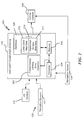
- FIG. 1 illustrates a perspective view of an exemplary vehicle in the form of an autonomous rotary-wing unmanned aerial vehicle (UAV) 100 (also referred to as “autonomous UAV 100" or “aircraft 100”) for implementing context-aware landing zone classification according to an embodiment of the invention.
- the autonomous UAV 100 is an aircraft that includes a main rotor system 102, an anti-torque system, for example, a tail rotor system 104, and a context-aware landing zone classification system 106.
- the main rotor system 102 is attached to an airframe 108 and includes a rotor hub 110 having a plurality of blades 112 that rotate about axis A.
- the tail rotor system 104 is attached aft of the main rotor system 102 and includes a plurality of blades 114 that rotate about axis B (which is orthogonal to axis A).
- the main rotor system 102 and the tail rotor system 104 are driven to rotate about their respective axes A, B by one or more turbine engines 116 through gearboxes (not shown).
- an autonomous UAV 100 is illustrated as a rotary wing UAV and described in the disclosed embodiments, it will be appreciated that other configurations and/or machines include autonomous, semi-autonomous, and human-controlled vehicles that may operate in land or water including fixed-wing aircraft, rotary-wing aircraft, marine vessels (e.g., submarines, ships, etc.), and land vehicles (e.g., trucks, cars, etc.) may also benefit from embodiments disclosed.
- autonomous, semi-autonomous, and human-controlled vehicles that may operate in land or water including fixed-wing aircraft, rotary-wing aircraft, marine vessels (e.g., submarines, ships, etc.), and land vehicles (e.g., trucks, cars, etc.) may also benefit from embodiments disclosed.
- the context-aware landing zone classification system 106 includes an aircraft computer system 118 having one or more processors and memory to process sensor data acquired from a sensing system 120.
- the sensing system 120 may be attached to or incorporated within the airframe 108.
- the sensing system 120 includes one or more perception sensors 122.
- the aircraft computer system 118 processes, in one non-limiting embodiment, raw data acquired through the sensing system 120 while the autonomous UAV 100 is airborne.
- a perception sensor processing system 124 interfaces with the perception sensors 122.
- the perception sensor processing system 124 may be incorporated within the aircraft computer system 118 or implemented as one or more separate processing systems that are in communication with the aircraft computer system 118 as part of the context-aware landing zone classification system 106.
- the aircraft computer system 118 also has a database 126 that stores context data, such as land cover map data and impervious surface map data.
- the perception sensors 122 can capture perception sensor data of a terrain 130 for processing by the aircraft computer system 118 while the autonomous UAV 100 is airborne.
- the perception sensors 122 may include one or more of: a downward-scanning LIDAR scanner, a video camera, a multi-spectral camera, a stereo camera system, a structure light-based 3D/depth sensor, a time-of-flight camera, a LADAR scanner, a RADAR scanner, or the like in order to capture perception sensor data indicative of the terrain 130 and determine geometric information and features of one or more potential landing zones 132A, 132B, and 132C for the autonomous UAV 100.
- the autonomous UAV 100 may include a navigation system 134, such as, for example, an inertial measurement unit (IMU) that may be used to acquire positional data related to a current rotation and acceleration of the autonomous UAV 100 in order to determine a geographic location of autonomous UAV 100, including a change in position of the autonomous UAV 100.
- the navigation system 134 can also or alternatively include a global positioning system (GPS) or the like to enhance positional awareness of the autonomous UAV 100.
- GPS global positioning system
- the aircraft computer system 118 of the context-aware landing zone classification system 106 performs an analysis of one or more potential landing zones 132A, 132B, and 132C based on geometric features and further refines landing zone classification based on context data.
- terrain 130 that is observed by the context-aware landing zone classification system 106 may include man-made surfaces 136 (e.g., building rooftops, roadways, bridges, etc.), such as those depicted near potential landing zone 132C that may rule out potential landing zone 132C as a final landing zone.
- potential landing zones 132A and 132B may both appear to be substantially flat surfaces, geometric feature analysis alone may be unable to accurately discern that potential landing zone 132A is located upon a water body 138.
- potential landing zone 132A can be identified as water and therefore an unsuitable landing zone. Landing zone classification and identification can perform a number of comparisons to determine suitability of any number of potential landing zones as further described herein.
- FIG. 2 illustrates a schematic block diagram of a system 200 for context-aware landing zone classification onboard the autonomous UAV 100 of FIG. 1 according to an exemplary embodiment.
- the system 200 is an embodiment of the context-aware landing zone classification system 106 of FIG. 1 .
- the system 200 includes the aircraft computer system 118 that executes instructions for implementing a context-aware landing zone classifier 202.
- the aircraft computer system 118 can receive raw sensor data on potential landing zones from one or more perception sensors 122.
- the aircraft computer system 118 includes a memory 206 that communicates with a processor 204.
- the memory 206 may store the context-aware landing zone classifier 202 as executable instructions that are executed by processor 204.
- the memory 206 is an example of a non-transitory computer readable storage medium tangibly embodied in the aircraft computer system 118 including executable instructions stored therein, for instance, as firmware. Also, in embodiments, memory 206 may include random access memory (RAM), read-only memory (ROM), or other electronic, optical, magnetic or any other computer readable medium onto which instructions and data are stored.
- the processor 204 may be any type of processor, including a general purpose processor, a digital signal processor, a microcontroller, an application specific integrated circuit, a field programmable gate array, or the like. Although depicted as singular blocks, the processor 204 and memory 206 can be distributed between multiple processing circuits and memory subsystems. In an embodiment, the processor 204 performs functions of the perception sensor processing system 124 of FIG. 1 .
- the system 200 includes the database 126.
- the database 126 may be used to store land cover map data 212, impervious surface map data 214, and other data such as potential landing zone profiles, position data from navigation system 134, geometric profiles, and the like. Data in the database 126 can be periodically updated during on-ground maintenance or updated during flight, for instance, by wireless communication or otherwise acquired by the aircraft computer system 118.
- the land cover map data 212 and the impervious surface map data 214 can be uploaded from various sources, such as U.S. Geological Survey (USGS) data, self-collected data, or other third-party sources.
- the data stored in the database 126 can be formatted for implementing the context-aware landing zone classifier 202 and can include position reference information.
- the land cover map data 212 and the impervious surface map data 214 can be formatted as two or more separate maps that are selectively fused on-demand as context data 216 based on one or more position references.
- the land cover map data 212 and the impervious surface map data 214 can be pre-fused into a two-dimensional grid of cells corresponding to locations, where each cell can include land cover characteristics and impervious surface characteristics as context data 216.
- the database 126 may be used to temporarily or permanently store data, to provide threshold and analysis criteria, to provide a record or log of the data stored therein, etc.
- the database 126 may store relationships between data, such as one or more links between data or sets of data acquired through the modalities onboard the autonomous UAV 100 of FIG. 1 to support data fusion with the land cover map data 212 and impervious surface map data 214.
- the system 200 may provide one or more controls, such as vehicle controls 208.
- the vehicle controls 208 may provide directives based on, e.g., data associated with the navigation system 134. Directives provided by the vehicle controls 208 may include navigating or repositioning the autonomous UAV 100 of FIG. 1 to an alternate landing zone for evaluation as a suitable landing zone.
- the directives may be presented on one or more input/output (I/O) devices 210.
- the I/O devices 210 may include a display device or screen, audio speakers, a graphical user interface (GUI), etc.
- GUI graphical user interface
- the I/O devices 210 may be used to enter or adjust data and linking between data or sets of data. It is to be appreciated that the system 200 is illustrative.
- additional components or entities not shown in FIG. 2 may be included.
- one or more of the components or entities may be optional.
- the components or entities of the system 200 may be arranged or configured differently from what is shown in FIG. 2 .
- the I/O device(s) 210 may be commanded by vehicle controls 208, as opposed to being commanded by the processor 204.
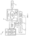
- FIG. 3 illustrates an exemplary data flow diagram 300 that is performed by the processor 204 of FIG. 2 for implementing the context-aware landing zone classifier 202 of FIG. 2 as part of the context-aware landing zone classification system 106 of FIG. 1 according to an embodiment.
- Context-based map data extraction 302 can access the land cover map data 212 and impervious surface map data 214 to extract context data 216.
- the land cover map data 212 and impervious surface map data 214 can reside in separate data structures or be stored in a single fused data structure.
- the context data 216 can include land cover characteristics and impervious surface characteristics associated with locations corresponding to a landing zone map 308.
- the land cover map data 212 may include land topology characterizations defined over multiple geographic areas, for instance, as a terrain type defined on a two-dimensional grid to distinguish open fields, wetlands, swamp, water bodies, sand, forest, and the like.
- the impervious surface map data 214 may define locations of man-made surfaces over multiple geographic areas, for example, as rooftops, concrete surfaces, asphalt surfaces, and the like.
- the impervious surface map data 214 may also be defined using a two-dimensional grid as a share grid with the land cover map data 212 or as one or more separate grids.
- Context-based landing zone classification processing 306 can include landing zone classification and identification 310 that interfaces with the context-based map data extraction 302 and the landing zone map 308 to provide context-aware landing zone classification 311 of the potential landing zones 132A-132C ( FIG. 1 ) to landing zone selection logic 312 to select a final landing zone.
- the landing zone classification and identification 310 can access the landing zone map 308 to identify the potential landing zones 132A-132C ( FIG. 1 ).
- Perception sensor data indicative of terrain 130 ( FIG. 1 ) representing potential landing zones 132A-132C ( FIG. 1 ) for the autonomous UAV 100 of FIG. 1 can be received at sensor data processing 316 from the perception sensors 122.
- the sensor data processing 316 may also receive position data 304, for example, from the navigation system 134 of FIGS. 1 and 2 .
- Sensor-based landing zone classification 318 identifies features of the potential landing zones 132A-132C of FIG. 1 in the perception sensor data as sensor-based landing zone classification data.
- the sensor-based landing zone classification 318 is an example of processing performed by the perception sensor processing system 124 of FIG. 1 .
- Reference images stored in database 126 FIGS.
- the landing zone map 308 can be populated based on the perception sensor data.
- the sensor-based landing zone classification 318 can establish initial classifications of the potential landing zones 132A-132C of FIG. 1 based on the features identified in the perception sensor data.
- the landing zone classification and identification 310 can query the database 126 via the context-based map data extraction 302 to extract context data 216 associated with locations corresponding to the landing zone map 308.
- the landing zone classification and identification 310 can evaluate the potential landing zones 132A-132C ( FIG. 1 ) in view of the context data 216 to adjust classifications of the potential landing zones 132A-132C ( FIG. 1 ) and produce a context-aware landing zone classification 311 of the potential landing zones 132A-132C ( FIG. 1 ).
- Evaluating the potential landing zones 132A-132C ( FIG. 1 ) can further include eliminating one or more of the potential landing zones 132A-132C ( FIG. 1 ) from consideration based on the context data 216 in a deterministic classification process. For example, flat and smooth surfaces of potential landing zones 132A and 132C of FIG. 1 can be eliminated from consideration upon determining that potential landing zone 132A is a water body and that potential landing zone 132C is a rooftop of a building.
- evaluating the potential landing zones 132A-132C can include applying the context data 216 as a mask onto the landing zone map 308 and incorporating the mask into a heuristic calculation to determine classification confidence in a classification weighting process.
- Classification weighting can apply confidence values to classifications in the landing zone map 308 to indicate a likelihood of a suitable/unsuitable landing zone as well as a relative confidence in the determination. As more data values are analyzed, a greater degree of confidence can be assigned to each suitable/unsuitable assessment.
- a surface that is smooth, flat, dry, and not impervious to water would more likely have a higher suitability score than a surface that is smooth and flat but wet (e.g., water body, swamp, wetlands) or characterized as a rooftop.
- various weightings and preferences can be defined in the database 126 to prefer certain landing zone attributes over others.
- Position data 304 for the autonomous UAV 100 of FIG. 1 can be received at the landing zone classification and identification 310. Geographic locations of the potential landing zones 132A-132C ( FIG. 1 ) can be determined based on the position data 304. Querying the database 126 to extract the context data 216 may also be based on the geographic locations of the potential landing zones 132A-132C ( FIG. 1 ). The position data 304 can be used to match locations between the context data 216 and the landing zone map 308.
- the landing zone classification and identification 310 provides the context-aware landing zone classification 311 to the landing zone selection logic 312 of the autonomous UAV 100 ( FIG. 1 ).
- the landing zone selection logic 312 can create an ordered list of preferred landing zones and eliminate potential landing zones identified as unsuitable.
- the landing zone selection logic 312 may apply a number of factors when selecting a final landing zone, such as probability of sustaining damage associated with each type of landing zone, projected difficulty in reaching each potential landing zone, and other landing zone selection algorithms known in the art.
- the autonomous UAV 100 ( FIG. 1 ) can be autonomously controlled during landing using the vehicle controls 208 of FIG. 2 based on the final landing zone selected by the landing zone selection logic 312 in response to the context-aware landing zone classification 311.
Landscapes
- Engineering & Computer Science (AREA)
- Aviation & Aerospace Engineering (AREA)
- Physics & Mathematics (AREA)
- General Physics & Mathematics (AREA)
- Remote Sensing (AREA)
- Radar, Positioning & Navigation (AREA)
- Mechanical Engineering (AREA)
- Automation & Control Theory (AREA)
- Traffic Control Systems (AREA)
Abstract
Description
- The subject matter disclosed herein generally relates to aircraft landing zone classification, and more particularly to context-aware landing zone classification for an aircraft.
- Optionally-piloted vehicles (OPVs) and unmanned aerial vehicles (UAVs) can operate without a human pilot using autonomous controls. As OPVs and UAVs become more prevalent, they are being operated in less restricted and controlled areas. When OPVs and UAVs are operated autonomously in flight, they must identify a landing zone prior to landing. To account for unpredictable landing zone conditions, OPVs and UAVs typically use an image-based system to identify geometric factors that may impede a safe landing. Current art on autonomous landing zone detection has focused on three-dimensional (3D) terrain-based data acquisition modalities, such as LIght Detection and Ranging scanners (LIDAR), LAser Detection and Ranging scanners (LADAR), and RAdio Detection And Ranging (RADAR) for autonomous landing zone detection. While images can be valuable in identifying a safe landing zone, geometric factors may not provide enough information to determine whether a seemingly flat surface is a suitable landing site. For example, it may be difficult for image-based systems to discriminate between a dry field, a surface of a body of water, or a building top from only image information.
- According to an aspect of the invention, a method of performing context-aware landing zone classification for an aircraft includes accessing a landing zone map, by a context-aware landing zone classification system of the aircraft, to identify potential landing zones. A database on the aircraft includes land cover map data and impervious surface map data. The database is queried to extract context data. The context data include land cover characteristics and impervious surface characteristics associated with locations corresponding to the landing zone map. The context-aware landing zone classification system of the aircraft evaluates the potential landing zones in view of the context data to adjust classifications of the potential landing zones and produce a context-aware landing zone classification of the potential landing zones. The context-aware landing zone classification of the potential landing zones is provided to landing zone selection logic of the aircraft to select a final landing zone.
- In addition to one or more of the features described above or below, or as an alternative, further embodiments could include receiving perception sensor data indicative of terrain representing the potential landing zones, and populating the landing zone map based on the perception sensor data.
- In addition to one or more of the features described above or below, or as an alternative, further embodiments could include identifying features in the perception sensor data and establishing initial classifications of the potential landing zones based on the features identified.
- In addition to one or more of the features described above or below, or as an alternative, further embodiments could include where the land cover map data include land topology characterizations defined over multiple geographic areas.
- In addition to one or more of the features described above or below, or as an alternative, further embodiments could include where the impervious surface map data define locations of man-made surfaces over multiple geographic areas.
- In addition to one or more of the features described above or below, or as an alternative, further embodiments could include where evaluating the potential landing zones further includes eliminating one or more of the potential landing zones from consideration based on the context data.
- In addition to one or more of the features described above or below, or as an alternative, further embodiments could include where evaluating the potential landing zones further includes applying the context data as a mask onto the landing zone map and incorporating the mask into a heuristic calculation to determine classification confidence.
- In addition to one or more of the features described above or below, or as an alternative, further embodiments could include receiving position data for the aircraft, determining geographic locations of the potential landing zones based on the position data, and querying the database to extract the context data based on the geographic locations of the potential landing zones.
- In addition to one or more of the features described above or below, or as an alternative, further embodiments could include where the aircraft is autonomously controlled during landing based on the final landing zone selected by the landing zone selection logic in response to the context-aware landing zone classification.
- According to further aspects of the invention, a system for context-aware landing zone classification for an aircraft is provided. The system includes a processor and memory having instructions stored thereon that, when executed by the processor, cause the system to access a landing zone map to identify potential landing zones and query a database on the aircraft that includes land cover map data and impervious surface map data to extract context data. The context data include land cover characteristics and impervious surface characteristics associated with locations corresponding to the landing zone map. The potential landing zones are evaluated in view of the context data to adjust classifications of the potential landing zones and produce a context-aware landing zone classification of the potential landing zones. The context-aware landing zone classification of the potential landing zones is provided to landing zone selection logic of the aircraft to select a final landing zone.
- The subject matter which is regarded as the invention is particularly pointed out and distinctly claimed in the claims at the conclusion of the specification. The foregoing and other features, and advantages of the invention are apparent from the following detailed description taken in conjunction with the accompanying drawings in which:
-
FIG. 1 is a perspective view of an exemplary rotary wing UAV aircraft according to an embodiment of the invention; -
FIG. 2 is a schematic view of an exemplary computing system according to an embodiment of the invention; and -
FIG. 3 illustrates a dataflow diagram of a context-aware landing zone classifier according to an embodiment of the invention. - In exemplary embodiments, context-aware landing zone classification is provided for an aircraft. The context-aware landing zone classification can operate in conjunction with other landing zone classification systems, such as sensor-based classification, to increase the probability of selecting a safe landing zone based on fusion of land cover map data and impervious surface map data to better determine potential landing zone context. Examples of contextual factors that can be determined from fused data sources include natural terrain quality such as water, forest, swamp, etc., as well as man-made impervious surfaces such as rooftops and other such factors that could impede a safe landing on what appears to be otherwise unobstructed terrain. Context-aware classification reduces the risk of potentially landing in a location that was determined suitable (i.e., substantially flat and smooth) based on observed features, but in reality would be a less desired and potentially unsafe landing surface. Embodiments do not rely upon context information from maps alone; rather, map-based context data are used to augment a landing zone map that may be based on geometric information captured from other sensors and/or databases, such as LIDAR, LADAR, RADAR, cameras, a priori digital terrain elevation data (DTED), and other such systems and data sources known in the art.
- The inclusion of land cover map data and impervious surface map data in landing zone selection further assists in determining a landing zone where an aircraft can potentially land. Context-aware landing zone classification may be implemented in autonomous aircraft, such as optionally-piloted vehicles (OPVs) and unmanned aerial vehicles (UAVs), and/or may be provided to assist in human-piloted aircraft landing zone selection.
- Referring now to the drawings,
FIG. 1 illustrates a perspective view of an exemplary vehicle in the form of an autonomous rotary-wing unmanned aerial vehicle (UAV) 100 (also referred to as "autonomous UAV 100" or "aircraft 100") for implementing context-aware landing zone classification according to an embodiment of the invention. As illustrated, theautonomous UAV 100 is an aircraft that includes amain rotor system 102, an anti-torque system, for example, atail rotor system 104, and a context-aware landingzone classification system 106. Themain rotor system 102 is attached to anairframe 108 and includes arotor hub 110 having a plurality ofblades 112 that rotate about axis A. Also, thetail rotor system 104 is attached aft of themain rotor system 102 and includes a plurality ofblades 114 that rotate about axis B (which is orthogonal to axis A). Themain rotor system 102 and thetail rotor system 104 are driven to rotate about their respective axes A, B by one ormore turbine engines 116 through gearboxes (not shown). Although a particular configuration of anautonomous UAV 100 is illustrated as a rotary wing UAV and described in the disclosed embodiments, it will be appreciated that other configurations and/or machines include autonomous, semi-autonomous, and human-controlled vehicles that may operate in land or water including fixed-wing aircraft, rotary-wing aircraft, marine vessels (e.g., submarines, ships, etc.), and land vehicles (e.g., trucks, cars, etc.) may also benefit from embodiments disclosed. - The context-aware landing
zone classification system 106 includes anaircraft computer system 118 having one or more processors and memory to process sensor data acquired from asensing system 120. Thesensing system 120 may be attached to or incorporated within theairframe 108. Thesensing system 120 includes one ormore perception sensors 122. Theaircraft computer system 118 processes, in one non-limiting embodiment, raw data acquired through thesensing system 120 while theautonomous UAV 100 is airborne. A perceptionsensor processing system 124 interfaces with theperception sensors 122. The perceptionsensor processing system 124 may be incorporated within theaircraft computer system 118 or implemented as one or more separate processing systems that are in communication with theaircraft computer system 118 as part of the context-aware landingzone classification system 106. Theaircraft computer system 118 also has adatabase 126 that stores context data, such as land cover map data and impervious surface map data. - The
perception sensors 122 can capture perception sensor data of aterrain 130 for processing by theaircraft computer system 118 while theautonomous UAV 100 is airborne. In an embodiment, theperception sensors 122 may include one or more of: a downward-scanning LIDAR scanner, a video camera, a multi-spectral camera, a stereo camera system, a structure light-based 3D/depth sensor, a time-of-flight camera, a LADAR scanner, a RADAR scanner, or the like in order to capture perception sensor data indicative of theterrain 130 and determine geometric information and features of one or morepotential landing zones autonomous UAV 100. - Additionally, the
autonomous UAV 100 may include anavigation system 134, such as, for example, an inertial measurement unit (IMU) that may be used to acquire positional data related to a current rotation and acceleration of theautonomous UAV 100 in order to determine a geographic location ofautonomous UAV 100, including a change in position of theautonomous UAV 100. Thenavigation system 134 can also or alternatively include a global positioning system (GPS) or the like to enhance positional awareness of theautonomous UAV 100. - In exemplary embodiments, the
aircraft computer system 118 of the context-aware landingzone classification system 106 performs an analysis of one or morepotential landing zones terrain 130 that is observed by the context-aware landingzone classification system 106 may include man-made surfaces 136 (e.g., building rooftops, roadways, bridges, etc.), such as those depicted nearpotential landing zone 132C that may rule outpotential landing zone 132C as a final landing zone. Whilepotential landing zones potential landing zone 132A is located upon awater body 138. Using context data extracted from thedatabase 126, such as a land cover type of water for this location,potential landing zone 132A can be identified as water and therefore an unsuitable landing zone. Landing zone classification and identification can perform a number of comparisons to determine suitability of any number of potential landing zones as further described herein. -
FIG. 2 illustrates a schematic block diagram of asystem 200 for context-aware landing zone classification onboard theautonomous UAV 100 ofFIG. 1 according to an exemplary embodiment. Thesystem 200 is an embodiment of the context-aware landingzone classification system 106 ofFIG. 1 . As illustrated, thesystem 200 includes theaircraft computer system 118 that executes instructions for implementing a context-awarelanding zone classifier 202. Theaircraft computer system 118 can receive raw sensor data on potential landing zones from one ormore perception sensors 122. As depicted inFIG. 2 , theaircraft computer system 118 includes amemory 206 that communicates with aprocessor 204. Thememory 206 may store the context-awarelanding zone classifier 202 as executable instructions that are executed byprocessor 204. Thememory 206 is an example of a non-transitory computer readable storage medium tangibly embodied in theaircraft computer system 118 including executable instructions stored therein, for instance, as firmware. Also, in embodiments,memory 206 may include random access memory (RAM), read-only memory (ROM), or other electronic, optical, magnetic or any other computer readable medium onto which instructions and data are stored. Theprocessor 204 may be any type of processor, including a general purpose processor, a digital signal processor, a microcontroller, an application specific integrated circuit, a field programmable gate array, or the like. Although depicted as singular blocks, theprocessor 204 andmemory 206 can be distributed between multiple processing circuits and memory subsystems. In an embodiment, theprocessor 204 performs functions of the perceptionsensor processing system 124 ofFIG. 1 . - The
system 200 includes thedatabase 126. Thedatabase 126 may be used to store landcover map data 212, impervioussurface map data 214, and other data such as potential landing zone profiles, position data fromnavigation system 134, geometric profiles, and the like. Data in thedatabase 126 can be periodically updated during on-ground maintenance or updated during flight, for instance, by wireless communication or otherwise acquired by theaircraft computer system 118. The landcover map data 212 and the impervioussurface map data 214 can be uploaded from various sources, such as U.S. Geological Survey (USGS) data, self-collected data, or other third-party sources. The data stored in thedatabase 126 can be formatted for implementing the context-awarelanding zone classifier 202 and can include position reference information. For example, the landcover map data 212 and the impervioussurface map data 214 can be formatted as two or more separate maps that are selectively fused on-demand ascontext data 216 based on one or more position references. Alternatively, the landcover map data 212 and the impervioussurface map data 214 can be pre-fused into a two-dimensional grid of cells corresponding to locations, where each cell can include land cover characteristics and impervious surface characteristics ascontext data 216. Thedatabase 126 may be used to temporarily or permanently store data, to provide threshold and analysis criteria, to provide a record or log of the data stored therein, etc. In some embodiments, thedatabase 126 may store relationships between data, such as one or more links between data or sets of data acquired through the modalities onboard theautonomous UAV 100 ofFIG. 1 to support data fusion with the landcover map data 212 and impervioussurface map data 214. - The
system 200 may provide one or more controls, such as vehicle controls 208. The vehicle controls 208 may provide directives based on, e.g., data associated with thenavigation system 134. Directives provided by the vehicle controls 208 may include navigating or repositioning theautonomous UAV 100 ofFIG. 1 to an alternate landing zone for evaluation as a suitable landing zone. The directives may be presented on one or more input/output (I/O)devices 210. The I/O devices 210 may include a display device or screen, audio speakers, a graphical user interface (GUI), etc. In some embodiments, the I/O devices 210 may be used to enter or adjust data and linking between data or sets of data. It is to be appreciated that thesystem 200 is illustrative. In some embodiments, additional components or entities not shown inFIG. 2 may be included. In some embodiments, one or more of the components or entities may be optional. In some embodiments, the components or entities of thesystem 200 may be arranged or configured differently from what is shown inFIG. 2 . For example, in some embodiments the I/O device(s) 210 may be commanded by vehicle controls 208, as opposed to being commanded by theprocessor 204. -
FIG. 3 illustrates an exemplary data flow diagram 300 that is performed by theprocessor 204 ofFIG. 2 for implementing the context-awarelanding zone classifier 202 ofFIG. 2 as part of the context-aware landingzone classification system 106 ofFIG. 1 according to an embodiment. Context-basedmap data extraction 302 can access the landcover map data 212 and impervioussurface map data 214 to extractcontext data 216. The landcover map data 212 and impervioussurface map data 214 can reside in separate data structures or be stored in a single fused data structure. Thecontext data 216 can include land cover characteristics and impervious surface characteristics associated with locations corresponding to alanding zone map 308. The landcover map data 212 may include land topology characterizations defined over multiple geographic areas, for instance, as a terrain type defined on a two-dimensional grid to distinguish open fields, wetlands, swamp, water bodies, sand, forest, and the like. The impervioussurface map data 214 may define locations of man-made surfaces over multiple geographic areas, for example, as rooftops, concrete surfaces, asphalt surfaces, and the like. The impervioussurface map data 214 may also be defined using a two-dimensional grid as a share grid with the landcover map data 212 or as one or more separate grids. - Context-based landing
zone classification processing 306 can include landing zone classification andidentification 310 that interfaces with the context-basedmap data extraction 302 and thelanding zone map 308 to provide context-awarelanding zone classification 311 of thepotential landing zones 132A-132C (FIG. 1 ) to landingzone selection logic 312 to select a final landing zone. The landing zone classification andidentification 310 can access thelanding zone map 308 to identify thepotential landing zones 132A-132C (FIG. 1 ). - Perception sensor data indicative of terrain 130 (
FIG. 1 ) representingpotential landing zones 132A-132C (FIG. 1 ) for theautonomous UAV 100 ofFIG. 1 can be received atsensor data processing 316 from theperception sensors 122. Thesensor data processing 316 may also receiveposition data 304, for example, from thenavigation system 134 ofFIGS. 1 and2 . Sensor-basedlanding zone classification 318 identifies features of thepotential landing zones 132A-132C ofFIG. 1 in the perception sensor data as sensor-based landing zone classification data. The sensor-basedlanding zone classification 318 is an example of processing performed by the perceptionsensor processing system 124 ofFIG. 1 . Reference images stored in database 126 (FIGS. 1 and2 ) can be used to extract features using known image processing techniques, such as a scale-invariant feature transform. Thelanding zone map 308 can be populated based on the perception sensor data. The sensor-basedlanding zone classification 318 can establish initial classifications of thepotential landing zones 132A-132C ofFIG. 1 based on the features identified in the perception sensor data. - The landing zone classification and
identification 310 can query thedatabase 126 via the context-basedmap data extraction 302 to extractcontext data 216 associated with locations corresponding to thelanding zone map 308. The landing zone classification andidentification 310 can evaluate thepotential landing zones 132A-132C (FIG. 1 ) in view of thecontext data 216 to adjust classifications of thepotential landing zones 132A-132C (FIG. 1 ) and produce a context-awarelanding zone classification 311 of thepotential landing zones 132A-132C (FIG. 1 ). Evaluating thepotential landing zones 132A-132C (FIG. 1 ) can further include eliminating one or more of thepotential landing zones 132A-132C (FIG. 1 ) from consideration based on thecontext data 216 in a deterministic classification process. For example, flat and smooth surfaces ofpotential landing zones FIG. 1 can be eliminated from consideration upon determining thatpotential landing zone 132A is a water body and thatpotential landing zone 132C is a rooftop of a building. - Alternatively, evaluating the
potential landing zones 132A-132C (FIG. 1 ) can include applying thecontext data 216 as a mask onto thelanding zone map 308 and incorporating the mask into a heuristic calculation to determine classification confidence in a classification weighting process. Classification weighting can apply confidence values to classifications in thelanding zone map 308 to indicate a likelihood of a suitable/unsuitable landing zone as well as a relative confidence in the determination. As more data values are analyzed, a greater degree of confidence can be assigned to each suitable/unsuitable assessment. For instance, a surface that is smooth, flat, dry, and not impervious to water would more likely have a higher suitability score than a surface that is smooth and flat but wet (e.g., water body, swamp, wetlands) or characterized as a rooftop. Depending upon the capabilities of theautonomous UAV 100 ofFIG. 1 and known conditions of the local area where theautonomous UAV 100 ofFIG. 1 is operating, various weightings and preferences can be defined in thedatabase 126 to prefer certain landing zone attributes over others. -
Position data 304 for theautonomous UAV 100 ofFIG. 1 can be received at the landing zone classification andidentification 310. Geographic locations of thepotential landing zones 132A-132C (FIG. 1 ) can be determined based on theposition data 304. Querying thedatabase 126 to extract thecontext data 216 may also be based on the geographic locations of thepotential landing zones 132A-132C (FIG. 1 ). Theposition data 304 can be used to match locations between thecontext data 216 and thelanding zone map 308. - The landing zone classification and
identification 310 provides the context-awarelanding zone classification 311 to the landingzone selection logic 312 of the autonomous UAV 100 (FIG. 1 ). The landingzone selection logic 312 can create an ordered list of preferred landing zones and eliminate potential landing zones identified as unsuitable. The landingzone selection logic 312 may apply a number of factors when selecting a final landing zone, such as probability of sustaining damage associated with each type of landing zone, projected difficulty in reaching each potential landing zone, and other landing zone selection algorithms known in the art. The autonomous UAV 100 (FIG. 1 ) can be autonomously controlled during landing using the vehicle controls 208 ofFIG. 2 based on the final landing zone selected by the landingzone selection logic 312 in response to the context-awarelanding zone classification 311. - Technical effects include context-aware landing zone classification for an aircraft based on context data extracted from land cover map data and impervious surface map data to identify and adjust classifications of potential landing zones.
- While the invention has been described in detail in connection with only a limited number of embodiments, it should be readily understood that the invention is not limited to such disclosed embodiments. Rather, the invention can be modified to incorporate any number of variations, alterations, substitutions or equivalent arrangements not heretofore described, but which are commensurate with the spirit and scope of the invention. Additionally, while various embodiments of the invention have been described, it is to be understood that aspects of the invention may include only some of the described embodiments. Accordingly, the invention is not to be seen as limited by the foregoing description, but is only limited by the scope of the appended claims.
Claims (15)
- A method of performing context-aware landing zone classification for an aircraft, the method comprising:accessing a landing zone map, by a context-aware landing zone classification system of the aircraft, to identify potential landing zones;querying a database on the aircraft comprising land cover map data and impervious surface map data to extract context data, the context data comprising land cover characteristics and impervious surface characteristics associated with locations corresponding to the landing zone map;evaluating, by the context-aware landing zone classification system of the aircraft, the potential landing zones in view of the context data to adjust classifications of the potential landing zones and produce a context-aware landing zone classification of the potential landing zones; andproviding the context-aware landing zone classification of the potential landing zones to landing zone selection logic of the aircraft to select a final landing zone.
- The method of claim 1, further comprising:receiving perception sensor data indicative of terrain representing the potential landing zones; andpopulating the landing zone map based on the perception sensor data.
- The method of claim 2, further comprising:identifying features in the perception sensor data; andestablishing initial classifications of the potential landing zones based on the features identified.
- The method of any of claims 1-3, wherein the land cover map data comprise land topology characterizations defined over multiple geographic areas.
- The method of any of claims 1-4, wherein the impervious surface map data define locations of man-made surfaces over multiple geographic areas.
- The method of any of claims 1-5, wherein evaluating the potential landing zones further comprises eliminating one or more of the potential landing zones from consideration based on the context data.
- The method of any of claims 1-5, wherein evaluating the potential landing zones further comprises applying the context data as a mask onto the landing zone map and incorporating the mask into a heuristic calculation to determine classification confidence.
- The method of any of claims 1-7, further comprising:receiving position data for the aircraft;determining geographic locations of the potential landing zones based on the position data; andquerying the database to extract the context data based on the geographic locations of the potential landing zones.
- The method of any of claims 1-8, wherein the aircraft is autonomously controlled during landing based on the final landing zone selected by the landing zone selection logic in response to the context-aware landing zone classification.
- A system for context-aware landing zone classification for an aircraft, the system comprising:a processor; andmemory having instructions stored thereon that, when executed by the processor, cause the system to:access a landing zone map to identify potential landing zones;query a database on the aircraft comprising land cover map data and impervious surface map data to extract context data, the context data comprising land cover characteristics and impervious surface characteristics associated with locations corresponding to the landing zone map;evaluate the potential landing zones in view of the context data to adjust classifications of the potential landing zones and produce a context-aware landing zone classification of the potential landing zones; andprovide the context-aware landing zone classification of the potential landing zones to landing zone selection logic of the aircraft to select a final landing zone.
- The system of claim 10, wherein the landing zone map is populated based on perception sensor data that are received by the system and indicative of terrain representing the potential landing zones.
- The system of any of claims 10-11, wherein the land cover map data comprise land topology characterizations defined over multiple geographic areas, and the impervious surface map data define locations of man-made surfaces over multiple geographic areas.
- The system of any of claims 10-12, wherein evaluation of the potential landing zones further comprises elimination of one or more of the potential landing zones from consideration based on the context data.
- The system of any of claims 10-12, wherein evaluation of the potential landing zones further comprises application of the context data as a mask onto the landing zone map and incorporation of the mask into a heuristic calculation to determine classification confidence.
- The system of any of claims 10-14, wherein geographic locations of the potential landing zones are determined based on position data received for the aircraft, and the database is queried to extract the context data based on the geographic locations of the potential landing zones.
Applications Claiming Priority (1)
| Application Number | Priority Date | Filing Date | Title |
|---|---|---|---|
| US201462027318P | 2014-07-22 | 2014-07-22 |
Publications (2)
| Publication Number | Publication Date |
|---|---|
| EP2977976A2 true EP2977976A2 (en) | 2016-01-27 |
| EP2977976A3 EP2977976A3 (en) | 2016-06-29 |
Family
ID=53717924
Family Applications (1)
| Application Number | Title | Priority Date | Filing Date |
|---|---|---|---|
| EP15177475.9A Ceased EP2977976A3 (en) | 2014-07-22 | 2015-07-20 | Context-aware landing zone classification |
Country Status (2)
| Country | Link |
|---|---|
| US (1) | US9892646B2 (en) |
| EP (1) | EP2977976A3 (en) |
Cited By (4)
| Publication number | Priority date | Publication date | Assignee | Title |
|---|---|---|---|---|
| FR3053821A1 (en) * | 2016-07-11 | 2018-01-12 | Airbus Helicopters | DEVICE FOR ASSISTING THE ROTATION OF A GIRAVION, ASSOCIATED GIRAVION AND METHOD OF ASSISTING THE STEERING ASSISTANCE THEREFOR |
| CN109866933A (en) * | 2017-12-01 | 2019-06-11 | 空客直升机 | Corresponding method for assisting the equipment for driving rotor craft, associated display and auxiliary to drive |
| CN110634333A (en) * | 2018-06-22 | 2019-12-31 | 通用电气航空系统有限公司 | Landing on an emergency or unprepared landing strip in low visibility conditions |
| CN111950658A (en) * | 2020-08-28 | 2020-11-17 | 南京大学 | A priori-level coupling classification method of LiDAR point cloud and optical image based on deep learning |
Families Citing this family (12)
| Publication number | Priority date | Publication date | Assignee | Title |
|---|---|---|---|---|
| CA3022381C (en) * | 2016-04-29 | 2021-06-22 | United Parcel Service Of America, Inc. | Unmanned aerial vehicle pick-up and delivery systems |
| US10090909B2 (en) | 2017-02-24 | 2018-10-02 | At&T Mobility Ii Llc | Maintaining antenna connectivity based on communicated geographic information |
| US10304343B2 (en) | 2017-02-24 | 2019-05-28 | At&T Mobility Ii Llc | Flight plan implementation, generation, and management for aerial devices |
| US20180348760A1 (en) * | 2017-05-31 | 2018-12-06 | James Peverill | Automatic Change Detection System |
| US10775792B2 (en) | 2017-06-13 | 2020-09-15 | United Parcel Service Of America, Inc. | Autonomously delivering items to corresponding delivery locations proximate a delivery route |
| EP3688684B1 (en) | 2017-09-29 | 2025-02-26 | United Parcel Service Of America, Inc. | Predictive parcel damage identification, analysis, and mitigation |
| KR102045362B1 (en) * | 2017-12-01 | 2019-11-15 | 에어버스 헬리콥터스 | A device for assisting the piloting of a rotorcraft, an associated display, and a corresponding method of assisting piloting |
| US11242144B2 (en) * | 2018-02-09 | 2022-02-08 | Skydio, Inc. | Aerial vehicle smart landing |
| US10984664B2 (en) * | 2018-12-13 | 2021-04-20 | The Boeing Company | System for determining potential landing sites for aircraft prior to landing assist device deployment |
| CN111797920B (en) * | 2020-06-30 | 2022-08-30 | 武汉大学 | Remote sensing extraction method and system for depth network impervious surface with gate control feature fusion |
| US20240051681A1 (en) * | 2022-08-09 | 2024-02-15 | Beta Air, Llc | Methods and systems for landing spot analysis for electric aircraft |
| US12158353B2 (en) | 2022-10-18 | 2024-12-03 | Here Global B.V. | System and method for determing a rooftop type |
Citations (1)
| Publication number | Priority date | Publication date | Assignee | Title |
|---|---|---|---|---|
| EP2555072A2 (en) * | 2011-08-02 | 2013-02-06 | The Boeing Company | Method and system to autonomously direct aircraft to emergency/contingency landing sites using on-board sensors |
Family Cites Families (7)
| Publication number | Priority date | Publication date | Assignee | Title |
|---|---|---|---|---|
| US7492965B2 (en) | 2004-05-28 | 2009-02-17 | Lockheed Martin Corporation | Multiple map image projecting and fusing |
| WO2008153597A1 (en) | 2006-12-06 | 2008-12-18 | Honeywell International, Inc. | Methods, apparatus and systems for enhanced synthetic vision and multi-sensor data fusion to improve operational capabilities of unmanned aerial vehicles |
| US20100204919A1 (en) | 2009-02-09 | 2010-08-12 | Honeywell International, Inc. | Automated landing zone site surveying |
| US9520066B2 (en) | 2010-04-21 | 2016-12-13 | The Boeing Company | Determining landing sites for aircraft |
| ES2458790T3 (en) | 2010-07-30 | 2014-05-07 | Eads Deutschland Gmbh | Procedure to rule on the suitability of a soil surface as a landing zone or rolling surface for aircraft |
| GB201118694D0 (en) | 2011-10-28 | 2011-12-14 | Bae Systems Plc | Identification and analysis of aircraft landing sites |
| US20130179011A1 (en) | 2012-01-10 | 2013-07-11 | Lockheed Martin Corporation | Emergency landing zone recognition |
-
2015
- 2015-07-14 US US14/798,592 patent/US9892646B2/en active Active
- 2015-07-20 EP EP15177475.9A patent/EP2977976A3/en not_active Ceased
Patent Citations (1)
| Publication number | Priority date | Publication date | Assignee | Title |
|---|---|---|---|---|
| EP2555072A2 (en) * | 2011-08-02 | 2013-02-06 | The Boeing Company | Method and system to autonomously direct aircraft to emergency/contingency landing sites using on-board sensors |
Cited By (11)
| Publication number | Priority date | Publication date | Assignee | Title |
|---|---|---|---|---|
| FR3053821A1 (en) * | 2016-07-11 | 2018-01-12 | Airbus Helicopters | DEVICE FOR ASSISTING THE ROTATION OF A GIRAVION, ASSOCIATED GIRAVION AND METHOD OF ASSISTING THE STEERING ASSISTANCE THEREFOR |
| EP3270365A1 (en) * | 2016-07-11 | 2018-01-17 | Airbus Helicopters | A device for assisting the piloting of a rotorcraft, an associated display, and a corresponding method of assisting piloting |
| US10384801B2 (en) | 2016-07-11 | 2019-08-20 | Airbus Helicopters | Device for assisting the piloting of a rotorcraft, associated display, and a corresponding method of assisting piloting |
| CN109866933A (en) * | 2017-12-01 | 2019-06-11 | 空客直升机 | Corresponding method for assisting the equipment for driving rotor craft, associated display and auxiliary to drive |
| CN110634333A (en) * | 2018-06-22 | 2019-12-31 | 通用电气航空系统有限公司 | Landing on an emergency or unprepared landing strip in low visibility conditions |
| EP3588468A1 (en) * | 2018-06-22 | 2020-01-01 | GE Aviation Systems Limited | Landing on emergency or unprepared landing strip in low visibility condition |
| GB2575029A (en) * | 2018-06-22 | 2020-01-01 | Ge Aviat Systems Ltd | Landing on emergency or unprepared landing strip in low visibility condition |
| US11300661B2 (en) | 2018-06-22 | 2022-04-12 | Ge Aviation Systems Limited | Landing on emergency or unprepared landing strip in low visibility condition |
| GB2575029B (en) * | 2018-06-22 | 2022-12-28 | Ge Aviat Systems Ltd | Landing on emergency or unprepared landing strip in low visibility condition |
| CN111950658A (en) * | 2020-08-28 | 2020-11-17 | 南京大学 | A priori-level coupling classification method of LiDAR point cloud and optical image based on deep learning |
| CN111950658B (en) * | 2020-08-28 | 2024-02-09 | 南京大学 | Deep learning-based LiDAR point cloud and optical image priori coupling classification method |
Also Published As
| Publication number | Publication date |
|---|---|
| US9892646B2 (en) | 2018-02-13 |
| US20160027314A1 (en) | 2016-01-28 |
| EP2977976A3 (en) | 2016-06-29 |
Similar Documents
| Publication | Publication Date | Title |
|---|---|---|
| US9892646B2 (en) | Context-aware landing zone classification | |
| EP2960887B1 (en) | Probabilistic safe landing area determination | |
| AU2022291653B2 (en) | A backup navigation system for unmanned aerial vehicles | |
| US12130636B2 (en) | Methods and system for autonomous landing | |
| US9177481B2 (en) | Semantics based safe landing area detection for an unmanned vehicle | |
| US10266280B2 (en) | Cooperative safe landing area determination | |
| EP3210091B1 (en) | Optimal safe landing area determination | |
| US11922819B2 (en) | System and method for autonomously landing a vertical take-off and landing (VTOL) aircraft | |
| US9874878B2 (en) | System and method for adaptive multi-scale perception | |
| CN103852077B (en) | Automatic anti-cheating judgment method for unmanned aerial vehicle positioning information in link failure process | |
| WO2018086133A1 (en) | Methods and systems for selective sensor fusion | |
| US20160027313A1 (en) | Environmentally-aware landing zone classification | |
| US10254768B2 (en) | Space partitioning for motion planning | |
| US10565887B2 (en) | Flight initiation proximity warning system | |
| Eaton | Automated taxiing for unmanned aircraft systems |
Legal Events
| Date | Code | Title | Description |
|---|---|---|---|
| PUAI | Public reference made under article 153(3) epc to a published international application that has entered the european phase |
Free format text: ORIGINAL CODE: 0009012 |
|
| AK | Designated contracting states |
Kind code of ref document: A2 Designated state(s): AL AT BE BG CH CY CZ DE DK EE ES FI FR GB GR HR HU IE IS IT LI LT LU LV MC MK MT NL NO PL PT RO RS SE SI SK SM TR |
|
| AX | Request for extension of the european patent |
Extension state: BA ME |
|
| PUAL | Search report despatched |
Free format text: ORIGINAL CODE: 0009013 |
|
| AK | Designated contracting states |
Kind code of ref document: A3 Designated state(s): AL AT BE BG CH CY CZ DE DK EE ES FI FR GB GR HR HU IE IS IT LI LT LU LV MC MK MT NL NO PL PT RO RS SE SI SK SM TR |
|
| AX | Request for extension of the european patent |
Extension state: BA ME |
|
| RIC1 | Information provided on ipc code assigned before grant |
Ipc: B64D 45/04 20060101ALI20160526BHEP Ipc: G08G 5/02 20060101ALI20160526BHEP Ipc: G08G 5/00 20060101AFI20160526BHEP |
|
| STAA | Information on the status of an ep patent application or granted ep patent |
Free format text: STATUS: REQUEST FOR EXAMINATION WAS MADE |
|
| 17P | Request for examination filed |
Effective date: 20161222 |
|
| RBV | Designated contracting states (corrected) |
Designated state(s): AL AT BE BG CH CY CZ DE DK EE ES FI FR GB GR HR HU IE IS IT LI LT LU LV MC MK MT NL NO PL PT RO RS SE SI SK SM TR |
|
| STAA | Information on the status of an ep patent application or granted ep patent |
Free format text: STATUS: EXAMINATION IS IN PROGRESS |
|
| 17Q | First examination report despatched |
Effective date: 20180205 |
|
| APBK | Appeal reference recorded |
Free format text: ORIGINAL CODE: EPIDOSNREFNE |
|
| APBN | Date of receipt of notice of appeal recorded |
Free format text: ORIGINAL CODE: EPIDOSNNOA2E |
|
| APBR | Date of receipt of statement of grounds of appeal recorded |
Free format text: ORIGINAL CODE: EPIDOSNNOA3E |
|
| APAF | Appeal reference modified |
Free format text: ORIGINAL CODE: EPIDOSCREFNE |
|
| APAF | Appeal reference modified |
Free format text: ORIGINAL CODE: EPIDOSCREFNE |
|
| APBT | Appeal procedure closed |
Free format text: ORIGINAL CODE: EPIDOSNNOA9E |
|
| STAA | Information on the status of an ep patent application or granted ep patent |
Free format text: STATUS: THE APPLICATION HAS BEEN REFUSED |
|
| 18R | Application refused |
Effective date: 20220610 |