EP2977783B1 - Interferometers - Google Patents
Interferometers Download PDFInfo
- Publication number
- EP2977783B1 EP2977783B1 EP15173452.2A EP15173452A EP2977783B1 EP 2977783 B1 EP2977783 B1 EP 2977783B1 EP 15173452 A EP15173452 A EP 15173452A EP 2977783 B1 EP2977783 B1 EP 2977783B1
- Authority
- EP
- European Patent Office
- Prior art keywords
- antenna
- antennas
- candidate
- spacings
- antenna array
- Prior art date
- Legal status (The legal status is an assumption and is not a legal conclusion. Google has not performed a legal analysis and makes no representation as to the accuracy of the status listed.)
- Expired - Lifetime
Links
Images




Classifications
-
- G—PHYSICS
- G01—MEASURING; TESTING
- G01S—RADIO DIRECTION-FINDING; RADIO NAVIGATION; DETERMINING DISTANCE OR VELOCITY BY USE OF RADIO WAVES; LOCATING OR PRESENCE-DETECTING BY USE OF THE REFLECTION OR RERADIATION OF RADIO WAVES; ANALOGOUS ARRANGEMENTS USING OTHER WAVES
- G01S3/00—Direction-finders for determining the direction from which infrasonic, sonic, ultrasonic or electromagnetic waves, or particle emission, not having a directional significance, are being received
- G01S3/02—Direction-finders for determining the direction from which infrasonic, sonic, ultrasonic or electromagnetic waves, or particle emission, not having a directional significance, are being received using radio waves
- G01S3/14—Systems for determining direction or deviation from predetermined direction
- G01S3/46—Systems for determining direction or deviation from predetermined direction using antennas spaced apart and measuring phase or time difference between signals therefrom, i.e. path-difference systems
- G01S3/48—Systems for determining direction or deviation from predetermined direction using antennas spaced apart and measuring phase or time difference between signals therefrom, i.e. path-difference systems the waves arriving at the antennas being continuous or intermittent and the phase difference of signals derived therefrom being measured
-
- G—PHYSICS
- G01—MEASURING; TESTING
- G01S—RADIO DIRECTION-FINDING; RADIO NAVIGATION; DETERMINING DISTANCE OR VELOCITY BY USE OF RADIO WAVES; LOCATING OR PRESENCE-DETECTING BY USE OF THE REFLECTION OR RERADIATION OF RADIO WAVES; ANALOGOUS ARRANGEMENTS USING OTHER WAVES
- G01S3/00—Direction-finders for determining the direction from which infrasonic, sonic, ultrasonic or electromagnetic waves, or particle emission, not having a directional significance, are being received
- G01S3/02—Direction-finders for determining the direction from which infrasonic, sonic, ultrasonic or electromagnetic waves, or particle emission, not having a directional significance, are being received using radio waves
- G01S3/74—Multi-channel systems specially adapted for direction-finding, i.e. having a single antenna system capable of giving simultaneous indications of the directions of different signals
Definitions
- the present invention relates to interferometers and is more particularly concerned with the measurement of angle of incidence of electromagnetic radiation incident on such an interferometer.
- the phase difference of the incident electromagnetic signal at the two antennas can be measured and the location of the electromagnetic signal can then be determined from the angle at which the signals approach the two antennas using Bragg's law.
- phase difference between the signals arriving at two antennas can only be measured modulo 2 ⁇ . This means that for a phase difference of ⁇ there may be more than one value that will satisfy Bragg's law thereby producing an ambiguous result.
- the phase difference, ⁇ must be kept in the interval [- ⁇ , ⁇ ), such that ⁇ > 2 ⁇ d sin ⁇ ⁇
- a conventional interferometer arrangement 10 is shown in which two antennas 12, 14 are spaced apart a distance, d .
- Each antenna 12, 14 is arranged to receive a plane wave 16 of electromagnetic radiation being emitted from a transmitter (not shown) located at an unknown angle, ⁇ .
- Each antenna 12, 14 is selected to receive radiation from the plane wave 16 at a particular frequency and hence wavelength, ⁇ .
- the phase difference between the signals arriving at each antenna 12, 14 can only be measured to modulo 2 ⁇ and ambiguity may exist in the determined value of ⁇ .
- ⁇ ⁇ d + ⁇ + ⁇
- ⁇ 2 ⁇ sin ⁇ ⁇ , ⁇ ⁇ N 0 ⁇ 2 and ⁇ is the deterministic error and ⁇ is a random variable which is distributed with a normal distribution having a mean of 0 and a variance of ⁇ 2 .
- ⁇ will be ignored in the following example, but it will be readily appreciated that ⁇ can be allowed for in any practical system in accordance with known processing techniques.
- Deterministic errors refer to the phase measurement errors which have a non-zero mean between RF antenna channels and occurs where two channels of a M-channel RF switch is used with a systematic path difference in the switch.
- the present invention allows for sequential measurement of the antenna pair phase difference (two channel receiver) or simultaneous measurement of phase at each antenna (N-channel receiver) and the subtraction of the phases to form the phase differences.
- the choice of measurement scheme is reflected in the measurement covariance matrix R which is diagonal for the first case and non-diagonal for the second case.
- Non-deterministic errors refer to the phase measurement errors which have a zero mean between RF antenna channels. These errors would occur where the RF channels behind the antennas are perfectly matched, for example, matched cables and no path differences introduced by RF switches.
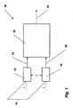
- an improved interferometer arrangement 30 is shown in Figure 2 .
- the interferometer arrangement 30 comprises an antenna array 32 which receives a plane wave 34 of electromagnetic radiation from a transmitter (not shown) located at an unknown angle, ⁇ , as before.
- the antenna array 32 comprises a plurality of antennas which receive the radiation of the plane wave 34. In this particular example, there are four antennas (not shown individually). Each antenna provides an output signal 36, 38, 40, 42 to a switching unit 44 which selects two of the output signals, say 38, 40, to pass to processor 46 for processing. Here, four pairs of signals from different antenna pairs are selected and passed to the processor for processing. Processor 46 processes the four pairs of signals and provides an output signal 48 which gives the value of ⁇ .
- switching unit 44 is not needed. This is because the signals received by the digital receiver can be combined in any way necessary to provide ⁇ .
- FIG. 3 illustrates one embodiment of an antenna array 32 in more detail.
- the array 32 includes four antennas 50, 52, 54, 56 arranged in a straight line.
- Each antenna 50, 52, 54, 56 may comprise a spiral antenna as described in EP-A-1 026 777 .
- any other suitable antenna can be used.
- Each antenna 50, 52, 54, 56 is spaced from its adjacent antennas such that the spacing between antenna 50 and antenna 54 is L 1 , the spacing between antenna 52 and antenna 56 is L 2 , the spacing between antenna 54 and antenna 56 is L 3 , and the spacing between antenna 50 and antenna 56 is L 4 .
- the choice of pairings is by way of example in this particular embodiment.
- L 1 , L 2 , L 3 and L 4 are chosen to be integral multiples of d 0 , that is:
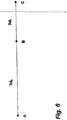
- a line of three antennas A, B, C is shown.
- Each pair of antennas A-B, B-C, A-C has an integer multiple of d 0 between them as shown, namely, 3 d 0 between A-B, 2 d 0 between B-C and 5 d 0 between A-C.
- M 3
- the same antennas may be used in more than one pair, but note that if the measurements are to be independent, it may be necessary to do one measurement a split second after another.
- k (5,2,3) T if the signals are processed from antenna pairs in the order A-C, B-C and A-B.
- the antenna coordinates are integral numbers of the separate unit distances in the x and y directions respectively.
- the choice of unit distances determines the frequency and unambiguous angle range in horizontal and vertical elevations.
- the next step is to determine the number of antennas to be used and the number of antenna pairs which are to be used to measure phase differences. It is not required to have a common reference antenna.
- a set of possible antenna meta x-coordinate spacings ⁇ K ⁇ is constructed.
- the term 'spacing' means the distance between antenna pairs selected to make a measurement. These are not the physical antenna x -coordinates but just a stage in the determination.
- the spacings have a highest common factor (HCF) of 1.
- HCF common factor
- a set of all possible y -coordinate spacings ⁇ K y ⁇ is constructed for the y -dimension. All values for x and y are excluded if they fall outside the maximum size of the array.
- MLE Maximum Likelihood Estimator
- values ⁇ 1 , ..., ⁇ M and ⁇ 1 , ..., ⁇ N are only known modulo 2 ⁇ , but since ⁇ j represents a phase difference of a virtual interferometer of unit distance, d 0 , then the value ⁇ j which is taken to lie in the interval [- ⁇ , ⁇ ), is the correct phase.
- the search can be limited to those k's with entries less than 100.
- the antenna array 32 of Figure 3 has been described as being one-dimensional, that is, a plurality of antennas spaced at different distances along the same straight line, the antenna array 32 may also comprise a plurality of antennas spaced at different distances in the same plane.
- the x- and y -component distances are integrals of the same unit spacing d 0 .
- Figure 8 illustrates a two-dimensional arrangement in which four antennas A, B, C, D are placed in a plane rather than a straight line with separations in the i and j directions which are integer multiples of d 0 as shown.
- antenna pair A-B are separated by m 1 d 0 in one direction and by m 2 d 0 in the other direction.
- antenna pair B-C are separated by m 3 d 0 and m 4 d 0 and antenna pair C-D by m 5 d 0 and m 6 d 0 .
- FIG. 9 a simplified example is shown in Figure 9 .
- four antennas A, B, C, D are shown in a plane with A and C being aligned in one direction and B and D being in another direction compared to the alignment direction of A and C.
- the integral separation is the same in the x and y directions. It may be difficult to obtain different angle and frequency ranges in the x and y directions.
- the matrix, K k 11 k 12 k 21 k 22 k 31 k 32 k 41 k 42
- K 2 1 4 1 9 1 3 ⁇ 1
- ⁇ 1 , ⁇ 2 , ⁇ 3 , ⁇ 4 are the measured phase differences between these antenna pairs.
- the hcf of the x and y column entries (i.e. non-zero) must be 1.
- ⁇ ⁇ x ⁇ T C x ⁇ 1 ⁇ x ⁇ T C x ⁇ 1 ⁇ x
- ⁇ ⁇ y ⁇ T C y ⁇ 1 ⁇ y ⁇ T C y ⁇ 1 ⁇
- C x A x RA x T
- C y A y RA y T
- R is the covariance matrix of the ⁇ i 's.
- estimators have variances 1 ⁇ T C x ⁇ 1 ⁇ and 1 ⁇ T C y ⁇ 1 ⁇ respectively.
- the present invention has been described with reference to one-dimensional and two-dimensional antenna arrays, it will be appreciated that the invention can also be extended to three-dimensional arrays.
- the antennas can be arranged in a non-planar array provided the boresight of each antenna is parallel.
- three matrices Q x , Q y and Q z need to be determined so that the three-dimensional array can be resolved into three orthogonal linear arrays having spacing vectors k x , k y and k z .
- the respective integer values of the vectors k x , k y and k z have the highest common factor of 1.
Landscapes
- Physics & Mathematics (AREA)
- Engineering & Computer Science (AREA)
- General Physics & Mathematics (AREA)
- Radar, Positioning & Navigation (AREA)
- Remote Sensing (AREA)
- Variable-Direction Aerials And Aerial Arrays (AREA)
Description
- The present invention relates to interferometers and is more particularly concerned with the measurement of angle of incidence of electromagnetic radiation incident on such an interferometer.
- It is known to use a pair of antennas to detect the location of an electromagnetic signal. The pair of antennas is arranged such that the spacing between the two antennas is such that the phase difference, φ, of the signals arriving at the antennas can be calculated using Bragg's law:-

- The phase difference of the incident electromagnetic signal at the two antennas can be measured and the location of the electromagnetic signal can then be determined from the angle at which the signals approach the two antennas using Bragg's law.
- However, the phase difference between the signals arriving at two antennas can only be measured modulo 2π. This means that for a phase difference of φ there may be more than one value that will satisfy Bragg's law thereby producing an ambiguous result. In order to overcome this problem, it is necessary to locate the pair of antennas sufficiently close so that no matter what angle, θ, at which the incident radiation arrives at the antennas, the phase difference would never exceed 2π. In order to do this, the phase difference, φ, must be kept in the interval [-π, π), such that

- For incident radiation having a frequency of less than 18GHz and an antenna specification where θ is limited such that |θ| <60°, then d = d 0 is 9.2mm as a suitable separation between the two antennas.
- However, whilst this is possible in theory, it is practically impossible for the antennas to be less than a few centimetres apart. This leads to ambiguity as to how many 2n are needed to add to the measured phase to get the correct measurement.
- It is therefore an object of the present invention to provide an interferometer arrangement which overcomes the problems mentioned above and provides unambiguous determinations of the angle of incidence of incident electromagnetic radiation.
- According to the invention, there is provided a method of determining relative positions of at least three antennas of an antenna array utilized in an interferometer arrangement according to claim 1.
- For a better understanding of the present invention, reference will now be made, by way of example only, to the accompanying drawings in which:-
-
Figure 1 is a schematic block diagram of conventional apparatus for determining the location of a radar or other incident electromagnetic radiation; -
Figure 2 is a schematic block diagram of apparatus for determining the location of a transmitter of electromagnetic radiation in accordance with the present invention; -
Figure 3 illustrates one embodiment of an antenna array for use in the apparatus ofFigure 2 ; -
Figure 4 illustrates the number of pairings from four antennas; -
Figure 5 illustrates the possible combinations for selecting four pairings for four antennas; -
Figure 6 illustrates a simplified embodiment of an antenna array in accordance with the present invention; -
Figure 7 illustrates Bragg's law for three dimensions where an antenna array is aligned in the x- y plane; -
Figure 8 illustrates a simplified drawing of a second embodiment of an antenna array for use in the apparatus ofFigure 2 ; and -
Figure 9 illustrates a second simplified embodiment of an antenna array in accordance with the present invention. - Referring initially to
Figure 1 , aconventional interferometer arrangement 10 is shown in which twoantennas antenna plane wave 16 of electromagnetic radiation being emitted from a transmitter (not shown) located at an unknown angle, θ. Eachantenna plane wave 16 at a particular frequency and hence wavelength, λ. - Each
antenna plane wave 16, produces anoutput signal processor 22 for processing.Processor 22 determines the unknown angle, θ, of the transmitter using Bragg's law:-
antenna antenna - If χ is the phase difference which is actually measured between the two antennas, then the errors can be expressed as follows:


- Deterministic errors refer to the phase measurement errors which have a non-zero mean between RF antenna channels and occurs where two channels of a M-channel RF switch is used with a systematic path difference in the switch. The present invention allows for sequential measurement of the antenna pair phase difference (two channel receiver) or simultaneous measurement of phase at each antenna (N-channel receiver) and the subtraction of the phases to form the phase differences. The choice of measurement scheme is reflected in the measurement covariance matrix R which is diagonal for the first case and non-diagonal for the second case.
- Non-deterministic errors refer to the phase measurement errors which have a zero mean between RF antenna channels. These errors would occur where the RF channels behind the antennas are perfectly matched, for example, matched cables and no path differences introduced by RF switches.
- In accordance with the present invention, an improved
interferometer arrangement 30 is shown inFigure 2 . Theinterferometer arrangement 30 comprises anantenna array 32 which receives aplane wave 34 of electromagnetic radiation from a transmitter (not shown) located at an unknown angle, θ, as before. Theantenna array 32 comprises a plurality of antennas which receive the radiation of theplane wave 34. In this particular example, there are four antennas (not shown individually). Each antenna provides anoutput signal switching unit 44 which selects two of the output signals, say 38, 40, to pass toprocessor 46 for processing. Here, four pairs of signals from different antenna pairs are selected and passed to the processor for processing.Processor 46 processes the four pairs of signals and provides anoutput signal 48 which gives the value of θ. - Alternatively, if a digital receiver is used to receive the signals, switching
unit 44 is not needed. This is because the signals received by the digital receiver can be combined in any way necessary to provide θ. -
Figure 3 illustrates one embodiment of anantenna array 32 in more detail. Thearray 32 includes fourantennas antenna EP-A-1 026 777 . Alternatively, any other suitable antenna can be used. - Each
antenna antenna 50 andantenna 54 is L1, the spacing betweenantenna 52 andantenna 56 is L2, the spacing betweenantenna 54 andantenna 56 is L3, and the spacing betweenantenna 50 andantenna 56 is L4. The choice of pairings is by way of example in this particular embodiment. - As discussed above, for radiation frequencies of less than 18GHz, the value of the spacing, d 0, between a pair of antennas which allows the phase to be unambiguously identified is 9.2mm. In accordance with the present invention, L1, L2, L3 and L4 are chosen to be integral multiples of d 0, that is:
- L 1 = k 1 d 0
- L 2 = k 2 d 0
- L 3 = k 3 d 0
- L 4 = k 4 d 0
- By combining measurements of phase difference between various pairs of antennas in
antenna array 32, a good estimate of the phase difference that would be measured between two antennas that had a separation distance d 0 can be obtained. This unambiguously gives the angle of arrival, θ. - However, it is to be noted that when choosing the values of k 1, k 2 , k 3 , k 4 the values must be physically realisable. One way of determining if the values of k 1, k 2, k 3, k 4 are physically realistic is by running through all possible values for k 1, k 2 , k 3, k 4 for each possible way of separating four antennas, and for each way, examining the different values of k 1, k 2 , k 3 , k 4 produced by picking different sets of pairs of antennas.
- For example, for the example shown in
Figure 3 , four pairs of antennas must be picked from the six possible choices as shown inFigure 4 . This gives 15 different ways of choosing four pairs of antennas as shown inFigure 5 . Of the 15 different choices shown, choices 1 to 6 can be considered as being
mirror images ofchoices 10 to 15 and therefore the choices can be limited to choices 1 to 9. - When an
antenna array 32 as described with reference toFigure 3 is utilised in theinterferometer arrangement 30, a plurality of virtual interferometers is formed. In order to describe how this works in more detail, a simpler antenna array having three antennas is illustrated inFigure 6 . - In
Figure 6 , a line of three antennas A, B, C is shown. Each pair of antennas A-B, B-C, A-C has an integer multiple of d0 between them as shown, namely, 3d0 between A-B, 2d0 between B-C and 5d0 between A-C. In this example, three virtual interferometers can be constructed and M=3. In
general, if there are several antennas in a line, it is necessary to identify M pairs of antennas and make M phase difference measurements between these pairs. The same antennas may be used in more than one pair, but note that if the measurements are to be independent, it may be necessary to do one measurement a split second after another. - In the example shown in
Figure 6 , k = (5,2,3) T if the signals are processed from antenna pairs in the order A-C, B-C and A-B. - In order to determine the positions of the antennas in a particular space, it is necessary to determine the maximum size allowed for the antenna array in the x and y directions. The antenna coordinates are integral numbers of the separate unit distances in the x and y directions respectively. The choice of unit distances determines the frequency and unambiguous angle range in horizontal and vertical elevations.
- The next step is to determine the number of antennas to be used and the number of antenna pairs which are to be used to measure phase differences. It is not required to have a common reference antenna. A set of possible antenna meta x-coordinate spacings {K} is constructed. The term 'spacing' means the distance between antenna pairs selected to make a measurement. These are not the physical antenna x-coordinates but just a stage in the determination. The spacings have a highest common factor (HCF) of 1.
Similarly, a set of all possible y-coordinate spacings {Ky} is constructed for the y-dimension. All values for x and y are excluded if they fall outside the maximum size of the array. - A set of physical spacing matrices {K =[KxKy]} is produced by iterating over all possible physical x - and y -antenna positions. From the set of possible K matrices and the set of possible meta x-coordinate spacings {K'x}, combinations are chosen which have a mapping matrix Qx which satisfies the condition QxKx = K'x and QxKy = 0. A candidate set is recorded in accordance with the candidate geometries (K,Qx). The candidate set is edited to remove mirror-image candidate geometries.
- A set of possible antenna meta y-coordinate spacings {K'y} are constructed. As before, these have HCF=1. From the candidate geometries (K,Qx) and the set of meta y-coordinate spacings {K'y}, combinations are chosen which have a mapping matrix Qy which satisfies the condition QyKy =K'y and QyKx =0. The candidate geometries (K,Qx,Qy) are recorded in the candidate set.
- For each geometry (K,Qx,Qy) in the candidate set, two matrices Px and Py are found which satisfy PxK'x = ξ and PyK'y = ξ where ξ is a column vector of all 1s. All entries without a solution are rejected and the candidate geometries (K,Qx,Qy,Px,Py ) are recorded in the candidate set.
- For each candidate antenna configuration, statistical measurement accuracy is calculated and the best candidate antenna configurations are selected for constructing the base plate of the antenna design.
- It is to be noted that the difference between a deterministic and non-deterministic design revolves around the calculation of the matrices (K,Qx,Qy,Px,Py ) with the condition that PxQxξ = o and PyQyξ = o where o is a column vector of zeros. The size of Qx, Qy, Px and Py is reduced by one column vector to accommodate this.
- In order to construct N virtual interferometers, where N ≤ M, a M x N matrix P is produced such that PT k = ξ where


- For example, when N = 3,


- Now if


- If the phase difference, ζm , associated with the mth virtual interferometer is defined as


where β = αd 0. - For example,

- Given measurements ζ 1,...,ζN , it is necessary to estimate β. It is possible to use the Maximum Likelihood Estimator (MLE), which is the value of β which maximises the joint density function given the measurements, that is, given


- If the estimate is β̂, then since C is symmetric

- Hence


- In the example above, if errors ε 1, ε 2 and ε 3 are independent, then R = σ 2 I and


- Therefore,


- It is to be noted that values χ 1, ..., χM and ζ 1, ..., ζN are only known modulo 2π, but since ζj represents a phase difference of a virtual interferometer of unit distance, d 0, then the value ζj which is taken to lie in the interval [-π, π), is the correct phase.
- If the correct number of 2π's are known to add onto χ̃j to make χj, then it would not be necessary to construct the ζj 's. The sole purpose of the ζj 's is to get over the problem of the 'lost' 2π's. If the correct number of 2π's is known to add to χ̃j to make χj , then ζ = PT χ and ξ = PT k .
- Hence


- In the case where M = N and P is a square matrix, then


- Furthermore, if the measurements are independent so that R = σ 2 I then
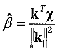

- For example


- If nullifying deterministic error has to be considered, then P will be forced not to be a square matrix.
- β̂ is always an unbiased estimator, no matter how k and P are chosen. So the problem is to find k and P that minimises

- It may seem, by the expression on the right hand side that E(β̂-β)2 does not depend on k, since ξ = (1, 1, ..., 1) T and C = PTRP, but different choices of k allow different choices of P, so E(β̂-β)2 must be minimised over all possible k and P.
- k is chosen such that hcf(k 1, ..., km ) = C where C is the largest positive integer to divide ki for every i = 1, ..., M. In forming a column of P, a vector p = (p 1, ..., pm ) T must be found such that k T p = 1, that is, for M linearly independent vectors p 1, ..., p m , p 1 T k = p 2 T k = ... = p m T k = 1. However, it can be shown that this is only valid if and only if hcf(k 1, ..., km ) = 1.
- As the possible choices of k and P are searched to minimise the variance, E(β̂ - β)2 , it is only necessary to search through k = (k 1, ..., kM ) T with hcf(k 1, ..., kM )=1.
- In the case where Δ, the deterministic error is zero, it is possible to find M linearly independent vectors p 1, ..., p M such that p m T k = 1 for all M. This means that P can be made into a square MxM matrix,

- If Δ ≠ 0, it is always possible find M - 1 linearly independent vectors and never any more, such that p m T k = 1 and p m T ξ' = 0 for all m. The extra condition p m T ξ' = 0 has reduced the number of linearly independent vectors that can be found by one. Now P is a Mx(M - 1) matrix and

- If the antennas are to be fixed into a relatively small space, for example taking up no more than about 50 to 100cm, the search can be limited to those k's with entries less than 100.
- Whilst the
antenna array 32 ofFigure 3 has been described as being one-dimensional, that is, a plurality of antennas spaced at different distances along the same straight line, theantenna array 32 may also comprise a plurality of antennas spaced at different distances in the same plane. - Before describing a specific embodiment of such a two-dimensional or planar arrangement, Bragg's law in two dimensions will be discussed with reference to
Figure 7 . - In
Figure 7 , a plane wave is shown incident on a pair of antennas lying in the x-y plane which are spaced apart by a distance vector d = dx i + dy j . The x- and y-component distances are integrals of the same unit spacing d 0. The plane wave arrives in a direction described by the unit vector v̂ = (vx , vy , vz ) T in three dimensions. The phase difference, in two dimensions, experienced between the two antennas is


- If two antennas are separated by distance vector d, then, χ, the phase difference measured between the two antennas, satisfies

-
Figure 8 illustrates a two-dimensional arrangement in which four antennas A, B, C, D are placed in a plane rather than a straight line with separations in the i and j directions which are integer multiples of d 0 as shown. In the illustrated example, antenna pair A-B are separated by m 1 d 0 in one direction and by m 2 d 0 in the other direction. Similarly, antenna pair B-C are separated by m 3 d 0 and m 4 d 0 and antenna pair C-D by m 5 d 0 and m 6 d 0. - In order to describe how such a two-dimensional antenna array works, a simplified example is shown in
Figure 9 . Again, four antennas A, B, C, D are shown in a plane with A and C being aligned in one direction and B and D being in another direction compared to the alignment direction of A and C. Here, the integral separation is the same in the x and y directions. It may be difficult to obtain different angle and frequency ranges in the x and y directions. If the separation in the x and y direction respectively is k j1, k j2 between the antennas of the jth pair, then the matrix, K, defining these separations can be expressed as:-
- Using the antenna pairs of A-B, C-D, A-D and B-C, K can be populated for the example in
Figure 9 as follows:-
- If χ 1, χ 2, χ 3 , χ 4 are the measured phase differences between these antenna pairs, then the matrix of these phase differences can be expressed as χ = (χ 1, χ 2, χ 3 , χ 4) T and the matrix of the phase measurement error as ε = (ε 1, ε 2, ε 3, ε 4) T. It then follows that


Figure 9 . - To determine φx and φy, two Nx4 matrices, Qx and Qy need to be determined so that the rows of Qx and Qy are linearly independent such that
[QxK] i2 = 0 for all i = 1,...,N
[QyK] i1 = 0 for all i = 1,...,N - The reason for the requirement of linearly independent rows is so that no singular covariance matrices are formed. In this case,

- Hence

- In order to use the same method as for a linear array, the hcf of the x and y column entries (i.e. non-zero) must be 1.
- Applying Qx and Qy to the phase differences, χ, which have been measured gives:


- For example,

- Then it is necessary to find Px, Py which are N × N invertible matrices with integer entries such that


- If ζ x = PxQx χ , ζ y = PyQy χ , Ax = PxQx and Ay = PyQy then


- For example


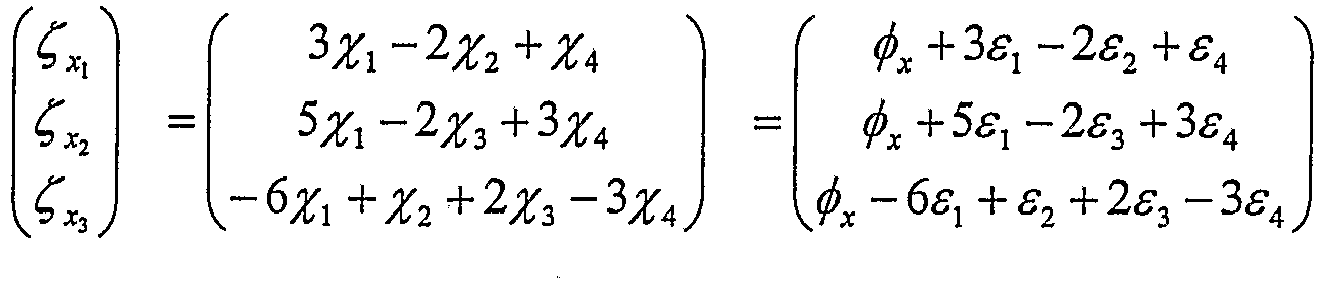

- Like the one-dimensional case, it is possible to start out with measurements χ̃j which are a multiple of 2π out from their true value χj. However, in creating linear multiples ζ x
1 , ζ x2 , ζ x3 which are estimating the value φx, which lies in the range [-π, π), it is possible to overcome this problem by recording ζ̃ x1 , ζ̃ x2 , ζ̃ x3 , modulo 2π. - Now it is possible to use the techniques of the one-dimensional case to provide estimates φ̂x, φ̂y for φx and φy .
Compare the 1-D equations ζ = βξ + PT ε to the 2-D equations ζ x = φ x ξ + Ax ε ζ y = φy ξ + Ay ε - Hence the estimators for the 2-D case are:


- These estimators have variances


- In estimating φx and φy , estimates are also obtained for vx and vy, since


- It is to be noted that the errors for φx and φy are not independent and that they have a degree of covariance. This covariance can be calculated and allowed for but this is not described in detail here.
- Whilst the present invention has been described with reference to one-dimensional and two-dimensional antenna arrays, it will be appreciated that the invention can also be extended to three-dimensional arrays. The antennas can be arranged in a non-planar array provided the boresight of each antenna is parallel. Here, in order to determine φx , φy and φz , three matrices Qx, Qy and Qz need to be determined so that the three-dimensional array can be resolved into three orthogonal linear arrays having spacing vectors k x , k y and k z . The respective integer values of the vectors k x , k y and k z have the highest common factor of 1.
- In the three-dimensional case, it is possible to measure both angle of arrival and frequency of the incident radiation simultaneously.
- It will also be appreciated that, whilst the invention has been described with reference to antenna arrays having three and four antennas, the invention is not limited to such numbers and any suitable number of antennas may be used in the antenna array provided the spacing requirements discussed above are met.
Claims (1)
- A method of determining relative positions of at least three antennas of an antenna array utilized in an interferometer arrangement, the antenna array arranged to receive a plane wave of electromagnetic radiation from a transmitter located at an unknown angle; each of the antenna being spaced from one another in an x dimension and a y dimension, the x and y dimensions being orthogonal; the method comprising the steps of:a) determining a maximum size allowed for the antenna array in the x dimension and the y dimension;b) determining the number of antennas and number of antenna pairs to be used for receiving the plane wave of electromagnetic radiation and making phase difference measurements;c) selecting a unit spacing for each of the x and y dimensions determined by the frequency of the electromagnetic radiation to be received and the unambiguous angle range desired in each of the x and y dimensions;d) producing a set of physical spacing matrices {K} where K = [Kx Ky ] and Kx and Ky are the respective x- and y-coordinate spacings; the integer values of Kx and Ky representing multiples of the unit spacing for the respective x and y dimensions; and where producing the set of physical spacing matrices includes iterating over all possible physical x- and y- coordinates;e) determining sets {K'x } and {K'y} of meta x-coordinate spacings and meta y-coordinate spacings respectively, such that: highest common factor of the spacings of each K'x is 1; highest common factor of the spacings of each K'y is 1;f) deriving a set of candidate geometries (K,Qx,Qy) by finding combinations of K, K'x and K'y which have respective integer mapping matrixes Ox, Qy such that respective integer mapping matrices Ox and Oy applied to the physical spacings Kx and Ky satisfy QxKx =K'x and QxKy =0, and QyKy = K'y and QyKx = 0;g) for each candidate geometry, analysing candidates of the candidate set to identify a preferred physical arrangement of the plurality of antennas in the antenna array, comprising:(i) finding matrices Px and Py such that PxK'x = ξ and PyK'y= ξ, where ξ is a column vector of all ones(ii) rejecting candidates of the set with no solution; and(iii) recording candidate geometries (K,Qx,Qy,Px,Py) in the candidate set;(iv) for each candidate antenna geometry, statistical measurement accuracy is calculated and(v) select the best candidate antenna geometries for constructing a base plate of the antenna array.
Priority Applications (1)
| Application Number | Priority Date | Filing Date | Title |
|---|---|---|---|
| PL15173452T PL2977783T3 (en) | 2003-04-10 | 2004-04-06 | Interferometers |
Applications Claiming Priority (4)
| Application Number | Priority Date | Filing Date | Title |
|---|---|---|---|
| EP03252273 | 2003-04-10 | ||
| GB0308265A GB0308265D0 (en) | 2003-04-10 | 2003-04-10 | Interferometers |
| PCT/GB2004/001500 WO2004090567A1 (en) | 2003-04-10 | 2004-04-06 | Interferometers |
| EP04725958A EP1611455A1 (en) | 2003-04-10 | 2004-04-06 | Interferometers |
Related Parent Applications (1)
| Application Number | Title | Priority Date | Filing Date |
|---|---|---|---|
| EP04725958A Division EP1611455A1 (en) | 2003-04-10 | 2004-04-06 | Interferometers |
Publications (2)
| Publication Number | Publication Date |
|---|---|
| EP2977783A1 EP2977783A1 (en) | 2016-01-27 |
| EP2977783B1 true EP2977783B1 (en) | 2020-06-24 |
Family
ID=33161018
Family Applications (2)
| Application Number | Title | Priority Date | Filing Date |
|---|---|---|---|
| EP15173452.2A Expired - Lifetime EP2977783B1 (en) | 2003-04-10 | 2004-04-06 | Interferometers |
| EP04725958A Ceased EP1611455A1 (en) | 2003-04-10 | 2004-04-06 | Interferometers |
Family Applications After (1)
| Application Number | Title | Priority Date | Filing Date |
|---|---|---|---|
| EP04725958A Ceased EP1611455A1 (en) | 2003-04-10 | 2004-04-06 | Interferometers |
Country Status (5)
| Country | Link |
|---|---|
| US (1) | US7026990B2 (en) |
| EP (2) | EP2977783B1 (en) |
| ES (1) | ES2812572T3 (en) |
| PL (1) | PL2977783T3 (en) |
| WO (1) | WO2004090567A1 (en) |
Families Citing this family (14)
| Publication number | Priority date | Publication date | Assignee | Title |
|---|---|---|---|---|
| KR101244440B1 (en) | 2004-07-02 | 2013-03-18 | 트랙맨 에이/에스 | A method and an apparatus for determining a deviation between an actual direction of a launched projectile and a predetermined direction |
| EP2113783B1 (en) * | 2005-02-17 | 2011-09-28 | Fujitsu Limited | Incoming direction estimation apparatus |
| US10393870B2 (en) | 2005-03-03 | 2019-08-27 | Trackman A/S | Determination of spin parameters of a sports ball |
| US7755533B2 (en) * | 2006-11-01 | 2010-07-13 | Imsar Llc | Interferometric switched beam radar apparatus and method |
| KR102033703B1 (en) | 2009-01-29 | 2019-10-17 | 트랙맨 에이/에스 | An assembly comprising a radar and an imaging element |
| EP2605036B1 (en) * | 2011-12-16 | 2019-10-23 | Trackman A/S | A method and a sensor for determining a direction-of-arrival of impingent radiation |
| FR3000221B1 (en) * | 2012-12-21 | 2019-07-12 | Thales | SYSTEM FOR DETERMINING AN ARRIVAL DIRECTION |
| KR101640787B1 (en) * | 2015-05-12 | 2016-07-19 | 국방과학연구소 | The system for finding direction of a wireless signal |
| US10379214B2 (en) | 2016-07-11 | 2019-08-13 | Trackman A/S | Device, system and method for tracking multiple projectiles |
| US10444339B2 (en) | 2016-10-31 | 2019-10-15 | Trackman A/S | Skid and roll tracking system |
| US10989791B2 (en) | 2016-12-05 | 2021-04-27 | Trackman A/S | Device, system, and method for tracking an object using radar data and imager data |
| US11486996B2 (en) * | 2017-09-25 | 2022-11-01 | Hitachi Astemo, Ltd. | Radar device and antenna device |
| US20200037181A1 (en) * | 2018-07-30 | 2020-01-30 | Rohde & Schwarz Gmbh & Co. Kg | Radio frequency test system, measurement setup as well as method for testing a device under test |
| CN113050030B (en) * | 2021-03-26 | 2021-11-05 | 江苏蓝策电子科技有限公司 | Positioning method and device based on angle of arrival ranging |
Family Cites Families (14)
| Publication number | Priority date | Publication date | Assignee | Title |
|---|---|---|---|---|
| GB1191831A (en) | 1965-12-21 | 1970-05-13 | Mullard Ltd | Radio Interferometer System |
| JPS5210633B1 (en) | 1968-09-05 | 1977-03-25 | ||
| US3806930A (en) | 1969-12-23 | 1974-04-23 | Siemens Ag | Method and apparatus for electronically controlling the pattern of a phased array antenna |
| GB1296296A (en) | 1971-06-23 | 1972-11-15 | ||
| GB1401273A (en) | 1971-06-30 | 1975-07-16 | Cossor Ltd A C | Secondary radar receiver system |
| GB1337099A (en) | 1972-05-17 | 1973-11-14 | ||
| GB1540418A (en) | 1976-03-15 | 1979-02-14 | Mullard Ltd | Resolving angular ambiguity |
| GB2147760B (en) | 1983-10-07 | 1987-04-15 | Racal Res Ltd | Direction finding systems |
| US4975710A (en) * | 1989-08-01 | 1990-12-04 | Baghdady Elie J | Methods and apparatus for direction of arrival measurement and radio navigation aids |
| DE4425661A1 (en) * | 1994-07-20 | 1996-01-25 | Daimler Benz Aerospace Ag | Large base interferometer direction finder system |
| DE19511752A1 (en) * | 1995-03-30 | 1996-10-10 | Siemens Ag | Process for high-resolution evaluation of signals for one- or two-dimensional direction or frequency estimation |
| GB2345798A (en) | 1999-01-15 | 2000-07-19 | Marconi Electronic Syst Ltd | Broadband antennas |
| US6313794B1 (en) * | 2000-01-19 | 2001-11-06 | Litton Systems, Inc. | Method of detection and determining an angular location of frequency agile emitters |
| US6377214B1 (en) * | 2000-08-04 | 2002-04-23 | Trw Inc. | Pipelined processing algorithm for interferometer angle of arrival estimation |
-
2004
- 2004-04-06 PL PL15173452T patent/PL2977783T3/en unknown
- 2004-04-06 EP EP15173452.2A patent/EP2977783B1/en not_active Expired - Lifetime
- 2004-04-06 WO PCT/GB2004/001500 patent/WO2004090567A1/en not_active Ceased
- 2004-04-06 EP EP04725958A patent/EP1611455A1/en not_active Ceased
- 2004-04-06 ES ES15173452T patent/ES2812572T3/en not_active Expired - Lifetime
- 2004-05-24 US US10/852,048 patent/US7026990B2/en not_active Expired - Lifetime
Non-Patent Citations (1)
| Title |
|---|
| None * |
Also Published As
| Publication number | Publication date |
|---|---|
| WO2004090567A1 (en) | 2004-10-21 |
| ES2812572T3 (en) | 2021-03-17 |
| EP1611455A1 (en) | 2006-01-04 |
| US7026990B2 (en) | 2006-04-11 |
| PL2977783T3 (en) | 2020-12-14 |
| EP2977783A1 (en) | 2016-01-27 |
| US20050052316A1 (en) | 2005-03-10 |
Similar Documents
| Publication | Publication Date | Title |
|---|---|---|
| CN110297236B (en) | radar device | |
| AU2022259835B2 (en) | Direction of arrival estimation | |
| CN110286376B (en) | radar device | |
| CN106546983B (en) | Radar apparatus | |
| EP2977783A1 (en) | Interferometers | |
| US5574468A (en) | Phase-equivalent interferometer arrays | |
| US6914559B2 (en) | Direction finding method and system using digital directional correlators | |
| JP6755121B2 (en) | Radar device | |
| JP6801214B2 (en) | MIMO radar device and vehicle | |
| CN110073237A (en) | MIMO radar sensor for motor vehicle | |
| EP1118870A2 (en) | Low cost angle of arrival measurement system | |
| CN111405657B (en) | CSI-based single access point positioning method based on arrival angle and arrival time difference | |
| KR20200001534A (en) | Radar and antenna built in radar | |
| JP2019511160A (en) | Correlated fan beam forming machine | |
| WO2011162808A1 (en) | Receiving station and methods for determining an aoa of short-duration signals using saw devices | |
| US6377214B1 (en) | Pipelined processing algorithm for interferometer angle of arrival estimation | |
| JP3477132B2 (en) | Arrival azimuth measuring device for incoming wave | |
| EP3516412B1 (en) | Apparatus for estimating a direction of arrival and corresponding method | |
| Johnson et al. | Comparison of superresolution algorithms for radio direction finding | |
| Cao et al. | Direction of arrival estimation for monostatic multiple-input multiple-output radar with arbitrary array structures | |
| KR101958337B1 (en) | The method and apparatus for estimating the direction of arrival of a signal | |
| CN113270729B (en) | Three-dimensional array antenna, positioning method and system, BLE chip and wireless MCU chip | |
| Tang et al. | Iteratively reweighted lp norm minimization for DOD and DOA estimation in bistatic MIMO radar under impulsive noise | |
| Chen et al. | Computationally efficient ambiguity‐free two‐dimensional DOA estimation method for coprime planar array: RD‐Root‐MUSIC Algorithm | |
| KR102415269B1 (en) | Radar and antenna built in radar |
Legal Events
| Date | Code | Title | Description |
|---|---|---|---|
| PUAI | Public reference made under article 153(3) epc to a published international application that has entered the european phase |
Free format text: ORIGINAL CODE: 0009012 |
|
| AC | Divisional application: reference to earlier application |
Ref document number: 1611455 Country of ref document: EP Kind code of ref document: P |
|
| AK | Designated contracting states |
Kind code of ref document: A1 Designated state(s): AT BE BG CH CY CZ DE DK EE ES FI FR GB GR HU IE IT LI LU MC NL PL PT RO SE SI SK TR |
|
| 17P | Request for examination filed |
Effective date: 20160726 |
|
| RBV | Designated contracting states (corrected) |
Designated state(s): AT BE BG CH CY CZ DE DK EE ES FI FR GB GR HU IE IT LI LU MC NL PL PT RO SE SI SK TR |
|
| RAP1 | Party data changed (applicant data changed or rights of an application transferred) |
Owner name: LEONARDO MW LTD |
|
| STAA | Information on the status of an ep patent application or granted ep patent |
Free format text: STATUS: EXAMINATION IS IN PROGRESS |
|
| 17Q | First examination report despatched |
Effective date: 20180309 |
|
| GRAP | Despatch of communication of intention to grant a patent |
Free format text: ORIGINAL CODE: EPIDOSNIGR1 |
|
| STAA | Information on the status of an ep patent application or granted ep patent |
Free format text: STATUS: GRANT OF PATENT IS INTENDED |
|
| INTG | Intention to grant announced |
Effective date: 20200302 |
|
| GRAS | Grant fee paid |
Free format text: ORIGINAL CODE: EPIDOSNIGR3 |
|
| GRAA | (expected) grant |
Free format text: ORIGINAL CODE: 0009210 |
|
| STAA | Information on the status of an ep patent application or granted ep patent |
Free format text: STATUS: THE PATENT HAS BEEN GRANTED |
|
| AC | Divisional application: reference to earlier application |
Ref document number: 1611455 Country of ref document: EP Kind code of ref document: P |
|
| AK | Designated contracting states |
Kind code of ref document: B1 Designated state(s): AT BE BG CH CY CZ DE DK EE ES FI FR GB GR HU IE IT LI LU MC NL PL PT RO SE SI SK TR |
|
| REG | Reference to a national code |
Ref country code: GB Ref legal event code: FG4D |
|
| REG | Reference to a national code |
Ref country code: CH Ref legal event code: EP |
|
| REG | Reference to a national code |
Ref country code: DE Ref legal event code: R096 Ref document number: 602004054705 Country of ref document: DE |
|
| REG | Reference to a national code |
Ref country code: AT Ref legal event code: REF Ref document number: 1284419 Country of ref document: AT Kind code of ref document: T Effective date: 20200715 |
|
| REG | Reference to a national code |
Ref country code: IE Ref legal event code: FG4D |
|
| REG | Reference to a national code |
Ref country code: CH Ref legal event code: NV Representative=s name: DR. GRAF AND PARTNER AG INTELLECTUAL PROPERTY, CH |
|
| REG | Reference to a national code |
Ref country code: SE Ref legal event code: TRGR |
|
| PG25 | Lapsed in a contracting state [announced via postgrant information from national office to epo] |
Ref country code: FI Free format text: LAPSE BECAUSE OF FAILURE TO SUBMIT A TRANSLATION OF THE DESCRIPTION OR TO PAY THE FEE WITHIN THE PRESCRIBED TIME-LIMIT Effective date: 20200624 Ref country code: GR Free format text: LAPSE BECAUSE OF FAILURE TO SUBMIT A TRANSLATION OF THE DESCRIPTION OR TO PAY THE FEE WITHIN THE PRESCRIBED TIME-LIMIT Effective date: 20200925 |
|
| PG25 | Lapsed in a contracting state [announced via postgrant information from national office to epo] |
Ref country code: BG Free format text: LAPSE BECAUSE OF FAILURE TO SUBMIT A TRANSLATION OF THE DESCRIPTION OR TO PAY THE FEE WITHIN THE PRESCRIBED TIME-LIMIT Effective date: 20200924 |
|
| REG | Reference to a national code |
Ref country code: NL Ref legal event code: MP Effective date: 20200624 |
|
| REG | Reference to a national code |
Ref country code: AT Ref legal event code: MK05 Ref document number: 1284419 Country of ref document: AT Kind code of ref document: T Effective date: 20200624 |
|
| PG25 | Lapsed in a contracting state [announced via postgrant information from national office to epo] |
Ref country code: NL Free format text: LAPSE BECAUSE OF FAILURE TO SUBMIT A TRANSLATION OF THE DESCRIPTION OR TO PAY THE FEE WITHIN THE PRESCRIBED TIME-LIMIT Effective date: 20200624 |
|
| PG25 | Lapsed in a contracting state [announced via postgrant information from national office to epo] |
Ref country code: RO Free format text: LAPSE BECAUSE OF FAILURE TO SUBMIT A TRANSLATION OF THE DESCRIPTION OR TO PAY THE FEE WITHIN THE PRESCRIBED TIME-LIMIT Effective date: 20200624 Ref country code: EE Free format text: LAPSE BECAUSE OF FAILURE TO SUBMIT A TRANSLATION OF THE DESCRIPTION OR TO PAY THE FEE WITHIN THE PRESCRIBED TIME-LIMIT Effective date: 20200624 Ref country code: CZ Free format text: LAPSE BECAUSE OF FAILURE TO SUBMIT A TRANSLATION OF THE DESCRIPTION OR TO PAY THE FEE WITHIN THE PRESCRIBED TIME-LIMIT Effective date: 20200624 Ref country code: AT Free format text: LAPSE BECAUSE OF FAILURE TO SUBMIT A TRANSLATION OF THE DESCRIPTION OR TO PAY THE FEE WITHIN THE PRESCRIBED TIME-LIMIT Effective date: 20200624 Ref country code: PT Free format text: LAPSE BECAUSE OF FAILURE TO SUBMIT A TRANSLATION OF THE DESCRIPTION OR TO PAY THE FEE WITHIN THE PRESCRIBED TIME-LIMIT Effective date: 20201026 |
|
| PG25 | Lapsed in a contracting state [announced via postgrant information from national office to epo] |
Ref country code: SK Free format text: LAPSE BECAUSE OF FAILURE TO SUBMIT A TRANSLATION OF THE DESCRIPTION OR TO PAY THE FEE WITHIN THE PRESCRIBED TIME-LIMIT Effective date: 20200624 |
|
| REG | Reference to a national code |
Ref country code: ES Ref legal event code: FG2A Ref document number: 2812572 Country of ref document: ES Kind code of ref document: T3 Effective date: 20210317 |
|
| REG | Reference to a national code |
Ref country code: DE Ref legal event code: R097 Ref document number: 602004054705 Country of ref document: DE |
|
| PG25 | Lapsed in a contracting state [announced via postgrant information from national office to epo] |
Ref country code: DK Free format text: LAPSE BECAUSE OF FAILURE TO SUBMIT A TRANSLATION OF THE DESCRIPTION OR TO PAY THE FEE WITHIN THE PRESCRIBED TIME-LIMIT Effective date: 20200624 |
|
| PLBE | No opposition filed within time limit |
Free format text: ORIGINAL CODE: 0009261 |
|
| STAA | Information on the status of an ep patent application or granted ep patent |
Free format text: STATUS: NO OPPOSITION FILED WITHIN TIME LIMIT |
|
| 26N | No opposition filed |
Effective date: 20210325 |
|
| REG | Reference to a national code |
Ref country code: DE Ref legal event code: R082 Ref document number: 602004054705 Country of ref document: DE Representative=s name: MANITZ FINSTERWALD PATENT- UND RECHTSANWALTSPA, DE Ref country code: DE Ref legal event code: R081 Ref document number: 602004054705 Country of ref document: DE Owner name: LEONARDO UK LTD, GB Free format text: FORMER OWNER: LEONARDO MW LTD., BASILDON, ESSEX, GB |
|
| PG25 | Lapsed in a contracting state [announced via postgrant information from national office to epo] |
Ref country code: SI Free format text: LAPSE BECAUSE OF FAILURE TO SUBMIT A TRANSLATION OF THE DESCRIPTION OR TO PAY THE FEE WITHIN THE PRESCRIBED TIME-LIMIT Effective date: 20200624 |
|
| PG25 | Lapsed in a contracting state [announced via postgrant information from national office to epo] |
Ref country code: MC Free format text: LAPSE BECAUSE OF FAILURE TO SUBMIT A TRANSLATION OF THE DESCRIPTION OR TO PAY THE FEE WITHIN THE PRESCRIBED TIME-LIMIT Effective date: 20200624 |
|
| PG25 | Lapsed in a contracting state [announced via postgrant information from national office to epo] |
Ref country code: LU Free format text: LAPSE BECAUSE OF NON-PAYMENT OF DUE FEES Effective date: 20210406 |
|
| REG | Reference to a national code |
Ref country code: BE Ref legal event code: MM Effective date: 20210430 |
|
| PG25 | Lapsed in a contracting state [announced via postgrant information from national office to epo] |
Ref country code: IE Free format text: LAPSE BECAUSE OF NON-PAYMENT OF DUE FEES Effective date: 20210406 |
|
| PG25 | Lapsed in a contracting state [announced via postgrant information from national office to epo] |
Ref country code: BE Free format text: LAPSE BECAUSE OF NON-PAYMENT OF DUE FEES Effective date: 20210430 |
|
| PG25 | Lapsed in a contracting state [announced via postgrant information from national office to epo] |
Ref country code: HU Free format text: LAPSE BECAUSE OF FAILURE TO SUBMIT A TRANSLATION OF THE DESCRIPTION OR TO PAY THE FEE WITHIN THE PRESCRIBED TIME-LIMIT; INVALID AB INITIO Effective date: 20040406 Ref country code: CY Free format text: LAPSE BECAUSE OF FAILURE TO SUBMIT A TRANSLATION OF THE DESCRIPTION OR TO PAY THE FEE WITHIN THE PRESCRIBED TIME-LIMIT Effective date: 20200624 |
|
| PGFP | Annual fee paid to national office [announced via postgrant information from national office to epo] |
Ref country code: PL Payment date: 20230323 Year of fee payment: 20 |
|
| PGFP | Annual fee paid to national office [announced via postgrant information from national office to epo] |
Ref country code: IT Payment date: 20230420 Year of fee payment: 20 Ref country code: FR Payment date: 20230424 Year of fee payment: 20 Ref country code: ES Payment date: 20230627 Year of fee payment: 20 Ref country code: DE Payment date: 20220620 Year of fee payment: 20 Ref country code: CH Payment date: 20230502 Year of fee payment: 20 |
|
| PGFP | Annual fee paid to national office [announced via postgrant information from national office to epo] |
Ref country code: TR Payment date: 20230404 Year of fee payment: 20 Ref country code: SE Payment date: 20230420 Year of fee payment: 20 |
|
| PGFP | Annual fee paid to national office [announced via postgrant information from national office to epo] |
Ref country code: GB Payment date: 20230419 Year of fee payment: 20 |
|
| REG | Reference to a national code |
Ref country code: DE Ref legal event code: R071 Ref document number: 602004054705 Country of ref document: DE |
|
| REG | Reference to a national code |
Ref country code: CH Ref legal event code: PL |
|
| REG | Reference to a national code |
Ref country code: GB Ref legal event code: PE20 Expiry date: 20240405 |
|
| REG | Reference to a national code |
Ref country code: ES Ref legal event code: FD2A Effective date: 20240506 |
|
| REG | Reference to a national code |
Ref country code: SE Ref legal event code: EUG |
|
| PG25 | Lapsed in a contracting state [announced via postgrant information from national office to epo] |
Ref country code: GB Free format text: LAPSE BECAUSE OF EXPIRATION OF PROTECTION Effective date: 20240405 |
|
| PG25 | Lapsed in a contracting state [announced via postgrant information from national office to epo] |
Ref country code: ES Free format text: LAPSE BECAUSE OF EXPIRATION OF PROTECTION Effective date: 20240407 |
|
| PG25 | Lapsed in a contracting state [announced via postgrant information from national office to epo] |
Ref country code: GB Free format text: LAPSE BECAUSE OF EXPIRATION OF PROTECTION Effective date: 20240405 Ref country code: ES Free format text: LAPSE BECAUSE OF EXPIRATION OF PROTECTION Effective date: 20240407 |