EP2977747A1 - Method and apparatus for testing materials - Google Patents
Method and apparatus for testing materials Download PDFInfo
- Publication number
- EP2977747A1 EP2977747A1 EP15176715.9A EP15176715A EP2977747A1 EP 2977747 A1 EP2977747 A1 EP 2977747A1 EP 15176715 A EP15176715 A EP 15176715A EP 2977747 A1 EP2977747 A1 EP 2977747A1
- Authority
- EP
- European Patent Office
- Prior art keywords
- composite
- infrared
- sample
- testing
- aircraft
- Prior art date
- Legal status (The legal status is an assumption and is not a legal conclusion. Google has not performed a legal analysis and makes no representation as to the accuracy of the status listed.)
- Withdrawn
Links
Images


Classifications
-
- G—PHYSICS
- G01—MEASURING; TESTING
- G01J—MEASUREMENT OF INTENSITY, VELOCITY, SPECTRAL CONTENT, POLARISATION, PHASE OR PULSE CHARACTERISTICS OF INFRARED, VISIBLE OR ULTRAVIOLET LIGHT; COLORIMETRY; RADIATION PYROMETRY
- G01J3/00—Spectrometry; Spectrophotometry; Monochromators; Measuring colours
- G01J3/02—Details
- G01J3/0297—Constructional arrangements for removing other types of optical noise or for performing calibration
-
- G—PHYSICS
- G01—MEASURING; TESTING
- G01N—INVESTIGATING OR ANALYSING MATERIALS BY DETERMINING THEIR CHEMICAL OR PHYSICAL PROPERTIES
- G01N21/00—Investigating or analysing materials by the use of optical means, i.e. using sub-millimetre waves, infrared, visible or ultraviolet light
- G01N21/17—Systems in which incident light is modified in accordance with the properties of the material investigated
- G01N21/25—Colour; Spectral properties, i.e. comparison of effect of material on the light at two or more different wavelengths or wavelength bands
- G01N21/27—Colour; Spectral properties, i.e. comparison of effect of material on the light at two or more different wavelengths or wavelength bands using photo-electric detection ; circuits for computing concentration
- G01N21/274—Calibration, base line adjustment, drift correction
-
- G—PHYSICS
- G01—MEASURING; TESTING
- G01J—MEASUREMENT OF INTENSITY, VELOCITY, SPECTRAL CONTENT, POLARISATION, PHASE OR PULSE CHARACTERISTICS OF INFRARED, VISIBLE OR ULTRAVIOLET LIGHT; COLORIMETRY; RADIATION PYROMETRY
- G01J3/00—Spectrometry; Spectrophotometry; Monochromators; Measuring colours
- G01J3/28—Investigating the spectrum
-
- G—PHYSICS
- G01—MEASURING; TESTING
- G01N—INVESTIGATING OR ANALYSING MATERIALS BY DETERMINING THEIR CHEMICAL OR PHYSICAL PROPERTIES
- G01N21/00—Investigating or analysing materials by the use of optical means, i.e. using sub-millimetre waves, infrared, visible or ultraviolet light
- G01N21/17—Systems in which incident light is modified in accordance with the properties of the material investigated
- G01N21/25—Colour; Spectral properties, i.e. comparison of effect of material on the light at two or more different wavelengths or wavelength bands
- G01N21/31—Investigating relative effect of material at wavelengths characteristic of specific elements or molecules, e.g. atomic absorption spectrometry
- G01N21/35—Investigating relative effect of material at wavelengths characteristic of specific elements or molecules, e.g. atomic absorption spectrometry using infrared light
- G01N21/3563—Investigating relative effect of material at wavelengths characteristic of specific elements or molecules, e.g. atomic absorption spectrometry using infrared light for analysing solids; Preparation of samples therefor
-
- G—PHYSICS
- G01—MEASURING; TESTING
- G01N—INVESTIGATING OR ANALYSING MATERIALS BY DETERMINING THEIR CHEMICAL OR PHYSICAL PROPERTIES
- G01N21/00—Investigating or analysing materials by the use of optical means, i.e. using sub-millimetre waves, infrared, visible or ultraviolet light
- G01N21/17—Systems in which incident light is modified in accordance with the properties of the material investigated
- G01N21/25—Colour; Spectral properties, i.e. comparison of effect of material on the light at two or more different wavelengths or wavelength bands
- G01N21/31—Investigating relative effect of material at wavelengths characteristic of specific elements or molecules, e.g. atomic absorption spectrometry
- G01N21/35—Investigating relative effect of material at wavelengths characteristic of specific elements or molecules, e.g. atomic absorption spectrometry using infrared light
- G01N2021/3595—Investigating relative effect of material at wavelengths characteristic of specific elements or molecules, e.g. atomic absorption spectrometry using infrared light using FTIR
-
- G—PHYSICS
- G01—MEASURING; TESTING
- G01N—INVESTIGATING OR ANALYSING MATERIALS BY DETERMINING THEIR CHEMICAL OR PHYSICAL PROPERTIES
- G01N21/00—Investigating or analysing materials by the use of optical means, i.e. using sub-millimetre waves, infrared, visible or ultraviolet light
- G01N21/84—Systems specially adapted for particular applications
- G01N2021/8472—Investigation of composite materials
-
- G—PHYSICS
- G01—MEASURING; TESTING
- G01N—INVESTIGATING OR ANALYSING MATERIALS BY DETERMINING THEIR CHEMICAL OR PHYSICAL PROPERTIES
- G01N2201/00—Features of devices classified in G01N21/00
- G01N2201/02—Mechanical
- G01N2201/022—Casings
- G01N2201/0221—Portable; cableless; compact; hand-held
Definitions
- the present disclosure relates to a method and apparatus for testing materials. More particularly, but not exclusively, this invention concerns a method and apparatus for testing materials using infrared spectrometry. The invention also concerns the calibration of an infrared spectrometer for use in testing materials using infrared spectrometry.
- Infrared spectrometry may be used to measure and/or monitor physical properties of composite materials.
- Composite materials are used extensively in the aerospace industry. The aerospace industry has exacting standards relating to materials quality.
- various events may occur which can damage part of the aircraft. Example events include lightning strikes, holes being drilled in the aircraft during manufacturing or maintenance procedures, electrical arching, and laser treatment of materials during manufacturing or maintenance procedures. These events may result in the thermal degradation of composite materials making up the aircraft.
- a composite material may be overheated, for example during the curing of a composite material.
- European patent publication number EP 2138829 discloses measuring the thermal effect of composite materials used in the aerospace industry using mid-range infrared spectroscopy.
- a hand-held infrared spectrometer is used to take measurements of a material, with the infrared spectra compared to a database of spectra to determine a physical property of that material.
- the hand-held infrared spectrometer is calibrated using a multivariate calibration process. Such a process can be time consuming.
- the present invention seeks to mitigate the above-mentioned problems. Alternatively or additionally, the present invention seeks to provide an improved method of calibrating an infrared spectrometer.
- the present invention provides, according to a first aspect, a method of calibrating an infrared spectrometer for testing composites in the aerospace industry, comprising the steps of:
- the invention may comprise a method of calibrating an infrared spectrometer for testing composites in the aerospace industry for thermal effects.
- Thermal effects may occur as a result of lightning strikes, holes being drilled in an aircraft during manufacturing or maintenance procedures, electrical arching, and laser treatment of materials during manufacturing or maintenance procedures. These events may result in the thermal degradation of composite materials making up an aircraft or aircraft component.
- a composite material may be overheated, for example during the curing of a composite material.
- Using the design of experiments method may reduce the testing required to obtain a results database for an infrared spectrometer to analyse results in comparison to. Accuracy of calibration may be increased, especially advantageous for safety and highly regulated products. The risk of not being able to characterise damage to a sample may be reduced. More than one resin type may be calibrated during the same calibration process. Multiple properties of the material may be tested without requiring a significant increase in testing costs. The method may provide a more accurate history of the damage done to a sample.
- the plurality of variables may include the configuration of the composite lay-up.
- the lay-up may comprise a 50/40/10 directed lay up or a 25/50/25 quasi-isotropic lay-up.
- the plurality of variables may include whether or not the composite comprises an expanded copper foil (ECF).
- ECF expanded copper foil
- the plurality of variables may include whether or not the composite has been painted.
- the plurality of variables may include whether or not the composite has been wet aged.
- the plurality of variables may include the heating ramp in a composite curing process.
- the heating ramp may comprise a sample being thrown in a hot oven (high heating ramp) or a sample being heated at 2 degrees Celsius per minute (low heating ramp).
- the plurality of variables may include the maximum temperature reached by a sample.
- the maximum temperature reached may be 200, 220, or 240 degrees Celsius.
- the plurality of variables may include whether or not the sample is allowed any dwell time.
- the sample may be allowed dwell time of three hours, or no dwell time (less than one hour).
- the plurality of variables may include the cooling ramp of the sample, meaning how quickly the sample is cooled.
- the sample may be cooled at 7 degrees Celsius per minute (medium cooling ramp) or 2 degrees Celsius per minute (low cooling ramp).
- the method of calibration may comprise testing a plurality of composite samples according to the test matrix.
- the method may comprise the step of collating the infrared spectra detected by the infrared spectrometer with measured physical characteristics of a sample.
- the measured physical characteristics may include the bearing strength of a sample, the plain compression strength of a sample, and/or the interlaminar shear strength of a sample.
- the correlation of infrared spectra and measured physical characteristics may form a database of measurement results.
- the database of measurement results may be interrogated by the infrared spectrometer when taking a measurement of an aircraft or aircraft component, in order to provide a measurement of the physical characteristics of the aircraft or aircraft component.
- a method of testing an aircraft or aircraft component comprising composite material comprising the steps of:
- an infrared spectrometer for testing material characteristics of an aircraft or aircraft component, the infrared spectrometer calibrated as described in relation to the first aspect of the invention.
- the invention provides a method of calibrating an infrared spectrometer for taking infrared measurements of composite materials used in the aerospace industry.
- An example spectrometer which may be used is a handheld infrared spectrometer, such at the 4100 ExoScan Series FTIR, available from Agilent Technologies, Santa Clara, USA.
- a handheld infrared spectrometer allows an engineer to make an easy assessment of a material onsite.
- the spectrometer may provide a clear indication of whether a composite material is suitable for use, should be repaired, or replaced, depending on how the material is being used, or would be used.
- the spectrometer may allow a composite material to be tested after exposure to potential thermal damage.
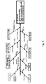
- Figure 1 shows the calibration process according to a first aspect of the invention.
- a number of composite samples are prepared at step 10. These composite samples are stored for a set time under set environmental conditions, as indicated by step 12. The samples are stored for a spread of different times and under different environmental conditions in order to provide a wide sample base for the calibration process. The range of conditions and number of samples required to give appropriate accuracy to the method is expanded upon with reference to figure 4 .
- Each of these samples is then examined by an infrared spectrometer 16, and also mechanically tested 18. Therefore, for each sample, an infrared spectrum is obtained, together with an assessment of one or more mechanical properties of the sample.
- the analysis of the samples includes classifying samples as either "acceptable” or “not acceptable” as indicated by step 22. In this case, “not acceptable” indicates a material is no longer suitable for use and should be repaired or replaced, and “acceptable” indicates that a material is suitable for use and does not require repair or replacement.
- the output may be in the form of different lights being illuminated on the testing device, or a screen associated with the testing device indicating the results, either as words and/or colours.
- the output may comprise a measure of the mechanical property of the sample, for example tensile strength, such that future infrared measurements of similar samples results in the display of the same mechanical reading.
- a skilled user may assess the value attributed to the measured mechanical property in order to decide whether or not the measured material requires any repair or replacement.
- the infrared spectrometer is programmed with the results data such that future analysis of measurement data may be performed automatically, as described further with respect to figure 2 .
- Figure 2 shows a method according to a second embodiment of the invention.
- An infrared spectrometer calibrated as described with reference to figure 1 , is used to take a measurement of a sample of composite material, as shown at step 26.
- the measurement spectra is then analysed by the spectrometer at step 28, where a comparison is made to the stored spectra results.
- the analysis of the spectra results in the determination of which category, acceptable or not acceptable, the composite material falls into, and the spectrometer outputs a user readable indication of the category at step 30.
- infrared spectrometers with the same specifications, for example the same make and model of infrared spectrometer, may be programmed with the appropriate calibration data without requiring the actual calibration process to be repeated.
- the indication of category 30 may be replaced by an indication of a value relating to a mechanical property of the measured material, such as tensile strength.
- FIG. 3 shows a spectrometer according to a third aspect of the invention.
- the spectrometer 32 is a handheld spectrometer comprising an infrared measurement device 34, a control unit 36, and a memory unit 38, and a display 40.
- the infrared measurement device is of common construction as would be understood by a skilled person.
- An example infrared measurement device is the hand-held IR spectrometer, 4100 ExoScan Series FTIR, available from Agilent Technologies, Santa Clara, USA.
- the memory unit 38 includes a database of correlations between infrared spectra and the measurement results obtained during the calibration process as described with reference to figure 1 .
- the infrared measurement device In order to take a measurement, a user holds the infrared measurement device up to a material and activates the device. The measurement results are analysed by the control unit 36 and compared to the database of results. Depending on the results of the analysis, the display 40 indicates what category the material falls into.
- Figure 4 shows a number of variables that may be input into a design of experiments model for determining how the samples are conditioned for the calibration process as described above.
- the variables include:
- the parameters tested may include the infrared spectra of the sample, the bearing strength of the sample, the plain compression strength of a sample, and the interlaminar shear strength of the sample.
- the choice of parameters is dependent on the skilled persons knowledge of composite materials.
- the parameters are entered into a design of experiments methodology in order to obtain a test matrix necessary to obtain a reliable set of calibration measurements.
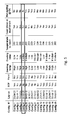
- the test matrix is shown in figure 5 .
- 15 configurations are determined sufficient to provide a suitable set of calibration measurements.
- the skilled person could use a number of computer software packages to run the design of experiments model, including JMP as available from SAS ( www.jmp.com - as available July 2014) and the open-source software, R-Project ( www.r-project.org - as available July 2014).
- Each configuration may include three samples being conditioned in the same way, to allow for each of the three mechanical tests to be carried out. The total number of samples required is then 45. This contrasts to testing each configuration with a number of samples, which will end up with a total number of samples in the hundreds or thousands.
- An example configuration highlighted in figure 5 is configuration 4.
- the sample has a 25/50/25 lay-up, no ECF, is not painted, experiences a high heating ramp, medium cooling ramp, reaches a maximum temperature of 200 degrees Celsius, does not have any dwell time and is not wet aged.
- the test matrix determines the how the samples are conditioned prior to the measurements being taken as described with reference to figure 1 .
- the infrared spectrometer may perform a measurement on a sample prior to the sample being conditioned.
- a reference spectrum may also be obtained before the raw material is painted, and also after painting but before conditioning to obtain a spectrum associated with the paint.
- a measurement may be performed on the painted sample to obtain a spectrum associated with the overheated paint, and after the sample has been sanded to remove the paint, to obtain the overheated sample spectrum without the influence of the paint residue.
- each sample may be notionally sub-divided into a number of "cells".
- the spectrometer may take a measurement of the spectra of each cell, and obtain an average reading across the whole sample.
Landscapes
- Physics & Mathematics (AREA)
- Spectroscopy & Molecular Physics (AREA)
- General Physics & Mathematics (AREA)
- Biochemistry (AREA)
- Chemical & Material Sciences (AREA)
- Analytical Chemistry (AREA)
- Life Sciences & Earth Sciences (AREA)
- General Health & Medical Sciences (AREA)
- Health & Medical Sciences (AREA)
- Immunology (AREA)
- Pathology (AREA)
- Engineering & Computer Science (AREA)
- Mathematical Physics (AREA)
- Theoretical Computer Science (AREA)
- Investigating Or Analysing Materials By Optical Means (AREA)
Abstract
Description
- The present disclosure relates to a method and apparatus for testing materials. More particularly, but not exclusively, this invention concerns a method and apparatus for testing materials using infrared spectrometry. The invention also concerns the calibration of an infrared spectrometer for use in testing materials using infrared spectrometry.
- Infrared spectrometry may be used to measure and/or monitor physical properties of composite materials. Composite materials are used extensively in the aerospace industry. The aerospace industry has exacting standards relating to materials quality. During the lifetime of an aircraft, various events may occur which can damage part of the aircraft. Example events include lightning strikes, holes being drilled in the aircraft during manufacturing or maintenance procedures, electrical arching, and laser treatment of materials during manufacturing or maintenance procedures. These events may result in the thermal degradation of composite materials making up the aircraft. Alternatively, during the manufacture or maintenance of an aircraft or aircraft component, a composite material may be overheated, for example during the curing of a composite material.
- European patent publication number
EP 2138829 discloses measuring the thermal effect of composite materials used in the aerospace industry using mid-range infrared spectroscopy. A hand-held infrared spectrometer is used to take measurements of a material, with the infrared spectra compared to a database of spectra to determine a physical property of that material. The hand-held infrared spectrometer is calibrated using a multivariate calibration process. Such a process can be time consuming. - The present invention seeks to mitigate the above-mentioned problems. Alternatively or additionally, the present invention seeks to provide an improved method of calibrating an infrared spectrometer.
- The present invention provides, according to a first aspect, a method of calibrating an infrared spectrometer for testing composites in the aerospace industry, comprising the steps of:
- selecting a plurality of variables which have the potential to influence the physical characteristics of a composite used in the aerospace industry;
- selecting a plurality of values for each variable;
- inputting the variables and values into a design of experiments model;
- thereby obtaining a sample test matrix.
- The invention may comprise a method of calibrating an infrared spectrometer for testing composites in the aerospace industry for thermal effects. Thermal effects may occur as a result of lightning strikes, holes being drilled in an aircraft during manufacturing or maintenance procedures, electrical arching, and laser treatment of materials during manufacturing or maintenance procedures. These events may result in the thermal degradation of composite materials making up an aircraft or aircraft component. Alternatively, during the manufacture or maintenance of an aircraft or aircraft component, a composite material may be overheated, for example during the curing of a composite material.
- Using the design of experiments method may reduce the testing required to obtain a results database for an infrared spectrometer to analyse results in comparison to. Accuracy of calibration may be increased, especially advantageous for safety and highly regulated products. The risk of not being able to characterise damage to a sample may be reduced. More than one resin type may be calibrated during the same calibration process. Multiple properties of the material may be tested without requiring a significant increase in testing costs. The method may provide a more accurate history of the damage done to a sample.
- The plurality of variables may include the configuration of the composite lay-up. For example, the lay-up may comprise a 50/40/10 directed lay up or a 25/50/25 quasi-isotropic lay-up.
- The plurality of variables may include whether or not the composite comprises an expanded copper foil (ECF).
- The plurality of variables may include whether or not the composite has been painted.
- The plurality of variables may include whether or not the composite has been wet aged.
- The plurality of variables may include the heating ramp in a composite curing process. The heating ramp may comprise a sample being thrown in a hot oven (high heating ramp) or a sample being heated at 2 degrees Celsius per minute (low heating ramp).
- The plurality of variables may include the maximum temperature reached by a sample. For example, the maximum temperature reached may be 200, 220, or 240 degrees Celsius.
- The plurality of variables may include whether or not the sample is allowed any dwell time. For example. the sample may be allowed dwell time of three hours, or no dwell time (less than one hour).
- The plurality of variables may include the cooling ramp of the sample, meaning how quickly the sample is cooled. The sample may be cooled at 7 degrees Celsius per minute (medium cooling ramp) or 2 degrees Celsius per minute (low cooling ramp).
- The method of calibration may comprise testing a plurality of composite samples according to the test matrix. The method may comprise the step of collating the infrared spectra detected by the infrared spectrometer with measured physical characteristics of a sample. The measured physical characteristics may include the bearing strength of a sample, the plain compression strength of a sample, and/or the interlaminar shear strength of a sample. The correlation of infrared spectra and measured physical characteristics may form a database of measurement results. The database of measurement results may be interrogated by the infrared spectrometer when taking a measurement of an aircraft or aircraft component, in order to provide a measurement of the physical characteristics of the aircraft or aircraft component.
- According to a second aspect of the invention, there is provided a method of testing an aircraft or aircraft component comprising composite material, the method comprising the steps of:
- taking a measurement of the composite material using an infrared spectrometer, thereby obtaining an infrared spectrum,
- comparing the infrared spectrum to a database of infrared spectra and correlated physical characteristics acquired according to the first aspect of the invention;
- thereby providing a value relating to a physical characteristic of the composite material.
- According to a third aspect of the invention, there is provided an infrared spectrometer for testing material characteristics of an aircraft or aircraft component, the infrared spectrometer calibrated as described in relation to the first aspect of the invention.
- It will of course be appreciated that features described in relation to one aspect of the present invention may be incorporated into other aspects of the present invention. For example, the method of the invention may incorporate any of the features described with reference to the apparatus of the invention and vice versa.
- Embodiments of the present invention will now be described by way of example only with reference to the accompanying schematic drawings of which:
-
Figure 1 shows a flow chart relating to a method according to a first embodiment of the invention; -
Figure 2 shows a flow chart relating to a method according to a second embodiment of the invention; -
Figure 3 shows a schematic representation of an infrared spectrometer according to a third embodiment of the invention; -
Figure 4 shows a plurality of variables which may be input into a design of experiments model according to a fourth embodiment of the invention; and -
Figure 5 shows a test matrix which may be produced by the design of experiments model according to a fifth embodiment of the invention. - The invention provides a method of calibrating an infrared spectrometer for taking infrared measurements of composite materials used in the aerospace industry. An example spectrometer which may be used is a handheld infrared spectrometer, such at the 4100 ExoScan Series FTIR, available from Agilent Technologies, Santa Clara, USA. Using a handheld infrared spectrometer allows an engineer to make an easy assessment of a material onsite. The spectrometer may provide a clear indication of whether a composite material is suitable for use, should be repaired, or replaced, depending on how the material is being used, or would be used. The spectrometer may allow a composite material to be tested after exposure to potential thermal damage.
-
Figure 1 shows the calibration process according to a first aspect of the invention. Firstly, a number of composite samples are prepared atstep 10. These composite samples are stored for a set time under set environmental conditions, as indicated bystep 12. The samples are stored for a spread of different times and under different environmental conditions in order to provide a wide sample base for the calibration process. The range of conditions and number of samples required to give appropriate accuracy to the method is expanded upon with reference tofigure 4 . This results in a collection of variously conditionedcomposite samples 14. Each of these samples is then examined by aninfrared spectrometer 16, and also mechanically tested 18. Therefore, for each sample, an infrared spectrum is obtained, together with an assessment of one or more mechanical properties of the sample. These measurement results are stored in a database, and statistical analysis is performed to correlate infrared spectra with the physical properties of the sample, as shown instep 20. The analysis of the samples includes classifying samples as either "acceptable" or "not acceptable" as indicated bystep 22. In this case, "not acceptable" indicates a material is no longer suitable for use and should be repaired or replaced, and "acceptable" indicates that a material is suitable for use and does not require repair or replacement. The output may be in the form of different lights being illuminated on the testing device, or a screen associated with the testing device indicating the results, either as words and/or colours. - In an alternative embodiment, the output may comprise a measure of the mechanical property of the sample, for example tensile strength, such that future infrared measurements of similar samples results in the display of the same mechanical reading. A skilled user may assess the value attributed to the measured mechanical property in order to decide whether or not the measured material requires any repair or replacement.
- As the
final step 24 in the calibration process, the infrared spectrometer is programmed with the results data such that future analysis of measurement data may be performed automatically, as described further with respect tofigure 2 . -
Figure 2 shows a method according to a second embodiment of the invention. An infrared spectrometer, calibrated as described with reference tofigure 1 , is used to take a measurement of a sample of composite material, as shown atstep 26. The measurement spectra is then analysed by the spectrometer atstep 28, where a comparison is made to the stored spectra results. The analysis of the spectra results in the determination of which category, acceptable or not acceptable, the composite material falls into, and the spectrometer outputs a user readable indication of the category atstep 30. Once an infrared spectrometer has been calibrated correctly, infrared spectrometers with the same specifications, for example the same make and model of infrared spectrometer, may be programmed with the appropriate calibration data without requiring the actual calibration process to be repeated. In an alternative embodiment, the indication ofcategory 30 may be replaced by an indication of a value relating to a mechanical property of the measured material, such as tensile strength. -
Figure 3 shows a spectrometer according to a third aspect of the invention. Thespectrometer 32 is a handheld spectrometer comprising aninfrared measurement device 34, acontrol unit 36, and amemory unit 38, and adisplay 40. The infrared measurement device is of common construction as would be understood by a skilled person. An example infrared measurement device is the hand-held IR spectrometer, 4100 ExoScan Series FTIR, available from Agilent Technologies, Santa Clara, USA. Thememory unit 38 includes a database of correlations between infrared spectra and the measurement results obtained during the calibration process as described with reference tofigure 1 . In order to take a measurement, a user holds the infrared measurement device up to a material and activates the device. The measurement results are analysed by thecontrol unit 36 and compared to the database of results. Depending on the results of the analysis, thedisplay 40 indicates what category the material falls into. -
Figure 4 shows a number of variables that may be input into a design of experiments model for determining how the samples are conditioned for the calibration process as described above. The variables include: - Lay-up - for example the sample lay-up may be 50/40/10 directed, or 25/50/25 quasi-isotropic;
- Expanded Copper Foil (ECF) - whether the sample includes or does not include expanded copper foil;
- Paint - whether the sample has been or has not been painted;
- Wet aging - whether or not the sample has been wet aged;
- Heating ramp - how quickly the sample is heated, for example being thrown in an oven (high) or 2 degrees Celsius per minute (low);
- Temperature to reach - the maximum temperature reached, for example 200, 220, or 240 degrees Celsius;
- Dwell time - whether the sample is allowed dwell time (3 hours) or no dwell time (1 hour);
- Cooling ramp - how quickly the sample is cooled, for example, 7 degrees Celsius per minute (medium) or 2 degrees Celsius per minute (low).
- The parameters tested may include the infrared spectra of the sample, the bearing strength of the sample, the plain compression strength of a sample, and the interlaminar shear strength of the sample.
- The choice of parameters is dependent on the skilled persons knowledge of composite materials. The parameters are entered into a design of experiments methodology in order to obtain a test matrix necessary to obtain a reliable set of calibration measurements. The test matrix is shown in
figure 5 . As can be seen, 15 configurations are determined sufficient to provide a suitable set of calibration measurements. The skilled person could use a number of computer software packages to run the design of experiments model, including JMP as available from SAS (www.jmp.com - as available July 2014) and the open-source software, R-Project (www.r-project.org - as available July 2014). - This contrasts to testing each possible combination of variables, which with eight variables chosen and two levels per variable (ignoring for simplicity the temperature to reach variable having three levels) would result in 256 configurations being tested. This presents a significant saving in time and cost of calibrating the infrared spectrometer. Each configuration may include three samples being conditioned in the same way, to allow for each of the three mechanical tests to be carried out. The total number of samples required is then 45. This contrasts to testing each configuration with a number of samples, which will end up with a total number of samples in the hundreds or thousands.
- An example configuration highlighted in
figure 5 is configuration 4. In this configuration, the sample has a 25/50/25 lay-up, no ECF, is not painted, experiences a high heating ramp, medium cooling ramp, reaches a maximum temperature of 200 degrees Celsius, does not have any dwell time and is not wet aged. - The test matrix determines the how the samples are conditioned prior to the measurements being taken as described with reference to
figure 1 . In order to provide a reference spectrum, the infrared spectrometer may perform a measurement on a sample prior to the sample being conditioned. For painted samples, a reference spectrum may also be obtained before the raw material is painted, and also after painting but before conditioning to obtain a spectrum associated with the paint. After conditioning, a measurement may be performed on the painted sample to obtain a spectrum associated with the overheated paint, and after the sample has been sanded to remove the paint, to obtain the overheated sample spectrum without the influence of the paint residue. - In order to provide a representative measurement of each of the samples of material, each sample may be notionally sub-divided into a number of "cells". The spectrometer may take a measurement of the spectra of each cell, and obtain an average reading across the whole sample.
- Whilst the present invention has been described and illustrated with reference to particular embodiments, it will be appreciated by those of ordinary skill in the art that the invention lends itself to many different variations not specifically illustrated herein. Where in the foregoing description, integers or elements are mentioned which have known, obvious or foreseeable equivalents, then such equivalents are herein incorporated as if individually set forth. Reference should be made to the claims for determining the true scope of the present invention, which should be construed so as to encompass any such equivalents. It will also be appreciated by the reader that integers or features of the invention that are described as preferable, advantageous, convenient or the like are optional and do not limit the scope of the independent claims. Moreover, it is to be understood that such optional integers or features, whilst of possible benefit in some embodiments of the invention, may not be desirable, and may therefore be absent, in other embodiments.
Claims (5)
- A method of testing an aircraft or aircraft component comprising composite material, the method comprising the steps of:calibrating an infrared spectrometer by selecting a plurality of variables which have the potential to influence the physical characteristics of a composite used in the aerospace industry, the calibration comprising:selecting a plurality of values for each variable;inputting the variables and values into a design of experiments model, thereby obtaining a sample test matrix;testing a plurality of composite samples according to the test matrix, thereby obtaining a number of infrared spectra;testing a physical characteristic of the composite samples;collating the infrared spectra detected by the infrared spectrometer with the measured physical characteristic of a sample;wherein the correlation of infrared spectra and measured physical characteristics forms a database of measurement results; the method of testing further comprising:taking a measurement of the aircraft or aircraft component comprising composite material using an infrared spectrometer, thereby obtaining an infrared spectrum,comparing the infrared spectrum to the database of infrared spectra and correlated physical characteristics;thereby providing a value relating to a measurement of a physical characteristic of the composite material.
- A method as claimed in claim 1, comprising calibrating an infrared spectrometer for testing composites in the aerospace industry for thermal effects.
- A method as claimed in claim 1 or claim 2, wherein the plurality of variables includes at least one of:the configuration of the composite lay up;whether or not the composite comprises an expanded copper foil (ECF);whether or not the composite has been painted;whether or not the composite has been wet aged;the heating ramp in a composite curing process;the maximum temperature reached in a composite curing process;whether or not the composite is allowed any dwell time; orthe cooling ramp of the composite.
- A method as claimed in any of claims 1 to 3, wherein the measured physical characteristics include at least one of:the bearing strength of a sample;the plain compression strength of a sample, orthe interlaminar shear strength of a sample.
- An infrared spectrometer for testing material characteristics of an aircraft or aircraft component, the infrared spectrometer calibrated as claimed in any of claims 1 to 4.
Applications Claiming Priority (1)
| Application Number | Priority Date | Filing Date | Title |
|---|---|---|---|
| GB1413083.5A GB2528488A (en) | 2014-07-23 | 2014-07-23 | Method and apparatus for testing materials |
Publications (1)
| Publication Number | Publication Date |
|---|---|
| EP2977747A1 true EP2977747A1 (en) | 2016-01-27 |
Family
ID=51495024
Family Applications (1)
| Application Number | Title | Priority Date | Filing Date |
|---|---|---|---|
| EP15176715.9A Withdrawn EP2977747A1 (en) | 2014-07-23 | 2015-07-14 | Method and apparatus for testing materials |
Country Status (4)
| Country | Link |
|---|---|
| US (1) | US9523606B2 (en) |
| EP (1) | EP2977747A1 (en) |
| CN (1) | CN105300915A (en) |
| GB (1) | GB2528488A (en) |
Cited By (1)
| Publication number | Priority date | Publication date | Assignee | Title |
|---|---|---|---|---|
| EP3531109A1 (en) * | 2018-02-22 | 2019-08-28 | The Boeing Company | Active real-time characterization system providing spectrally broadband characterization |
Families Citing this family (1)
| Publication number | Priority date | Publication date | Assignee | Title |
|---|---|---|---|---|
| US10816513B2 (en) * | 2016-08-10 | 2020-10-27 | University Of South Carolina | Wireless damage assessment during manufacturing |
Citations (4)
| Publication number | Priority date | Publication date | Assignee | Title |
|---|---|---|---|---|
| EP2138829A1 (en) * | 2008-08-14 | 2009-12-30 | The Boeing Company | Thermal effect measurement with mid-infrared spectroscopy |
| US20090321648A1 (en) * | 2008-06-28 | 2009-12-31 | The Boeing Company | Sample Preparation and Methods for Portable IR Spectroscopy Measurements of UV and Thermal Effect |
| US20090323757A1 (en) * | 2008-06-28 | 2009-12-31 | The Boeing Company | Method for Fabricating Thermal Effect Standards |
| US20110001047A1 (en) * | 2008-08-14 | 2011-01-06 | The Boeing Company | Method of Predicting Thermal or Chemical Effect In A Coated Or Painted Composite Material |
Family Cites Families (22)
| Publication number | Priority date | Publication date | Assignee | Title |
|---|---|---|---|---|
| US5204532A (en) | 1989-01-19 | 1993-04-20 | Futrex, Inc. | Method for providing general calibration for near infrared instruments for measurement of blood glucose |
| US5457319A (en) | 1993-06-02 | 1995-10-10 | Alliedsignal Inc. | Process for measurement of the degree of cure and percent resin of glass-fiber reinforced epoxy resin prepreg |
| US5473161A (en) | 1994-06-21 | 1995-12-05 | The Coca-Cola Company | Method for testing carbonation loss from beverage bottles using IR spectroscopy |
| US5712165A (en) | 1994-08-22 | 1998-01-27 | Beth Israel Hospital Administration | Method and apparatus for detecting hydrocarbon oxidation |
| EP1070956A1 (en) | 1999-07-23 | 2001-01-24 | Datex-Ohmeda, Inc. | Method and apparatus for monitoring maintenance of calibration condition in respiratory gas spectrometer |
| EP1281064B1 (en) | 2000-05-10 | 2008-07-16 | DSM IP Assets B.V. | Process for identifying objects using an optical spectrometer and a transport system |
| US6749565B2 (en) | 2000-07-08 | 2004-06-15 | Victor Chudner | Method for blood infrared spectroscopy diagnosing of inner organs pathology |
| KR100390567B1 (en) | 2000-12-30 | 2003-07-07 | 주식회사 동진쎄미켐 | method of controlling photoresist stripping process and method of regenerating photoresist stripping composition using near infrared spectrometer |
| US6876931B2 (en) * | 2001-08-03 | 2005-04-05 | Sensys Medical Inc. | Automatic process for sample selection during multivariate calibration |
| CA2503610C (en) | 2002-11-06 | 2011-08-02 | Her Majesty The Queen In Right Of Canada As Represented By The Minister Of Natural Resources Canada | Nir spectroscopy method for analyzing chemical process components |
| US8203700B2 (en) | 2007-05-21 | 2012-06-19 | Ahura Scientific Inc. | Supporting remote analysis |
| CN102046070A (en) | 2008-03-28 | 2011-05-04 | 俄亥俄州立大学 | Rapid diagnosis of a disease condition using infrared spectroscopy |
| US8835854B2 (en) | 2008-04-14 | 2014-09-16 | The Boeing Company | Method and device for IR spectroscopy measurements with fiber optic needle probe |
| US7956327B2 (en) | 2008-09-22 | 2011-06-07 | The Boeing Company | Method for determining degree of aging of a polymer resin material |
| JP5233666B2 (en) | 2008-12-26 | 2013-07-10 | 富士通株式会社 | Life expectancy calculation device, portable terminal device, life expectancy calculation method, and life expectancy calculation program |
| JP5102793B2 (en) | 2009-02-23 | 2012-12-19 | パナソニック株式会社 | Prepreg curing measurement method |
| US20110085030A1 (en) | 2009-10-07 | 2011-04-14 | John Zink Company, Llc | Image sensing system, software, apparatus and method for controlling combustion equipment |
| US8319182B1 (en) | 2010-07-27 | 2012-11-27 | The Boeing Company | Methods and systems for using IR spectroscopy to quantify degradation of wiring insulation |
| US8330109B2 (en) * | 2010-09-02 | 2012-12-11 | The Boeing Company | Method for determining contamination of material using Mid-IR spectroscopy |
| US20120078532A1 (en) | 2010-09-24 | 2012-03-29 | David Edward Forsyth | Non-dispersive infrared sensor measurement system and method |
| AU2011314214A1 (en) | 2010-09-29 | 2013-05-23 | Aerobotics, Inc. | Novel systems and methods for non-destructive inspection of airplanes |
| EP2743677A1 (en) | 2012-12-14 | 2014-06-18 | Nxp B.V. | IR COx sensor and integrated circuit comprising the same |
-
2014
- 2014-07-23 GB GB1413083.5A patent/GB2528488A/en not_active Withdrawn
-
2015
- 2015-07-14 EP EP15176715.9A patent/EP2977747A1/en not_active Withdrawn
- 2015-07-22 CN CN201510434569.3A patent/CN105300915A/en active Pending
- 2015-07-23 US US14/807,273 patent/US9523606B2/en not_active Expired - Fee Related
Patent Citations (4)
| Publication number | Priority date | Publication date | Assignee | Title |
|---|---|---|---|---|
| US20090321648A1 (en) * | 2008-06-28 | 2009-12-31 | The Boeing Company | Sample Preparation and Methods for Portable IR Spectroscopy Measurements of UV and Thermal Effect |
| US20090323757A1 (en) * | 2008-06-28 | 2009-12-31 | The Boeing Company | Method for Fabricating Thermal Effect Standards |
| EP2138829A1 (en) * | 2008-08-14 | 2009-12-30 | The Boeing Company | Thermal effect measurement with mid-infrared spectroscopy |
| US20110001047A1 (en) * | 2008-08-14 | 2011-01-06 | The Boeing Company | Method of Predicting Thermal or Chemical Effect In A Coated Or Painted Composite Material |
Non-Patent Citations (3)
| Title |
|---|
| HOWIE T ET AL: "The detection of incipient thermal damage of CFRP using FTIR", SAMPE TECH SEATTLE 2014 CONFERENCE 20140602 TO 20140605 WASHINGTON STATE CONVENTION CENTER 800 CONVENTION PLACE SEATTLE WA 98101-2350, 2 June 2014 (2014-06-02) - 5 June 2014 (2014-06-05), USA, pages 12pp, XP009187666 * |
| I. H. DARA ET AL: "Heat-damage assessment of carbon-fiber-reinforced polymer composites by diffuse reflectance infrared spectroscopy", JOURNAL OF APPLIED POLYMER SCIENCE, vol. 96, no. 4, 10 March 2005 (2005-03-10), pages 1222 - 1230, XP055118210, ISSN: 0021-8995, DOI: 10.1002/app.21500 * |
| WOLFRUM J ET AL: "Rapid evaluation of long-term thermal degradation of carbon fibre epoxy composites", COMPOSITES SCIENCE AND TECHNOLOGY, ELSEVIER, UK, vol. 69, no. 3-4, March 2009 (2009-03-01), pages 523 - 530, XP025911897, ISSN: 0266-3538, [retrieved on 20081203], DOI: 10.1016/J.COMPSCITECH.2008.11.018 * |
Cited By (2)
| Publication number | Priority date | Publication date | Assignee | Title |
|---|---|---|---|---|
| EP3531109A1 (en) * | 2018-02-22 | 2019-08-28 | The Boeing Company | Active real-time characterization system providing spectrally broadband characterization |
| US10712265B2 (en) | 2018-02-22 | 2020-07-14 | The Boeing Company | Active real-time characterization system providing spectrally broadband characterization |
Also Published As
| Publication number | Publication date |
|---|---|
| US20160025566A1 (en) | 2016-01-28 |
| GB201413083D0 (en) | 2014-09-03 |
| US9523606B2 (en) | 2016-12-20 |
| CN105300915A (en) | 2016-02-03 |
| GB2528488A (en) | 2016-01-27 |
Similar Documents
| Publication | Publication Date | Title |
|---|---|---|
| EP2138829B1 (en) | Thermal effect measurement with mid-infrared spectroscopy | |
| US20160025565A1 (en) | Apparatus and method for testing materials | |
| EP2138830B1 (en) | IR spectroscopic method for determining UV degradation of a polymer composite material surface in a portion of an aircraft | |
| EP2366101B1 (en) | Determination of bond strength of a resin-fibre composite material based on moisture content measured using infared spectroscopy | |
| US8536529B2 (en) | Non-contact surface chemistry measurement apparatus and method | |
| US8436311B2 (en) | Method of predicting thermal or chemical effect in a coated or painted composite material | |
| Dekker et al. | Total appearance differences for metallic and pearlescent materials: contributions from color and texture | |
| US9523606B2 (en) | Method and apparatus for testing materials | |
| US20170241924A1 (en) | Method of characterizing the thermal ageing of composite materials, in particular composite materials having an organic matrix | |
| US8083399B2 (en) | Method for fabricating thermal effect standards | |
| US8519337B2 (en) | Thermal effect measurement with near-infrared spectroscopy | |
| CN110662886B (en) | Method for the non-destructive testing of a housing by colorimetry | |
| Stoček et al. | Heat build-up characterization under realistic load | |
| Higgins | Non-Destructive Evaluation of Composite Thermal Damage with Agilent’s New Handheld 4300 FTIR | |
| CN110662887B (en) | Method for inspecting housings by colorimetry | |
| Eibl | Quantification of a thermal pre‐load on polymer matrix composites by the degradation and colour change of polyurethane top coats: Quantifizierung der thermischen Schädigung von faserverstärkten Kunststoffen anhand des Bindemittels und der Farbveränderung von Polyurethandecklacken | |
| US10458906B2 (en) | Method for the non-destructive testing of a casing | |
| Yifei et al. | Standard Processes for Calculating Uncertainty for Metallic Material Rotating Bar Bending Fatigue Properties | |
| Rusk et al. | High-Frequency Axial Fatigue Test Procedures for Spectrum Loading | |
| Engelhard et al. | Current best practice for traceability in testing laboratories, when certified reference materials are unavailable | |
| Makowski et al. | Validation as a confirmation of the planned process of obtaining results | |
| Viveiros et al. | GR&R: Understanding Sources of Error in Mechanical Testing Results | |
| Ulmanu et al. | An Experimental Study on Fatigue Properties Determination by Using Quantitative Infrared Thermography | |
| Silva et al. | Application of a Methodology for Measuring Aerospace Parts by Ultrasonic Considering the Measurement Uncertainty through Analytical and Monte Carlo Simulation Method | |
| Zuluaga-Ramírez et al. | www. mdpi. com/journal/sensors |
Legal Events
| Date | Code | Title | Description |
|---|---|---|---|
| PUAI | Public reference made under article 153(3) epc to a published international application that has entered the european phase |
Free format text: ORIGINAL CODE: 0009012 |
|
| AK | Designated contracting states |
Kind code of ref document: A1 Designated state(s): AL AT BE BG CH CY CZ DE DK EE ES FI FR GB GR HR HU IE IS IT LI LT LU LV MC MK MT NL NO PL PT RO RS SE SI SK SM TR |
|
| AX | Request for extension of the european patent |
Extension state: BA ME |
|
| 17P | Request for examination filed |
Effective date: 20160715 |
|
| RBV | Designated contracting states (corrected) |
Designated state(s): AL AT BE BG CH CY CZ DE DK EE ES FI FR GB GR HR HU IE IS IT LI LT LU LV MC MK MT NL NO PL PT RO RS SE SI SK SM TR |
|
| STAA | Information on the status of an ep patent application or granted ep patent |
Free format text: STATUS: REQUEST FOR EXAMINATION WAS MADE |
|
| STAA | Information on the status of an ep patent application or granted ep patent |
Free format text: STATUS: THE APPLICATION IS DEEMED TO BE WITHDRAWN |
|
| 18D | Application deemed to be withdrawn |
Effective date: 20180201 |