EP2977737A2 - Blunt impact indicator methods - Google Patents
Blunt impact indicator methods Download PDFInfo
- Publication number
- EP2977737A2 EP2977737A2 EP15174164.2A EP15174164A EP2977737A2 EP 2977737 A2 EP2977737 A2 EP 2977737A2 EP 15174164 A EP15174164 A EP 15174164A EP 2977737 A2 EP2977737 A2 EP 2977737A2
- Authority
- EP
- European Patent Office
- Prior art keywords
- substrate
- shells
- electrically conductive
- multiplicity
- conductive fluid
- Prior art date
- Legal status (The legal status is an assumption and is not a legal conclusion. Google has not performed a legal analysis and makes no representation as to the accuracy of the status listed.)
- Granted
Links
- 238000000034 method Methods 0.000 title claims abstract description 52
- 239000000758 substrate Substances 0.000 claims abstract description 122
- 239000012530 fluid Substances 0.000 claims abstract description 110
- 239000004005 microsphere Substances 0.000 claims abstract description 97
- 230000008859 change Effects 0.000 claims abstract description 29
- 230000004044 response Effects 0.000 claims abstract description 17
- 238000012544 monitoring process Methods 0.000 claims abstract description 15
- 239000004020 conductor Substances 0.000 claims description 107
- WYTGDNHDOZPMIW-RCBQFDQVSA-N alstonine Natural products C1=CC2=C3C=CC=CC3=NC2=C2N1C[C@H]1[C@H](C)OC=C(C(=O)OC)[C@H]1C2 WYTGDNHDOZPMIW-RCBQFDQVSA-N 0.000 claims description 24
- 238000001931 thermography Methods 0.000 claims description 18
- 230000001939 inductive effect Effects 0.000 claims description 9
- 239000000463 material Substances 0.000 claims description 9
- 239000003989 dielectric material Substances 0.000 claims description 5
- 238000007689 inspection Methods 0.000 abstract description 10
- 239000011248 coating agent Substances 0.000 abstract description 9
- 238000000576 coating method Methods 0.000 abstract description 9
- 238000001514 detection method Methods 0.000 abstract description 6
- 239000010410 layer Substances 0.000 description 29
- 238000010586 diagram Methods 0.000 description 23
- 239000000523 sample Substances 0.000 description 20
- 230000006698 induction Effects 0.000 description 14
- 238000010438 heat treatment Methods 0.000 description 7
- 238000004519 manufacturing process Methods 0.000 description 7
- 230000005672 electromagnetic field Effects 0.000 description 6
- 230000006870 function Effects 0.000 description 6
- 239000002344 surface layer Substances 0.000 description 6
- 239000000853 adhesive Substances 0.000 description 5
- 230000001070 adhesive effect Effects 0.000 description 5
- 230000001066 destructive effect Effects 0.000 description 5
- 230000000007 visual effect Effects 0.000 description 5
- 230000006399 behavior Effects 0.000 description 4
- 239000002131 composite material Substances 0.000 description 4
- 230000005284 excitation Effects 0.000 description 4
- 238000012423 maintenance Methods 0.000 description 4
- 230000008569 process Effects 0.000 description 4
- 238000012545 processing Methods 0.000 description 4
- 238000004891 communication Methods 0.000 description 3
- 239000004033 plastic Substances 0.000 description 3
- OKTJSMMVPCPJKN-UHFFFAOYSA-N Carbon Chemical compound [C] OKTJSMMVPCPJKN-UHFFFAOYSA-N 0.000 description 2
- 239000012790 adhesive layer Substances 0.000 description 2
- 239000000975 dye Substances 0.000 description 2
- 230000005670 electromagnetic radiation Effects 0.000 description 2
- 230000007613 environmental effect Effects 0.000 description 2
- 238000011156 evaluation Methods 0.000 description 2
- 229910002804 graphite Inorganic materials 0.000 description 2
- 239000010439 graphite Substances 0.000 description 2
- 239000007788 liquid Substances 0.000 description 2
- 230000004048 modification Effects 0.000 description 2
- 238000012986 modification Methods 0.000 description 2
- 239000007921 spray Substances 0.000 description 2
- 239000003981 vehicle Substances 0.000 description 2
- 108010053481 Antifreeze Proteins Proteins 0.000 description 1
- 230000003213 activating effect Effects 0.000 description 1
- 230000004913 activation Effects 0.000 description 1
- 239000000654 additive Substances 0.000 description 1
- 230000002528 anti-freeze Effects 0.000 description 1
- 230000008901 benefit Effects 0.000 description 1
- 239000003990 capacitor Substances 0.000 description 1
- 239000000919 ceramic Substances 0.000 description 1
- 239000003086 colorant Substances 0.000 description 1
- 230000001419 dependent effect Effects 0.000 description 1
- 238000013461 design Methods 0.000 description 1
- 239000012636 effector Substances 0.000 description 1
- 230000005684 electric field Effects 0.000 description 1
- 238000005516 engineering process Methods 0.000 description 1
- 239000011521 glass Substances 0.000 description 1
- 238000003384 imaging method Methods 0.000 description 1
- 230000006872 improvement Effects 0.000 description 1
- 230000010354 integration Effects 0.000 description 1
- 239000011159 matrix material Substances 0.000 description 1
- 238000005259 measurement Methods 0.000 description 1
- 238000000691 measurement method Methods 0.000 description 1
- 230000008520 organization Effects 0.000 description 1
- 238000002360 preparation method Methods 0.000 description 1
- 239000011241 protective layer Substances 0.000 description 1
- 230000009467 reduction Effects 0.000 description 1
- 238000009419 refurbishment Methods 0.000 description 1
- 230000008439 repair process Effects 0.000 description 1
- 239000002904 solvent Substances 0.000 description 1
- 238000003860 storage Methods 0.000 description 1
- 239000004094 surface-active agent Substances 0.000 description 1
- 239000000725 suspension Substances 0.000 description 1
- 230000001360 synchronised effect Effects 0.000 description 1
- XLYOFNOQVPJJNP-UHFFFAOYSA-N water Substances O XLYOFNOQVPJJNP-UHFFFAOYSA-N 0.000 description 1
Images


Classifications
-
- G—PHYSICS
- G01—MEASURING; TESTING
- G01L—MEASURING FORCE, STRESS, TORQUE, WORK, MECHANICAL POWER, MECHANICAL EFFICIENCY, OR FLUID PRESSURE
- G01L1/00—Measuring force or stress, in general
- G01L1/24—Measuring force or stress, in general by measuring variations of optical properties of material when it is stressed, e.g. by photoelastic stress analysis using infrared, visible light, ultraviolet
- G01L1/247—Measuring force or stress, in general by measuring variations of optical properties of material when it is stressed, e.g. by photoelastic stress analysis using infrared, visible light, ultraviolet using distributed sensing elements, e.g. microcapsules
-
- B—PERFORMING OPERATIONS; TRANSPORTING
- B64—AIRCRAFT; AVIATION; COSMONAUTICS
- B64D—EQUIPMENT FOR FITTING IN OR TO AIRCRAFT; FLIGHT SUITS; PARACHUTES; ARRANGEMENTS OR MOUNTING OF POWER PLANTS OR PROPULSION TRANSMISSIONS IN AIRCRAFT
- B64D45/00—Aircraft indicators or protectors not otherwise provided for
-
- B—PERFORMING OPERATIONS; TRANSPORTING
- B64—AIRCRAFT; AVIATION; COSMONAUTICS
- B64F—GROUND OR AIRCRAFT-CARRIER-DECK INSTALLATIONS SPECIALLY ADAPTED FOR USE IN CONNECTION WITH AIRCRAFT; DESIGNING, MANUFACTURING, ASSEMBLING, CLEANING, MAINTAINING OR REPAIRING AIRCRAFT, NOT OTHERWISE PROVIDED FOR; HANDLING, TRANSPORTING, TESTING OR INSPECTING AIRCRAFT COMPONENTS, NOT OTHERWISE PROVIDED FOR
- B64F5/00—Designing, manufacturing, assembling, cleaning, maintaining or repairing aircraft, not otherwise provided for; Handling, transporting, testing or inspecting aircraft components, not otherwise provided for
- B64F5/60—Testing or inspecting aircraft components or systems
-
- G—PHYSICS
- G01—MEASURING; TESTING
- G01L—MEASURING FORCE, STRESS, TORQUE, WORK, MECHANICAL POWER, MECHANICAL EFFICIENCY, OR FLUID PRESSURE
- G01L5/00—Apparatus for, or methods of, measuring force, work, mechanical power, or torque, specially adapted for specific purposes
- G01L5/0052—Apparatus for, or methods of, measuring force, work, mechanical power, or torque, specially adapted for specific purposes measuring forces due to impact
-
- G—PHYSICS
- G01—MEASURING; TESTING
- G01L—MEASURING FORCE, STRESS, TORQUE, WORK, MECHANICAL POWER, MECHANICAL EFFICIENCY, OR FLUID PRESSURE
- G01L5/00—Apparatus for, or methods of, measuring force, work, mechanical power, or torque, specially adapted for specific purposes
- G01L5/14—Apparatus for, or methods of, measuring force, work, mechanical power, or torque, specially adapted for specific purposes for measuring the force of explosions; for measuring the energy of projectiles
-
- G—PHYSICS
- G01—MEASURING; TESTING
- G01M—TESTING STATIC OR DYNAMIC BALANCE OF MACHINES OR STRUCTURES; TESTING OF STRUCTURES OR APPARATUS, NOT OTHERWISE PROVIDED FOR
- G01M5/00—Investigating the elasticity of structures, e.g. deflection of bridges or air-craft wings
- G01M5/0083—Investigating the elasticity of structures, e.g. deflection of bridges or air-craft wings by measuring variation of impedance, e.g. resistance, capacitance, induction
-
- G—PHYSICS
- G01—MEASURING; TESTING
- G01M—TESTING STATIC OR DYNAMIC BALANCE OF MACHINES OR STRUCTURES; TESTING OF STRUCTURES OR APPARATUS, NOT OTHERWISE PROVIDED FOR
- G01M5/00—Investigating the elasticity of structures, e.g. deflection of bridges or air-craft wings
- G01M5/0091—Investigating the elasticity of structures, e.g. deflection of bridges or air-craft wings by using electromagnetic excitation or detection
-
- G—PHYSICS
- G01—MEASURING; TESTING
- G01M—TESTING STATIC OR DYNAMIC BALANCE OF MACHINES OR STRUCTURES; TESTING OF STRUCTURES OR APPARATUS, NOT OTHERWISE PROVIDED FOR
- G01M9/00—Aerodynamic testing; Arrangements in or on wind tunnels
-
- G—PHYSICS
- G01—MEASURING; TESTING
- G01N—INVESTIGATING OR ANALYSING MATERIALS BY DETERMINING THEIR CHEMICAL OR PHYSICAL PROPERTIES
- G01N27/00—Investigating or analysing materials by the use of electric, electrochemical, or magnetic means
- G01N27/72—Investigating or analysing materials by the use of electric, electrochemical, or magnetic means by investigating magnetic variables
- G01N27/82—Investigating or analysing materials by the use of electric, electrochemical, or magnetic means by investigating magnetic variables for investigating the presence of flaws
- G01N27/90—Investigating or analysing materials by the use of electric, electrochemical, or magnetic means by investigating magnetic variables for investigating the presence of flaws using eddy currents
-
- G—PHYSICS
- G01—MEASURING; TESTING
- G01N—INVESTIGATING OR ANALYSING MATERIALS BY DETERMINING THEIR CHEMICAL OR PHYSICAL PROPERTIES
- G01N3/00—Investigating strength properties of solid materials by application of mechanical stress
-
- G—PHYSICS
- G01—MEASURING; TESTING
- G01P—MEASURING LINEAR OR ANGULAR SPEED, ACCELERATION, DECELERATION, OR SHOCK; INDICATING PRESENCE, ABSENCE, OR DIRECTION, OF MOVEMENT
- G01P15/00—Measuring acceleration; Measuring deceleration; Measuring shock, i.e. sudden change of acceleration
- G01P15/02—Measuring acceleration; Measuring deceleration; Measuring shock, i.e. sudden change of acceleration by making use of inertia forces using solid seismic masses
- G01P15/04—Measuring acceleration; Measuring deceleration; Measuring shock, i.e. sudden change of acceleration by making use of inertia forces using solid seismic masses for indicating maximum value
- G01P15/06—Measuring acceleration; Measuring deceleration; Measuring shock, i.e. sudden change of acceleration by making use of inertia forces using solid seismic masses for indicating maximum value using members subjected to a permanent deformation
-
- H—ELECTRICITY
- H01—ELECTRIC ELEMENTS
- H01H—ELECTRIC SWITCHES; RELAYS; SELECTORS; EMERGENCY PROTECTIVE DEVICES
- H01H29/00—Switches having at least one liquid contact
- H01H29/002—Inertia switches
-
- H—ELECTRICITY
- H01—ELECTRIC ELEMENTS
- H01H—ELECTRIC SWITCHES; RELAYS; SELECTORS; EMERGENCY PROTECTIVE DEVICES
- H01H35/00—Switches operated by change of a physical condition
- H01H35/14—Switches operated by change of acceleration, e.g. by shock or vibration, inertia switch
- H01H35/146—Switches operated by change of acceleration, e.g. by shock or vibration, inertia switch operated by plastic deformation or rupture of structurally associated elements
Definitions
- This disclosure generally relates to systems and methods for monitoring or indicating high-energy impacts on a structure. More particularly, this disclosure relates to systems and methods for measuring the magnitude and location of a high-energy impact event.
- NDE non-destructive evaluation
- an aircraft may be vulnerable to high-energy blunt impacts from support vehicles and ground support equipment such as cargo belt loaders, luggage carts, aircraft refuelers, catering vehicles, ground power units, airport buses and passenger boarding stairs.
- the customary first maintenance procedure is to perform a non-destructive evaluation of the impacted area sufficient to determine an appropriate disposition, e.g., repair the damage to the aircraft.
- a multiplicity of microspheres may be adhered to or embedded in a coating applied on a surface of a substrate (e.g., a tape or an appliqué), which substrate in turn can be adhered to a surface of a structure to be monitored.
- the microspheres are designed to rupture at one or more specified pressure thresholds.
- the microspheres are filled with electrically conductive fluid which, if released from ruptured microsphere, changes the electromagnetic state of the substrate. In response to the detection of a sufficiently large change in the electromagnetic state of the substrate, a blunt impact indication is generated. The impact site may then undergo non-destructive inspection.
- a blunt impact indicator device comprising: a substrate comprising first and second surfaces; and a multiplicity of rupturable shells disposed in proximity to said first surface of said substrate, the shells having an electrically conductive fluid disposed in an internal volume of the shells.
- the shells can be hollow microspheres made of dielectric material.
- the substrate may be in the form of a tape or an appliqué.
- the blunt impact indicator device further comprises: first and second electrical conductors; and a voltage supply connected to the first and second electrical conductors, wherein the first and second electrical conductors are disposed on one side of the first surface of the substrate and spaced apart so that the first and second electrical conductors will be electrically coupled to each other by electrically conductive fluid escaped from the multiplicity of shells and will not be electrically coupled to each other in the absence of electrically conductive fluid from the multiplicity of shells.
- a meter may be provided for measuring a magnitude of electrical current flowing through the first electrical conductor.
- the blunt impact indicator device further comprises: first and second electrical conductors which are not electrically coupled to each other in the absence of electrically conductive fluid; and a radio-frequency identification circuit connected to the first and second electrical conductors, wherein the first and second electrical conductors are disposed on one side of the first surface of the substrate and configured and spaced so that the first and second electrical conductors can be electrically coupled to each other in the presence of electrically conductive fluid released from the multiplicity of shells.
- the radio-frequency identification circuit may comprise a transceiver coupled to the first and second electrical conductors and non-volatile memory storing information which uniquely identifies the radio-frequency identification circuit.
- the blunt impact indicator device further comprises: a first layer of electrically conductive material disposed on the first surface of the substrate; a second layer of electrically conductive material overlying the first layer electrically conductive material with a space therebetween, the multiplicity of shells being disposed in the space; and a voltage supply connected to the first and second layers of electrically conductive material, wherein the first and second layers of electrically conductive material are spaced apart so that the first and second layers of electrically conductive material will be electrically coupled to each other when wetted by electrically conductive fluid released from the multiplicity of shells and will not be electrically coupled to each other in the absence of electrically conductive fluid from the multiplicity of shells.
- blunt impact indicator device comprising: a substrate; a breakable electrical conductor disposed on or embedded in the substrate and having first and second terminals; a voltage supply connected to the first and second terminals of the breakable electrical conductor; and a continuity indicator electrically connected to the breakable electrical conductor.
- the blunt impact indicator device further comprises: a multiplicity of rupturable shells disposed in proximity to a surface of the substrate, the shells being distributed over an area encompassing the breakable electrical conductor, each shell having an internal volume; and an electrically conductive fluid disposed in the internal volumes of respective shells of the multiplicity of shells.
- a further aspect of the subject matter disclosed herein is a method for monitoring a structure for damage due to blunt impact, comprising: attaching a substrate to a surface of the structure, the substrate comprising a multiplicity of rupturable shells adhered thereto or embedded therein, each shell having an internal volume, and an electrically conductive fluid disposed in the internal volumes of respective shells of the multiplicity of shells; and detecting a change in electrical conductivity of the substrate.
- the step of detecting a change in electrical conductivity of the substrate comprises: placing a coil in proximity to the substrate; causing alternating current to flow through the coil during first and second time intervals, a magnitude of the alternating current and a distance separating the coil from the substrate being selected for inducing eddy currents in the substrate; and measuring any difference between a first impedance of the coil during the first time interval and a second impedance of the coil during the second time interval.
- the step of detecting a change in electrical conductivity of the substrate further comprises: determining whether a difference between the first and second impedances is greater than a specified threshold; and performing non-destructive inspection in the area of the structure which the coil is in proximity to if the difference between the first and second impedances is greater than the specified threshold.
- Yet another aspect is a method for monitoring a structure for damage due to blunt impact, comprising: attaching a substrate to a surface of a structure, the substrate comprising a multiplicity of rupturable shells disposed in proximity to a surface of the substrate, each shell having an internal volume, and an electrically conductive fluid disposed in the internal volumes of respective shells of the multiplicity of shells; and detecting a change in thermal state of the substrate which is indicative of escape of electrically conductive fluid from the shells.
- the step of detecting a change in thermal state of the substrate comprises performing the following steps during first and second intervals of time which do not overlap: (a) placing a coil in proximity to the substrate; (b) causing alternating current to flow through the coil while the coil is in proximity to the substrate; (c) after the substrate has been heated in an area during step (b) due to eddy currents induced in the electrically conductive fluid by the alternating current in the coil, removing the coil; and (d) after the coil has been removed, acquiring a thermal image of the area of the heated substrate using a thermal imaging camera.
- the step of detecting a change in thermal state of the substrate further comprises: comparing a first thermal image acquired during the first interval of time with a second thermal image acquired during the second interval of time.
- the method may further comprise displaying an image representing differences between the first and second thermal images.
- Another aspect is a method for monitoring a structure for damage due to blunt impact, comprising: placing a radio-frequency identification circuit and first and second serpentine electrical conductors on a substrate, the first and second serpentine electrical conductors having respective first terminals electrically connected to respective terminals of the radio-frequency identification circuit and respective second terminals which are not electrically connected to each other; placing a multiplicity of rupturable shells over the first and second serpentine electrical conductors, each shell having an internal volume at least partially filled with electrically conductive fluid; and interrogating the radio-frequency identification circuit by transmitting a radio-frequency signal through a volume of space intersected by radio-frequency identification circuit, wherein any response to the interrogation by the radio-frequency identification circuit will have a frequency which is a function of an impedance of an antenna formed if the first and second serpentine electrical conductors are electrically coupled to each other by electrically conductive fluid escaped from the multiplicity of shells.
- a further aspect of the disclosed subject matter is a blunt impact indicator device, comprising: a substrate having a surface; a first multiplicity of rupturable shells disposed in proximity to the surface of the substrate, each shell of the first multiplicity having an internal volume; a first fluid having a first pH level disposed in the internal volumes of respective shells of the first multiplicity of shells; and a layer of pH-sensitive material disposed adjacent to the first multiplicity of rupturable shells.
- This blunt impact indicator device may further comprise: a second multiplicity of rupturable shells intermingled with the first multiplicity of rupturable shells, each shell of the second multiplicity having an internal volume; and a second fluid having a second pH level, different than the first pH level, disposed in the internal volumes of respective shells of the second multiplicity of shells.
- blunt impact indicators that employ fluid-filled microspheres will now be described in detail for purposes of illustration only.
- These blunt impact indicators may be applied on a surface of a structure in the form of a substrate (e.g., a tape or an applique) with an adhesive backing.
- the microspheres may be adhered to the substrate or embedded in a coating applied on the substrate.
- FIG. 1 A first illustrative embodiment of a blunt impact indicator of the foregoing type is schematically depicted in FIG. 1 .
- This blunt impact indicator comprises a substrate 2 having a multiplicity of hollow microspheres 6 attached to and distributed on one surface of substrate 2 by means of a layer 4 of adhesive material (hereinafter "adhesive layer 4").
- adheresive layer 4" the adhesive material
- the microspheres 6 are covered by a cover layer 52.
- the substrate 2 may take different forms.
- the substrate 2 may take the form of a tape comprising a thin strip of plastic material.
- the substrate may take the form of an appliqué comprising a thin sheet of plastic material.
- the microspheres 6 can be embedded in a coating 51 applied on the exterior surface of a substrate 2.
- the adhesive layer 4 is adhered to a first surface 2a of substrate 2, while an adhesive backing 10 is adhered to a second surface 2b of substrate 2.
- the substrate 2 may further comprise a release film (not shown) which covers and protects the adhesive backing 10 prior to the substrate 2 being adhered to a surface of a structure (not shown in FIGS. 1 and 2 ).
- each microsphere 6 comprises a shell 8 that bounds an interior volume when the shell 8 is intact.
- Each shell 8 can be made of dielectric material having a specified burst strength. In some applications, the shells 8 may have approximately the same burst strength; in other applications different subgroups of shells 8 may have different burst strengths.
- each shell 8 is filled (or partially filled) with electrically conductive fluid 20.
- an underlying structure (not shown in FIGS. 1 and 2 ), to which the blunt impact indicator is attached, is subjected to a blunt impact of sufficient magnitude to cause at least some of the multiplicity of shells 8 to rupture, some or all of the electrically conductive fluid 20 will bleed, leak or otherwise escape from the ruptured shells to form a puddle or other collection of fluid in the area of the blunt impact for purposes which will be hereinafter described.
- the blunt impact indicator device preferably comprises a multiplicity of closely packed hollow microspheres 6.
- the dielectric shells 8 of microspheres 6 may be made of glass, plastic or ceramic. However, it is not essential to practice of the invention that the shells 8 be spherical. Other hollow structures (i.e., not spherical) can be employed.
- the electrically conductive fluid 20 may be any suitable fluid base, including but not limited to a colloidal graphite suspension (e.g., a preparation of fine, pure colloidal graphite in water), which can be diluted with other additives (surfactants, solvents, anti-freeze, etc.) to meet the requirements of a particular environmental envelope.
- the release of electrically conductive fluid 20 can change the electromagnetic behavior of the structure in the area of blunt impact. More specifically, the electromagnetic behavior of the structure after electrically conductive fluid has escaped from ruptured microspheres in an impact area will differ from the electromagnetic behavior of the same area when the microspheres are intact (in which case the individual volumes of electrically conductive fluid inside the hollow microspheres are insulated from each other by the intact dielectric shells). This change in electromagnetic properties due to blunt impact can be detected in different ways.
- FIG. 3 is a block diagram showing components of an apparatus for nondestructive inspection of a structure using a probe 80 comprising an induction coil (not shown in FIG. 3 ) connected to a power source 82 and to a detection system 84 which detects magnetic field disturbances caused by the escape of electrically conductive fluid from hollow microspheres 6 distributed on a surface or in a surface layer of the inspected structure.
- the inspected structure may be a skin on a portion of an aircraft, such as a fuselage.
- the probe 80 is placed in proximity to the area being inspected. Then the power source 82 is turned on. The power source 82 generates an alternating current at a specified frequency, which alternating current flows through the induction coil of probe 80. The resulting waves of electromagnetic radiation emanating from the coil in turn induce eddy currents in any electrically conductors in proximity (e.g., any electrically conductive fluid escaped from ruptured microspheres on a surface or in a surface layer of the structure being inspected). These eddy currents in turn generate more waves of electromagnetic radiation, thereby disturbing the magnetic field being produced by the driven induction coil.
- the detection system 84 may comprise circuitry (e.g., a processor) configured to quantify the disturbance or change in the magnetic field produced by the induction coil.
- the disturbance or change in magnetic field is detected through a change in the inductive reactance of probe 80.
- the detection system 84 may further include a display to present the changes in inductive reactance from disturbances to the magnetic field such that a technician can visualize those changes as he/she moves the probe 80 over different sections of the structure being inspected.
- probe 80 may be a hand-held unit that is moveable by the technician performing the inspection.
- Detection system 84 may be a hard-wired electronic circuit configured or a processor programmed to convert changes in the probe's inductive reactance, after microspheres 6 have been ruptured, into electrical signals representing parametric data which can then be compared to reference parametric data, stored in memory, which was previously acquired when the microspheres 6 were intact, i.e., pre-blunt impact event.
- FIG. 4 shows components of an automated scanning apparatus for nondestructive inspection of a structure using a probe comprising an induction coil.
- the induction coil can be used to detect magnetic field disturbances attributable to the presence of electrically conductive fluid leaked from hollow microspheres 6 previously distributed on a surface or in a surface layer of the structure.
- the probe 80 is mounted to the end effector of an arm 86 of a scanner 88.
- the system further comprises a computer 90, which controls the scanner 88 and receives inductive reactance data from probe 80 for presentation on a display screen 92.
- Scanner 88 may also provide a power source for probe 80.
- the computer 90 generates instructions to direct movement of arm 86 by scanner 88 over and in proximity to the area to be inspected.
- the power source sends an alternating electric current through the induction coil of probe 80 at a specified frequency to generate a varying magnetic field that intensifies and diminishes as the direction of the current alternates.
- the magnetic field generated by probe 80 causes eddy currents within any electrically conductive fluid escaped from the microspheres 6 due to a blunt impact event, which eddy currents in turn cause disturbances or changes in the magnetic field being generated by probe 80 as it moves in proximity to the area being inspected.
- the results of scanning different sections of the structure may be presented on display screen 92. This display may be presented as a color-coded display, in which different magnetic field strengths are displayed in different colors.
- the probe 80 may be designed or configured to generate magnetic fields having a selected size and strength.
- the size and strength of the magnetic field generated by probe 80 may be configured or selected based on a number of different parameters, such as the frequency of the alternating current, the dimensions and geometry of the probe coil, and the diameter of the coil wire. These parameters and other parameters also may be used to select or generate a magnetic field having a specified shape.
- FIG. 5 is a diagram illustrating the use of an induction coil 94 to generate a magnetic field M 1 and then detect a magnetic field disturbance M 2 due to the presence of a puddle or other collection of electrically conductive fluid 96 which has escaped from ruptured microspheres (not shown) in an inspected area.
- FIG. 5 Only intact microspheres 6 are shown in FIG. 5 to avoid cluttering the depiction of a collection of electrically conductive fluid 96 with ruptured shells.
- the coil 94 In response to coil 94 being driven with an alternating current, the coil 94 generates a varying magnetic field M 1 , which is indicated for one instant of time by a half-dozen downward-pointing dashed curved arrows in FIG. 5 .
- the eddy currents induced in the electrically conductive fluid 96 in turn generate a varying magnetic field disturbance M 2 , which is indicated for the same instant of time by a half-dozen upward-pointing dashed curved arrows in FIG. 5 .
- the magnetic field disturbance M 2 will vary as the coil is moved over the area being inspected.
- the magnetic field disturbances M 2 may be detected using a measurement circuit connected to the probe.
- the disturbances are detected in changes in the inductive reactance of the coil 94.
- Reactance is a form of opposition that electronic components exhibit to the passage of alternating current because of capacitance or inductance.
- alternating current passes through a component that has a reactance, energy is alternately stored in and released from a magnetic field or an electric field. In the case of a magnetic field, the reactance is inductive.
- the inductance coil 94 depicted in FIG. 5 can be used in any system of the types described above with reference to FIGS. 3 and 4 .
- Electrically conductive fluid 96 when dispersed at blunt impact, can be detected using the inductance coil 94.
- the dielectric shells of microspheres 6 may be designed with a burst strength which is a function of a specified pressure threshold.
- the blunt impact indicator device is capable of detecting any blunt impact that produces a pressure in excess of that threshold.
- Using an inductance coil to detect blunt impact events has the benefit that no indication of the blunt impact event is visible to a casual observer. Instead an electrical indication can be transmitted to a remote device accessible only to maintenance personnel and, in cases where the structure being inspected is an aircraft, optionally to the flight crew.
- the coil 94 may be part of a hand-held conductive inspection apparatus of the type depicted and described in U.S. Patent No. 7,312,608 .
- FIG. 6 is a diagram showing components of a system in accordance with an alternative embodiment.
- the measurement method implemented by this system comprises the following steps performed before and after a blunt impact event: generating eddy currents in an area of a structure containing electrically conductive fluid-filled microspheres; removing the eddy current generator, and then capturing thermal images of the area which has been heated by the eddy currents.
- FIG. 6 depicts examination of a portion of a composite aircraft fuselage 132 having an applique 96 (indicated by a dashed ellipse) with hollow microspheres adhered to or embedded in a coating on a surface thereof.
- the electrically conductive media in the hollow microspheres when dispersed at impact, can be imaged using a high-power radio-frequency (RF) coil 134 to create eddy currents strong enough to raise the temperature locally, with the resulting temperature rise being imaged using a thermal imaging camera 136 (e.g., an infra-red camera).
- RF radio-frequency
- the resulting images may be displayed on a display monitor 140 which is electrically coupled to a data acquisition and control computer system 138, the variations in color showing the area of blunt impact.
- This thermal imaging method comprises placing the high-power RF coil 134 in proximity to the applique 96 and then activating the coil to generate an electromagnetic field.
- Excitation frequencies for the high-power RF coil 134 may be in the range of 100 to 400 kHz. This range has been found to create an electromagnetic field that penetrates composite material. It is well known that eddy currents are induced in a conductive medium by a changing magnetic field. For example, a changing magnetic field can result from relative motion of the coil and the conductive medium; or due to variations of the electromagnetic field with time. The stronger the applied electromagnetic field, or the greater the electrical conductivity of the conductive medium, or the greater the relative velocity of motion, the greater the eddy currents developed. In the application depicted in FIG.
- the eddy currents induced by the varying magnetic field will be different depending on whether or not any area of the applique 96 has been impacted by a blunt object with sufficient pressure to rupture hollow microspheres in the impact area.
- the eddy currents in the impact area will be stronger than the eddy currents outside the impact area.
- the differences in the strengths of the eddy currents inside and outside the impact area will produce corresponding different degrees of heating.
- the coil's excitation current can be pulse width modulated to allow for controlled heating.
- the method further comprises thermal imaging of the heated area. More specifically, a thermal image of the conductive medium is created to reveal electromagnetic state information about the electrically conductive media in the applique 96. In the embodiment depicted in FIG. 6 , the thermal image is generated using a thermal imaging camera 136. In other embodiments, the thermal image may be created by placing a thermographic film on the surface of the composite component. The thermographic film is temperature-sensitive and generates an optically viewable representation of the heated area. Such a thermographic film is described in detail in U.S. Patent No. 7,287,902 .
- the high-power RF coil 134 is powered by a controllable power supply 142. Placing the powered RF coil 134 in proximity to the composite skin surface of fuselage 132 induces current flow in the applique 96 and associated local heating of the applique 96.
- the thermal imaging camera 136 is directed at the skin surface with a field of view encompassing all or part of the applique 96, to allow recording of the thermal gradient of the heated applique 96 after the RF coil 134 has been removed.
- a data acquisition and control computer system 138 records the data from the thermal imaging camera 136 and provides control of the controllable power supply 142 for various thermal imaging techniques, as will be described in greater detail subsequently.
- initial (e.g., pre-blunt impact event) and final (e.g., post-blunt impact event) images of the applique 96 are captured.
- power is applied to the induction coil 134 and, in a hand-operated embodiment, the inspector/operator waves the coil 134 over the area to be inspected.
- the desired motion of the coil 134 and its distance from the skin surface are dependent on the power level, RF frequency, shape and size of the coil 134.
- the coil's electro-magnetic field inductively generates eddy currents in any electrically conductive areas of the applique 96 and underlying skin.
- the eddy currents generated in the electrically conductive materials are of sufficient strength to generate heat depending upon local electrical paths.
- the thermal imaging camera 136 is used to image relative heating before and after a blunt impact event.
- the relative heating is determined for certain embodiments using differential thermal imaging by subtracting the initial image values from the final image values.
- the thermal imaging camera 136 may comprise a focal plane array infra-red camera.
- the induced currents produced by the coil 134 constitute the excitation technique, generating thermal gradients that reveal any differences in the electromagnetic behavior of respective examined areas.
- the induced current heating can be generated in a pulsed manner in order to allow for controlled heating without damaging the structure underlying the applique 96.
- the frame captured by the thermal imaging camera 136 can be synchronized (by a synchronization unit 144 electrically coupled to the data acquisition and control computer system 138 and to the controllable power supply 142) with the current pulse supplied to the coil 134 so that an image can be obtained before the current is pulsed and then captured after the current has been pulsed.
- the data acquisition and control computer system 138 is programmed to control both the thermal imaging camera 136 and the power supply 142 as well as storage of data from the camera. Presentation of captured thermal imaging data is provided on the display monitor 140 and stored in memory for additional processing.
- the induction coil motion is accomplished using a three-axis positioning device with motion along the skin surface, coil excitation and thermal imaging controlled by the computer control system for synchronization of the data.
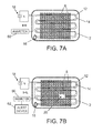
- FIGS. 7A and 7B are diagrams representing top views of a blunt impact indicator system in accordance with another embodiment, comprising a substrate 2 coated with rupturable microspheres 6 filled with electrically conductive fluid, a pair of serpentine electrical conductors 12 and 14 which are not electrically coupled to each other (indicated by open circuit 16) when microspheres 6 are intact, and a voltage supply 18 (e.g., a battery).
- the electrical conductors 12 and 14 may comprise wires or other current paths embedded in or printed on the substrate 2.
- FIG. 7B shows the system after some microspheres have been ruptured and electrically conductive fluid has been released to form a puddle or collection 20 of electrically conductive fluid. If the extent of the electrically conductive puddle or collection 20 is sufficient to electrically couple the electrical conductors 12 and 14 to each other, a circuit across the power and ground terminals of the voltage supply 18 will be closed.
- the electrical current I I d flowing through the completed circuit can be detected by an ammeter 60 (or other current detector), which sends an alert signal to an alert device 62 to indicate an impact above a threshold defined by the microsphere shell strength.
- the electrical current I d when the potential difference across the terminals of the voltage supply 18 (i.e., the terminal voltage) is constant, the electrical current I d will be inversely proportional to the resistance of the completed circuit. That resistance, in turn, is directly proportional to the length of the completed circuit, which means that the electrical current I d will be inversely proportional to the length of the completed circuit. If the positions of the wires are mapped, then the location of the impact can be determined from the current level measured by the ammeter 60.
- FIG. 8 shows a process for providing a measure of the level (i.e., magnitude) and location of a blunt impact without direct visual indication using the system shown in FIGS. 7A and 7B .
- the sensing state is on (state 22).
- an impact has occurred (event 24).
- the response of the system will depend on whether the impact is above the threshold for microsphere breakage or not, as indicated in decision block 26 in FIG. 8 . If the microspheres have not ruptured, then no notification is given (option 28) and the sensing state remains on (state 22).
- the electrically conductive fluid inside the hollow microspheres will disperse around the impact site (event 30). If a sufficient volume of electrically conductive fluid has been dispersed, then the electrically conductive fluid will create a current path between the power and ground wires which form the voltage terminals (event 32). The resulting electrical current in the completed circuit (i.e., loop) is detected by the current detector (step 34), which outputs a signal 36 indicating that an impact in excess of the threshold has occurred.
- the positions of the electrical conductors e.g., wires
- the current detector is in the form of an ammeter capable of measuring the current level in the completed circuit
- that ammeter will output a signal indicating the current level to an impact location processor.
- the impact location processor can input the current level into a look-up table that determines the location 40 of the impact relative to the mapped wires (step 38).
- a DC voltage supply 18 (e.g., a battery that is off-board of the structure) is indicated in FIGS. 7A and 7B , with an in-line means to sense the current. The impact completes the circuit between the twin serpentine electrical conductors 12 and 14. Otherwise there is no circuit and no current measured. Since alternating current has less voltage drop over a line than direct current, a more efficient method would be to plug into an AC generator of some type that is off the structure.
- FIG. 9 is a diagram representing a top view of a blunt impact indicator in accordance with an alternative embodiment.
- This blunt impact indicator works on the same principle (i.e., breaking microspheres to release electrically conductive fluid at an impact site to complete an electrical circuit) as the previous embodiment depicted in FIGS. 7A and 7B , but on a smaller scale.
- the embodiment depicted in FIG. 9 comprises a multiplicity of passive RFID chips 42a-42d adhered to and distributed over a surface of a substrate (i.e., a tape or an applique).
- a multiplicity of hollow microspheres 6 are adhered to or embedded in a surface of the substrate, with respective pluralities of microspheres 6 overlying respective RFID chips 42a-42d.
- the microspheres at the impact site will rupture, releasing electrically conductive fluid 20 in an area that may overlap one or more RFID chips 42a-42d.
- each passive RFID chip 42 preferably comprises an RFID integrated circuit 64 connected to a pair of serpentine electrical conductors 12 and 14 which, in the absence of electrically conductive fluid therebetween, are not electrically connected to each other.
- the electrical conductors 12 and 14 form a completed circuit, enabling these electrical conductors to serve as both antenna coils for communication with an RFID reader and sensing coils for detecting local areas in which impacts above a specified threshold have occurred.
- the threshold is preferably a function of the burst strength of the shells of the microspheres 8.
- the RFID integrated circuit 64 performs the following functions: storing and processing information, modulating and demodulating a radio-frequency (RF) signal, collecting DC power from the incident reader signal, and other specialized functions.
- Unique RFID tag information is stored in a non-volatile memory for each RFID chip.
- the RFID integrated circuit 64 includes either chip-wired logic or a programmed or programmable data processor for processing data.
- FIG. 10 shows an embodiment in which the electrical conductors 12 and 14 are incorporated within the RFID chip 42, it is also possible to have the electrical conductors 12 and 14 printed on the tape or applique to which the RFID chips are attached. Blunt impact indicators in accordance with this alternative embodiment can provide more coverage using fewer RFID chips.
- the electrical conductors 12 and 14 Upon the release of electrically conductive fluid from the hollow microspheres 8, the electrical conductors 12 and 14 will form a completed circuit in the manner previously described with reference to FIG. 7B . Again the magnitude of the current flowing in the completed circuit will be inversely proportional to the length of completed circuit.
- the response of the RFID integrated circuit 64 is changed by the released conductive fluid.
- the passive RFID chip 42 When queried, the passive RFID chip 42 will have a different frequency response due to a different impedance in the electrical conductors 12 and 14.
- each RFID chip 42a-42d is of the passive variety.
- the electrical conductors 12 and 14 (see FIG. 10 ) of an RFID chip 42 pick up RF signals output by the scanning antennae and then return the signal with some additional data, such as a unique serial number or other customized information.
- the serpentine electrical conductors 12 and 14 generate an electromagnetic field from which the RFID chip draws power, thereby energizing its circuits.
- the transceiver of the RFID circuit 64 then sends identifying information encoded in and read from the non-volatile memory.
- the RFID chips may be of the active type, meaning that each chip is powered by its own voltage supply (e.g., a battery).
- FIG. 11 shows components of a system comprising an RFID integrated circuit 64 powered by a voltage supply 18 and an RFID reader 66 capable of receiving sensor data transmitted by the RFID integrated circuit 64.
- an RFID chip adhered to the monitored structure within an impact area will have a different frequency response due to a change in impedance in the electrical conductors 12 and 14.
- the electrical conductors 12 and 14 when electrically connected, serve as both impact sensing coils and an antenna for communication with the RFID reader 66.
- the RFID reader 66 emits radio waves depending upon its power output and the radio frequency used.
- the RFID integrated circuit 64 detects the reader's activation signal.
- the RFID reader 66 decodes the chip identification data encoded in the non-volatile memory of the RFID integrated circuit 64 and that chip identification data is passed (along with date representing the changed frequency response of the RFID chip) to a host computer for processing.
- the identities of any RFID chips having frequency responses indicative of a blunt impact can be processed to determine their locations and the extent of the impact area.
- FIG. 12 A blunt impact indicator in accordance with an alternative embodiment is schematically depicted in FIG. 12 .
- this indicator system may incorporate a layer or coating having a multiplicity of hollow microspheres 6 (filled with colored fluid) embedded therein, for a purpose to be described later.
- a serpentine electrical conductor 44 made of breakable material e.g., wire
- a substrate 2 e.g., a tape or an appliqué
- a grid of electrical conductors having some other geometry can be employed.
- the serpentine electrical conductor 44 has a pair of terminals respectively connected to the voltage terminals of a power supply 50. Therefore, when the serpentine electrical conductor 44 is completely intact, an electrical current flows through a continuity indicator 49 by way of electrical conductors 48, 44 and 46 (which are connected in series).
- the continuity indicator 49 could be as simple as a light bulb or LED or more complex, as in a computerized program that is activated when the voltage drops from the loss of continuity.
- the continuity indicator 49 indicates to the technician that a blunt impact event has occurred, but does not indicate the location or extent of the impact site.
- any impact that exerts sufficient pressure will also cause one or more microspheres 6 to rupture, in which case released colored fluid provides to the technician a visual indication of the location and extent of the impact site.
- the breakable electrical conductors may take the form of an electrically conductive mesh on a substrate adhered to a structure.
- the area of breakage can be detected using an induction coil alone or in conjunction with a thermal imaging camera, as previously described.
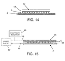
- FIG. 14 is a diagram representing a sectional view of a blunt impact indicator using fluid-filled microspheres in accordance with another embodiment.
- the indicator comprises: a substrate 2 (i.e., a tape or appliqué) which will be adhered to a surface of a structure to be monitored; a multiplicity of hollow microspheres 6 distributed in a coating or layer of material (not shown) which is laminated to the substrate 2; a sheet of pH-sensitive paper 54 which is laminated to the coating or layer containing embedded microspheres 6; and a transparent protective layer 52 which covers and protects the pH-sensitive paper 54.
- a substrate 2 i.e., a tape or appliqué
- a multiplicity of hollow microspheres 6 distributed in a coating or layer of material (not shown) which is laminated to the substrate 2
- a sheet of pH-sensitive paper 54 which is laminated to the coating or layer containing embedded microspheres 6
- a transparent protective layer 52 which covers and protects the pH-sensitive paper 54.
- the hollow microspheres 6 are filled with fluid having a pH level that will produce a color change on the pH-sensitive paper 54 that is visible under normal lighting or other lighting (UV, IR, etc.) when fluid is released from ruptured microspheres. If all of the shells of microspheres 6 have the same burst strength, then the portion of the pH-sensitive paper 54 which changes color will indicate the location and extent of an area in which the pressure exerted upon impact exceed a threshold corresponding to the burst strength.
- the shells of the hollow microspheres 6 may have different burst strengths and be filled with fluids having different pH levels.
- a first multiplicity of microspheres having a relatively low burst strength can be filled with fluid having a first pH level
- a second multiplicity of microspheres having a relatively high burst strength can be filled with fluid having a second pH level different than the first pH level. If the indicator is subjected to an impact sufficient to rupture the first multiplicity of microspheres but not rupture the second multiplicity of microspheres, then only fluid having the first pH level will be released, thereby causing the pH-sensitive paper 54 to change coloration from its original color to a first color.
- the indicator is subjected to an impact sufficient to rupture the first and second multiplicities of microspheres, then fluid having the first pH level and fluid having the second pH level will be released, thereby causing the pH-sensitive paper 54 to change coloration from its original color to a second color different than the first color.
- variations in rupture resistance (i.e., burst strength) of the microsphere shells may be achieved by varying the thickness of the walls in the respective multiplicities of microspheres.
- the wall thickness of the microspheres of the first multiplicity may be less than the wall thickness of the microspheres of the second multiplicity.
- variations in the rupture resistance of the microsphere shells may be achieved using alternative methods or techniques known by those skilled in the art.
- the leaked fluid may both mark the location and indicate the magnitude of the blunt impact force which was applied to the surface.
- the microspheres may be filled with clear UV or IR fluorescing dyes which, when released, are not visible to the naked eye, but can be found using UV or IR light.
- a clear fluid is contained inside the microspheres, which clear fluid, when released, only becomes visible when chemically activated by a developer spray applied by the inspector.
- the microspheres contain at least two separate liquids that react when they come in contact with each other, creating a colored indicator.
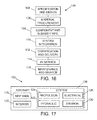
- FIG. 15 is a diagram representing a sectional view of a portion of a blunt impact indicator tape in accordance with yet another embodiment.
- a multiplicity of hollow microspheres 6, filled with electrically conductive fluid, are embedded in a layer of dielectric material (not shown), which dielectric layer is sandwiched between a pair of mutually confronting electrically conductive layers 56 and 58, which form a large capacitor.
- the electrically conductive layers 56 and 58 are respectively electrically coupled to the voltage terminals of a power supply 50 and to respective terminals of a continuity indicator 49 by way of electrical connectors 46 and 48.
- the continuity indicator 49 may be a light bulb or LED or may be a computerized program that is activated when electrical current flows through the completed circuit.
- the microspheres may be filled with clear UV or IR fluorescing dyes, which are released, and are not visible to the naked eye, but can be found using UV or IR light; or they may be filled with a clear fluid, which when released, only becomes visible when chemically activated by a developer spray applied by the inspector.
- the microspheres may be filled with at least two liquids which are separate prior to microsphere rupture and then react with each other when brought into contact with each other, thereby creating a colored (i.e., visible) indicator.
- exemplary method 100 may include specification and design 104 of the aircraft 102 and material procurement 106.
- component and subassembly manufacturing 108 and system integration 110 of the aircraft 102 takes place.
- the aircraft 102 may go through certification and delivery 112 in order to be placed in service 114.
- routine maintenance and service 116 which may also include modification, reconfiguration, refurbishment, and so on).
- a system integrator may include without limitation any number of aircraft manufacturers and major-system subcontractors; a third party may include without limitation any number of venders, subcontractors, and suppliers; and an operator may be an airline, leasing company, military entity, service organization, and so on.
- the aircraft 102 produced by exemplary method 100 may include an airframe 118 with a plurality of systems 120 and an interior 122.
- high-level systems 120 include one or more of the following: a propulsion system 124, an electrical system 126, a hydraulic system 128, and an environmental control system 130. Any number of other systems may be included.
- the systems and methods embodied herein may be employed during one or more of the stages of the production and service method 100.
- one or more system embodiments, method embodiments, or a combination thereof may be utilized during the production stages 108 and 110, for example, by providing a measure of the magnitude and location of a high-energy blunt impact on a workpiece during the process of assembling an aircraft 102.
- one or more of system embodiments, method embodiments, or a combination thereof may be utilized while the aircraft 102 is in service, for example and without limitation, during maintenance and service 116.
- the phrase "disposed in proximity to a surface of a substrate" in connection with microspheres should be construed to encompass at least the following species: (1) attaching microspheres to the surface; and (2) embedding microspheres in a coating which is applied on the surface.
Abstract
Description
- This disclosure generally relates to systems and methods for monitoring or indicating high-energy impacts on a structure. More particularly, this disclosure relates to systems and methods for measuring the magnitude and location of a high-energy impact event.
- When damage to a structural component is suspected, it is customary to evaluate the structural integrity of the possibly damaged component using non-destructive evaluation (NDE) techniques. When NDE techniques are used, it may be difficult to determine specific points of damage quickly because large areas of the structure may need to be scanned. Therefore, it is desirable to have a technique whereby the precise location of damage can be easily determined.
- In the aviation industry, an aircraft may be vulnerable to high-energy blunt impacts from support vehicles and ground support equipment such as cargo belt loaders, luggage carts, aircraft refuelers, catering vehicles, ground power units, airport buses and passenger boarding stairs. In response to any indication that a high-energy blunt impact has occurred, the customary first maintenance procedure is to perform a non-destructive evaluation of the impacted area sufficient to determine an appropriate disposition, e.g., repair the damage to the aircraft.
- Although methods are known for producing a visual indication of an on-aircraft high-energy blunt impact to a casual observer by the placement of impact tape (comprising rupturable microspheres filled with colored indicator fluid) on the surface of an aircraft structure which is vulnerable to such impacts, in some instances visual indication of surface damage may not be wanted.
- There is scope for improvements in existing technology for monitoring or indicating high-energy blunt impacts on structures such as aircraft.
- The subject matter disclosed herein is directed to systems and methods using fluid-filled hollow microspheres to assist in monitoring or indicating high-energy blunt impacts on structures such as aircraft. A multiplicity of microspheres may be adhered to or embedded in a coating applied on a surface of a substrate (e.g., a tape or an appliqué), which substrate in turn can be adhered to a surface of a structure to be monitored. The microspheres are designed to rupture at one or more specified pressure thresholds. In some embodiments, the microspheres are filled with electrically conductive fluid which, if released from ruptured microsphere, changes the electromagnetic state of the substrate. In response to the detection of a sufficiently large change in the electromagnetic state of the substrate, a blunt impact indication is generated. The impact site may then undergo non-destructive inspection.
- One aspect of the subject matter disclosed in detail below is a blunt impact indicator device comprising: a substrate comprising first and second surfaces; and a multiplicity of rupturable shells disposed in proximity to said first surface of said substrate, the shells having an electrically conductive fluid disposed in an internal volume of the shells. The shells can be hollow microspheres made of dielectric material. The substrate may be in the form of a tape or an appliqué.
- In accordance with one implementation, the blunt impact indicator device further comprises: first and second electrical conductors; and a voltage supply connected to the first and second electrical conductors, wherein the first and second electrical conductors are disposed on one side of the first surface of the substrate and spaced apart so that the first and second electrical conductors will be electrically coupled to each other by electrically conductive fluid escaped from the multiplicity of shells and will not be electrically coupled to each other in the absence of electrically conductive fluid from the multiplicity of shells. A meter may be provided for measuring a magnitude of electrical current flowing through the first electrical conductor.
- In accordance with another implementation, the blunt impact indicator device further comprises: first and second electrical conductors which are not electrically coupled to each other in the absence of electrically conductive fluid; and a radio-frequency identification circuit connected to the first and second electrical conductors, wherein the first and second electrical conductors are disposed on one side of the first surface of the substrate and configured and spaced so that the first and second electrical conductors can be electrically coupled to each other in the presence of electrically conductive fluid released from the multiplicity of shells. In this implementation, the radio-frequency identification circuit may comprise a transceiver coupled to the first and second electrical conductors and non-volatile memory storing information which uniquely identifies the radio-frequency identification circuit.
- In accordance with a further implementation, the blunt impact indicator device further comprises: a first layer of electrically conductive material disposed on the first surface of the substrate; a second layer of electrically conductive material overlying the first layer electrically conductive material with a space therebetween, the multiplicity of shells being disposed in the space; and a voltage supply connected to the first and second layers of electrically conductive material, wherein the first and second layers of electrically conductive material are spaced apart so that the first and second layers of electrically conductive material will be electrically coupled to each other when wetted by electrically conductive fluid released from the multiplicity of shells and will not be electrically coupled to each other in the absence of electrically conductive fluid from the multiplicity of shells.
- Another aspect of the subject matter disclosed in detail below is a blunt impact indicator device comprising: a substrate; a breakable electrical conductor disposed on or embedded in the substrate and having first and second terminals; a voltage supply connected to the first and second terminals of the breakable electrical conductor; and a continuity indicator electrically connected to the breakable electrical conductor. Optionally, the blunt impact indicator device further comprises: a multiplicity of rupturable shells disposed in proximity to a surface of the substrate, the shells being distributed over an area encompassing the breakable electrical conductor, each shell having an internal volume; and an electrically conductive fluid disposed in the internal volumes of respective shells of the multiplicity of shells.
- A further aspect of the subject matter disclosed herein is a method for monitoring a structure for damage due to blunt impact, comprising: attaching a substrate to a surface of the structure, the substrate comprising a multiplicity of rupturable shells adhered thereto or embedded therein, each shell having an internal volume, and an electrically conductive fluid disposed in the internal volumes of respective shells of the multiplicity of shells; and detecting a change in electrical conductivity of the substrate. In accordance with one embodiment, the step of detecting a change in electrical conductivity of the substrate comprises: placing a coil in proximity to the substrate; causing alternating current to flow through the coil during first and second time intervals, a magnitude of the alternating current and a distance separating the coil from the substrate being selected for inducing eddy currents in the substrate; and measuring any difference between a first impedance of the coil during the first time interval and a second impedance of the coil during the second time interval. Optionally, the step of detecting a change in electrical conductivity of the substrate further comprises: determining whether a difference between the first and second impedances is greater than a specified threshold; and performing non-destructive inspection in the area of the structure which the coil is in proximity to if the difference between the first and second impedances is greater than the specified threshold.
- Yet another aspect is a method for monitoring a structure for damage due to blunt impact, comprising: attaching a substrate to a surface of a structure, the substrate comprising a multiplicity of rupturable shells disposed in proximity to a surface of the substrate, each shell having an internal volume, and an electrically conductive fluid disposed in the internal volumes of respective shells of the multiplicity of shells; and detecting a change in thermal state of the substrate which is indicative of escape of electrically conductive fluid from the shells. In accordance with one embodiment, the step of detecting a change in thermal state of the substrate comprises performing the following steps during first and second intervals of time which do not overlap: (a) placing a coil in proximity to the substrate; (b) causing alternating current to flow through the coil while the coil is in proximity to the substrate; (c) after the substrate has been heated in an area during step (b) due to eddy currents induced in the electrically conductive fluid by the alternating current in the coil, removing the coil; and (d) after the coil has been removed, acquiring a thermal image of the area of the heated substrate using a thermal imaging camera. Preferably, the step of detecting a change in thermal state of the substrate further comprises: comparing a first thermal image acquired during the first interval of time with a second thermal image acquired during the second interval of time. The method may further comprise displaying an image representing differences between the first and second thermal images.
- Another aspect is a method for monitoring a structure for damage due to blunt impact, comprising: placing a radio-frequency identification circuit and first and second serpentine electrical conductors on a substrate, the first and second serpentine electrical conductors having respective first terminals electrically connected to respective terminals of the radio-frequency identification circuit and respective second terminals which are not electrically connected to each other; placing a multiplicity of rupturable shells over the first and second serpentine electrical conductors, each shell having an internal volume at least partially filled with electrically conductive fluid; and interrogating the radio-frequency identification circuit by transmitting a radio-frequency signal through a volume of space intersected by radio-frequency identification circuit, wherein any response to the interrogation by the radio-frequency identification circuit will have a frequency which is a function of an impedance of an antenna formed if the first and second serpentine electrical conductors are electrically coupled to each other by electrically conductive fluid escaped from the multiplicity of shells.
- A further aspect of the disclosed subject matter is a blunt impact indicator device, comprising: a substrate having a surface; a first multiplicity of rupturable shells disposed in proximity to the surface of the substrate, each shell of the first multiplicity having an internal volume; a first fluid having a first pH level disposed in the internal volumes of respective shells of the first multiplicity of shells; and a layer of pH-sensitive material disposed adjacent to the first multiplicity of rupturable shells. This blunt impact indicator device may further comprise: a second multiplicity of rupturable shells intermingled with the first multiplicity of rupturable shells, each shell of the second multiplicity having an internal volume; and a second fluid having a second pH level, different than the first pH level, disposed in the internal volumes of respective shells of the second multiplicity of shells.
- Aspects of the subject matter disclosed further include:
- A1. A blunt impact indicator device, comprising:
- a substrate comprising first and second surfaces; and
- a multiplicity of rupturable shells disposed in proximity to said first surface of said substrate, the shells having an electrically conductive fluid disposed in an internal volume of the shells.
- A2. The blunt impact indicator device as recited in A1, wherein said shells are hollow microspheres made of dielectric material.
- A3. The blunt impact indicator device as recited in any of A1-A2, further comprising a layer of adhesive on said second surface of said substrate.
- A4. The blunt impact indicator device as recited in any of A1-A3, wherein said substrate is in the form of a tape or an applique.
- A5. The blunt impact indicator device as recited in any of A1-A4, further comprising:
- first and second electrical conductors; and
- a voltage supply connected to said first and second electrical conductors,
- wherein said first and second electrical conductors are disposed on one side of said first surface of said substrate and spaced apart so that said first and second electrical conductors will be electrically coupled to each other by electrically conductive fluid escaped from said multiplicity of shells and will not be electrically coupled to each other in the absence of electrically conductive fluid from said multiplicity of shells.
- A6. The blunt impact indicator device as recited in A5, wherein said first and second electrical conductors are serpentine.
- A7. The blunt impact indicator device as recited in any of A5-A6, further comprising a meter for measuring a magnitude of electrical current flowing through said first electrical conductor.
- A8. The blunt impact indicator device as recited in any of A1-A4, further comprising:
- first and second electrical conductors which are not electrically coupled to each other in the absence of electrically conductive fluid; and
- a radio-frequency identification circuit connected to said first and second electrical conductors,
- wherein said first and second electrical conductors are disposed on one side of said first surface of said substrate and configured and spaced so that said first and second electrical conductors can be electrically coupled to each other in the presence of electrically conductive fluid released from said multiplicity of shells.
- A9. The blunt impact indicator device as recited in A8, wherein said radio-frequency identification circuit comprises a transceiver coupled to said first and second electrical conductors and non-volatile memory storing information which uniquely identifies said radio-frequency identification circuit.
- A10. The blunt impact indicator device as recited in A1-A4, further comprising:
- a first layer of electrically conductive material disposed on said first surface of said substrate;
- a second layer of electrically conductive material overlying said first layer electrically conductive material with a space therebetween, said multiplicity of shells being disposed in said space; and
- a voltage supply connected to said first and second layers of electrically conductive material,
- wherein said first and second layers of electrically conductive material are spaced apart so that said first and second layers of electrically conductive material will be electrically coupled to each other when wetted by electrically conductive fluid released from said multiplicity of shells and will not be electrically coupled to each other in the absence of electrically conductive fluid from said multiplicity of shells.
- B1. A blunt impact indicator device, comprising:
- a substrate;
- a breakable electrical conductor disposed on or embedded in said substrate and having first and second terminals;
- a voltage supply connected to said first and second terminals of said breakable electrical conductor; and
- a continuity indicator electrically connected to said breakable electrical conductor.
- B2. The blunt impact indicator device as recited in B1, wherein said breakable electrical conductor has a serpentine or spiral configuration.
- B3. The blunt impact indicator device as recited in any of B1-B2, further comprising:
- a multiplicity of rupturable shells disposed in proximity to a surface of said substrate, said shells being distributed over an area encompassing said breakable electrical conductor, each shell having an internal volume; and
- an electrically conductive fluid disposed in the internal volumes of respective shells of said multiplicity of shells.
- C1. A method for monitoring a structure for damage due to blunt impact, comprising:
- attaching a substrate to a surface of the structure, the substrate comprising a multiplicity of rupturable shells adhered thereto or embedded therein, each shell having an internal volume, and an electrically conductive fluid disposed in the internal volumes of respective shells of said multiplicity of shells; and
- detecting a change in electrical conductivity of the substrate.
- C2. The method as recited in C1, wherein said detecting a change in electrical conductivity of the substrate comprises:
- placing a coil in proximity to the substrate;
- causing alternating current to flow through the coil during first and second time intervals, a magnitude of said alternating current and a distance separating the coil from the substrate being selected for inducing eddy currents in the substrate; and
- measuring any difference between a first impedance of the coil during said first time interval and a second impedance of the coil during said second time interval.
- C3. The method as recited of C2, wherein said detecting a change in electrical conductivity of the substrate further comprises:
- determining whether a difference between said first and second impedances is greater than a specified threshold; and
- performing non-destructive inspection in the area of the structure which the coil is in proximity to if said difference between said first and second impedances is greater than said specified threshold.
- D1. A method for monitoring a structure for damage due to blunt impact, comprising:
- attaching a substrate to a surface of a structure, the substrate comprising a multiplicity of rupturable shells disposed in proximity to a surface of the substrate, each shell having an internal volume, and an electrically conductive fluid disposed in the internal volumes of respective shells of said multiplicity of shells; and
- detecting a change in thermal state of the substrate.
- D2. The method as recited in D1, wherein said detecting a change in thermal state of the substrate comprises performing the following steps during first and second intervals of time which do not overlap:
- (a) placing a coil in proximity to the substrate;
- (b) causing alternating current to flow through the coil while the coil is in proximity to the substrate;
- (c) after the substrate has been heated in an area during step (b) due to eddy currents induced in the electrically conductive fluid by the alternating current in the coil, removing the coil; and
- (d) after the coil has been removed, acquiring a thermal image of the area of the heated substrate using a thermal imaging camera.
- D3. The method as recited in D2, wherein said detecting a change in thermal state of the substrate further comprises:
- comparing a first thermal image acquired during said first interval of time with a second thermal image acquired during said second interval of time.
- D4. The method as recited in claim D3, further comprising displaying an image representing differences between said first and second thermal images.
- E1. A method for monitoring a structure for damage due to blunt impact, comprising:
- placing a radio-frequency identification circuit and first and second serpentine electrical conductors on a substrate, the first and second serpentine electrical conductors having respective first terminals electrically connected to respective terminals of the radio-frequency identification circuit and respective second terminals which are not electrically connected to each other;
- placing a multiplicity of rupturable shells over the first and second serpentine electrical conductors, each shell having an internal volume at least partially filled with electrically conductive fluid; and
- interrogating the radio-frequency identification circuit by transmitting a radio-frequency signal through a volume of space intersected by radio-frequency identification circuit,
- wherein any response to the interrogation by the radio-frequency identification circuit will have a frequency which is a function of an impedance of an antenna formed if the first and second serpentine electrical conductors are electrically coupled to each other by electrically conductive fluid escaped from the multiplicity of shells.
- F1. A blunt impact indicator device, comprising:
- a substrate having a surface;
- a first multiplicity of rupturable shells disposed in proximity to said surface of said substrate, each shell of said first multiplicity having an internal volume;
- a first fluid having a first pH level disposed in the internal volumes of respective shells of said first multiplicity of shells; and
- a layer of pH-sensitive material disposed adjacent to said first multiplicity of rupturable shells.
- F2. The blunt impact indicator device as recited in F1, further comprising:
- a second multiplicity of rupturable shells intermingled with said first multiplicity of rupturable shells, each shell of said second multiplicity having an internal volume; and
- a second fluid having a second pH level, different than said first pH level, disposed in the internal volumes of respective shells of said second multiplicity of shells.
- Other aspects of systems and methods for monitoring or indicating high-energy blunt impacts on structures such as aircraft are disclosed and claimed below.
-
-
FIG. 1 is a diagram representing a side view of a blunt impact indicator tape comprising rupturable microspheres filled with electrically conductive fluid in accordance with some embodiments. -
FIG. 2 is a diagram representing a sectional view of a portion of a blunt impact indicator tape in accordance with an alternative embodiment. -
FIG. 3 is a block diagram showing components of an apparatus for nondestructive inspection of a structure using a probe comprising an induction coil for detecting magnetic field disturbances caused by the escape of electrically conductive fluid from hollow microspheres distributed on a surface or in a surface layer of the structure. -
FIG. 4 is a block diagram showing components of an automated scanning apparatus for nondestructive inspection of a structure using a probe comprising an induction coil for detecting magnetic field disturbances caused by the escape of electrically conductive fluid from hollow microspheres distributed on a surface or in a surface layer of the structure. -
FIG. 5 is a diagram illustrating the use of an induction coil to detect magnetic field disturbances caused by the escape of electrically conductive fluid from hollow microspheres distributed in a surface layer of a structure. -
FIG. 6 is a diagram showing components of a system for generating eddy currents in a structure containing electrically conductive fluid-filled microspheres and capturing thermal images before and after a blunt impact event in accordance with an alternative embodiment. -
FIGS. 7A and 7B are diagrams representing top views of a blunt impact indicator system in accordance with another embodiment, comprising a substrate coated with rupturable microspheres filled with electrically conductive fluid, electrical conductors which are not electrically coupled when the microspheres are intact, and a voltage supply.FIG. 7A shows the system when all microspheres are intact, whileFIG. 7B shows the system after some microspheres have been ruptured and electrically conductive fluid has been released. -
FIG. 8 is a flowchart showing steps of a method for providing a measure of the level (i.e., magnitude) and location of a blunt impact without direct visual indication using the system shown inFIGS. 7A and 7B . -
FIG. 9 is a diagram representing a top view of a blunt impact indicator comprising a multiplicity of passive RFID chips in accordance with an alternative embodiment. -
FIG. 10 is a diagram representing a top view (with a magnified scale) of a passive RFID chip of the type incorporated in the blunt impact indicator depicted inFIG. 9 . -
FIG. 11 is a block diagram showing components of a system comprising an RFID reader capable of reading blunt impact data stored in active RFID chips installed on a structure. -
FIG. 12 is a diagram representing a top view of a blunt impact indicator comprising a matrix of breakable electrical conductors (e.g., wires) in accordance with another embodiment. -
FIG. 13 is a diagram representing a sectional view of the blunt impact indicator depicted inFIG. 12 . -
FIG. 14 is a diagram representing a sectional view of a blunt impact indicator comprising pH-sensitive paper and hollow microspheres filled with fluid having a pH level that will produce a color change that is visible under normal lighting or other lighting (UV, IR, etc.) when the fluid is released from ruptured microspheres. -
FIG. 15 is a diagram representing a sectional view of a portion of a blunt impact indicator tape in accordance with a further embodiment. -
FIG. 16 is a flow diagram of an aircraft production and service methodology. -
FIG. 17 is a block diagram showing systems of an aircraft. - Reference will hereinafter be made to the drawings in which similar elements in different drawings bear the same reference numerals.
- Various embodiments of blunt impact indicators that employ fluid-filled microspheres will now be described in detail for purposes of illustration only. These blunt impact indicators may be applied on a surface of a structure in the form of a substrate (e.g., a tape or an applique) with an adhesive backing. The microspheres may be adhered to the substrate or embedded in a coating applied on the substrate.
- A first illustrative embodiment of a blunt impact indicator of the foregoing type is schematically depicted in
FIG. 1 . This blunt impact indicator comprises asubstrate 2 having a multiplicity ofhollow microspheres 6 attached to and distributed on one surface ofsubstrate 2 by means of alayer 4 of adhesive material (hereinafter "adhesive layer 4"). Optionally themicrospheres 6 are covered by acover layer 52. - The
substrate 2 may take different forms. In some cases, thesubstrate 2 may take the form of a tape comprising a thin strip of plastic material. In other cases, the substrate may take the form of an appliqué comprising a thin sheet of plastic material. The terms "tape" and "appliqué", as used herein, respectively refer to substrates having different ranges of width, with the width of a tape being less than the width of an appliqué. Tape or applique can be cut to fit and affixed to the surface of a structure, for example, an aircraft. - Alternatively, as shown in the sectional view of
FIG. 2 , themicrospheres 6 can be embedded in acoating 51 applied on the exterior surface of asubstrate 2. Theadhesive layer 4 is adhered to afirst surface 2a ofsubstrate 2, while anadhesive backing 10 is adhered to asecond surface 2b ofsubstrate 2. Optionally, thesubstrate 2 may further comprise a release film (not shown) which covers and protects theadhesive backing 10 prior to thesubstrate 2 being adhered to a surface of a structure (not shown inFIGS. 1 and 2 ). - As seen in
FIG. 2 , eachmicrosphere 6 comprises ashell 8 that bounds an interior volume when theshell 8 is intact. Eachshell 8 can be made of dielectric material having a specified burst strength. In some applications, theshells 8 may have approximately the same burst strength; in other applications different subgroups ofshells 8 may have different burst strengths. - Still referring to
FIG. 2 , the interior volume of eachshell 8 is filled (or partially filled) with electricallyconductive fluid 20. When an underlying structure (not shown inFIGS. 1 and 2 ), to which the blunt impact indicator is attached, is subjected to a blunt impact of sufficient magnitude to cause at least some of the multiplicity ofshells 8 to rupture, some or all of the electricallyconductive fluid 20 will bleed, leak or otherwise escape from the ruptured shells to form a puddle or other collection of fluid in the area of the blunt impact for purposes which will be hereinafter described. - As depicted in
FIG. 2 , the blunt impact indicator device preferably comprises a multiplicity of closely packedhollow microspheres 6. Thedielectric shells 8 ofmicrospheres 6 may be made of glass, plastic or ceramic. However, it is not essential to practice of the invention that theshells 8 be spherical. Other hollow structures (i.e., not spherical) can be employed. The electricallyconductive fluid 20 may be any suitable fluid base, including but not limited to a colloidal graphite suspension (e.g., a preparation of fine, pure colloidal graphite in water), which can be diluted with other additives (surfactants, solvents, anti-freeze, etc.) to meet the requirements of a particular environmental envelope. - The release of electrically
conductive fluid 20 can change the electromagnetic behavior of the structure in the area of blunt impact. More specifically, the electromagnetic behavior of the structure after electrically conductive fluid has escaped from ruptured microspheres in an impact area will differ from the electromagnetic behavior of the same area when the microspheres are intact (in which case the individual volumes of electrically conductive fluid inside the hollow microspheres are insulated from each other by the intact dielectric shells). This change in electromagnetic properties due to blunt impact can be detected in different ways. -
FIG. 3 is a block diagram showing components of an apparatus for nondestructive inspection of a structure using aprobe 80 comprising an induction coil (not shown inFIG. 3 ) connected to apower source 82 and to adetection system 84 which detects magnetic field disturbances caused by the escape of electrically conductive fluid fromhollow microspheres 6 distributed on a surface or in a surface layer of the inspected structure. The inspected structure may be a skin on a portion of an aircraft, such as a fuselage. - In accordance with one embodiment, the
probe 80 is placed in proximity to the area being inspected. Then thepower source 82 is turned on. Thepower source 82 generates an alternating current at a specified frequency, which alternating current flows through the induction coil ofprobe 80. The resulting waves of electromagnetic radiation emanating from the coil in turn induce eddy currents in any electrically conductors in proximity (e.g., any electrically conductive fluid escaped from ruptured microspheres on a surface or in a surface layer of the structure being inspected). These eddy currents in turn generate more waves of electromagnetic radiation, thereby disturbing the magnetic field being produced by the driven induction coil. - Still referring to
FIG. 3 , thedetection system 84 may comprise circuitry (e.g., a processor) configured to quantify the disturbance or change in the magnetic field produced by the induction coil. In one example, the disturbance or change in magnetic field is detected through a change in the inductive reactance ofprobe 80. Thedetection system 84 may further include a display to present the changes in inductive reactance from disturbances to the magnetic field such that a technician can visualize those changes as he/she moves theprobe 80 over different sections of the structure being inspected. - In the example depicted in
FIG. 3 , probe 80 may be a hand-held unit that is moveable by the technician performing the inspection.Detection system 84 may be a hard-wired electronic circuit configured or a processor programmed to convert changes in the probe's inductive reactance, aftermicrospheres 6 have been ruptured, into electrical signals representing parametric data which can then be compared to reference parametric data, stored in memory, which was previously acquired when themicrospheres 6 were intact, i.e., pre-blunt impact event. -
FIG. 4 shows components of an automated scanning apparatus for nondestructive inspection of a structure using a probe comprising an induction coil. Again the induction coil can be used to detect magnetic field disturbances attributable to the presence of electrically conductive fluid leaked fromhollow microspheres 6 previously distributed on a surface or in a surface layer of the structure. In this embodiment, theprobe 80 is mounted to the end effector of anarm 86 of ascanner 88. The system further comprises acomputer 90, which controls thescanner 88 and receives inductive reactance data fromprobe 80 for presentation on adisplay screen 92.Scanner 88 may also provide a power source forprobe 80. - In the example depicted in
FIG. 4 , thecomputer 90 generates instructions to direct movement ofarm 86 byscanner 88 over and in proximity to the area to be inspected. The power source sends an alternating electric current through the induction coil ofprobe 80 at a specified frequency to generate a varying magnetic field that intensifies and diminishes as the direction of the current alternates. Again the magnetic field generated byprobe 80 causes eddy currents within any electrically conductive fluid escaped from themicrospheres 6 due to a blunt impact event, which eddy currents in turn cause disturbances or changes in the magnetic field being generated byprobe 80 as it moves in proximity to the area being inspected. The results of scanning different sections of the structure may be presented ondisplay screen 92. This display may be presented as a color-coded display, in which different magnetic field strengths are displayed in different colors. - The
probe 80 may be designed or configured to generate magnetic fields having a selected size and strength. In some examples, the size and strength of the magnetic field generated byprobe 80 may be configured or selected based on a number of different parameters, such as the frequency of the alternating current, the dimensions and geometry of the probe coil, and the diameter of the coil wire. These parameters and other parameters also may be used to select or generate a magnetic field having a specified shape. -
FIG. 5 is a diagram illustrating the use of aninduction coil 94 to generate a magnetic field M1 and then detect a magnetic field disturbance M2 due to the presence of a puddle or other collection of electricallyconductive fluid 96 which has escaped from ruptured microspheres (not shown) in an inspected area. (Onlyintact microspheres 6 are shown inFIG. 5 to avoid cluttering the depiction of a collection of electricallyconductive fluid 96 with ruptured shells.) In response tocoil 94 being driven with an alternating current, thecoil 94 generates a varying magnetic field M1, which is indicated for one instant of time by a half-dozen downward-pointing dashed curved arrows inFIG. 5 . The eddy currents induced in the electricallyconductive fluid 96 in turn generate a varying magnetic field disturbance M2, which is indicated for the same instant of time by a half-dozen upward-pointing dashed curved arrows inFIG. 5 . The magnetic field disturbance M2 will vary as the coil is moved over the area being inspected. The magnetic field disturbances M2 may be detected using a measurement circuit connected to the probe. The disturbances are detected in changes in the inductive reactance of thecoil 94. Reactance is a form of opposition that electronic components exhibit to the passage of alternating current because of capacitance or inductance. When alternating current passes through a component that has a reactance, energy is alternately stored in and released from a magnetic field or an electric field. In the case of a magnetic field, the reactance is inductive. - The
inductance coil 94 depicted inFIG. 5 can be used in any system of the types described above with reference toFIGS. 3 and 4 . Electricallyconductive fluid 96, when dispersed at blunt impact, can be detected using theinductance coil 94. The dielectric shells ofmicrospheres 6 may be designed with a burst strength which is a function of a specified pressure threshold. In that case, the blunt impact indicator device is capable of detecting any blunt impact that produces a pressure in excess of that threshold. Using an inductance coil to detect blunt impact events has the benefit that no indication of the blunt impact event is visible to a casual observer. Instead an electrical indication can be transmitted to a remote device accessible only to maintenance personnel and, in cases where the structure being inspected is an aircraft, optionally to the flight crew. - In accordance with an alternative implementation, the
coil 94 may be part of a hand-held conductive inspection apparatus of the type depicted and described inU.S. Patent No. 7,312,608 . -
FIG. 6 is a diagram showing components of a system in accordance with an alternative embodiment. The measurement method implemented by this system comprises the following steps performed before and after a blunt impact event: generating eddy currents in an area of a structure containing electrically conductive fluid-filled microspheres; removing the eddy current generator, and then capturing thermal images of the area which has been heated by the eddy currents. For the purpose of illustration,FIG. 6 depicts examination of a portion of acomposite aircraft fuselage 132 having an applique 96 (indicated by a dashed ellipse) with hollow microspheres adhered to or embedded in a coating on a surface thereof. The electrically conductive media in the hollow microspheres, when dispersed at impact, can be imaged using a high-power radio-frequency (RF)coil 134 to create eddy currents strong enough to raise the temperature locally, with the resulting temperature rise being imaged using a thermal imaging camera 136 (e.g., an infra-red camera). The resulting images may be displayed on adisplay monitor 140 which is electrically coupled to a data acquisition and controlcomputer system 138, the variations in color showing the area of blunt impact. - This thermal imaging method comprises placing the high-
power RF coil 134 in proximity to theapplique 96 and then activating the coil to generate an electromagnetic field. Excitation frequencies for the high-power RF coil 134 may be in the range of 100 to 400 kHz. This range has been found to create an electromagnetic field that penetrates composite material. It is well known that eddy currents are induced in a conductive medium by a changing magnetic field. For example, a changing magnetic field can result from relative motion of the coil and the conductive medium; or due to variations of the electromagnetic field with time. The stronger the applied electromagnetic field, or the greater the electrical conductivity of the conductive medium, or the greater the relative velocity of motion, the greater the eddy currents developed. In the application depicted inFIG. 6 , the eddy currents induced by the varying magnetic field will be different depending on whether or not any area of theapplique 96 has been impacted by a blunt object with sufficient pressure to rupture hollow microspheres in the impact area. As a result, the eddy currents in the impact area will be stronger than the eddy currents outside the impact area. The differences in the strengths of the eddy currents inside and outside the impact area will produce corresponding different degrees of heating. The coil's excitation current can be pulse width modulated to allow for controlled heating. - The method further comprises thermal imaging of the heated area. More specifically, a thermal image of the conductive medium is created to reveal electromagnetic state information about the electrically conductive media in the
applique 96. In the embodiment depicted inFIG. 6 , the thermal image is generated using athermal imaging camera 136. In other embodiments, the thermal image may be created by placing a thermographic film on the surface of the composite component. The thermographic film is temperature-sensitive and generates an optically viewable representation of the heated area. Such a thermographic film is described in detail inU.S. Patent No. 7,287,902 . - As shown in
FIG. 6 , the high-power RF coil 134 is powered by acontrollable power supply 142. Placing thepowered RF coil 134 in proximity to the composite skin surface offuselage 132 induces current flow in theapplique 96 and associated local heating of theapplique 96. Thethermal imaging camera 136 is directed at the skin surface with a field of view encompassing all or part of theapplique 96, to allow recording of the thermal gradient of theheated applique 96 after theRF coil 134 has been removed. A data acquisition and controlcomputer system 138 records the data from thethermal imaging camera 136 and provides control of thecontrollable power supply 142 for various thermal imaging techniques, as will be described in greater detail subsequently. - For certain embodiments with differential imaging processes, initial (e.g., pre-blunt impact event) and final (e.g., post-blunt impact event) images of the
applique 96 are captured. In each instance, power is applied to theinduction coil 134 and, in a hand-operated embodiment, the inspector/operator waves thecoil 134 over the area to be inspected. The desired motion of thecoil 134 and its distance from the skin surface are dependent on the power level, RF frequency, shape and size of thecoil 134. The coil's electro-magnetic field inductively generates eddy currents in any electrically conductive areas of theapplique 96 and underlying skin. The eddy currents generated in the electrically conductive materials are of sufficient strength to generate heat depending upon local electrical paths. Thethermal imaging camera 136 is used to image relative heating before and after a blunt impact event. The relative heating is determined for certain embodiments using differential thermal imaging by subtracting the initial image values from the final image values. - In the system depicted in
FIG. 6 , thethermal imaging camera 136 may comprise a focal plane array infra-red camera. The induced currents produced by thecoil 134 constitute the excitation technique, generating thermal gradients that reveal any differences in the electromagnetic behavior of respective examined areas. The induced current heating can be generated in a pulsed manner in order to allow for controlled heating without damaging the structure underlying theapplique 96. In addition, the frame captured by thethermal imaging camera 136 can be synchronized (by asynchronization unit 144 electrically coupled to the data acquisition and controlcomputer system 138 and to the controllable power supply 142) with the current pulse supplied to thecoil 134 so that an image can be obtained before the current is pulsed and then captured after the current has been pulsed. The data acquisition and controlcomputer system 138 is programmed to control both thethermal imaging camera 136 and thepower supply 142 as well as storage of data from the camera. Presentation of captured thermal imaging data is provided on thedisplay monitor 140 and stored in memory for additional processing. - In alternative embodiments employing an automated system, the induction coil motion is accomplished using a three-axis positioning device with motion along the skin surface, coil excitation and thermal imaging controlled by the computer control system for synchronization of the data.
-
FIGS. 7A and 7B are diagrams representing top views of a blunt impact indicator system in accordance with another embodiment, comprising asubstrate 2 coated withrupturable microspheres 6 filled with electrically conductive fluid, a pair of serpentineelectrical conductors microspheres 6 are intact, and a voltage supply 18 (e.g., a battery). Theelectrical conductors substrate 2.FIG. 7A shows the system when allmicrospheres 6 are intact and the current throughelectrical conductors FIG. 7B shows the system after some microspheres have been ruptured and electrically conductive fluid has been released to form a puddle orcollection 20 of electrically conductive fluid. If the extent of the electrically conductive puddle orcollection 20 is sufficient to electrically couple theelectrical conductors voltage supply 18 will be closed. The electrical current I = I d flowing through the completed circuit can be detected by an ammeter 60 (or other current detector), which sends an alert signal to analert device 62 to indicate an impact above a threshold defined by the microsphere shell strength. - In accordance with Ohm's Law, when the potential difference across the terminals of the voltage supply 18 (i.e., the terminal voltage) is constant, the electrical current I d will be inversely proportional to the resistance of the completed circuit. That resistance, in turn, is directly proportional to the length of the completed circuit, which means that the electrical current I d will be inversely proportional to the length of the completed circuit. If the positions of the wires are mapped, then the location of the impact can be determined from the current level measured by the
ammeter 60. -
FIG. 8 shows a process for providing a measure of the level (i.e., magnitude) and location of a blunt impact without direct visual indication using the system shown inFIGS. 7A and 7B . When a pair of electrical conductors are connected to the terminals of a voltage supply and not to each other, the sensing state is on (state 22). For the sake of illustration, it will be presumed that an impact has occurred (event 24). The response of the system will depend on whether the impact is above the threshold for microsphere breakage or not, as indicated indecision block 26 inFIG. 8 . If the microspheres have not ruptured, then no notification is given (option 28) and the sensing state remains on (state 22). Conversely, if the microspheres have ruptured, then the electrically conductive fluid inside the hollow microspheres will disperse around the impact site (event 30). If a sufficient volume of electrically conductive fluid has been dispersed, then the electrically conductive fluid will create a current path between the power and ground wires which form the voltage terminals (event 32). The resulting electrical current in the completed circuit (i.e., loop) is detected by the current detector (step 34), which outputs asignal 36 indicating that an impact in excess of the threshold has occurred. Furthermore, if the positions of the electrical conductors (e.g., wires) has been mapped and if the current detector is in the form of an ammeter capable of measuring the current level in the completed circuit, then that ammeter will output a signal indicating the current level to an impact location processor. The impact location processor can input the current level into a look-up table that determines thelocation 40 of the impact relative to the mapped wires (step 38). - A DC voltage supply 18 (e.g., a battery that is off-board of the structure) is indicated in
FIGS. 7A and 7B , with an in-line means to sense the current. The impact completes the circuit between the twin serpentineelectrical conductors -
FIG. 9 is a diagram representing a top view of a blunt impact indicator in accordance with an alternative embodiment. This blunt impact indicator works on the same principle (i.e., breaking microspheres to release electrically conductive fluid at an impact site to complete an electrical circuit) as the previous embodiment depicted inFIGS. 7A and 7B , but on a smaller scale. The embodiment depicted inFIG. 9 comprises a multiplicity ofpassive RFID chips 42a-42d adhered to and distributed over a surface of a substrate (i.e., a tape or an applique). A multiplicity ofhollow microspheres 6 are adhered to or embedded in a surface of the substrate, with respective pluralities ofmicrospheres 6 overlyingrespective RFID chips 42a-42d. In response to a blunt impact that produces pressure sufficient to rupture impacted microspheres, the microspheres at the impact site will rupture, releasing electricallyconductive fluid 20 in an area that may overlap one ormore RFID chips 42a-42d. - As depicted in
FIG. 10 , eachpassive RFID chip 42 preferably comprises an RFID integratedcircuit 64 connected to a pair of serpentineelectrical conductors electrical conductors microspheres 8. - The RFID
integrated circuit 64 performs the following functions: storing and processing information, modulating and demodulating a radio-frequency (RF) signal, collecting DC power from the incident reader signal, and other specialized functions. Theelectrical conductors integrated circuit 64 includes either chip-wired logic or a programmed or programmable data processor for processing data. - Although
FIG. 10 shows an embodiment in which theelectrical conductors RFID chip 42, it is also possible to have theelectrical conductors - Upon the release of electrically conductive fluid from the
hollow microspheres 8, theelectrical conductors FIG. 7B . Again the magnitude of the current flowing in the completed circuit will be inversely proportional to the length of completed circuit. The response of the RFID integratedcircuit 64 is changed by the released conductive fluid. When queried, thepassive RFID chip 42 will have a different frequency response due to a different impedance in theelectrical conductors electrical conductors - In accordance with the embodiment depicted in
FIG. 9 , eachRFID chip 42a-42d is of the passive variety. When a passive RFID chip passes through the field of a scanning antenna, theelectrical conductors 12 and 14 (seeFIG. 10 ) of anRFID chip 42 pick up RF signals output by the scanning antennae and then return the signal with some additional data, such as a unique serial number or other customized information. More specifically, the serpentineelectrical conductors RFID circuit 64 then sends identifying information encoded in and read from the non-volatile memory. - Alternatively, the RFID chips may be of the active type, meaning that each chip is powered by its own voltage supply (e.g., a battery).
FIG. 11 shows components of a system comprising an RFID integratedcircuit 64 powered by avoltage supply 18 and anRFID reader 66 capable of receiving sensor data transmitted by the RFID integratedcircuit 64. As previously described, when queried by theRFID reader 66, an RFID chip adhered to the monitored structure within an impact area will have a different frequency response due to a change in impedance in theelectrical conductors electrical conductors RFID reader 66. TheRFID reader 66 emits radio waves depending upon its power output and the radio frequency used. When an RF chip with released electrically conductive fluid passes through the electromagnetic zone of theRFID reader 66, the RFID integratedcircuit 64 detects the reader's activation signal. TheRFID reader 66 decodes the chip identification data encoded in the non-volatile memory of the RFID integratedcircuit 64 and that chip identification data is passed (along with date representing the changed frequency response of the RFID chip) to a host computer for processing. In the case where a plurality of RFID chips are mapped on a tape or appliqué adhered to a structure, the identities of any RFID chips having frequency responses indicative of a blunt impact can be processed to determine their locations and the extent of the impact area. - A blunt impact indicator in accordance with an alternative embodiment is schematically depicted in
FIG. 12 . Optionally, this indicator system may incorporate a layer or coating having a multiplicity of hollow microspheres 6 (filled with colored fluid) embedded therein, for a purpose to be described later. In the implementation illustrated inFIG. 12 , a serpentineelectrical conductor 44 made of breakable material (e.g., wire) is disposed in or on a substrate 2 (e.g., a tape or an appliqué), which substrate in turn is applied on a surface of a structure to be monitored. In the alternative, a grid of electrical conductors having some other geometry (e.g., a spiral) can be employed. - As shown in
FIG. 12 , the serpentineelectrical conductor 44 has a pair of terminals respectively connected to the voltage terminals of apower supply 50. Therefore, when the serpentineelectrical conductor 44 is completely intact, an electrical current flows through acontinuity indicator 49 by way ofelectrical conductors continuity indicator 49 could be as simple as a light bulb or LED or more complex, as in a computerized program that is activated when the voltage drops from the loss of continuity. - In response to a blunt impact in an area overlying the serpentine
electrical conductor 44, one or more turns ofelectrical conductor 44 may be broken, in which case electrical current will cease to flow through thecontinuity indicator 49. In this state, thecontinuity indicator 49 indicates to the technician that a blunt impact event has occurred, but does not indicate the location or extent of the impact site. Optionally, if microspheres 6 (filled with colored fluid) have been distributed over the area occupied by the serpentineelectrical conductor 44 prior to an impact (as depicted in the sectional view presented inFIG. 13 ), any impact that exerts sufficient pressure will also cause one ormore microspheres 6 to rupture, in which case released colored fluid provides to the technician a visual indication of the location and extent of the impact site. - In accordance with an alternative implementation, the breakable electrical conductors may take the form of an electrically conductive mesh on a substrate adhered to a structure. In the event of a blunt impact of sufficient force to break some of the breakable electrical conductors, the area of breakage can be detected using an induction coil alone or in conjunction with a thermal imaging camera, as previously described.
-
FIG. 14 is a diagram representing a sectional view of a blunt impact indicator using fluid-filled microspheres in accordance with another embodiment. In this case the indicator comprises: a substrate 2 (i.e., a tape or appliqué) which will be adhered to a surface of a structure to be monitored; a multiplicity ofhollow microspheres 6 distributed in a coating or layer of material (not shown) which is laminated to thesubstrate 2; a sheet of pH-sensitive paper 54 which is laminated to the coating or layer containing embeddedmicrospheres 6; and a transparentprotective layer 52 which covers and protects the pH-sensitive paper 54. In one implementation, thehollow microspheres 6 are filled with fluid having a pH level that will produce a color change on the pH-sensitive paper 54 that is visible under normal lighting or other lighting (UV, IR, etc.) when fluid is released from ruptured microspheres. If all of the shells ofmicrospheres 6 have the same burst strength, then the portion of the pH-sensitive paper 54 which changes color will indicate the location and extent of an area in which the pressure exerted upon impact exceed a threshold corresponding to the burst strength. - In accordance with an alternative implementation, the shells of the
hollow microspheres 6 may have different burst strengths and be filled with fluids having different pH levels. For example, a first multiplicity of microspheres having a relatively low burst strength can be filled with fluid having a first pH level, and a second multiplicity of microspheres having a relatively high burst strength can be filled with fluid having a second pH level different than the first pH level. If the indicator is subjected to an impact sufficient to rupture the first multiplicity of microspheres but not rupture the second multiplicity of microspheres, then only fluid having the first pH level will be released, thereby causing the pH-sensitive paper 54 to change coloration from its original color to a first color. If the indicator is subjected to an impact sufficient to rupture the first and second multiplicities of microspheres, then fluid having the first pH level and fluid having the second pH level will be released, thereby causing the pH-sensitive paper 54 to change coloration from its original color to a second color different than the first color. - In some embodiments, variations in rupture resistance (i.e., burst strength) of the microsphere shells may be achieved by varying the thickness of the walls in the respective multiplicities of microspheres. In the example given above, the wall thickness of the microspheres of the first multiplicity may be less than the wall thickness of the microspheres of the second multiplicity. In other embodiments, variations in the rupture resistance of the microsphere shells may be achieved using alternative methods or techniques known by those skilled in the art. Thus, the leaked fluid may both mark the location and indicate the magnitude of the blunt impact force which was applied to the surface.
- For the case when one specifically does not want the blunt impact indication to be readily visible, the microspheres may be filled with clear UV or IR fluorescing dyes which, when released, are not visible to the naked eye, but can be found using UV or IR light. In accordance with another embodiment, a clear fluid is contained inside the microspheres, which clear fluid, when released, only becomes visible when chemically activated by a developer spray applied by the inspector. In accordance with an alternative embodiment, the microspheres contain at least two separate liquids that react when they come in contact with each other, creating a colored indicator.
-
FIG. 15 is a diagram representing a sectional view of a portion of a blunt impact indicator tape in accordance with yet another embodiment. A multiplicity ofhollow microspheres 6, filled with electrically conductive fluid, are embedded in a layer of dielectric material (not shown), which dielectric layer is sandwiched between a pair of mutually confronting electricallyconductive layers conductive layers power supply 50 and to respective terminals of acontinuity indicator 49 by way ofelectrical connectors microspheres 6 remain intact, there will be no electrical current flowing from one of the electricallyconductive layers conductive layers conductive layers conductive layers continuity indicator 49. As previously noted, thecontinuity indicator 49 may be a light bulb or LED or may be a computerized program that is activated when electrical current flows through the completed circuit. - In accordance with alternative embodiments that avoid indications which are readily visible by a casual observer, the microspheres may be filled with clear UV or IR fluorescing dyes, which are released, and are not visible to the naked eye, but can be found using UV or IR light; or they may be filled with a clear fluid, which when released, only becomes visible when chemically activated by a developer spray applied by the inspector.
- In accordance with a further alternative embodiment, the microspheres may be filled with at least two liquids which are separate prior to microsphere rupture and then react with each other when brought into contact with each other, thereby creating a colored (i.e., visible) indicator.
- Each of the systems and methods disclosed above may be employed in an aircraft manufacturing and
service method 100 as shown inFIG. 16 for monitoring or indicating high-energy blunt impacts on anaircraft 102 as shown inFIG. 17 . During pre-production,exemplary method 100 may include specification anddesign 104 of theaircraft 102 andmaterial procurement 106. During production, component andsubassembly manufacturing 108 andsystem integration 110 of theaircraft 102 takes place. Thereafter, theaircraft 102 may go through certification anddelivery 112 in order to be placed inservice 114. While in service by a customer, theaircraft 102 is scheduled for routine maintenance and service 116 (which may also include modification, reconfiguration, refurbishment, and so on). - Each of the processes of
method 100 may be performed or carried out by a system integrator, a third party, and/or an operator (e.g., a customer). For the purposes of this description, a system integrator may include without limitation any number of aircraft manufacturers and major-system subcontractors; a third party may include without limitation any number of venders, subcontractors, and suppliers; and an operator may be an airline, leasing company, military entity, service organization, and so on. - As shown in
FIG. 17 , theaircraft 102 produced byexemplary method 100 may include anairframe 118 with a plurality ofsystems 120 and an interior 122. Examples of high-level systems 120 include one or more of the following: apropulsion system 124, anelectrical system 126, ahydraulic system 128, and anenvironmental control system 130. Any number of other systems may be included. - The systems and methods embodied herein may be employed during one or more of the stages of the production and
service method 100. Also, one or more system embodiments, method embodiments, or a combination thereof may be utilized during the production stages 108 and 110, for example, by providing a measure of the magnitude and location of a high-energy blunt impact on a workpiece during the process of assembling anaircraft 102. Similarly, one or more of system embodiments, method embodiments, or a combination thereof may be utilized while theaircraft 102 is in service, for example and without limitation, during maintenance andservice 116. - While systems and methods for have been described with reference to various embodiments, it will be understood by those skilled in the art that various changes may be made and equivalents may be substituted for elements thereof without departing from the teachings herein. In addition, many modifications may be made to adapt the concepts and reductions to practice disclosed herein to a particular situation. Accordingly, it is intended that the subject matter covered by the claims not be limited to the disclosed embodiments.
- The method claims set forth hereinafter should not be construed to require that the steps recited therein be performed in alphabetical order
- (any alphabetical ordering in the claims is used solely for the purpose of referencing previously recited steps) or in the order in which they are recited. Nor should they be construed to exclude any portions of two or more steps being performed concurrently or alternatingly.
- As used in the claims, the phrase "disposed in proximity to a surface of a substrate" in connection with microspheres should be construed to encompass at least the following species: (1) attaching microspheres to the surface; and (2) embedding microspheres in a coating which is applied on the surface.
Claims (15)
- A blunt impact indicator device, comprising:a substrate (2) comprising first and second surfaces; anda multiplicity of rupturable shells (8) disposed in proximity to said first surface (52) of said substrate (2), the shells (8) having an electrically conductive fluid (20) disposed in an internal volume of the shells.
- The blunt impact indicator device as recited in claim 1, wherein said shells (8) are hollow microspheres (6) made of dielectric material.
- The blunt impact indicator device as recited in any of claims 1-2, wherein said substrate (2) is in the form of a tape or an appliqué.
- The blunt impact indicator device as recited in any of claims 1-3, further comprising:first and second electrical conductors (12, 14); anda voltage supply (18) connected to said first and second electrical conductors (12, 14),wherein said first and second electrical conductors (12, 14) are disposed on one side of said first surface of said substrate and spaced apart so that said first and second electrical conductors (12, 14) will be electrically coupled to each other by electrically conductive fluid escaped from said multiplicity of shells (8) and will not be electrically coupled to each other in the absence of electrically conductive fluid (20) from said multiplicity of shells.
- The blunt impact indicator device as recited in any of claims 1-3, further comprising:first and second electrical conductors (12, 14) which are not electrically coupled to each other in the absence of electrically conductive fluid; anda radio-frequency identification circuit (64) connected to said first and second electrical conductors (12, 14),wherein said first and second electrical conductors (12, 14) are disposed on one side of said first surface of said substrate (2) and configured and spaced so that said first and second electrical conductors (12, 14) can be electrically coupled to each other in the presence of electrically conductive fluid (20) released from said multiplicity of shells.
- The blunt impact indicator device as recited in any of claims 1-3, further comprising:a first layer of electrically conductive material disposed on said first surface of said substrate;a second layer of electrically conductive material overlying said first layer electrically conductive material with a space therebetween, said multiplicity of shells being disposed in said space; anda voltage supply (18) connected to said first and second layers of electrically conductive material,wherein said first and second layers of electrically conductive material are spaced apart so that said first and second layers of electrically conductive material will be electrically coupled to each other when wetted by electrically conductive fluid (20) released from said multiplicity of shells (8) and will not be electrically coupled to each other in the absence of electrically conductive fluid (20) from said multiplicity of shells (8).
- A blunt impact indicator device, comprising:a substrate;a breakable electrical conductor (44) disposed on or embedded in said substrate (2) and having first and second terminals;a voltage supply (18) connected to said first and second terminals of said breakable electrical conductor (44); anda continuity indicator (49) electrically connected to said breakable electrical conductor (44).
- The blunt impact indicator device as recited in claim 7, wherein said breakable electrical conductor (44) has a serpentine or spiral configuration.
- The blunt impact indicator device as recited in any of claims 7-8, further comprising:a multiplicity of rupturable shells (8) disposed in proximity to a surface of said substrate, said shells being distributed over an area encompassing said breakable electrical conductor (44), each shell having an internal volume; andan electrically conductive fluid (20) disposed in the internal volumes of respective shells of said multiplicity of shells.
- A method for monitoring a structure for damage due to blunt impact, comprising:attaching a substrate (2) to a surface of the structure, the substrate (2) comprising a multiplicity of rupturable shells (8) adhered thereto or embedded therein, each shell having an internal volume, and an electrically conductive fluid (20) disposed in the internal volumes of respective shells of said multiplicity of shells (8); anddetecting a change in electrical conductivity of the substrate.
- The method as recited in claim 10, wherein said detecting a change in electrical conductivity of the substrate comprises:placing a coil in proximity to the substrate;causing alternating current to flow through the coil during first and second time intervals, a magnitude of said alternating current and a distance separating the coil from the substrate being selected for inducing eddy currents in the substrate; andmeasuring any difference between a first impedance of the coil during said first time interval and a second impedance of the coil during said second time interval.
- A method for monitoring a structure for damage due to blunt impact, comprising:attaching a substrate (2) to a surface of a structure, the substrate comprising a multiplicity of rupturable shells (8) disposed in proximity to a surface of the substrate, each shell having an internal volume, and an electrically conductive fluid (20) disposed in the internal volumes of respective shells of said multiplicity of shells; anddetecting a change in thermal state of the substrate.
- The method as recited in claim 12, wherein said detecting a change in thermal state of the substrate comprises performing the following steps during first and second intervals of time which do not overlap:(a) placing a coil in proximity to the substrate;(b) causing alternating current to flow through the coil while the coil is in proximity to the substrate;(c) after the substrate has been heated in an area during step (b) due to eddy currents induced in the electrically conductive fluid by the alternating current in the coil, removing the coil; and(d) after the coil has been removed, acquiring a thermal image of the area of the heated substrate using a thermal imaging camera.
- A method for monitoring a structure for damage due to blunt impact, comprising:placing a radio-frequency identification circuit (64) and first and second serpentine electrical conductors on a substrate, the first and second serpentine electrical conductors having respective first terminals electrically connected to respective terminals of the radio-frequency identification circuit and respective second terminals which are not electrically connected to each other;placing a multiplicity of rupturable shells (8) over the first and second serpentine electrical conductors, each shell having an internal volume at least partially filled with electrically conductive fluid (20); andinterrogating the radio-frequency identification circuit (64) by transmitting a radio-frequency signal through a volume of space intersected by radio-frequency identification circuit,wherein any response to the interrogation by the radio-frequency identification circuit (64) will have a frequency which is a function of an impedance of an antenna formed if the first and second serpentine electrical conductors are electrically coupled to each other by electrically conductive fluid (20) escaped from the multiplicity of shells (8).
- A blunt impact indicator device, comprising:a substrate (2) having a surface;a first multiplicity of rupturable shells disposed in proximity to said surface of said substrate, each shell of said first multiplicity having an internal volume;a first fluid having a first pH level disposed in the internal volumes of respective shells of said first multiplicity of shells; anda layer of pH-sensitive material disposed adjacent to said first multiplicity of rupturable shells.
Priority Applications (1)
| Application Number | Priority Date | Filing Date | Title |
|---|---|---|---|
| EP17206396.8A EP3312580A3 (en) | 2014-07-22 | 2015-06-26 | Blunt impact indicator methods |
Applications Claiming Priority (1)
| Application Number | Priority Date | Filing Date | Title |
|---|---|---|---|
| US14/337,285 US9518879B2 (en) | 2014-07-22 | 2014-07-22 | Blunt impact indicator methods |
Related Child Applications (2)
| Application Number | Title | Priority Date | Filing Date |
|---|---|---|---|
| EP17206396.8A Division EP3312580A3 (en) | 2014-07-22 | 2015-06-26 | Blunt impact indicator methods |
| EP17206396.8A Division-Into EP3312580A3 (en) | 2014-07-22 | 2015-06-26 | Blunt impact indicator methods |
Publications (3)
| Publication Number | Publication Date |
|---|---|
| EP2977737A2 true EP2977737A2 (en) | 2016-01-27 |
| EP2977737A3 EP2977737A3 (en) | 2016-05-11 |
| EP2977737B1 EP2977737B1 (en) | 2018-02-14 |
Family
ID=53510664
Family Applications (2)
| Application Number | Title | Priority Date | Filing Date |
|---|---|---|---|
| EP15174164.2A Active EP2977737B1 (en) | 2014-07-22 | 2015-06-26 | Blunt impact indicator methods |
| EP17206396.8A Ceased EP3312580A3 (en) | 2014-07-22 | 2015-06-26 | Blunt impact indicator methods |
Family Applications After (1)
| Application Number | Title | Priority Date | Filing Date |
|---|---|---|---|
| EP17206396.8A Ceased EP3312580A3 (en) | 2014-07-22 | 2015-06-26 | Blunt impact indicator methods |
Country Status (9)
| Country | Link |
|---|---|
| US (1) | US9518879B2 (en) |
| EP (2) | EP2977737B1 (en) |
| JP (1) | JP6399976B2 (en) |
| KR (1) | KR102329502B1 (en) |
| CN (1) | CN105353032B (en) |
| AU (1) | AU2015203328B2 (en) |
| BR (1) | BR102015017178B1 (en) |
| CA (1) | CA2897256C (en) |
| SG (1) | SG10201505679WA (en) |
Families Citing this family (12)
| Publication number | Priority date | Publication date | Assignee | Title |
|---|---|---|---|---|
| US9970833B2 (en) * | 2014-04-23 | 2018-05-15 | The Boeing Company | Witness material and method for monitoring the environmental history of an object |
| US11131597B1 (en) * | 2015-12-21 | 2021-09-28 | United Services Automobile Association (Usaa) | Detecting and repairing damage to building materials |
| JP6401735B2 (en) * | 2016-05-12 | 2018-10-10 | 三菱重工業株式会社 | Impact detection laminate, impact detection method, and inspection method for protection object |
| US10260953B2 (en) * | 2016-08-11 | 2019-04-16 | The Boeing Company | Applique and method for thermographic inspection |
| US10189626B2 (en) * | 2017-05-23 | 2019-01-29 | Reuben Bahar | Package handling system |
| WO2019083655A1 (en) * | 2017-10-26 | 2019-05-02 | Shockwatch, Inc. | Impact indicator |
| CN108061209A (en) * | 2017-10-30 | 2018-05-22 | 江阴市恒润环锻有限公司 | A kind of flange available for flange excircle crack monitoring |
| CN107894449A (en) * | 2017-11-07 | 2018-04-10 | 福州众德福智能科技有限公司 | A kind of detection method for bending tubing electrophoresis undercoating defect |
| CN109625315B (en) * | 2018-10-26 | 2022-04-19 | 中国飞行试验研究院 | Helicopter takeoff critical decision point trial flight method based on maximum performance |
| GB2588463B (en) * | 2019-10-25 | 2021-10-13 | Edward Vereker Wakefield Maximilian | Helmet |
| JPWO2023022098A1 (en) * | 2021-08-17 | 2023-02-23 | ||
| CN114217115B (en) * | 2021-12-27 | 2022-05-27 | 温州卓众电器有限公司 | From early warning formula anticollision ampere meter |
Citations (2)
| Publication number | Priority date | Publication date | Assignee | Title |
|---|---|---|---|---|
| US7287902B2 (en) | 2005-06-07 | 2007-10-30 | The Boeing Company | Systems and methods for thermographic inspection of composite structures |
| US7312608B2 (en) | 2005-11-03 | 2007-12-25 | The Boeing Company | Systems and methods for inspecting electrical conductivity in composite materials |
Family Cites Families (30)
| Publication number | Priority date | Publication date | Assignee | Title |
|---|---|---|---|---|
| US2643285A (en) * | 1948-11-26 | 1953-06-23 | Western Electric Co | Apparatus for detecting discontinuities in wire |
| US3469439A (en) * | 1968-02-21 | 1969-09-30 | Sanford B Roberts | Means for measuring distributed forces using microcapsules |
| CA946475A (en) * | 1970-02-16 | 1974-04-30 | Samuel P. Chambers | Indicating coatings |
| US3803485A (en) | 1970-02-16 | 1974-04-09 | Battelle Development Corp | Indicating coating for locating fatigue cracks |
| FR2356540A1 (en) * | 1976-07-02 | 1978-01-27 | Derrien Dominique | Bumper for mobile factory equipment - has energy absorbing body housing electric wires coupled to continuous indicators for shock loads |
| GB8619910D0 (en) | 1986-08-15 | 1986-09-24 | British Aerospace | Detection of damage in structural materials |
| US4799019A (en) * | 1987-03-02 | 1989-01-17 | Charles Cooley | Electrical continuity load monitoring circuit |
| FR2669735B2 (en) * | 1990-06-06 | 1993-02-19 | Hutchinson | METHOD AND DEVICE FOR EVIDENCE OF A SHOCK (S) RECEIVED BY A SUBSTRATE. |
| KR100193494B1 (en) * | 1993-07-23 | 1999-06-15 | 신형인 | Method of measuring tire shape change using CCD camera and laser rangefinder |
| US6668618B2 (en) * | 2001-04-23 | 2003-12-30 | Agilent Technologies, Inc. | Systems and methods of monitoring thin film deposition |
| FI119078B (en) * | 2002-02-12 | 2008-07-15 | Nokia Corp | Accelerometer |
| WO2004053464A1 (en) * | 2002-12-09 | 2004-06-24 | Rensselaer Polytechnic Institute | Embedded nanotube array sensor and method of making a nanotube polymer composite |
| US7647809B1 (en) | 2004-03-13 | 2010-01-19 | Spectrum Aeronautical, Llc | Approach for indicating the occurrence of a mechanical impact on a material, such as a low-ductility composite material |
| WO2006105290A2 (en) * | 2005-03-31 | 2006-10-05 | Luna Innovations Incorporated | Method for detecting damage |
| US7434480B2 (en) | 2005-12-14 | 2008-10-14 | The Boeing Company | Methods and systems for using active surface coverings for structural assessment and monitoring |
| KR100747508B1 (en) * | 2005-12-23 | 2007-08-08 | 주식회사 에스원 | Rfid tag recognizable with both sides and system comprising the rfid tag |
| CA2638024A1 (en) * | 2006-01-26 | 2007-08-02 | National Research Council Of Canada | Surface-mounted crack detection |
| US8220991B2 (en) | 2006-05-12 | 2012-07-17 | The Boeing Company | Electromagnetically heating a conductive medium in a composite aircraft component |
| US7568832B2 (en) | 2006-05-12 | 2009-08-04 | The Boeing Company | Imaging method to verify electrical conductivity across lightning strike protection boundaries |
| US7810373B2 (en) * | 2007-02-22 | 2010-10-12 | Seagate Technology Llc | MEMS shock sensors |
| US7541939B2 (en) | 2007-03-15 | 2009-06-02 | Apple Inc. | Mounted shock sensor |
| US20080277596A1 (en) * | 2007-05-08 | 2008-11-13 | Southwest Research Institute | Impact Indicating Microcapsules |
| US7898246B2 (en) | 2007-08-01 | 2011-03-01 | The Boeing Company | Method and apparatus for nondestructive inspection of interwoven wire fabrics |
| DE102008052380B4 (en) * | 2008-10-20 | 2012-09-20 | Siemens Aktiengesellschaft | Turbine blade and turbine blade for a turbine and method for directly determining the erosion progress of a turbine blade |
| AU2010312303B2 (en) * | 2009-10-28 | 2016-11-10 | A.G. Hahn And A.W. Hahn | Impact detection method and apparatus |
| KR101056238B1 (en) * | 2009-11-30 | 2011-08-11 | 삼성에스디아이 주식회사 | Battery pack |
| WO2012048237A2 (en) * | 2010-10-08 | 2012-04-12 | Checkit Technologies, Llc | Structural integrity system and methods |
| US8963708B2 (en) * | 2011-01-13 | 2015-02-24 | Sensurtec, Inc. | Breach detection in solid structures |
| US8691383B2 (en) | 2011-03-01 | 2014-04-08 | The Boeing Company | Blunt impact indicator tape and method |
| DE102013200693A1 (en) | 2013-01-17 | 2014-07-17 | Bayerische Motoren Werke Aktiengesellschaft | Motor car, has ball layers filled with predetermined colored liquid such that respective color of balls in fluid and load level are determined during damage to balls corresponds to structural component |
-
2014
- 2014-07-22 US US14/337,285 patent/US9518879B2/en active Active
-
2015
- 2015-06-17 AU AU2015203328A patent/AU2015203328B2/en active Active
- 2015-06-26 EP EP15174164.2A patent/EP2977737B1/en active Active
- 2015-06-26 EP EP17206396.8A patent/EP3312580A3/en not_active Ceased
- 2015-06-30 KR KR1020150093198A patent/KR102329502B1/en active IP Right Grant
- 2015-07-10 CA CA2897256A patent/CA2897256C/en active Active
- 2015-07-17 JP JP2015143116A patent/JP6399976B2/en active Active
- 2015-07-17 BR BR102015017178-1A patent/BR102015017178B1/en active IP Right Grant
- 2015-07-21 SG SG10201505679WA patent/SG10201505679WA/en unknown
- 2015-07-21 CN CN201510431267.0A patent/CN105353032B/en active Active
Patent Citations (2)
| Publication number | Priority date | Publication date | Assignee | Title |
|---|---|---|---|---|
| US7287902B2 (en) | 2005-06-07 | 2007-10-30 | The Boeing Company | Systems and methods for thermographic inspection of composite structures |
| US7312608B2 (en) | 2005-11-03 | 2007-12-25 | The Boeing Company | Systems and methods for inspecting electrical conductivity in composite materials |
Also Published As
| Publication number | Publication date |
|---|---|
| CA2897256A1 (en) | 2016-01-22 |
| BR102015017178A2 (en) | 2016-01-26 |
| US9518879B2 (en) | 2016-12-13 |
| JP6399976B2 (en) | 2018-10-03 |
| EP3312580A2 (en) | 2018-04-25 |
| SG10201505679WA (en) | 2016-02-26 |
| KR20160098002A (en) | 2016-08-18 |
| AU2015203328B2 (en) | 2020-04-09 |
| JP2016136127A (en) | 2016-07-28 |
| EP3312580A3 (en) | 2018-06-13 |
| US20160178463A1 (en) | 2016-06-23 |
| EP2977737A3 (en) | 2016-05-11 |
| CN105353032B (en) | 2020-03-20 |
| EP2977737B1 (en) | 2018-02-14 |
| KR102329502B1 (en) | 2021-11-22 |
| BR102015017178B1 (en) | 2020-12-15 |
| CN105353032A (en) | 2016-02-24 |
| CA2897256C (en) | 2018-10-16 |
| AU2015203328A1 (en) | 2016-02-11 |
Similar Documents
| Publication | Publication Date | Title |
|---|---|---|
| EP2977737B1 (en) | Blunt impact indicator methods | |
| US5969260A (en) | Remotely interrogatable apparatus and method for detecting defects in structural members | |
| CN104748991B (en) | For testing and evaluation to the method for the damage of composite construction | |
| EP2431156B1 (en) | Multi-ferroic structural health monitoring systems and methods | |
| US8054092B2 (en) | Corrosion detecting structural health sensor | |
| EP2060897B1 (en) | Fracture detecting structural health sensor | |
| JP5394918B2 (en) | Nondestructive inspection system for parts by analyzing the distribution of leakage magnetic field | |
| US20080304539A1 (en) | Electromagnetically heating a conductive medium in a composite aircraft component | |
| EP2366099B1 (en) | Hybrid resilient and frangible layered structural health sensor | |
| EP2128587B1 (en) | Irregularity detection in a structure of an aircraft | |
| Ma et al. | Hidden defect identification in carbon fibre reinforced polymer plates using magnetic induction tomography | |
| Christopoulos et al. | Inductive strain sensing using magnetostrictive wires embedded in carbon fibre laminates | |
| CN101449153B (en) | Device for non-destructive testing of a component by analyzing radiation dissipation | |
| Pacella et al. | Geometrical modification of magnetoelastic sensors to enhance sensitivity | |
| Pereles et al. | A wireless, passive load cell based on magnetoelastic resonance | |
| GRŚ | Image and data processing techniques in characterization of material nonuniformity by active ir thermography | |
| Greičius et al. | STRUCTURAL INTEGRITY VERIFICATION OF POLYCARBONATE TYPE PERSONAL IDENTITY DO-CUMENTS | |
| Prémel et al. | Computation of the magnetic field due to a defect embedded in a planar stratified media: Application to AC field measurement techniques |
Legal Events
| Date | Code | Title | Description |
|---|---|---|---|
| PUAI | Public reference made under article 153(3) epc to a published international application that has entered the european phase |
Free format text: ORIGINAL CODE: 0009012 |
|
| 17P | Request for examination filed |
Effective date: 20150626 |
|
| AK | Designated contracting states |
Kind code of ref document: A2 Designated state(s): AL AT BE BG CH CY CZ DE DK EE ES FI FR GB GR HR HU IE IS IT LI LT LU LV MC MK MT NL NO PL PT RO RS SE SI SK SM TR |
|
| AX | Request for extension of the european patent |
Extension state: BA ME |
|
| PUAL | Search report despatched |
Free format text: ORIGINAL CODE: 0009013 |
|
| AK | Designated contracting states |
Kind code of ref document: A3 Designated state(s): AL AT BE BG CH CY CZ DE DK EE ES FI FR GB GR HR HU IE IS IT LI LT LU LV MC MK MT NL NO PL PT RO RS SE SI SK SM TR |
|
| AX | Request for extension of the european patent |
Extension state: BA ME |
|
| RIC1 | Information provided on ipc code assigned before grant |
Ipc: H01H 35/14 20060101ALI20160407BHEP Ipc: G01L 5/14 20060101ALI20160407BHEP Ipc: G01L 5/00 20060101AFI20160407BHEP Ipc: G01N 3/00 20060101ALI20160407BHEP Ipc: G01P 15/06 20060101ALI20160407BHEP Ipc: H01H 29/00 20060101ALI20160407BHEP Ipc: B64F 5/00 20060101ALI20160407BHEP Ipc: G01M 5/00 20060101ALI20160407BHEP Ipc: G01N 27/20 20060101ALI20160407BHEP |
|
| RBV | Designated contracting states (corrected) |
Designated state(s): AL AT BE BG CH CY CZ DE DK EE ES FI FR GB GR HR HU IE IS IT LI LT LU LV MC MK MT NL NO PL PT RO RS SE SI SK SM TR |
|
| REG | Reference to a national code |
Ref country code: DE Ref legal event code: R079 Ref document number: 602015007974 Country of ref document: DE Free format text: PREVIOUS MAIN CLASS: G01L0005000000 Ipc: G01N0027900000 |
|
| GRAP | Despatch of communication of intention to grant a patent |
Free format text: ORIGINAL CODE: EPIDOSNIGR1 |
|
| RIC1 | Information provided on ipc code assigned before grant |
Ipc: G01M 5/00 20060101ALI20170626BHEP Ipc: G01L 5/00 20060101ALI20170626BHEP Ipc: G01P 15/06 20060101ALI20170626BHEP Ipc: B64F 5/60 20170101ALI20170626BHEP Ipc: H01H 35/14 20060101ALI20170626BHEP Ipc: H01H 29/00 20060101ALI20170626BHEP Ipc: G01N 27/90 20060101AFI20170626BHEP |
|
| INTG | Intention to grant announced |
Effective date: 20170802 |
|
| GRAS | Grant fee paid |
Free format text: ORIGINAL CODE: EPIDOSNIGR3 |
|
| GRAA | (expected) grant |
Free format text: ORIGINAL CODE: 0009210 |
|
| AK | Designated contracting states |
Kind code of ref document: B1 Designated state(s): AL AT BE BG CH CY CZ DE DK EE ES FI FR GB GR HR HU IE IS IT LI LT LU LV MC MK MT NL NO PL PT RO RS SE SI SK SM TR |
|
| REG | Reference to a national code |
Ref country code: GB Ref legal event code: FG4D |
|
| REG | Reference to a national code |
Ref country code: CH Ref legal event code: EP |
|
| REG | Reference to a national code |
Ref country code: IE Ref legal event code: FG4D |
|
| REG | Reference to a national code |
Ref country code: DE Ref legal event code: R096 Ref document number: 602015007974 Country of ref document: DE Ref country code: AT Ref legal event code: REF Ref document number: 970192 Country of ref document: AT Kind code of ref document: T Effective date: 20180315 |
|
| REG | Reference to a national code |
Ref country code: NL Ref legal event code: MP Effective date: 20180214 |
|
| REG | Reference to a national code |
Ref country code: FR Ref legal event code: PLFP Year of fee payment: 4 |
|
| REG | Reference to a national code |
Ref country code: AT Ref legal event code: MK05 Ref document number: 970192 Country of ref document: AT Kind code of ref document: T Effective date: 20180214 |
|
| PG25 | Lapsed in a contracting state [announced via postgrant information from national office to epo] |
Ref country code: NO Free format text: LAPSE BECAUSE OF FAILURE TO SUBMIT A TRANSLATION OF THE DESCRIPTION OR TO PAY THE FEE WITHIN THE PRESCRIBED TIME-LIMIT Effective date: 20180514 Ref country code: ES Free format text: LAPSE BECAUSE OF FAILURE TO SUBMIT A TRANSLATION OF THE DESCRIPTION OR TO PAY THE FEE WITHIN THE PRESCRIBED TIME-LIMIT Effective date: 20180214 Ref country code: LT Free format text: LAPSE BECAUSE OF FAILURE TO SUBMIT A TRANSLATION OF THE DESCRIPTION OR TO PAY THE FEE WITHIN THE PRESCRIBED TIME-LIMIT Effective date: 20180214 Ref country code: NL Free format text: LAPSE BECAUSE OF FAILURE TO SUBMIT A TRANSLATION OF THE DESCRIPTION OR TO PAY THE FEE WITHIN THE PRESCRIBED TIME-LIMIT Effective date: 20180214 Ref country code: HR Free format text: LAPSE BECAUSE OF FAILURE TO SUBMIT A TRANSLATION OF THE DESCRIPTION OR TO PAY THE FEE WITHIN THE PRESCRIBED TIME-LIMIT Effective date: 20180214 Ref country code: CY Free format text: LAPSE BECAUSE OF FAILURE TO SUBMIT A TRANSLATION OF THE DESCRIPTION OR TO PAY THE FEE WITHIN THE PRESCRIBED TIME-LIMIT Effective date: 20180214 Ref country code: FI Free format text: LAPSE BECAUSE OF FAILURE TO SUBMIT A TRANSLATION OF THE DESCRIPTION OR TO PAY THE FEE WITHIN THE PRESCRIBED TIME-LIMIT Effective date: 20180214 |
|
| PG25 | Lapsed in a contracting state [announced via postgrant information from national office to epo] |
Ref country code: BG Free format text: LAPSE BECAUSE OF FAILURE TO SUBMIT A TRANSLATION OF THE DESCRIPTION OR TO PAY THE FEE WITHIN THE PRESCRIBED TIME-LIMIT Effective date: 20180514 Ref country code: GR Free format text: LAPSE BECAUSE OF FAILURE TO SUBMIT A TRANSLATION OF THE DESCRIPTION OR TO PAY THE FEE WITHIN THE PRESCRIBED TIME-LIMIT Effective date: 20180515 Ref country code: AT Free format text: LAPSE BECAUSE OF FAILURE TO SUBMIT A TRANSLATION OF THE DESCRIPTION OR TO PAY THE FEE WITHIN THE PRESCRIBED TIME-LIMIT Effective date: 20180214 Ref country code: SE Free format text: LAPSE BECAUSE OF FAILURE TO SUBMIT A TRANSLATION OF THE DESCRIPTION OR TO PAY THE FEE WITHIN THE PRESCRIBED TIME-LIMIT Effective date: 20180214 Ref country code: LV Free format text: LAPSE BECAUSE OF FAILURE TO SUBMIT A TRANSLATION OF THE DESCRIPTION OR TO PAY THE FEE WITHIN THE PRESCRIBED TIME-LIMIT Effective date: 20180214 Ref country code: RS Free format text: LAPSE BECAUSE OF FAILURE TO SUBMIT A TRANSLATION OF THE DESCRIPTION OR TO PAY THE FEE WITHIN THE PRESCRIBED TIME-LIMIT Effective date: 20180214 |
|
| PG25 | Lapsed in a contracting state [announced via postgrant information from national office to epo] |
Ref country code: EE Free format text: LAPSE BECAUSE OF FAILURE TO SUBMIT A TRANSLATION OF THE DESCRIPTION OR TO PAY THE FEE WITHIN THE PRESCRIBED TIME-LIMIT Effective date: 20180214 Ref country code: PL Free format text: LAPSE BECAUSE OF FAILURE TO SUBMIT A TRANSLATION OF THE DESCRIPTION OR TO PAY THE FEE WITHIN THE PRESCRIBED TIME-LIMIT Effective date: 20180214 Ref country code: AL Free format text: LAPSE BECAUSE OF FAILURE TO SUBMIT A TRANSLATION OF THE DESCRIPTION OR TO PAY THE FEE WITHIN THE PRESCRIBED TIME-LIMIT Effective date: 20180214 Ref country code: RO Free format text: LAPSE BECAUSE OF FAILURE TO SUBMIT A TRANSLATION OF THE DESCRIPTION OR TO PAY THE FEE WITHIN THE PRESCRIBED TIME-LIMIT Effective date: 20180214 |
|
| REG | Reference to a national code |
Ref country code: DE Ref legal event code: R097 Ref document number: 602015007974 Country of ref document: DE |
|
| PG25 | Lapsed in a contracting state [announced via postgrant information from national office to epo] |
Ref country code: CZ Free format text: LAPSE BECAUSE OF FAILURE TO SUBMIT A TRANSLATION OF THE DESCRIPTION OR TO PAY THE FEE WITHIN THE PRESCRIBED TIME-LIMIT Effective date: 20180214 Ref country code: SM Free format text: LAPSE BECAUSE OF FAILURE TO SUBMIT A TRANSLATION OF THE DESCRIPTION OR TO PAY THE FEE WITHIN THE PRESCRIBED TIME-LIMIT Effective date: 20180214 Ref country code: DK Free format text: LAPSE BECAUSE OF FAILURE TO SUBMIT A TRANSLATION OF THE DESCRIPTION OR TO PAY THE FEE WITHIN THE PRESCRIBED TIME-LIMIT Effective date: 20180214 Ref country code: SK Free format text: LAPSE BECAUSE OF FAILURE TO SUBMIT A TRANSLATION OF THE DESCRIPTION OR TO PAY THE FEE WITHIN THE PRESCRIBED TIME-LIMIT Effective date: 20180214 |
|
| REG | Reference to a national code |
Ref country code: CH Ref legal event code: PK Free format text: BERICHTIGUNGEN |
|
| PLBE | No opposition filed within time limit |
Free format text: ORIGINAL CODE: 0009261 |
|
| STAA | Information on the status of an ep patent application or granted ep patent |
Free format text: STATUS: NO OPPOSITION FILED WITHIN TIME LIMIT |
|
| RIC2 | Information provided on ipc code assigned after grant |
Ipc: G01P 15/06 20060101ALI20170626BHEP Ipc: G01L 5/00 20060101ALI20170626BHEP Ipc: G01N 27/90 20060101AFI20170626BHEP Ipc: H01H 29/00 20060101ALI20170626BHEP Ipc: G01M 5/00 20060101ALI20170626BHEP Ipc: H01H 35/14 20060101ALI20170626BHEP Ipc: B64F 5/60 20170101ALI20170626BHEP |
|
| 26N | No opposition filed |
Effective date: 20181115 |
|
| REG | Reference to a national code |
Ref country code: CH Ref legal event code: PK Free format text: BERICHTIGUNGEN Ref country code: CH Ref legal event code: PL |
|
| RIC2 | Information provided on ipc code assigned after grant |
Ipc: G01L 5/00 20060101ALI20170626BHEP Ipc: G01N 27/90 20060101AFI20170626BHEP Ipc: H01H 29/00 20060101ALI20170626BHEP Ipc: G01M 5/00 20060101ALI20170626BHEP Ipc: H01H 35/14 20060101ALI20170626BHEP Ipc: G01P 15/06 20060101ALI20170626BHEP Ipc: B64F 5/60 20170101ALI20170626BHEP |
|
| PG25 | Lapsed in a contracting state [announced via postgrant information from national office to epo] |
Ref country code: SI Free format text: LAPSE BECAUSE OF FAILURE TO SUBMIT A TRANSLATION OF THE DESCRIPTION OR TO PAY THE FEE WITHIN THE PRESCRIBED TIME-LIMIT Effective date: 20180214 |
|
| REG | Reference to a national code |
Ref country code: BE Ref legal event code: MM Effective date: 20180630 |
|
| REG | Reference to a national code |
Ref country code: IE Ref legal event code: MM4A |
|
| PG25 | Lapsed in a contracting state [announced via postgrant information from national office to epo] |
Ref country code: LU Free format text: LAPSE BECAUSE OF NON-PAYMENT OF DUE FEES Effective date: 20180626 Ref country code: MC Free format text: LAPSE BECAUSE OF FAILURE TO SUBMIT A TRANSLATION OF THE DESCRIPTION OR TO PAY THE FEE WITHIN THE PRESCRIBED TIME-LIMIT Effective date: 20180214 |
|
| PG25 | Lapsed in a contracting state [announced via postgrant information from national office to epo] |
Ref country code: CH Free format text: LAPSE BECAUSE OF NON-PAYMENT OF DUE FEES Effective date: 20180630 Ref country code: LI Free format text: LAPSE BECAUSE OF NON-PAYMENT OF DUE FEES Effective date: 20180630 Ref country code: IE Free format text: LAPSE BECAUSE OF NON-PAYMENT OF DUE FEES Effective date: 20180626 |
|
| PG25 | Lapsed in a contracting state [announced via postgrant information from national office to epo] |
Ref country code: BE Free format text: LAPSE BECAUSE OF NON-PAYMENT OF DUE FEES Effective date: 20180630 |
|
| PG25 | Lapsed in a contracting state [announced via postgrant information from national office to epo] |
Ref country code: MT Free format text: LAPSE BECAUSE OF NON-PAYMENT OF DUE FEES Effective date: 20180626 |
|
| PG25 | Lapsed in a contracting state [announced via postgrant information from national office to epo] |
Ref country code: TR Free format text: LAPSE BECAUSE OF FAILURE TO SUBMIT A TRANSLATION OF THE DESCRIPTION OR TO PAY THE FEE WITHIN THE PRESCRIBED TIME-LIMIT Effective date: 20180214 |
|
| PG25 | Lapsed in a contracting state [announced via postgrant information from national office to epo] |
Ref country code: PT Free format text: LAPSE BECAUSE OF FAILURE TO SUBMIT A TRANSLATION OF THE DESCRIPTION OR TO PAY THE FEE WITHIN THE PRESCRIBED TIME-LIMIT Effective date: 20180214 |
|
| PG25 | Lapsed in a contracting state [announced via postgrant information from national office to epo] |
Ref country code: HU Free format text: LAPSE BECAUSE OF FAILURE TO SUBMIT A TRANSLATION OF THE DESCRIPTION OR TO PAY THE FEE WITHIN THE PRESCRIBED TIME-LIMIT; INVALID AB INITIO Effective date: 20150626 Ref country code: MK Free format text: LAPSE BECAUSE OF NON-PAYMENT OF DUE FEES Effective date: 20180214 |
|
| PG25 | Lapsed in a contracting state [announced via postgrant information from national office to epo] |
Ref country code: IS Free format text: LAPSE BECAUSE OF FAILURE TO SUBMIT A TRANSLATION OF THE DESCRIPTION OR TO PAY THE FEE WITHIN THE PRESCRIBED TIME-LIMIT Effective date: 20180614 |
|
| P01 | Opt-out of the competence of the unified patent court (upc) registered |
Effective date: 20230516 |
|
| PGFP | Annual fee paid to national office [announced via postgrant information from national office to epo] |
Ref country code: FR Payment date: 20230626 Year of fee payment: 9 Ref country code: DE Payment date: 20230626 Year of fee payment: 9 |
|
| PGFP | Annual fee paid to national office [announced via postgrant information from national office to epo] |
Ref country code: IT Payment date: 20230620 Year of fee payment: 9 Ref country code: GB Payment date: 20230627 Year of fee payment: 9 |