EP2977591A1 - Dual-stage gear pump with reduced pressure ripple - Google Patents
Dual-stage gear pump with reduced pressure ripple Download PDFInfo
- Publication number
- EP2977591A1 EP2977591A1 EP15177836.2A EP15177836A EP2977591A1 EP 2977591 A1 EP2977591 A1 EP 2977591A1 EP 15177836 A EP15177836 A EP 15177836A EP 2977591 A1 EP2977591 A1 EP 2977591A1
- Authority
- EP
- European Patent Office
- Prior art keywords
- pump
- gear
- fluid
- fuel
- main
- Prior art date
- Legal status (The legal status is an assumption and is not a legal conclusion. Google has not performed a legal analysis and makes no representation as to the accuracy of the status listed.)
- Granted
Links
Images




Classifications
-
- B—PERFORMING OPERATIONS; TRANSPORTING
- B64—AIRCRAFT; AVIATION; COSMONAUTICS
- B64D—EQUIPMENT FOR FITTING IN OR TO AIRCRAFT; FLIGHT SUITS; PARACHUTES; ARRANGEMENT OR MOUNTING OF POWER PLANTS OR PROPULSION TRANSMISSIONS IN AIRCRAFT
- B64D37/00—Arrangements in connection with fuel supply for power plant
- B64D37/02—Tanks
- B64D37/06—Constructional adaptations thereof
- B64D37/10—Constructional adaptations thereof to facilitate fuel pressurisation
-
- B—PERFORMING OPERATIONS; TRANSPORTING
- B64—AIRCRAFT; AVIATION; COSMONAUTICS
- B64D—EQUIPMENT FOR FITTING IN OR TO AIRCRAFT; FLIGHT SUITS; PARACHUTES; ARRANGEMENT OR MOUNTING OF POWER PLANTS OR PROPULSION TRANSMISSIONS IN AIRCRAFT
- B64D37/00—Arrangements in connection with fuel supply for power plant
- B64D37/02—Tanks
- B64D37/04—Arrangement thereof in or on aircraft
-
- B—PERFORMING OPERATIONS; TRANSPORTING
- B64—AIRCRAFT; AVIATION; COSMONAUTICS
- B64D—EQUIPMENT FOR FITTING IN OR TO AIRCRAFT; FLIGHT SUITS; PARACHUTES; ARRANGEMENT OR MOUNTING OF POWER PLANTS OR PROPULSION TRANSMISSIONS IN AIRCRAFT
- B64D37/00—Arrangements in connection with fuel supply for power plant
- B64D37/34—Conditioning fuel, e.g. heating
-
- F—MECHANICAL ENGINEERING; LIGHTING; HEATING; WEAPONS; BLASTING
- F02—COMBUSTION ENGINES; HOT-GAS OR COMBUSTION-PRODUCT ENGINE PLANTS
- F02C—GAS-TURBINE PLANTS; AIR INTAKES FOR JET-PROPULSION PLANTS; CONTROLLING FUEL SUPPLY IN AIR-BREATHING JET-PROPULSION PLANTS
- F02C7/00—Features, components parts, details or accessories, not provided for in, or of interest apart form groups F02C1/00 - F02C6/00; Air intakes for jet-propulsion plants
- F02C7/22—Fuel supply systems
- F02C7/236—Fuel delivery systems comprising two or more pumps
-
- F—MECHANICAL ENGINEERING; LIGHTING; HEATING; WEAPONS; BLASTING
- F04—POSITIVE - DISPLACEMENT MACHINES FOR LIQUIDS; PUMPS FOR LIQUIDS OR ELASTIC FLUIDS
- F04C—ROTARY-PISTON, OR OSCILLATING-PISTON, POSITIVE-DISPLACEMENT MACHINES FOR LIQUIDS; ROTARY-PISTON, OR OSCILLATING-PISTON, POSITIVE-DISPLACEMENT PUMPS
- F04C11/00—Combinations of two or more machines or pumps, each being of rotary-piston or oscillating-piston type; Pumping installations
- F04C11/001—Combinations of two or more machines or pumps, each being of rotary-piston or oscillating-piston type; Pumping installations of similar working principle
-
- F—MECHANICAL ENGINEERING; LIGHTING; HEATING; WEAPONS; BLASTING
- F04—POSITIVE - DISPLACEMENT MACHINES FOR LIQUIDS; PUMPS FOR LIQUIDS OR ELASTIC FLUIDS
- F04C—ROTARY-PISTON, OR OSCILLATING-PISTON, POSITIVE-DISPLACEMENT MACHINES FOR LIQUIDS; ROTARY-PISTON, OR OSCILLATING-PISTON, POSITIVE-DISPLACEMENT PUMPS
- F04C15/00—Component parts, details or accessories of machines, pumps or pumping installations, not provided for in groups F04C2/00 - F04C14/00
- F04C15/0057—Driving elements, brakes, couplings, transmission specially adapted for machines or pumps
- F04C15/0061—Means for transmitting movement from the prime mover to driven parts of the pump, e.g. clutches, couplings, transmissions
- F04C15/0073—Couplings between rotors and input or output shafts acting by interengaging or mating parts, i.e. positive coupling of rotor and shaft
-
- F—MECHANICAL ENGINEERING; LIGHTING; HEATING; WEAPONS; BLASTING
- F04—POSITIVE - DISPLACEMENT MACHINES FOR LIQUIDS; PUMPS FOR LIQUIDS OR ELASTIC FLUIDS
- F04C—ROTARY-PISTON, OR OSCILLATING-PISTON, POSITIVE-DISPLACEMENT MACHINES FOR LIQUIDS; ROTARY-PISTON, OR OSCILLATING-PISTON, POSITIVE-DISPLACEMENT PUMPS
- F04C2/00—Rotary-piston machines or pumps
- F04C2/08—Rotary-piston machines or pumps of intermeshing-engagement type, i.e. with engagement of co-operating members similar to that of toothed gearing
- F04C2/082—Details specially related to intermeshing engagement type machines or pumps
- F04C2/084—Toothed wheels
-
- F—MECHANICAL ENGINEERING; LIGHTING; HEATING; WEAPONS; BLASTING
- F04—POSITIVE - DISPLACEMENT MACHINES FOR LIQUIDS; PUMPS FOR LIQUIDS OR ELASTIC FLUIDS
- F04C—ROTARY-PISTON, OR OSCILLATING-PISTON, POSITIVE-DISPLACEMENT MACHINES FOR LIQUIDS; ROTARY-PISTON, OR OSCILLATING-PISTON, POSITIVE-DISPLACEMENT PUMPS
- F04C2/00—Rotary-piston machines or pumps
- F04C2/08—Rotary-piston machines or pumps of intermeshing-engagement type, i.e. with engagement of co-operating members similar to that of toothed gearing
- F04C2/12—Rotary-piston machines or pumps of intermeshing-engagement type, i.e. with engagement of co-operating members similar to that of toothed gearing of other than internal-axis type
- F04C2/14—Rotary-piston machines or pumps of intermeshing-engagement type, i.e. with engagement of co-operating members similar to that of toothed gearing of other than internal-axis type with toothed rotary pistons
- F04C2/18—Rotary-piston machines or pumps of intermeshing-engagement type, i.e. with engagement of co-operating members similar to that of toothed gearing of other than internal-axis type with toothed rotary pistons with similar tooth forms
-
- F—MECHANICAL ENGINEERING; LIGHTING; HEATING; WEAPONS; BLASTING
- F04—POSITIVE - DISPLACEMENT MACHINES FOR LIQUIDS; PUMPS FOR LIQUIDS OR ELASTIC FLUIDS
- F04C—ROTARY-PISTON, OR OSCILLATING-PISTON, POSITIVE-DISPLACEMENT MACHINES FOR LIQUIDS; ROTARY-PISTON, OR OSCILLATING-PISTON, POSITIVE-DISPLACEMENT PUMPS
- F04C15/00—Component parts, details or accessories of machines, pumps or pumping installations, not provided for in groups F04C2/00 - F04C14/00
- F04C15/0057—Driving elements, brakes, couplings, transmission specially adapted for machines or pumps
- F04C15/0061—Means for transmitting movement from the prime mover to driven parts of the pump, e.g. clutches, couplings, transmissions
-
- F—MECHANICAL ENGINEERING; LIGHTING; HEATING; WEAPONS; BLASTING
- F04—POSITIVE - DISPLACEMENT MACHINES FOR LIQUIDS; PUMPS FOR LIQUIDS OR ELASTIC FLUIDS
- F04C—ROTARY-PISTON, OR OSCILLATING-PISTON, POSITIVE-DISPLACEMENT MACHINES FOR LIQUIDS; ROTARY-PISTON, OR OSCILLATING-PISTON, POSITIVE-DISPLACEMENT PUMPS
- F04C2210/00—Fluid
- F04C2210/10—Fluid working
- F04C2210/1044—Fuel
Definitions
- This disclosure relates generally to fluid pumps, and more specifically to gear pumps for pressurizing a fluid.
- gear pumps are considered highly reliable, in some aircraft engine applications, incorrectly or inconsistently pressurized fuel or oil can seriously affect engine system performance and reduce component life.
- fuel exiting a gear pump with high pressure ripple can cause cycling and hunting on the fuel metering valve, and if severe enough, pressure pulsation and cavitation can cause damage to the pump, piping or the engine itself.
- Rotary and reciprocating fluid pumps can induce pressure waves, pulses, cavitation, and/or erosion damage both upstream and downstream of the pump.
- Fuel pump pressure ripple can be caused by the frequency of rotating device like a gear pump.
- the gear pump teeth provide cyclic flow with internal gear pockets rotating from the inlet port toward the discharge port. The continuous output of each of these pocket flow cycles produces what appears to be sequence flow output with an amplitude and frequency.
- An embodiment of a fuel system includes a fuel gathering system in fluid communication with a fuel storage container, and a fluid pump assembly in fluid communication with the fuel gathering system.
- the fluid pump assembly includes a main gear pump stage and a first flow attenuator.
- a main driven gear is meshed with a main drive gear in a main pump conduit, and a main pump bearing assembly rotatably supports the main drive gear and the main driven gear.
- the first flow attenuator is disposed around the main pump conduit, and includes a substantially polygonal fluid opening. Edges of the opening are substantially aligned with an undercut bearing portion on at least one of an inlet side and an outlet side of the main pump conduit to define a non-round fluid boundary.
- An embodiment of a fluid pump assembly includes a first gear pump stage, a second gear pump stage, a first pump bearing assembly, a second pump bearing assembly, a first flow attenuator, and a second flow attenuator.
- a first driven gear is meshed with a first drive gear in a first pump conduit, while a second driven gear is meshed with a second drive gear in a second pump conduit.
- the first pump bearing assembly rotatably supports the first drive gear and the first driven gear, while the second pump bearing assembly rotatably supports the second drive gear and the second driven gear.
- the first and second flow attenuators each include a pair of substantially polygonal fluid openings and a corresponding pair of undercut bearing portions disposed on at least one of an inlet side and an outlet side of the first and second pump conduits.
- the fluid openings have edges substantially aligned with the undercut bearing portions, defining first and second non-round fluid boundaries.
- FIG. 1 is a schematic representation of fluid handling system 10, which includes one or more fluid storage containers 12, fluid gathering system 14, and dual-stage fluid pump assembly 16.
- fluid gathering system 14 can include one or more pipes, boost pumps (e.g., low-pressure centrifugal boost pump 15), or other appurtenances in fluid communication with storage container(s) 12, while dual-stage fluid pump assembly 16 is in communication with, and can receive fluid from gathering system 14.
- boost pumps e.g., low-pressure centrifugal boost pump 15
- dual-stage fluid pump assembly 16 is in communication with, and can receive fluid from gathering system 14.
- fluid handling system 10 can be readily adapted (e.g., by adding, modifying, substituting, or omitting certain application-specific components) to other numerous applications including but not limited to gas turbine and/or transportation applications.
- Fluid handling system 10 is described with respect to an illustrative, nonlimiting embodiment of fuel system for one or more gas turbine engines installed on an aircraft.
- one or more heat exchangers 18 can also be incorporated into fuel system 10.
- at least one of optional heat exchangers 18 can be a fuel-oil heat exchanger, while fluid storage container(s) 12 can include a plurality of wing-mounted fuel tanks.
- heat exchanger 18 can be in selective thermal communication with engine oil 22 or other heated fluid flowing through an engine thermal management system (not shown). Though shown upstream of dual-stage fuel pump assembly 16, one or more heat exchangers 18 can additionally or alternatively be disposed downstream of dual-stage fuel pump assembly 16.
- dual-stage fuel pump assembly 16 includes first gear pump stage 26 and second gear pump stage 28.
- first and second gear pump stages 26, 28 can operate in parallel so as to provide pressurized fuel for various engine-related applications.
- First gear pump stage 26 can include a pump selected from a servo fuel pump and a main fuel pump
- second gear pump stage 28 can include a pump selected from the other of the servo fuel pump and the main fuel pump.
- first gear pump stage 26 operates as a servo gear pump while second gear pump stage 28 operates as a main gear pump.
- first gear pump stage 26 Under moderate to high power demand, a portion of the incoming fuel from fluid gathering system 14 can be diverted to first gear pump stage 26 while a second portion (up to and possibly including the remainder) goes to second gear pump stage 28.
- Fuel pressurized by first gear pump stage 26 can be delivered primarily to serve as a hydraulic actuation fluid for actuators 24, operating various mechanical accessories in and around engine 20.
- Excess pressurized fuel from first gear pump stage 26 can be merged with pressurized fuel from second gear pump stage 28 via one or more pump sharing valves 30.
- Fuel from one or both stages can be cleaned (filter unit 31), and the combined pressurized fuel can then be metered (valve 32) and delivered via fuel nozzles 34 for combustion, providing primary motive power for engine(s) 20.
- Excess preheated and/or pressurized fuel 36 can then be returned to fuel storage container 12 or otherwise recycled or reused to balance various system needs.
- Dual-stage pump assembly 16 includes features which reduce or mitigate a number of these issues, while still retaining the high reliability of gear pumps.
- At least one of gear pump stages 26, 28 can include a flow attenuator and an undercut bearing portion, which are described in more detail with respect to subsequent figures.
- FIG. 2 shows an example view of one type of dual-stage gear-driven fuel pump 16.
- first / servo gear pump stage 26 and second / main gear pump stage 28 can be operated and driven in parallel by a single motor or motor unit.
- the motor unit can be any suitable electrically or mechanically operated device.
- the motor can be a conventional single-phase or three-phase electrical motor with rotor portion 40 (accompanying stator omitted for clarity).
- Rotor portion 40 can be attached or connected to drive shaft 42, which is in turn rotatably connected to second gear pump stage 28.
- One or more additional shafts can rotatably drive first gear pump stage 26 via second gear pump stage 28, or independently thereof.
- first gear pump stage 26 e.g., liquid fuel
- first gear pump stage 26 enters a set of meshed gears (shown in FIG. 4A ) proximate to first pump inlet location 44, but which are obscured by first drive side housing 46 and first driven side housing 48.
- first drive gears shown in FIG. 4A
- first driven gear(s) also shown in FIG. 4A
- first driven side 52 i.e., within first driven side housing 48.
- FIG. 2 also shows second gear pump stage 28 with second drive side 54 and second driven side 56.
- second drive side 54 Internal to second drive side 54 (i.e., within second drive side housing 56), one or more drive gears (shown in FIG. 4B ) are rotatably coupled, either directly or indirectly, to drive shaft 42.
- the drive gear(s) are meshed with corresponding driven gear(s) (also shown in FIG. 4B ) internal to second driven side 58. (i.e., within second driven side housing 60).
- Fluid to be pressurized by second gear pump stage 28 here, also liquid fuel
- first drive gear(s) can be rotatably coupled, directly or indirectly, to coupling shaft 61.
- Main coupling shaft assembly 61 can include one or more coupling shafts connected to internal drive shafts (not shown in FIG. 2 ), and can rotatably connect the first drive gear and/or drive shaft with the second drive gear and/or drive shaft so that rotation of main coupling shaft assembly 61 allows simultaneously operation of both first gear pump stage 26 and second gear pump stage 28.
- excess motive power from dual-stage pump assembly 16 can also drive other accessories.
- fuel can first enter low-pressure port 64 disposed on first gear pump stage 26, then enter low-pressure boost pump 15 (shown in FIG. 1 ), which can be driven by supplemental shaft 66 rotatably coupled to second driven side 48.
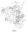
- FIG. 3 schematically depicts one example flow configuration of dual-stage pump assembly 16 adapted to receive fluid from gathering system 14. Some features have been omitted for purposes of clarity, including but not limited to housings 44, 46, 56, and 60 (seen in FIG. 2 ).
- Dual-stage pump assembly 16 can receive a fluid such as fuel (e.g., Jet A-1 or other suitable liquid fuel) through a number of feed lines 68.
- First and second gear pump stages 26, 28 include respective first and second inlet ports 70, 72 in fluid communication with fuel gathering system 14 (via one or more feed lines 68).
- Inlet ports 70, 72 lead incoming fluid to be pressurized by rotation of the corresponding sets of meshed gears (shown in FIGS. 4A-5B ).
- the meshed gears can be mounted to corresponding drive or driven shafts, which are in turn supported by first and second bearing assemblies 74,76.
- First and second flow attenuators 78, 80 are adapted so as to reduce eddy and turbulence in the incoming fluid, while reflecting, and thus cancelling remaining portions of the pressure ripple back to the gear pocket as the flow exits the respective pump stage (best seen in FIGS. 5A and 5B ).
- first and second flow attenuators 78, 80 each include substantially polygonal fluid openings 82, 84. Inlet side of polygonal fluid opening 82 and outlet side of polygonal opening 84 are obscured in FIG. 3 by bearing assemblies 74, 76. However, in this particular illustrative example, it will be understood that polygonal fluid openings 82, 84 on either side bearing assemblies 74, 76 can have four substantially right-angled walls or edges forming a rectangular or square flow boundary. As seen in FIGS. 4A and 4B , polygonal fluid opening 84 is of a similar shape as opening 82, as well as fluid outlet 86, which can also form a part of flow attenuator 80.
- Intersections of adjacent walls can form right angles, or can alternatively have one or more rounded corners to form polygonal fluid openings 82, 84.
- polygonal configurations other than substantially rectangular or square walls and edges are also appropriate depending on a particular flow pattern.
- edges of one or both polygonal fluid openings 52, 54 can be aligned with a corresponding undercut bearing portion to provide a non-round fluid boundary on an inlet side of the respective gear pump stage 26, 28.
- FIGS. 4A and 4B respectively show detailed views of first and second bearing assemblies 74, 76.
- Each of first and second bearing assemblies 74, 76 includes two stationary bearings and two floating bearings.
- a drive gear or driven gear, depending on the configuration, is mounted axially between a stationary bearing and a floating bearing.
- One pair of journal bearings can be stationary bearings, while the other pair can be pressure loaded floating bearings, capable of axial movement within their respective housings (shown in FIG. 2 ).
- first drive gear 86 is mounted to first drive shaft 95
- first driven gear 88 is mounted to first driven shaft 96.
- second driven gear 98 meshes with second drive gear 97 to define a second plurality of gear mesh pockets 99 between teeth 100A, 100B.
- first driven gear 88 (with gear teeth 89) meshes with first drive gear 86 (with gear teeth 87) to define a first plurality of gear mesh pockets 90.
- First bearing assembly 74 rotatably supports both first drive gear 86 and first driven gear 88 via floating journal bearings 91A, 91 B and stationary journal bearings 92A, 92B.
- FIG. 4A also shows an inlet portion of first attenuator 78, namely floating bearing undercuts 93A, 93B and stationary bearing undercuts 94A, 94B.
- These undercuts located proximate to a meshing location of gears 86, 88, generally align with the substantially polygonal shape of first fluid openings 82 (shown in FIG. 4A as a dashed line).
- Second bearing assembly 76 rotatably supports both second drive gear 97 and second driven gear 98 via second stationary journal bearings 101A, 101B and second floating journal bearings 102A, 102B.
- FIG. 4B also shows another inlet portion of second inlet attenuator 80, namely stationary bearing undercuts 104A, 104B and floating bearing undercuts 106A, 106B. These undercuts generally align with the substantially polygonal shape of second fluid openings 84 (shown in FIG. 4B as a dashed line). This is proximate to the meshing location of gears 97, 98.
- second drive gear 97 is mounted to second drive shaft 108
- second driven gear 98 is mounted to first driven shaft 110.
- edges of the respective polygonal fluid opening are aligned with the corresponding undercut bearing portion to provide a non-round fluid boundary on an inlet side of each respective gear pump stage.
- FIGS. 5A and 5B show a simulated flow path through one of the pump stages having an attenuator disposed proximate to the meshing location of the drive and driven gears.
- a confluence of inlet attenuator, the meshed gears, and the bearing walls define a corresponding first or second (i.e., servo or main) pump conduit with a non-round fluid boundary.
- Various flows Q through the conduit, as well as around the drive and driven gears, are represented by stippled surfaces.
- flow toward the inlet side of the attenuator is denoted as Q in and the pressurized flow around the outlet side of the attenuator is denoted Q out .
- Q in As fluid enters the attenuator, typically from round piping, Q in expands to the edges of the polygonal opening and becomes Q inlet . Some of this flow expands outwardly to counteract pulses from gear pocket flow (Q pocket ) converging from either side. At the same time, some of Q inlet flow, by way of the bearing undercuts is free to travel over or under mesh pockets 90/99. This flow Q undercut also destructively interferes with the converging and diverging fluid pulses of Q pocket as the fluid transitions to Q out and into high-pressure piping 110.
- the first and/or second pump conduit has a flow transition length equal to about an odd multiple of gear teeth. This reduces pressure ripple sufficiently to damp flow turbulence in the fuel system, leading to improved fuel metering, component life, and engine performance.
- a fuel system includes a fuel gathering system in fluid communication with a fuel storage container, and a fluid pump assembly in fluid communication with the fuel gathering system.
- the fluid pump assembly includes a main gear pump stage and a first flow attenuator.
- a main driven gear is meshed with a main drive gear in a main pump conduit, and a main pump bearing assembly rotatably supports the main drive gear and the main driven gear.
- the first flow attenuator is disposed around the main pump conduit, and includes a substantially polygonal fluid opening. Edges of the opening are substantially aligned with an undercut bearing portion on at least one of an inlet side and an outlet side of the main pump conduit to define a non-round fluid boundary.
- the fuel system of the preceding paragraph can optionally include, additionally and/or alternatively, any one or more of the following features, configurations and/or additional components:
- a fuel system includes a fuel storage container, a fuel gathering system in fluid communication with the fuel storage container, and a fluid pump assembly in fluid communication with the fuel gathering system, the fluid pump assembly including a main gear pump stage including a main driven gear meshed with a main drive gear in a main pump conduit, a main pump bearing assembly rotatably supporting the main drive gear and the main driven gear, and a first flow attenuator disposed around the main pump conduit, the first flow attenuator including a substantially polygonal fluid opening having edges substantially aligned with an undercut bearing portion on at least one of an inlet side and an outlet side of the main pump conduit to define a non-round fluid boundary.
- the fuel storage container comprises a plurality of wing-mounted fuel tanks.
- the fuel system further comprises a heat exchanger disposed upstream of the dual-stage fuel pump assembly, wherein the heat exchanger is in selective thermal communication with engine oil flowing through an engine thermal management system.
- the fluid pump assembly is a dual-stage fuel pump assembly and further comprises a servo gear pump stage including a servo driven gear meshed with a servo drive gear in a servo pump conduit, and a servo pump bearing assembly rotatably supporting the servo drive gear and the servo driven gear.
- the dual-stage fuel pump assembly further comprises: a second flow attenuator disposed around the main pump conduit, the second flow attenuator including a substantially polygonal fluid opening having edges substantially aligned with an undercut bearing portion on at least one of an inlet side and an outlet side of the servo pump conduit to define a non-round fluid boundary.
- the fuel system further comprises a gear shaft assembly rotatably connecting the servo drive gear and the main drive gear, wherein rotation of the gear shaft assembly simultaneously operates both the servo gear pump stage and the main gear pump stage.
- main pump conduit has a flow transition length equal to about an odd multiple of gear teeth.
- An embodiment of a fluid pump assembly includes a first gear pump stage, a second gear pump stage, a first pump bearing assembly, a second pump bearing assembly, a first flow attenuator, and a second flow attenuator.
- a first driven gear is meshed with a first drive gear in a first pump conduit, while a second driven gear is meshed with a second drive gear in a second pump conduit.
- the first pump bearing assembly rotatably supports the first drive gear and the first driven gear, while the second pump bearing assembly rotatably supports the second drive gear and the second driven gear.
- the first and second flow attenuators disposed around the first and second pump conduits, each include a pair of substantially polygonal fluid openings and a corresponding pair of undercut bearing portions disposed on at least one of an inlet side and an outlet side of the first and second pump conduits. Edges of the fluid openings have edges substantially aligned with the undercut bearing portions, defining first and second non-round fluid boundaries.
- the fluid pump assembly of the preceding paragraph can optionally include, additionally and/or alternatively, any one or more of the following features, configurations and/or additional components:
- a fluid pump assembly includes a first gear pump stage including a first driven gear meshed with a first drive gear in a first pump conduit; a second gear pump stage including a second driven gear meshed with a second drive gear in a second pump conduit; a first pump bearing assembly rotatably supporting the first drive gear and the first driven gear; a second pump bearing assembly rotatably supporting the second drive gear and the second driven gear; a first flow attenuator disposed around the first pump conduit, the first flow attenuator including a pair of substantially polygonal fluid openings having edges substantially aligned with a corresponding pair of undercut bearing portions disposed on at least one of an inlet side and an outlet side of the first pump conduit, and defining a first non-round fluid boundary; and a second flow attenuator disposed around the second pump conduit, the second flow attenuator including a pair of substantially polygonal fluid openings having edges substantially aligned with a corresponding pair of undercut bearing portions disposed
- the fluid pump assembly further comprises a gear shaft assembly rotatably connecting the first drive gear and the second drive gear.
- the first gear pump stage comprises a pump selected from a servo fuel pump and a main fuel pump; and the second gear pump stage comprises a pump selected from the other of the servo fuel pump and the main fuel pump.
- first drive gear is mounted to a first drive shaft; the first driven gear is mounted to a first drive shaft; the second drive gear is mounted to a second drive shaft; and the second driven gear is mounted to a second driven shaft.
- the first bearing assembly comprises: a first stationary journal bearing supporting a first axial end of the first drive shaft; a first pressure-loaded journal bearing supporting a second axial end of the first drive shaft; a second stationary journal bearing supporting a first axial end of the first driven shaft; and a second pressure-loaded journal bearing supporting a second axial end of the first driven shaft.
- a further embodiment of any of the foregoing fluid pump assemblies wherein additionally or alternatively, at least one of the first and second pump conduits has a flow transition length equal to about an odd multiple of gear teeth.
Landscapes
- Engineering & Computer Science (AREA)
- Mechanical Engineering (AREA)
- General Engineering & Computer Science (AREA)
- Chemical & Material Sciences (AREA)
- Combustion & Propulsion (AREA)
- Aviation & Aerospace Engineering (AREA)
- Rotary Pumps (AREA)
Abstract
Description
- This disclosure relates generally to fluid pumps, and more specifically to gear pumps for pressurizing a fluid.
- Though gear pumps are considered highly reliable, in some aircraft engine applications, incorrectly or inconsistently pressurized fuel or oil can seriously affect engine system performance and reduce component life. For example, fuel exiting a gear pump with high pressure ripple can cause cycling and hunting on the fuel metering valve, and if severe enough, pressure pulsation and cavitation can cause damage to the pump, piping or the engine itself.
- Rotary and reciprocating fluid pumps, depending on their design, can induce pressure waves, pulses, cavitation, and/or erosion damage both upstream and downstream of the pump. Fuel pump pressure ripple can be caused by the frequency of rotating device like a gear pump. The gear pump teeth provide cyclic flow with internal gear pockets rotating from the inlet port toward the discharge port. The continuous output of each of these pocket flow cycles produces what appears to be sequence flow output with an amplitude and frequency.
- An embodiment of a fuel system includes a fuel gathering system in fluid communication with a fuel storage container, and a fluid pump assembly in fluid communication with the fuel gathering system. The fluid pump assembly includes a main gear pump stage and a first flow attenuator. A main driven gear is meshed with a main drive gear in a main pump conduit, and a main pump bearing assembly rotatably supports the main drive gear and the main driven gear. The first flow attenuator is disposed around the main pump conduit, and includes a substantially polygonal fluid opening. Edges of the opening are substantially aligned with an undercut bearing portion on at least one of an inlet side and an outlet side of the main pump conduit to define a non-round fluid boundary.
- An embodiment of a fluid pump assembly includes a first gear pump stage, a second gear pump stage, a first pump bearing assembly, a second pump bearing assembly, a first flow attenuator, and a second flow attenuator. A first driven gear is meshed with a first drive gear in a first pump conduit, while a second driven gear is meshed with a second drive gear in a second pump conduit. The first pump bearing assembly rotatably supports the first drive gear and the first driven gear, while the second pump bearing assembly rotatably supports the second drive gear and the second driven gear. The first and second flow attenuators each include a pair of substantially polygonal fluid openings and a corresponding pair of undercut bearing portions disposed on at least one of an inlet side and an outlet side of the first and second pump conduits. The fluid openings have edges substantially aligned with the undercut bearing portions, defining first and second non-round fluid boundaries.
-
-
FIG. 1 is a block diagram showing a gas turbine fluid handling system including a dual-stage pump assembly. -
FIG. 2 schematically depicts an example dual-stage gear pump assembly and a corresponding flow configuration for the fluid handling system represented inFIG. 1 . -
FIG. 3 is a side view of an example dual-stage gear pump. -
FIG. 4A depicts a first stage of the dual-stage gear pump with undercut bearings disposed adjacent the gear mesh location. -
FIG. 4B depicts an undercut bearing configuration and gear mesh location for a second stage of the dual-stage gear pump. -
FIG. 5A is a first sectional view of flow through a first stage of the gear pump with undercut bearings disposed adjacent the gear mesh. -
FIG. 5B is a second sectional view of the dual-stage fuel pump and undercut bearings disposed adjacent the gear mesh. -
FIG. 1 is a schematic representation offluid handling system 10, which includes one or morefluid storage containers 12,fluid gathering system 14, and dual-stagefluid pump assembly 16. Generally,fluid gathering system 14 can include one or more pipes, boost pumps (e.g., low-pressure centrifugal boost pump 15), or other appurtenances in fluid communication with storage container(s) 12, while dual-stagefluid pump assembly 16 is in communication with, and can receive fluid fromgathering system 14. Though described with respect to certain illustrative embodiments, it will be appreciated thatfluid handling system 10 can be readily adapted (e.g., by adding, modifying, substituting, or omitting certain application-specific components) to other numerous applications including but not limited to gas turbine and/or transportation applications. -
Fluid handling system 10 is described with respect to an illustrative, nonlimiting embodiment of fuel system for one or more gas turbine engines installed on an aircraft. In this and other gas turbine applications, one or more heat exchangers 18 can also be incorporated intofuel system 10. In example embodiments for various aircraft, at least one of optional heat exchangers 18 can be a fuel-oil heat exchanger, while fluid storage container(s) 12 can include a plurality of wing-mounted fuel tanks. To preheat fuel prior to entering dual-stagefuel pump assembly 16 and (eventually)engine 20, heat exchanger 18 can be in selective thermal communication withengine oil 22 or other heated fluid flowing through an engine thermal management system (not shown). Though shown upstream of dual-stagefuel pump assembly 16, one or more heat exchangers 18 can additionally or alternatively be disposed downstream of dual-stagefuel pump assembly 16. - As seen in
FIG. 1 , dual-stagefuel pump assembly 16 includes firstgear pump stage 26 and secondgear pump stage 28. In certain applications such as aircraft fuel systems, first and secondgear pump stages gear pump stage 26 can include a pump selected from a servo fuel pump and a main fuel pump, while secondgear pump stage 28 can include a pump selected from the other of the servo fuel pump and the main fuel pump. Here, with reference to the illustrative example of an aircraft engine fuel system, firstgear pump stage 26 operates as a servo gear pump while secondgear pump stage 28 operates as a main gear pump. - Under moderate to high power demand, a portion of the incoming fuel from
fluid gathering system 14 can be diverted to firstgear pump stage 26 while a second portion (up to and possibly including the remainder) goes to secondgear pump stage 28. Fuel pressurized by firstgear pump stage 26 can be delivered primarily to serve as a hydraulic actuation fluid foractuators 24, operating various mechanical accessories in and aroundengine 20. Excess pressurized fuel from firstgear pump stage 26 can be merged with pressurized fuel from secondgear pump stage 28 via one or morepump sharing valves 30. Fuel from one or both stages can be cleaned (filter unit 31), and the combined pressurized fuel can then be metered (valve 32) and delivered viafuel nozzles 34 for combustion, providing primary motive power for engine(s) 20. Excess preheated and/or pressurizedfuel 36 can then be returned tofuel storage container 12 or otherwise recycled or reused to balance various system needs. - Dual-
stage pump assembly 16 includes features which reduce or mitigate a number of these issues, while still retaining the high reliability of gear pumps. At least one ofgear pump stages -
FIG. 2 shows an example view of one type of dual-stage gear-drivenfuel pump 16. As inFIG. 1 , first / servogear pump stage 26 and second / maingear pump stage 28 can be operated and driven in parallel by a single motor or motor unit. The motor unit can be any suitable electrically or mechanically operated device. Here, the motor can be a conventional single-phase or three-phase electrical motor with rotor portion 40 (accompanying stator omitted for clarity).Rotor portion 40 can be attached or connected to driveshaft 42, which is in turn rotatably connected to secondgear pump stage 28. One or more additional shafts can rotatably drive firstgear pump stage 26 via secondgear pump stage 28, or independently thereof. - Here, fluid to be pressurized by first gear pump stage 26 (e.g., liquid fuel) enters a set of meshed gears (shown in
FIG. 4A ) proximate to firstpump inlet location 44, but which are obscured by firstdrive side housing 46 and first drivenside housing 48. One or more first drive gears (shown inFIG. 4A ) are disposed in first drive side 50 (i.e., within first drive side housing 46). The first drive gears mesh with corresponding first driven gear(s) (also shown inFIG. 4A ) internal to first driven side 52 (i.e., within first driven side housing 48). -
FIG. 2 also shows secondgear pump stage 28 withsecond drive side 54 and second driven side 56. Internal to second drive side 54 (i.e., within second drive side housing 56), one or more drive gears (shown inFIG. 4B ) are rotatably coupled, either directly or indirectly, to driveshaft 42. The drive gear(s) are meshed with corresponding driven gear(s) (also shown inFIG. 4B ) internal to second drivenside 58. (i.e., within second driven side housing 60). Fluid to be pressurized by second gear pump stage 28 (here, also liquid fuel), enters the main set of meshed gears proximate mainpump inlet location 62. The actual inlet is obscured inFIG. 2 byhousings 56, 60. - In certain embodiments, first drive gear(s) can be rotatably coupled, directly or indirectly, to
coupling shaft 61. Maincoupling shaft assembly 61 can include one or more coupling shafts connected to internal drive shafts (not shown inFIG. 2 ), and can rotatably connect the first drive gear and/or drive shaft with the second drive gear and/or drive shaft so that rotation of maincoupling shaft assembly 61 allows simultaneously operation of both firstgear pump stage 26 and secondgear pump stage 28. - In certain embodiments, excess motive power from dual-
stage pump assembly 16 can also drive other accessories. In this example, fuel can first enter low-pressure port 64 disposed on firstgear pump stage 26, then enter low-pressure boost pump 15 (shown inFIG. 1 ), which can be driven bysupplemental shaft 66 rotatably coupled to second drivenside 48. -
FIG. 3 schematically depicts one example flow configuration of dual-stage pump assembly 16 adapted to receive fluid from gatheringsystem 14. Some features have been omitted for purposes of clarity, including but not limited tohousings FIG. 2 ). - Dual-
stage pump assembly 16 can receive a fluid such as fuel (e.g., Jet A-1 or other suitable liquid fuel) through a number of feed lines 68. First and second gear pump stages 26, 28 include respective first andsecond inlet ports Inlet ports FIGS. 4A-5B ). As best seen inFIGS. 4A and 4B , the meshed gears can be mounted to corresponding drive or driven shafts, which are in turn supported by first andsecond bearing assemblies - Conventional gear pumps, as well as certain other rotary or reciprocating pumps, induce a characteristic pressure profile in fluid exiting the pump. This pressure profile can be propagated as fluid moves throughout the system and can particularly affect the performance and/or life of sensitive downstream components. In gas turbine applications, a large effective amplitude of fluid pulses can cause fatigue and failure in downstream engine components receiving the pressurized fluid. At best, significant fluid pressure pulses or ripple from a conventional gear pump can result in imprecise fuel metering, as the fuel metering valves depend on a relatively constant feed pressure. In more pronounced cases, significant resonance of fluid pulses can rapidly damage fuel piping downstream of the gear pump. This pressure ripple (in frequency and/or amplitude) will cause engine performance loss and damage. And when a fluid pressurized by a conventional gear pump is to be used as a hydraulic actuation fluid, it can result in unnecessary vibration, noise, cavitation, and fatigue in the hydraulically actuated device(s).
- To help reduce or mitigate issues of fluid pulsing one or both gear pump stages 26, 28 can include first and
second flow attenuators second flow attenuators FIGS. 5A and 5B ). - In certain embodiments, first and
second flow attenuators polygonal fluid openings polygonal fluid opening 82 and outlet side ofpolygonal opening 84 are obscured inFIG. 3 by bearingassemblies fluid openings side bearing assemblies FIGS. 4A and 4B ,polygonal fluid opening 84 is of a similar shape as opening 82, as well asfluid outlet 86, which can also form a part offlow attenuator 80. Intersections of adjacent walls can form right angles, or can alternatively have one or more rounded corners to formpolygonal fluid openings FIGS. 4A-4B , edges of one or both polygonalfluid openings gear pump stage -
FIGS. 4A and 4B respectively show detailed views of first andsecond bearing assemblies second bearing assemblies FIG. 2 ). In this example,first drive gear 86 is mounted tofirst drive shaft 95, while first drivengear 88 is mounted to first drivenshaft 96. Similarly, inFIG. 4B , second drivengear 98 meshes withsecond drive gear 97 to define a second plurality of gear mesh pockets 99 betweenteeth - In
FIG. 4A , first driven gear 88 (with gear teeth 89) meshes with first drive gear 86 (with gear teeth 87) to define a first plurality of gear mesh pockets 90. First bearingassembly 74 rotatably supports bothfirst drive gear 86 and first drivengear 88 via floatingjournal bearings stationary journal bearings -
FIG. 4A also shows an inlet portion offirst attenuator 78, namely floating bearing undercuts 93A, 93B and stationary bearing undercuts 94A, 94B. These undercuts, located proximate to a meshing location ofgears FIG. 4A as a dashed line). -
Second bearing assembly 76 rotatably supports bothsecond drive gear 97 and second drivengear 98 via secondstationary journal bearings journal bearings FIG. 4B also shows another inlet portion ofsecond inlet attenuator 80, namely stationary bearing undercuts 104A, 104B and floating bearing undercuts 106A, 106B. These undercuts generally align with the substantially polygonal shape of second fluid openings 84 (shown inFIG. 4B as a dashed line). This is proximate to the meshing location ofgears second drive gear 97 is mounted tosecond drive shaft 108, while second drivengear 98 is mounted to first drivenshaft 110. - With respect to both
FIGS. 4A and 4B , edges of the respective polygonal fluid opening are aligned with the corresponding undercut bearing portion to provide a non-round fluid boundary on an inlet side of each respective gear pump stage. This is one such configuration of an attenuator which reduces and mitigates the effects of pressure ripple otherwise caused by conventional gear pumps. -
FIGS. 5A and 5B show a simulated flow path through one of the pump stages having an attenuator disposed proximate to the meshing location of the drive and driven gears. A confluence of inlet attenuator, the meshed gears, and the bearing walls define a corresponding first or second (i.e., servo or main) pump conduit with a non-round fluid boundary. Various flows Q through the conduit, as well as around the drive and driven gears, are represented by stippled surfaces. Here, flow toward the inlet side of the attenuator is denoted as Qin and the pressurized flow around the outlet side of the attenuator is denoted Qout. - As fluid enters the attenuator, typically from round piping, Qin expands to the edges of the polygonal opening and becomes Qinlet. Some of this flow expands outwardly to counteract pulses from gear pocket flow (Qpocket) converging from either side. At the same time, some of Qinlet flow, by way of the bearing undercuts is free to travel over or under mesh pockets 90/99. This flow Qundercut also destructively interferes with the converging and diverging fluid pulses of Qpocket as the fluid transitions to Qout and into high-
pressure piping 110. - In certain embodiments, the first and/or second pump conduit has a flow transition length equal to about an odd multiple of gear teeth. This reduces pressure ripple sufficiently to damp flow turbulence in the fuel system, leading to improved fuel metering, component life, and engine performance.
- The following are non-exclusive descriptions of possible embodiments of the present invention.
- A fuel system includes a fuel gathering system in fluid communication with a fuel storage container, and a fluid pump assembly in fluid communication with the fuel gathering system. The fluid pump assembly includes a main gear pump stage and a first flow attenuator. A main driven gear is meshed with a main drive gear in a main pump conduit, and a main pump bearing assembly rotatably supports the main drive gear and the main driven gear. The first flow attenuator is disposed around the main pump conduit, and includes a substantially polygonal fluid opening. Edges of the opening are substantially aligned with an undercut bearing portion on at least one of an inlet side and an outlet side of the main pump conduit to define a non-round fluid boundary.
- The fuel system of the preceding paragraph can optionally include, additionally and/or alternatively, any one or more of the following features, configurations and/or additional components:
- A fuel system according to an exemplary embodiment of this disclosure, among other possible things includes a fuel storage container, a fuel gathering system in fluid communication with the fuel storage container, and a fluid pump assembly in fluid communication with the fuel gathering system, the fluid pump assembly including a main gear pump stage including a main driven gear meshed with a main drive gear in a main pump conduit, a main pump bearing assembly rotatably supporting the main drive gear and the main driven gear, and a first flow attenuator disposed around the main pump conduit, the first flow attenuator including a substantially polygonal fluid opening having edges substantially aligned with an undercut bearing portion on at least one of an inlet side and an outlet side of the main pump conduit to define a non-round fluid boundary.
- A further embodiment of the foregoing fuel system, wherein additionally or alternatively, the fuel storage container comprises a plurality of wing-mounted fuel tanks.
- A further embodiment of any of the foregoing fuel systems, wherein additionally or alternatively, the fuel system further comprises a heat exchanger disposed upstream of the dual-stage fuel pump assembly, wherein the heat exchanger is in selective thermal communication with engine oil flowing through an engine thermal management system.
- A further embodiment of any of the foregoing fuel systems, wherein additionally or alternatively, the fluid pump assembly is a dual-stage fuel pump assembly and further comprises a servo gear pump stage including a servo driven gear meshed with a servo drive gear in a servo pump conduit, and a servo pump bearing assembly rotatably supporting the servo drive gear and the servo driven gear.
- A further embodiment of any of the foregoing fuel systems, wherein additionally or alternatively, the dual-stage fuel pump assembly further comprises: a second flow attenuator disposed around the main pump conduit, the second flow attenuator including a substantially polygonal fluid opening having edges substantially aligned with an undercut bearing portion on at least one of an inlet side and an outlet side of the servo pump conduit to define a non-round fluid boundary.
- A further embodiment of any of the foregoing fuel systems, wherein additionally or alternatively, the servo gear pump stage and the main gear pump stage are configured in parallel.
- A further embodiment of any of the foregoing fuel systems, wherein additionally or alternatively, the fuel system further comprises a gear shaft assembly rotatably connecting the servo drive gear and the main drive gear, wherein rotation of the gear shaft assembly simultaneously operates both the servo gear pump stage and the main gear pump stage.
- A further embodiment of any of the foregoing fuel systems, wherein additionally or alternatively, the main pump conduit has a flow transition length equal to about an odd multiple of gear teeth.
- An embodiment of a fluid pump assembly includes a first gear pump stage, a second gear pump stage, a first pump bearing assembly, a second pump bearing assembly, a first flow attenuator, and a second flow attenuator. A first driven gear is meshed with a first drive gear in a first pump conduit, while a second driven gear is meshed with a second drive gear in a second pump conduit. The first pump bearing assembly rotatably supports the first drive gear and the first driven gear, while the second pump bearing assembly rotatably supports the second drive gear and the second driven gear. The first and second flow attenuators, disposed around the first and second pump conduits, each include a pair of substantially polygonal fluid openings and a corresponding pair of undercut bearing portions disposed on at least one of an inlet side and an outlet side of the first and second pump conduits. Edges of the fluid openings have edges substantially aligned with the undercut bearing portions, defining first and second non-round fluid boundaries.
- The fluid pump assembly of the preceding paragraph can optionally include, additionally and/or alternatively, any one or more of the following features, configurations and/or additional components:
- A fluid pump assembly according to an exemplary embodiment of this disclosure, among other possible things includes a first gear pump stage including a first driven gear meshed with a first drive gear in a first pump conduit; a second gear pump stage including a second driven gear meshed with a second drive gear in a second pump conduit; a first pump bearing assembly rotatably supporting the first drive gear and the first driven gear; a second pump bearing assembly rotatably supporting the second drive gear and the second driven gear; a first flow attenuator disposed around the first pump conduit, the first flow attenuator including a pair of substantially polygonal fluid openings having edges substantially aligned with a corresponding pair of undercut bearing portions disposed on at least one of an inlet side and an outlet side of the first pump conduit, and defining a first non-round fluid boundary; and a second flow attenuator disposed around the second pump conduit, the second flow attenuator including a pair of substantially polygonal fluid openings having edges substantially aligned with a corresponding pair of undercut bearing portions disposed on at least one of an inlet side and an outlet side of the second pump conduit, and defining a second non-round fluid boundary.
- A further embodiment of the foregoing fluid pump assembly, wherein additionally or alternatively, the fluid pump assembly further comprises a gear shaft assembly rotatably connecting the first drive gear and the second drive gear.
- A further embodiment of any of the foregoing fluid pump assemblies, wherein additionally or alternatively, the first and second gear pump stages are configured in parallel.
- A further embodiment of any of the foregoing fluid pump assemblies, wherein additionally or alternatively, the first gear pump stage comprises a pump selected from a servo fuel pump and a main fuel pump; and the second gear pump stage comprises a pump selected from the other of the servo fuel pump and the main fuel pump.
- A further embodiment of any of the foregoing fluid pump assemblies, wherein additionally or alternatively, the first drive gear is mounted to a first drive shaft; the first driven gear is mounted to a first drive shaft; the second drive gear is mounted to a second drive shaft; and the second driven gear is mounted to a second driven shaft.
- A further embodiment of any of the foregoing fluid pump assemblies, wherein additionally or alternatively, the first bearing assembly comprises: a first stationary journal bearing supporting a first axial end of the first drive shaft; a first pressure-loaded journal bearing supporting a second axial end of the first drive shaft; a second stationary journal bearing supporting a first axial end of the first driven shaft; and a second pressure-loaded journal bearing supporting a second axial end of the first driven shaft.
- A further embodiment of any of the foregoing fluid pump assemblies, wherein additionally or alternatively, at least one of the first and second pump conduits has a flow transition length equal to about an odd multiple of gear teeth.
- While the invention has been described with reference to an exemplary embodiment(s), it will be understood by those skilled in the art that various changes may be made and equivalents may be substituted for elements thereof without departing from the scope of the invention. In addition, many modifications may be made to adapt a particular situation or material to the teachings of the invention without departing from the essential scope thereof. Therefore, it is intended that the invention not be limited to the particular embodiment(s) disclosed, but that the invention will include all embodiments falling within the scope of the appended claims.
Claims (15)
- A fuel system comprising:a fuel storage container;a fuel gathering system in fluid communication with the fuel storage container; anda fluid pump assembly in fluid communication with the fuel gathering system, the fluid pump assembly comprising:a main gear pump stage including a main driven gear meshed with a main drive gear in a main pump conduit, and a main pump bearing assembly rotatably supporting the main drive gear and the main driven gear; anda first flow attenuator disposed around the main pump conduit, the first flow attenuator including a substantially polygonal fluid opening having edges substantially aligned with an undercut bearing portion on at least one of an inlet side and an outlet side of the main pump conduit to define a non-round fluid boundary.
- The fuel system of claim 1, wherein the fuel storage container comprises:a plurality of wing-mounted fuel tanks.
- The fuel system of claim 1 or claim 2, further comprising:a heat exchanger disposed upstream of the dual-stage fuel pump assembly;wherein the heat exchanger is in selective thermal communication with engine oil flowing through an engine thermal management system.
- The fuel system of any preceding claim, wherein the fluid pump assembly is a dual-stage fuel pump assembly and further comprises:a servo gear pump stage including a servo driven gear meshed with a servo drive gear in a servo pump conduit, and a servo pump bearing assembly rotatably supporting the servo drive gear and the servo driven gear.
- The fuel system of any preceding claim, wherein the dual-stage fuel pump assembly further comprises:a second flow attenuator disposed around the main pump conduit, the second flow attenuator including a substantially polygonal fluid opening having edges substantially aligned with an undercut bearing portion on at least one of an inlet side and an outlet side of the servo pump conduit to define a non-round fluid boundary.
- The fuel system of claim 5, wherein the servo gear pump stage and the main gear pump stage are configured in parallel.
- The fuel system of claim 5, further comprising:a gear shaft assembly rotatably connecting the servo drive gear and the main drive gear;wherein rotation of the gear shaft assembly simultaneously operates both the servo gear pump stage and the main gear pump stage.
- The fuel system of any preceding claim, wherein the main pump conduit has a flow transition length equal to about an odd multiple of gear teeth.
- A fluid pump assembly comprising:a first gear pump stage including a first driven gear meshed with a first drive gear in a first pump conduit;a second gear pump stage including a second driven gear meshed with a second drive gear in a second pump conduit;a first pump bearing assembly rotatably supporting the first drive gear and the first driven gear;a second pump bearing assembly rotatably supporting the second drive gear and the second driven gear;a first flow attenuator disposed around the first pump conduit, the first flow attenuator including a pair of substantially polygonal fluid openings having edges substantially aligned with a corresponding pair of undercut bearing portions disposed on at least one of an inlet side and an outlet side of the first pump conduit, and defining a first non-round fluid boundary; anda second flow attenuator disposed around the second pump conduit, the second flow attenuator including a pair of substantially polygonal fluid openings having edges substantially aligned with a corresponding pair of undercut bearing portions disposed on at least one of an inlet side and an outlet side of the second pump conduit, and defining a second non-round fluid boundary.
- The fluid pump assembly of claim 9, further comprising:a gear shaft assembly rotatably connecting the first drive gear and the second drive gear.
- The fluid pump assembly of claim 9 or claim 10, wherein the first and second gear pump stages are configured in parallel.
- The fluid pump assembly of any of claims 9 to 11, wherein:the first gear pump stage comprises a pump selected from a servo fuel pump and a main fuel pump; andthe second gear pump stage comprises a pump selected from the other of the servo fuel pump and the main fuel pump.
- The fluid pump assembly of any of claims 9 to 12, wherein:the first drive gear is mounted to a first drive shaft;the first driven gear is mounted to a first drive shaft;the second drive gear is mounted to a second drive shaft; andthe second driven gear is mounted to a second driven shaft.
- The fluid pump assembly of claim 13, wherein the first bearing assembly comprises:a first stationary journal bearing supporting a first axial end of the first drive shaft;a first pressure-loaded journal bearing supporting a second axial end of the first drive shaft;a second stationary journal bearing supporting a first axial end of the first driven shaft; anda second pressure-loaded journal bearing supporting a second axial end of the first driven shaft.
- The fluid pump assembly of any of claims 9 to 14, wherein at least one of the first and second pump conduits has a flow transition length equal to about an odd multiple of gear teeth.
Applications Claiming Priority (1)
| Application Number | Priority Date | Filing Date | Title |
|---|---|---|---|
| US14/337,924 US9776728B2 (en) | 2014-07-22 | 2014-07-22 | Dual-stage gear pump with reduced pressure ripple |
Publications (3)
| Publication Number | Publication Date |
|---|---|
| EP2977591A1 true EP2977591A1 (en) | 2016-01-27 |
| EP2977591B1 EP2977591B1 (en) | 2022-03-30 |
| EP2977591B8 EP2977591B8 (en) | 2022-05-04 |
Family
ID=54007482
Family Applications (1)
| Application Number | Title | Priority Date | Filing Date |
|---|---|---|---|
| EP15177836.2A Active EP2977591B8 (en) | 2014-07-22 | 2015-07-22 | Dual-stage gear pump with reduced pressure ripple |
Country Status (2)
| Country | Link |
|---|---|
| US (1) | US9776728B2 (en) |
| EP (1) | EP2977591B8 (en) |
Cited By (1)
| Publication number | Priority date | Publication date | Assignee | Title |
|---|---|---|---|---|
| EP3219988A1 (en) * | 2016-03-16 | 2017-09-20 | Hamilton Sundstrand Corporation | Gear pump with passageways in gear teeth |
Families Citing this family (4)
| Publication number | Priority date | Publication date | Assignee | Title |
|---|---|---|---|---|
| US10428816B2 (en) * | 2016-10-24 | 2019-10-01 | Hamilton Sundstrand Corporation | Variable speed multi-stage pump |
| US10808695B2 (en) * | 2017-12-11 | 2020-10-20 | Hamilton Sundstrand Corporation | Reduction of cavitation in fuel pumps |
| RU185364U1 (en) * | 2018-06-08 | 2018-12-03 | Акционерное общество "Объединенная двигателестроительная корпорация" (АО "ОДК") | GEAR PUMP |
| US12209538B1 (en) * | 2023-09-11 | 2025-01-28 | Hamilton Sundstrand Corporation | Three pump fuel systems with selectable main and augmentor pumps |
Citations (2)
| Publication number | Priority date | Publication date | Assignee | Title |
|---|---|---|---|---|
| US20120219447A1 (en) * | 2011-02-25 | 2012-08-30 | Satish Shantilal Shah | Coupling shaft for gear pump |
| US20140023545A1 (en) * | 2012-07-23 | 2014-01-23 | Hamilton Sundstrand Corporation | Inlet cutbacks for high speed gear pump |
Family Cites Families (21)
| Publication number | Priority date | Publication date | Assignee | Title |
|---|---|---|---|---|
| US3981646A (en) | 1973-03-15 | 1976-09-21 | Lucas Aerospace Limited | Gear pumps and motors |
| GB1467441A (en) | 1973-03-15 | 1977-03-16 | Lucas Industries Ltd | Hydraulic gear pumps and motors |
| US4141673A (en) | 1975-05-19 | 1979-02-27 | Mccormick Eugene C | Engine dampener means |
| FR2535408A1 (en) | 1982-10-28 | 1984-05-04 | Snecma | DEVICE AND METHOD FOR DETECTING CUSTODY AT CAVITATION OF A VOLUMETRIC PUMP |
| US4505124A (en) * | 1983-09-22 | 1985-03-19 | The United States Of America As Represented By The Secretary Of The Air Force | Heat management system for aircraft |
| US4682938A (en) | 1985-12-26 | 1987-07-28 | Sundstrand Corporation | Gear pump bearings |
| US5118258A (en) | 1990-09-04 | 1992-06-02 | United Technologies Corporation | Dual pump fuel delivery system |
| US5863189A (en) | 1995-07-10 | 1999-01-26 | Coltec Industries Inc | Variable displacement vane pump adjustable by low actuation loads |
| US6123533A (en) | 1997-04-22 | 2000-09-26 | Dana Corporation | Cavitation-free gear pump |
| DE10239558B4 (en) | 2002-08-28 | 2005-03-17 | SCHWäBISCHE HüTTENWERKE GMBH | External gear pump with pressurized fluid precharge |
| GB0425785D0 (en) | 2004-11-24 | 2004-12-22 | Goodrich Control Sys Ltd | Fuel supply system |
| GB0509866D0 (en) | 2005-05-13 | 2005-06-22 | Goodrich Control Sys Ltd | Gear pump arrangement |
| US20070178003A1 (en) | 2005-11-22 | 2007-08-02 | Parker-Hannifin Corporation | Gear pump with ripple chamber for low noise and pressure ripples |
| US7591640B2 (en) | 2006-08-30 | 2009-09-22 | Ishikawajima-Harima Heavy Industries Co., Ltd. | Three gear type gear pump of a fuel supply system |
| FR2922264B1 (en) | 2007-10-12 | 2009-12-04 | Hispano Suiza Sa | FUEL SUPPLY CIRCUIT FOR AN AIRCRAFT ENGINE |
| US7878781B2 (en) | 2007-12-11 | 2011-02-01 | Hamilton Sundstrand Corporation | Gear pump cavitation reduction |
| US8137085B2 (en) | 2008-12-18 | 2012-03-20 | Hamilton Sundstrand Corporation | Gear pump with slots in teeth to reduce cavitation |
| US20100266437A1 (en) | 2009-04-16 | 2010-10-21 | Argo-Tech Corporation | Aircraft main engine fuel pump with multiple gear stages using shared journals |
| US9057372B2 (en) | 2010-12-06 | 2015-06-16 | Hamilton Sundstrand Corporation | Gear root geometry for increased carryover volume |
| US9677559B2 (en) * | 2011-02-25 | 2017-06-13 | Hamilton Sundstrand Corporation | Bearing face geometry for gear pump |
| US8944793B2 (en) | 2012-06-05 | 2015-02-03 | Hamilton Sundstrand Corporation | Flow and pressure ripple reduction with advance dual gear and bearing face cut |
-
2014
- 2014-07-22 US US14/337,924 patent/US9776728B2/en active Active
-
2015
- 2015-07-22 EP EP15177836.2A patent/EP2977591B8/en active Active
Patent Citations (2)
| Publication number | Priority date | Publication date | Assignee | Title |
|---|---|---|---|---|
| US20120219447A1 (en) * | 2011-02-25 | 2012-08-30 | Satish Shantilal Shah | Coupling shaft for gear pump |
| US20140023545A1 (en) * | 2012-07-23 | 2014-01-23 | Hamilton Sundstrand Corporation | Inlet cutbacks for high speed gear pump |
Cited By (2)
| Publication number | Priority date | Publication date | Assignee | Title |
|---|---|---|---|---|
| EP3219988A1 (en) * | 2016-03-16 | 2017-09-20 | Hamilton Sundstrand Corporation | Gear pump with passageways in gear teeth |
| US9945376B2 (en) | 2016-03-16 | 2018-04-17 | Hamilton Sundstrand Corporation | Gear pump |
Also Published As
| Publication number | Publication date |
|---|---|
| US9776728B2 (en) | 2017-10-03 |
| EP2977591B8 (en) | 2022-05-04 |
| EP2977591B1 (en) | 2022-03-30 |
| US20160023774A1 (en) | 2016-01-28 |
Similar Documents
| Publication | Publication Date | Title |
|---|---|---|
| EP2977591B1 (en) | Dual-stage gear pump with reduced pressure ripple | |
| EP3321488B1 (en) | Gas turbine engine accessories arrangement | |
| US11041443B2 (en) | Multi-spool gas turbine engine architecture | |
| US10690061B2 (en) | Gear train architecture for a multi-spool gas turbine engine | |
| EP3054128B1 (en) | Gearbox for gas turbine engine | |
| US10247102B2 (en) | Fuel/oil manifold | |
| EP3354876B1 (en) | Gas turbine engine architecture with split compressor system | |
| EP3597885B1 (en) | Gear train architecture for a multi-spool gas turbine engine | |
| EP1574688A1 (en) | Mechanical drive system for an accessory gearbox | |
| CN106285947B (en) | Pump for turbogenerator | |
| EP1574687A1 (en) | Mechanical drive system for an accessory gearbox | |
| JP2015166593A (en) | Direct weighing with variable displacement vane pump | |
| US11293308B2 (en) | Turbomachine lubrication unit and method of manufacture | |
| US9945376B2 (en) | Gear pump | |
| US20150337734A1 (en) | Variable geometries fluid supply circuit and injection system supply circuit | |
| EP2935829B1 (en) | Fuel system | |
| US11428164B2 (en) | Gas turbine engine with scalable pumping system | |
| US10273826B2 (en) | Lubrication device for a turbine engine | |
| EP3495662B1 (en) | Reduction of cavitation damages in fuel pumps |
Legal Events
| Date | Code | Title | Description |
|---|---|---|---|
| PUAI | Public reference made under article 153(3) epc to a published international application that has entered the european phase |
Free format text: ORIGINAL CODE: 0009012 |
|
| AK | Designated contracting states |
Kind code of ref document: A1 Designated state(s): AL AT BE BG CH CY CZ DE DK EE ES FI FR GB GR HR HU IE IS IT LI LT LU LV MC MK MT NL NO PL PT RO RS SE SI SK SM TR |
|
| AX | Request for extension of the european patent |
Extension state: BA ME |
|
| 17P | Request for examination filed |
Effective date: 20160721 |
|
| RBV | Designated contracting states (corrected) |
Designated state(s): AL AT BE BG CH CY CZ DE DK EE ES FI FR GB GR HR HU IE IS IT LI LT LU LV MC MK MT NL NO PL PT RO RS SE SI SK SM TR |
|
| STAA | Information on the status of an ep patent application or granted ep patent |
Free format text: STATUS: EXAMINATION IS IN PROGRESS |
|
| 17Q | First examination report despatched |
Effective date: 20200210 |
|
| GRAP | Despatch of communication of intention to grant a patent |
Free format text: ORIGINAL CODE: EPIDOSNIGR1 |
|
| STAA | Information on the status of an ep patent application or granted ep patent |
Free format text: STATUS: GRANT OF PATENT IS INTENDED |
|
| GRAJ | Information related to disapproval of communication of intention to grant by the applicant or resumption of examination proceedings by the epo deleted |
Free format text: ORIGINAL CODE: EPIDOSDIGR1 |
|
| STAA | Information on the status of an ep patent application or granted ep patent |
Free format text: STATUS: EXAMINATION IS IN PROGRESS |
|
| GRAP | Despatch of communication of intention to grant a patent |
Free format text: ORIGINAL CODE: EPIDOSNIGR1 |
|
| STAA | Information on the status of an ep patent application or granted ep patent |
Free format text: STATUS: GRANT OF PATENT IS INTENDED |
|
| INTG | Intention to grant announced |
Effective date: 20211012 |
|
| INTC | Intention to grant announced (deleted) | ||
| INTG | Intention to grant announced |
Effective date: 20211026 |
|
| GRAS | Grant fee paid |
Free format text: ORIGINAL CODE: EPIDOSNIGR3 |
|
| GRAA | (expected) grant |
Free format text: ORIGINAL CODE: 0009210 |
|
| STAA | Information on the status of an ep patent application or granted ep patent |
Free format text: STATUS: THE PATENT HAS BEEN GRANTED |
|
| REG | Reference to a national code |
Ref country code: DE Ref legal event code: R081 Ref document number: 602015077814 Country of ref document: DE Owner name: HAMILTON SUNDSTRAND CORPORATION, CHARLOTTE, US Free format text: FORMER OWNER: HAMILTON SUNDSTRAND CORPORATION, WINDSOR LOCKS, CT, US |
|
| AK | Designated contracting states |
Kind code of ref document: B1 Designated state(s): AL AT BE BG CH CY CZ DE DK EE ES FI FR GB GR HR HU IE IS IT LI LT LU LV MC MK MT NL NO PL PT RO RS SE SI SK SM TR |
|
| REG | Reference to a national code |
Ref country code: GB Ref legal event code: FG4D |
|
| REG | Reference to a national code |
Ref country code: CH Ref legal event code: EP |
|
| RAP4 | Party data changed (patent owner data changed or rights of a patent transferred) |
Owner name: HAMILTON SUNDSTRAND CORPORATION |
|
| REG | Reference to a national code |
Ref country code: CH Ref legal event code: PK Free format text: BERICHTIGUNG B8 Ref country code: DE Ref legal event code: R096 Ref document number: 602015077814 Country of ref document: DE |
|
| REG | Reference to a national code |
Ref country code: AT Ref legal event code: REF Ref document number: 1479400 Country of ref document: AT Kind code of ref document: T Effective date: 20220415 |
|
| REG | Reference to a national code |
Ref country code: IE Ref legal event code: FG4D |
|
| REG | Reference to a national code |
Ref country code: LT Ref legal event code: MG9D |
|
| PG25 | Lapsed in a contracting state [announced via postgrant information from national office to epo] |
Ref country code: SE Free format text: LAPSE BECAUSE OF FAILURE TO SUBMIT A TRANSLATION OF THE DESCRIPTION OR TO PAY THE FEE WITHIN THE PRESCRIBED TIME-LIMIT Effective date: 20220330 Ref country code: RS Free format text: LAPSE BECAUSE OF FAILURE TO SUBMIT A TRANSLATION OF THE DESCRIPTION OR TO PAY THE FEE WITHIN THE PRESCRIBED TIME-LIMIT Effective date: 20220330 Ref country code: NO Free format text: LAPSE BECAUSE OF FAILURE TO SUBMIT A TRANSLATION OF THE DESCRIPTION OR TO PAY THE FEE WITHIN THE PRESCRIBED TIME-LIMIT Effective date: 20220630 Ref country code: LT Free format text: LAPSE BECAUSE OF FAILURE TO SUBMIT A TRANSLATION OF THE DESCRIPTION OR TO PAY THE FEE WITHIN THE PRESCRIBED TIME-LIMIT Effective date: 20220330 Ref country code: HR Free format text: LAPSE BECAUSE OF FAILURE TO SUBMIT A TRANSLATION OF THE DESCRIPTION OR TO PAY THE FEE WITHIN THE PRESCRIBED TIME-LIMIT Effective date: 20220330 Ref country code: BG Free format text: LAPSE BECAUSE OF FAILURE TO SUBMIT A TRANSLATION OF THE DESCRIPTION OR TO PAY THE FEE WITHIN THE PRESCRIBED TIME-LIMIT Effective date: 20220630 |
|
| REG | Reference to a national code |
Ref country code: NL Ref legal event code: MP Effective date: 20220330 |
|
| REG | Reference to a national code |
Ref country code: AT Ref legal event code: MK05 Ref document number: 1479400 Country of ref document: AT Kind code of ref document: T Effective date: 20220330 |
|
| PG25 | Lapsed in a contracting state [announced via postgrant information from national office to epo] |
Ref country code: LV Free format text: LAPSE BECAUSE OF FAILURE TO SUBMIT A TRANSLATION OF THE DESCRIPTION OR TO PAY THE FEE WITHIN THE PRESCRIBED TIME-LIMIT Effective date: 20220330 Ref country code: GR Free format text: LAPSE BECAUSE OF FAILURE TO SUBMIT A TRANSLATION OF THE DESCRIPTION OR TO PAY THE FEE WITHIN THE PRESCRIBED TIME-LIMIT Effective date: 20220701 Ref country code: FI Free format text: LAPSE BECAUSE OF FAILURE TO SUBMIT A TRANSLATION OF THE DESCRIPTION OR TO PAY THE FEE WITHIN THE PRESCRIBED TIME-LIMIT Effective date: 20220330 |
|
| PG25 | Lapsed in a contracting state [announced via postgrant information from national office to epo] |
Ref country code: NL Free format text: LAPSE BECAUSE OF FAILURE TO SUBMIT A TRANSLATION OF THE DESCRIPTION OR TO PAY THE FEE WITHIN THE PRESCRIBED TIME-LIMIT Effective date: 20220330 |
|
| PG25 | Lapsed in a contracting state [announced via postgrant information from national office to epo] |
Ref country code: SM Free format text: LAPSE BECAUSE OF FAILURE TO SUBMIT A TRANSLATION OF THE DESCRIPTION OR TO PAY THE FEE WITHIN THE PRESCRIBED TIME-LIMIT Effective date: 20220330 Ref country code: SK Free format text: LAPSE BECAUSE OF FAILURE TO SUBMIT A TRANSLATION OF THE DESCRIPTION OR TO PAY THE FEE WITHIN THE PRESCRIBED TIME-LIMIT Effective date: 20220330 Ref country code: RO Free format text: LAPSE BECAUSE OF FAILURE TO SUBMIT A TRANSLATION OF THE DESCRIPTION OR TO PAY THE FEE WITHIN THE PRESCRIBED TIME-LIMIT Effective date: 20220330 Ref country code: PT Free format text: LAPSE BECAUSE OF FAILURE TO SUBMIT A TRANSLATION OF THE DESCRIPTION OR TO PAY THE FEE WITHIN THE PRESCRIBED TIME-LIMIT Effective date: 20220801 Ref country code: ES Free format text: LAPSE BECAUSE OF FAILURE TO SUBMIT A TRANSLATION OF THE DESCRIPTION OR TO PAY THE FEE WITHIN THE PRESCRIBED TIME-LIMIT Effective date: 20220330 Ref country code: EE Free format text: LAPSE BECAUSE OF FAILURE TO SUBMIT A TRANSLATION OF THE DESCRIPTION OR TO PAY THE FEE WITHIN THE PRESCRIBED TIME-LIMIT Effective date: 20220330 Ref country code: CZ Free format text: LAPSE BECAUSE OF FAILURE TO SUBMIT A TRANSLATION OF THE DESCRIPTION OR TO PAY THE FEE WITHIN THE PRESCRIBED TIME-LIMIT Effective date: 20220330 Ref country code: AT Free format text: LAPSE BECAUSE OF FAILURE TO SUBMIT A TRANSLATION OF THE DESCRIPTION OR TO PAY THE FEE WITHIN THE PRESCRIBED TIME-LIMIT Effective date: 20220330 |
|
| PG25 | Lapsed in a contracting state [announced via postgrant information from national office to epo] |
Ref country code: PL Free format text: LAPSE BECAUSE OF FAILURE TO SUBMIT A TRANSLATION OF THE DESCRIPTION OR TO PAY THE FEE WITHIN THE PRESCRIBED TIME-LIMIT Effective date: 20220330 Ref country code: IS Free format text: LAPSE BECAUSE OF FAILURE TO SUBMIT A TRANSLATION OF THE DESCRIPTION OR TO PAY THE FEE WITHIN THE PRESCRIBED TIME-LIMIT Effective date: 20220730 Ref country code: AL Free format text: LAPSE BECAUSE OF FAILURE TO SUBMIT A TRANSLATION OF THE DESCRIPTION OR TO PAY THE FEE WITHIN THE PRESCRIBED TIME-LIMIT Effective date: 20220330 |
|
| REG | Reference to a national code |
Ref country code: DE Ref legal event code: R097 Ref document number: 602015077814 Country of ref document: DE |
|
| PG25 | Lapsed in a contracting state [announced via postgrant information from national office to epo] |
Ref country code: DK Free format text: LAPSE BECAUSE OF FAILURE TO SUBMIT A TRANSLATION OF THE DESCRIPTION OR TO PAY THE FEE WITHIN THE PRESCRIBED TIME-LIMIT Effective date: 20220330 |
|
| PLBE | No opposition filed within time limit |
Free format text: ORIGINAL CODE: 0009261 |
|
| STAA | Information on the status of an ep patent application or granted ep patent |
Free format text: STATUS: NO OPPOSITION FILED WITHIN TIME LIMIT |
|
| PG25 | Lapsed in a contracting state [announced via postgrant information from national office to epo] |
Ref country code: MC Free format text: LAPSE BECAUSE OF FAILURE TO SUBMIT A TRANSLATION OF THE DESCRIPTION OR TO PAY THE FEE WITHIN THE PRESCRIBED TIME-LIMIT Effective date: 20220330 |
|
| REG | Reference to a national code |
Ref country code: CH Ref legal event code: PL |
|
| 26N | No opposition filed |
Effective date: 20230103 |
|
| REG | Reference to a national code |
Ref country code: BE Ref legal event code: MM Effective date: 20220731 |
|
| PG25 | Lapsed in a contracting state [announced via postgrant information from national office to epo] |
Ref country code: LU Free format text: LAPSE BECAUSE OF NON-PAYMENT OF DUE FEES Effective date: 20220722 Ref country code: LI Free format text: LAPSE BECAUSE OF NON-PAYMENT OF DUE FEES Effective date: 20220731 Ref country code: CH Free format text: LAPSE BECAUSE OF NON-PAYMENT OF DUE FEES Effective date: 20220731 |
|
| PG25 | Lapsed in a contracting state [announced via postgrant information from national office to epo] |
Ref country code: SI Free format text: LAPSE BECAUSE OF FAILURE TO SUBMIT A TRANSLATION OF THE DESCRIPTION OR TO PAY THE FEE WITHIN THE PRESCRIBED TIME-LIMIT Effective date: 20220330 Ref country code: BE Free format text: LAPSE BECAUSE OF NON-PAYMENT OF DUE FEES Effective date: 20220731 |
|
| P01 | Opt-out of the competence of the unified patent court (upc) registered |
Effective date: 20230522 |
|
| PG25 | Lapsed in a contracting state [announced via postgrant information from national office to epo] |
Ref country code: IT Free format text: LAPSE BECAUSE OF FAILURE TO SUBMIT A TRANSLATION OF THE DESCRIPTION OR TO PAY THE FEE WITHIN THE PRESCRIBED TIME-LIMIT Effective date: 20220330 Ref country code: IE Free format text: LAPSE BECAUSE OF NON-PAYMENT OF DUE FEES Effective date: 20220722 |
|
| PG25 | Lapsed in a contracting state [announced via postgrant information from national office to epo] |
Ref country code: HU Free format text: LAPSE BECAUSE OF FAILURE TO SUBMIT A TRANSLATION OF THE DESCRIPTION OR TO PAY THE FEE WITHIN THE PRESCRIBED TIME-LIMIT; INVALID AB INITIO Effective date: 20150722 |
|
| PG25 | Lapsed in a contracting state [announced via postgrant information from national office to epo] |
Ref country code: MK Free format text: LAPSE BECAUSE OF FAILURE TO SUBMIT A TRANSLATION OF THE DESCRIPTION OR TO PAY THE FEE WITHIN THE PRESCRIBED TIME-LIMIT Effective date: 20220330 Ref country code: CY Free format text: LAPSE BECAUSE OF FAILURE TO SUBMIT A TRANSLATION OF THE DESCRIPTION OR TO PAY THE FEE WITHIN THE PRESCRIBED TIME-LIMIT Effective date: 20220330 |
|
| PG25 | Lapsed in a contracting state [announced via postgrant information from national office to epo] |
Ref country code: MT Free format text: LAPSE BECAUSE OF FAILURE TO SUBMIT A TRANSLATION OF THE DESCRIPTION OR TO PAY THE FEE WITHIN THE PRESCRIBED TIME-LIMIT Effective date: 20220330 |
|
| PGFP | Annual fee paid to national office [announced via postgrant information from national office to epo] |
Ref country code: GB Payment date: 20250619 Year of fee payment: 11 |
|
| PGFP | Annual fee paid to national office [announced via postgrant information from national office to epo] |
Ref country code: FR Payment date: 20250620 Year of fee payment: 11 |
|
| PGFP | Annual fee paid to national office [announced via postgrant information from national office to epo] |
Ref country code: DE Payment date: 20250620 Year of fee payment: 11 |
|
| PG25 | Lapsed in a contracting state [announced via postgrant information from national office to epo] |
Ref country code: TR Free format text: LAPSE BECAUSE OF FAILURE TO SUBMIT A TRANSLATION OF THE DESCRIPTION OR TO PAY THE FEE WITHIN THE PRESCRIBED TIME-LIMIT Effective date: 20220330 |