EP2977566A1 - Pressure controlled chamber - Google Patents
Pressure controlled chamber Download PDFInfo
- Publication number
- EP2977566A1 EP2977566A1 EP15176769.6A EP15176769A EP2977566A1 EP 2977566 A1 EP2977566 A1 EP 2977566A1 EP 15176769 A EP15176769 A EP 15176769A EP 2977566 A1 EP2977566 A1 EP 2977566A1
- Authority
- EP
- European Patent Office
- Prior art keywords
- chamber
- pressure
- flow
- vent
- fluid flow
- Prior art date
- Legal status (The legal status is an assumption and is not a legal conclusion. Google has not performed a legal analysis and makes no representation as to the accuracy of the status listed.)
- Withdrawn
Links
Images

Classifications
-
- F—MECHANICAL ENGINEERING; LIGHTING; HEATING; WEAPONS; BLASTING
- F17—STORING OR DISTRIBUTING GASES OR LIQUIDS
- F17C—VESSELS FOR CONTAINING OR STORING COMPRESSED, LIQUEFIED OR SOLIDIFIED GASES; FIXED-CAPACITY GAS-HOLDERS; FILLING VESSELS WITH, OR DISCHARGING FROM VESSELS, COMPRESSED, LIQUEFIED, OR SOLIDIFIED GASES
- F17C13/00—Details of vessels or of the filling or discharging of vessels
- F17C13/002—Details of vessels or of the filling or discharging of vessels for vessels under pressure
-
- F—MECHANICAL ENGINEERING; LIGHTING; HEATING; WEAPONS; BLASTING
- F01—MACHINES OR ENGINES IN GENERAL; ENGINE PLANTS IN GENERAL; STEAM ENGINES
- F01D—NON-POSITIVE DISPLACEMENT MACHINES OR ENGINES, e.g. STEAM TURBINES
- F01D25/00—Component parts, details, or accessories, not provided for in, or of interest apart from, other groups
- F01D25/16—Arrangement of bearings; Supporting or mounting bearings in casings
- F01D25/162—Bearing supports
-
- F—MECHANICAL ENGINEERING; LIGHTING; HEATING; WEAPONS; BLASTING
- F01—MACHINES OR ENGINES IN GENERAL; ENGINE PLANTS IN GENERAL; STEAM ENGINES
- F01D—NON-POSITIVE DISPLACEMENT MACHINES OR ENGINES, e.g. STEAM TURBINES
- F01D25/00—Component parts, details, or accessories, not provided for in, or of interest apart from, other groups
- F01D25/16—Arrangement of bearings; Supporting or mounting bearings in casings
-
- F—MECHANICAL ENGINEERING; LIGHTING; HEATING; WEAPONS; BLASTING
- F01—MACHINES OR ENGINES IN GENERAL; ENGINE PLANTS IN GENERAL; STEAM ENGINES
- F01D—NON-POSITIVE DISPLACEMENT MACHINES OR ENGINES, e.g. STEAM TURBINES
- F01D25/00—Component parts, details, or accessories, not provided for in, or of interest apart from, other groups
- F01D25/18—Lubricating arrangements
-
- F—MECHANICAL ENGINEERING; LIGHTING; HEATING; WEAPONS; BLASTING
- F01—MACHINES OR ENGINES IN GENERAL; ENGINE PLANTS IN GENERAL; STEAM ENGINES
- F01D—NON-POSITIVE DISPLACEMENT MACHINES OR ENGINES, e.g. STEAM TURBINES
- F01D25/00—Component parts, details, or accessories, not provided for in, or of interest apart from, other groups
- F01D25/18—Lubricating arrangements
- F01D25/183—Sealing means
-
- F—MECHANICAL ENGINEERING; LIGHTING; HEATING; WEAPONS; BLASTING
- F02—COMBUSTION ENGINES; HOT-GAS OR COMBUSTION-PRODUCT ENGINE PLANTS
- F02C—GAS-TURBINE PLANTS; AIR INTAKES FOR JET-PROPULSION PLANTS; CONTROLLING FUEL SUPPLY IN AIR-BREATHING JET-PROPULSION PLANTS
- F02C7/00—Features, components parts, details or accessories, not provided for in, or of interest apart form groups F02C1/00 - F02C6/00; Air intakes for jet-propulsion plants
- F02C7/06—Arrangements of bearings; Lubricating
-
- F—MECHANICAL ENGINEERING; LIGHTING; HEATING; WEAPONS; BLASTING
- F05—INDEXING SCHEMES RELATING TO ENGINES OR PUMPS IN VARIOUS SUBCLASSES OF CLASSES F01-F04
- F05D—INDEXING SCHEME FOR ASPECTS RELATING TO NON-POSITIVE-DISPLACEMENT MACHINES OR ENGINES, GAS-TURBINES OR JET-PROPULSION PLANTS
- F05D2220/00—Application
- F05D2220/30—Application in turbines
- F05D2220/32—Application in turbines in gas turbines
-
- F—MECHANICAL ENGINEERING; LIGHTING; HEATING; WEAPONS; BLASTING
- F05—INDEXING SCHEMES RELATING TO ENGINES OR PUMPS IN VARIOUS SUBCLASSES OF CLASSES F01-F04
- F05D—INDEXING SCHEME FOR ASPECTS RELATING TO NON-POSITIVE-DISPLACEMENT MACHINES OR ENGINES, GAS-TURBINES OR JET-PROPULSION PLANTS
- F05D2240/00—Components
- F05D2240/50—Bearings
-
- F—MECHANICAL ENGINEERING; LIGHTING; HEATING; WEAPONS; BLASTING
- F05—INDEXING SCHEMES RELATING TO ENGINES OR PUMPS IN VARIOUS SUBCLASSES OF CLASSES F01-F04
- F05D—INDEXING SCHEME FOR ASPECTS RELATING TO NON-POSITIVE-DISPLACEMENT MACHINES OR ENGINES, GAS-TURBINES OR JET-PROPULSION PLANTS
- F05D2240/00—Components
- F05D2240/55—Seals
-
- F—MECHANICAL ENGINEERING; LIGHTING; HEATING; WEAPONS; BLASTING
- F05—INDEXING SCHEMES RELATING TO ENGINES OR PUMPS IN VARIOUS SUBCLASSES OF CLASSES F01-F04
- F05D—INDEXING SCHEME FOR ASPECTS RELATING TO NON-POSITIVE-DISPLACEMENT MACHINES OR ENGINES, GAS-TURBINES OR JET-PROPULSION PLANTS
- F05D2260/00—Function
- F05D2260/60—Fluid transfer
- F05D2260/605—Venting into the ambient atmosphere or the like
-
- F—MECHANICAL ENGINEERING; LIGHTING; HEATING; WEAPONS; BLASTING
- F05—INDEXING SCHEMES RELATING TO ENGINES OR PUMPS IN VARIOUS SUBCLASSES OF CLASSES F01-F04
- F05D—INDEXING SCHEME FOR ASPECTS RELATING TO NON-POSITIVE-DISPLACEMENT MACHINES OR ENGINES, GAS-TURBINES OR JET-PROPULSION PLANTS
- F05D2260/00—Function
- F05D2260/98—Lubrication
-
- F—MECHANICAL ENGINEERING; LIGHTING; HEATING; WEAPONS; BLASTING
- F05—INDEXING SCHEMES RELATING TO ENGINES OR PUMPS IN VARIOUS SUBCLASSES OF CLASSES F01-F04
- F05D—INDEXING SCHEME FOR ASPECTS RELATING TO NON-POSITIVE-DISPLACEMENT MACHINES OR ENGINES, GAS-TURBINES OR JET-PROPULSION PLANTS
- F05D2270/00—Control
- F05D2270/30—Control parameters, e.g. input parameters
- F05D2270/301—Pressure
- F05D2270/3015—Pressure differential pressure
-
- F—MECHANICAL ENGINEERING; LIGHTING; HEATING; WEAPONS; BLASTING
- F05—INDEXING SCHEMES RELATING TO ENGINES OR PUMPS IN VARIOUS SUBCLASSES OF CLASSES F01-F04
- F05D—INDEXING SCHEME FOR ASPECTS RELATING TO NON-POSITIVE-DISPLACEMENT MACHINES OR ENGINES, GAS-TURBINES OR JET-PROPULSION PLANTS
- F05D2270/00—Control
- F05D2270/40—Type of control system
- F05D2270/42—Type of control system passive or reactive, e.g. using large wind vanes
-
- F—MECHANICAL ENGINEERING; LIGHTING; HEATING; WEAPONS; BLASTING
- F16—ENGINEERING ELEMENTS AND UNITS; GENERAL MEASURES FOR PRODUCING AND MAINTAINING EFFECTIVE FUNCTIONING OF MACHINES OR INSTALLATIONS; THERMAL INSULATION IN GENERAL
- F16C—SHAFTS; FLEXIBLE SHAFTS; ELEMENTS OR CRANKSHAFT MECHANISMS; ROTARY BODIES OTHER THAN GEARING ELEMENTS; BEARINGS
- F16C2360/00—Engines or pumps
- F16C2360/23—Gas turbine engines
-
- F—MECHANICAL ENGINEERING; LIGHTING; HEATING; WEAPONS; BLASTING
- F16—ENGINEERING ELEMENTS AND UNITS; GENERAL MEASURES FOR PRODUCING AND MAINTAINING EFFECTIVE FUNCTIONING OF MACHINES OR INSTALLATIONS; THERMAL INSULATION IN GENERAL
- F16C—SHAFTS; FLEXIBLE SHAFTS; ELEMENTS OR CRANKSHAFT MECHANISMS; ROTARY BODIES OTHER THAN GEARING ELEMENTS; BEARINGS
- F16C33/00—Parts of bearings; Special methods for making bearings or parts thereof
- F16C33/72—Sealings
- F16C33/726—Sealings with means to vent the interior of the bearing
Definitions
- the present disclosure concerns pressure controlled chamber arrangements, methods of controlling fluid removal from pressure controlled chamber arrangements and gas turbine engines.
- the invention may have particular utility in controlling vent flow from the bearing chambers of gas turbine engines.
- the background section introduces the disclosure in the context of bearing chamber vent flow control. Despite this the invention is not limited to such uses and could for example be used in the context of clean rooms or hazardous material storage.
- Gas turbine engines comprise one or more rotating shafts, for which support from one or more bearings is required. These bearings are lubricated by oil, which is pumped into and out of bearing chambers in a closed circuit, the bearing chambers surrounding the bearings. In order to limit the risk of oil fires and cabin fume issues, it is desirable to prevent leakage of oil from the circuit. A potential source of oil escape is the rotating to static interface between the shaft and bearing chamber.
- seals are used to limit oil escape, but as seals are not completely leakproof it is normal to ensure that the pressure outside the bearing chamber is higher than the pressure within the bearing chamber. In this way air leaks into the chamber through the seals, preventing oil escape.
- the pressure differential is created by a vent system.
- the vent system draws air from inside the bearing chamber via a vent line, thereby creating a pressure differential that tends to cause fluid leakage across the seals from the outside to the inside of the bearing chamber.
- the vent air drawn from the bearing chamber is exhausted overboard via various air/oil separation devices.
- a vent restrictor is typically used to control the amount of airflow drawn through the vent line, the vent restrictor typically being a fixed capacity orifice plate or venturi that is sized to give the maximum airflow that might be required regardless of engine operating point.
- the sealing performance is sufficiently high, i.e. where the leakage capacity through the seals is significantly less than the capacity of the vent line, the bearing chamber pressure will reach that of the vent line. In this case the pressure differential created across the seals may cause them to fail. This may lead to inefficient quantities of sealing air consumption and/or oil leakage.
- a pressure controlled chamber arrangement optionally comprising a chamber, optionally one or more seals optionally arranged in use to limit fluid flow between the inside and outside of the chamber and optionally a vent system arranged in use to remove a vent flow of fluid from the inside of the chamber and optionally at least contribute to the formation of a pressure drop across the one or more seals from the outside to the inside of the chamber, the vent system optionally comprising a flow controller optionally arranged in use to control the quantity of fluid removal via the vent system optionally in accordance with the sealing performance provided by the one or more seals, the vent system optionally giving increased quantity of fluid removal for decreased sealing performance.
- a change in sealing performance might for example be indicated by a change in the pressure differential between the inside and outside of the chamber; all else being equal, a drop in pressure differential indicating a deterioration in sealing performance.
- Controlling the quantity of fluid removal in accordance with the sealing performance provided by the one or more seals may increase seal life and/or reduce the likelihood of seal failure. Protecting the seals in this way may in turn reduce the likelihood of leakage across the seals from the inside to the outside of the chamber. In the event of a seal failure the normal operation of the flow controller (i.e. increasing fluid removal in the event of sealing performance reduction) may be an appropriate response. Further the selecting of the quantity of fluid removal in accordance with sealing performance may increase efficiency, the fluid quantity removed from the chamber being substantially the minimum required in order to produce the necessary degree of sealing.
- the flow controller biases the apparatus towards an equilibrium condition where the pressure ratio across the seals is substantially consistent regardless of the sealing performance.
- the flow controller returns the apparatus to an equilibrium condition by recovering the pressure ratio across the seals.
- the flow controller uses a control fluid flow to control the quantity of fluid removal via the vent system.
- the control fluid flow may be delivered via a control line in fluid communication with a source of pressurised fluid.
- the flow controller is arranged such that an increase in vent flow pressure relative to control fluid flow pressure results in an increase in the quantity of fluid removal.
- control fluid flow is taken from a source giving a control fluid flow pressure with a known relationship to the pressure around the seals external to the chamber. If the control fluid flow pressure is related to the pressure around the seals external to the chamber, it may be that the control fluid flow can be managed more easily to give passive control over the pressure differential across the seals. The pressure around the seals external to the chamber is a factor in determining the pressure differential across the seals. Because the control fluid flow pressure is related to the pressure on one side of the seals, it may therefore be more useful for use in directly controlling the quantity of fluid removed from the chamber to control the pressure differential.
- the flow controller uses the control fluid flow to automatically give rise to a predictable alteration in the quantity of fluid removed from the chamber. Passive control may be desirable, as it may allow for a reduction in component count and improve reliability.
- control fluid flow is taken from a source giving a control fluid flow pressure proportional to the pressure around the seals external to the chamber. If the control fluid flow pressure is proportional to the pressure around the seals external to the chamber, the quantity of management required in order for the control fluid flow to facilitate passive control over the quantity of fluid removed may be reduced. Specifically an increase in sealing performance would give rise to a relative drop in the pressure of the vent flow with respect to the control fluid flow pressure. Similarly a decrease in sealing performance would give rise to a relative increase in the pressure of the vent flow with respect to the control fluid flow pressure.
- control fluid flow is used to inhibit vent flow
- the relationship described above may naturally and desirably give a reduced quantity of vent flow when the sealing performance is higher and vice versa. This in turn may give an apparatus that tends towards an equilibrium condition where the pressure ratio across the seals is substantially consistent regardless of the sealing performance.
- control fluid flow is taken from a source giving a control fluid flow pressure that is the same as the pressure around the seals external to the chamber. This may further reduce the management required in order for the control fluid flow to facilitate passive control over the quantity of fluid removed.
- control fluid flow is taken from a cavity surrounding the chamber.
- cavities are usually known as buffers and are supplied with pressurised air bleed from the engine core. Taking the control fluid flow from a cavity surrounding the chamber may mean that it is unnecessary to provide an alternate source of pressurised fluid for the control fluid flow. This may minimise the component count and give a compact apparatus with the control fluid flow and vent flow pressures nonetheless reflecting the pressure difference across the seals.
- control fluid flow is taken from a source giving a pressure that is greater than the pressure around the seals external to the chamber. This may enable use of a smaller vortex chamber.
- the flow controller is a vortex device.
- the flow controller may for example be a vortex amplifier.
- the control fluid flow may be delivered to the vortex device via the control line while the vent flow may be delivered to the vortex device via a portion of a vent line between the interior of the chamber and the vortex device.
- the control fluid flow and vent flow may be combined in the vortex device with the control fluid flow tending to generate a vortex that inhibits passage of the vent flow through the vortex device.
- the pressure in the chamber will increase as fluid leaks more rapidly across the seals from the outside to the inside of the chamber. The pressure of the vent flow will consequently increase.
- the increased pressure of the vent flow relative to the control fluid flow will tend to cause a disruption to the vortex created by the control fluid flow.
- the quantity of fluid removed from the chamber via the vent flow is therefore increased, compensating for the sealing performance deterioration.
- an improvement in the sealing performance would cause the opposite effect. Consequently the vortex amplifier may be used to maintain a substantially consistent pressure differential across the seals regardless of the sealing performance.
- control fluid flow and vent flow are combined in a vortex chamber of the vortex device, with the control fluid flow being directed into the vortex chamber in a manner so as it is encouraged to generate a vortex that inhibits passage of the vent flow through the vortex chamber from a vent flow inlet to a vent flow outlet.
- the control fluid flow may for example enter the chamber in a direction substantially parallel to a curved wall of the chamber at its point of entry.
- the vortex chamber is arranged so that changes in the pressure differential between the control fluid flow and vent flow cause a change in the strength of the vortex and a consequent change in the quantity of fluid removed via the vent system.
- the vent system comprises multiple flow controllers. It may be that one, some or all of the controllers giving different quantities of fluid removal to one another for at least some combinations of a given vent flow pressure and control fluid flow pressure.
- the different flow control characteristics of each flow controller could for instance arise as a result of different sizes and/or shapes of vortex chambers. This may be desirable where a particular vent characteristic is desired but would be difficult to achieve with a single flow controller given other apparatus constraints.
- some or all of the flow controllers may be provided in parallel.
- one, some or all of the flow controllers are fed by separate control lines and/or vent lines. Alternatively or additional (except where mutually exclusive) one, some or all some or all of the flow controllers may be ganged with respect to control line and/or vent line provision.
- some or all of the flow controllers may be connected in series.
- the chamber is a bearing chamber.
- the bearing chamber may be part of a gas turbine engine.
- the seals may be located at a rotating to static interface between the bearing chamber and a shaft of the gas turbine engine.
- a gas turbine engine having a pressure controlled chamber arrangement in accordance with the first aspect.
- a method of controlling fluid removal from a pressure controlled chamber arrangement comprising increasing the quantity of fluid removal where sealing performance for limiting fluid flow between the inside and outside of a chamber of the arrangement is diminished.
- a gas turbine engine is generally indicated at 10, having a principal and rotational axis 11.
- the engine 10 comprises, in axial flow series, an air intake 12, a propulsive fan 13, an intermediate pressure compressor 14, a high-pressure compressor 15, combustion equipment 16, a high-pressure turbine 17, and intermediate pressure turbine 18, a low-pressure turbine 19 and an exhaust nozzle 20.
- a nacelle 21 generally surrounds the engine 10 and defines both the intake 12 and the exhaust nozzle 20.
- the gas turbine engine 10 works in the conventional manner so that air entering the intake 12 is accelerated by the fan 13 to produce two air flows: a first air flow into the intermediate pressure compressor 14 and a second air flow which passes through a bypass duct 22 to provide propulsive thrust.
- the intermediate pressure compressor 14 compresses the air flow directed into it before delivering that air to the high pressure compressor 15 where further compression takes place.
- the compressed air exhausted from the high-pressure compressor 15 is directed into the combustion equipment 16 where it is mixed with fuel and the mixture combusted.
- the resultant hot combustion products then expand through, and thereby drive the high, intermediate and low-pressure turbines 17, 18, 19 before being exhausted through the nozzle 20 to provide additional propulsive thrust.
- the high 17, intermediate 18 and low 19 pressure turbines drive respectively the high pressure compressor 15, intermediate pressure compressor 14 and fan 13, each by suitable interconnecting shaft.
- each of the interconnecting shafts is supported by a number of bearing arrangements.
- each bearing arrangement has been contained within a pressure controlled chamber arrangement 30 such as that shown in Figure 2 .
- the chamber arrangement 30 comprises a bearing chamber 32 having a chamber wall 34.
- a gas turbine engine shaft 36 passes through the centre of the chamber 32, rotationally supported by a bearing arrangement 38.
- Seals 40 are provided at the rotating to static interface between the chamber wall 34 and shaft 36. The seals 40 provide a fluid leakage path between the outside 42 and inside 44 of the bearing chamber 32.
- the bearing arrangement 38 needs lubrication and cooling. Oil is delivered to the inside 44 of the bearing chamber 32 via an oil line (not shown) to lubricate and cool the bearing arrangement 38. The used oil is pumped out of the bearing chamber 32 via a scavenge line (not shown), is processed to remove air and cool the oil and is returned to an oil tank (not shown).
- the pressure controlled chamber arrangement 30 also comprises a vent line 46 which has an inlet 48 in fluid communication with the inside 44 of the bearing chamber 32.
- a flow restrictor 50 fixed geometry orifice plate
- air/oil separation device 52 are provided in the vent line 46.
- the vent line 46 passes through the chamber wall 34 and terminates with an exhaust to atmosphere (not shown).
- a vortex device in this case a vortex amplifier is generally shown at 60.
- the vortex amplifier 60 has a vortex chamber 62.
- the vortex chamber 62 is of substantially disc like shape, having parallel and opposed top 64 and bottom (not shown) walls and a curved side wall 66 spanning the gap between the top 64 and bottom walls and joining them at their perimeters.
- the vortex chamber 62 is fluid tight with the exception of a vent inlet 68 for introducing a vent flow, a control inlet 70 for introducing a control fluid flow and a vent outlet 72 for draining the control and vent flows.
- the vent inlet 68 is provided in and from a direction perpendicular to the side wall 66.
- the control inlet 70 is provided in and from a direction tangential to its point of entry at the side wall 66.
- the vent outlet 72 is provided in and towards a direction perpendicular to the centre of the bottom wall.
- the vortex chamber 62 is capable of providing different degrees of resistance to the flow of fluid from the vent inlet 68 to the vent outlet 72 through variation of the fluid pressure introduced via the control inlet 70.
- the vortex chamber 62 can therefore be used to control the quantity of fluid that passes through the vortex amplifier 60 from the vent inlet 68 to the vent outlet 72.
- the vortex amplifier 60 is shown in a high resistance state. In this state the pressure of the control fluid flow is relatively high and/or the pressure of the vent flow is relatively low. The control fluid flow is encouraged to form a vortex, being introduced parallel to and subsequently turned by the side wall 66. In the high resistance state the relative fluid pressures of the vent and control fluid flows mean that the control fluid flow can form a relatively strong and stable vortex. The vortex prevents efficient, relatively direct flow of the vent flow from the vent inlet 68 to the vent outlet 72, limiting the quantity of vent flow passing through the vortex amplifier 60.
- the vortex amplifier 60 is shown in a low resistance state. In this state the pressure of the control fluid flow is relatively low and/or the pressure of the vent flow is relatively high. In the low resistance state the relative fluid pressures of the vent and control fluid flows mean that the control fluid flow cannot form a relatively strong and stable vortex. The vortex is weakened by the vent flow which is consequently able to pass more efficiently and directly from the vent inlet 68 to the vent outlet 72. The quantity of vent flow passing through the vortex amplifier 60 is therefore increased by comparison with the high resistance state of Figure 3b .
- the chamber arrangement 80 comprises a chamber, in this case a bearing chamber 82, having a chamber wall 84.
- a gas turbine engine shaft 86 passes through the centre of the chamber 82, rotationally supported by a bearing arrangement 88.
- Seals 90 are provided at the rotating to static interface between the chamber wall 84 and shaft 86. The seals 90 provide a fluid leakage path between the outside 92 and inside 94 of the bearing chamber 82.
- the bearing arrangement 88 needs lubrication and cooling. Oil is delivered to the inside 94 bearing chamber 82 via an oil line (not shown) to lubricate and cool the bearing arrangement 88. The used oil is pumped out of the bearing chamber 82 via a scavenge line (not shown), is processed to remove air and cool the oil and is returned to an oil tank (not shown).
- the pressure controlled chamber arrangement 80 also comprises a vent line 96 which has an inlet 98 in fluid communication with the inside 94 of the bearing chamber 82.
- a flow controller in this case the vortex amplifier 60, and an air/oil separation device 100 are provided in the vent line 96.
- the vent line 96 passes through the chamber wall 84 and terminates with an exhaust to atmosphere (not shown).
- the vortex amplifier 60 is connected to the vent line 96 by the vent inlet 68 on the inlet side and the vent outlet 72 on the outlet side.
- the control inlet 70 of the vortex amplifier 60 is connected to a downstream end 102 of a control line 104.
- An upstream end 106 of the control line 102 is in fluid communication with a source of control fluid, specifically pressurised bleed fluid surrounding the seals 90 in a cavity 108 (known as a buffer) surrounding the chamber 82.
- the quantity of fluid removed from the inside 94 of the bearing chamber 82 in the vent flow is controlled by the vortex amplifier 60 in accordance with the sealing performance provided by the seals 90.
- the pressure differential between the inside 94 and outside 92 of the bearing chamber 82 will decrease. Because the control fluid flow to the vortex amplifier 60 comes from fluid in the cavity 108 surrounding the bearing chamber 82 (and specifically the fluid surrounding the outside of the seals 90), the pressure differential decrease will cause a weakening of the vortex and an increase in the quantity of fluid removed from the inside 94 of the chamber 82. As will be appreciated an increase in the sealing performance would have the opposite effect.
- the vortex amplifier 60 therefore compensates for a change in sealing performance by increasing or decreasing the quantity of fluid removed from the inside 94 of the bearing chamber 82 accordingly.
- the quantity of fluid removed from the inside 94 of the bearing chamber 82 is tuned by the vortex amplifier 60 maintain an equilibrium condition where the pressure ratio across the seals 90 is substantially consistent regardless of the sealing performance. This protects the seals 90, reduces the likelihood of oil leakage from the bearing chamber 82 and increases efficiency.
- control exerted by the vortex amplifier 60 is passive in the sense that the vortex amplifier 60 is not actively controlled (e.g. via signals from an engine electronic control (EEC)).
- EEC engine electronic control
- the passive control exerted by the vortex amplifier 60 is in part possible because the control fluid flow source gives a pressure with a known relationship to the pressure around the seals 90 external to the bearing chamber 82. Indeed the control is simplified because the source further gives a control fluid flow pressure proportional to and in fact the same as the pressure around the seals 90 external to the bearing chamber 82.
- FIG. 5 shows the different vent flow quantity performance (vertical axis) for three distinct vortex amplifiers 110a, 110b and 110c against sealing performance (horizontal axis). When run in parallel the three vortex amplifiers 110a, 110b, 110c give rise to the characteristic 112 which approximates a desired characteristic 114.
Landscapes
- Engineering & Computer Science (AREA)
- General Engineering & Computer Science (AREA)
- Mechanical Engineering (AREA)
- Chemical & Material Sciences (AREA)
- Combustion & Propulsion (AREA)
- Sealing Using Fluids, Sealing Without Contact, And Removal Of Oil (AREA)
Abstract
Description
- The present disclosure concerns pressure controlled chamber arrangements, methods of controlling fluid removal from pressure controlled chamber arrangements and gas turbine engines. The invention may have particular utility in controlling vent flow from the bearing chambers of gas turbine engines. For simplicity the background section introduces the disclosure in the context of bearing chamber vent flow control. Despite this the invention is not limited to such uses and could for example be used in the context of clean rooms or hazardous material storage.
- Gas turbine engines comprise one or more rotating shafts, for which support from one or more bearings is required. These bearings are lubricated by oil, which is pumped into and out of bearing chambers in a closed circuit, the bearing chambers surrounding the bearings. In order to limit the risk of oil fires and cabin fume issues, it is desirable to prevent leakage of oil from the circuit. A potential source of oil escape is the rotating to static interface between the shaft and bearing chamber.
- Typically, seals are used to limit oil escape, but as seals are not completely leakproof it is normal to ensure that the pressure outside the bearing chamber is higher than the pressure within the bearing chamber. In this way air leaks into the chamber through the seals, preventing oil escape.
- The pressure differential is created by a vent system. The vent system draws air from inside the bearing chamber via a vent line, thereby creating a pressure differential that tends to cause fluid leakage across the seals from the outside to the inside of the bearing chamber. The vent air drawn from the bearing chamber is exhausted overboard via various air/oil separation devices. A vent restrictor is typically used to control the amount of airflow drawn through the vent line, the vent restrictor typically being a fixed capacity orifice plate or venturi that is sized to give the maximum airflow that might be required regardless of engine operating point.
- Where the sealing performance is sufficiently high, i.e. where the leakage capacity through the seals is significantly less than the capacity of the vent line, the bearing chamber pressure will reach that of the vent line. In this case the pressure differential created across the seals may cause them to fail. This may lead to inefficient quantities of sealing air consumption and/or oil leakage.
- In order to address the above mentioned problem, consideration has been given to use of a very low capacity vent system or elimination of the vent system altogether. If the sealing performance were of sufficient quality, part of the need for the vent system would indeed be eliminated. Nonetheless the need for a vent system would remain as a precaution against the risk of seal failure and consequent oil leakage. Further, the capacity of an oil scavenge line for the bearing chamber driven by a scavenge pump exceeds the oil feed capacity so as oil flooding is avoided. Thus it is possible that even without a vent system, the pressure in the bearing chamber would be reduced by the oil scavenge line to a level sufficient to damage the seals.
- According to a first aspect of the invention there is provided a pressure controlled chamber arrangement optionally comprising a chamber, optionally one or more seals optionally arranged in use to limit fluid flow between the inside and outside of the chamber and optionally a vent system arranged in use to remove a vent flow of fluid from the inside of the chamber and optionally at least contribute to the formation of a pressure drop across the one or more seals from the outside to the inside of the chamber, the vent system optionally comprising a flow controller optionally arranged in use to control the quantity of fluid removal via the vent system optionally in accordance with the sealing performance provided by the one or more seals, the vent system optionally giving increased quantity of fluid removal for decreased sealing performance.
- A change in sealing performance might for example be indicated by a change in the pressure differential between the inside and outside of the chamber; all else being equal, a drop in pressure differential indicating a deterioration in sealing performance.
- Controlling the quantity of fluid removal in accordance with the sealing performance provided by the one or more seals may increase seal life and/or reduce the likelihood of seal failure. Protecting the seals in this way may in turn reduce the likelihood of leakage across the seals from the inside to the outside of the chamber. In the event of a seal failure the normal operation of the flow controller (i.e. increasing fluid removal in the event of sealing performance reduction) may be an appropriate response. Further the selecting of the quantity of fluid removal in accordance with sealing performance may increase efficiency, the fluid quantity removed from the chamber being substantially the minimum required in order to produce the necessary degree of sealing.
- In some embodiments the flow controller biases the apparatus towards an equilibrium condition where the pressure ratio across the seals is substantially consistent regardless of the sealing performance. Thus while the pressure ratio across the seals may vary where there is a change in the sealing performance, the flow controller returns the apparatus to an equilibrium condition by recovering the pressure ratio across the seals.
- In some embodiments the flow controller uses a control fluid flow to control the quantity of fluid removal via the vent system. The control fluid flow may be delivered via a control line in fluid communication with a source of pressurised fluid.
- In some embodiments the flow controller is arranged such that an increase in vent flow pressure relative to control fluid flow pressure results in an increase in the quantity of fluid removal.
- In some embodiments the control fluid flow is taken from a source giving a control fluid flow pressure with a known relationship to the pressure around the seals external to the chamber. If the control fluid flow pressure is related to the pressure around the seals external to the chamber, it may be that the control fluid flow can be managed more easily to give passive control over the pressure differential across the seals. The pressure around the seals external to the chamber is a factor in determining the pressure differential across the seals. Because the control fluid flow pressure is related to the pressure on one side of the seals, it may therefore be more useful for use in directly controlling the quantity of fluid removed from the chamber to control the pressure differential. It may be that upon a change in the pressure differential across the seals, the flow controller uses the control fluid flow to automatically give rise to a predictable alteration in the quantity of fluid removed from the chamber. Passive control may be desirable, as it may allow for a reduction in component count and improve reliability.
- In some embodiments the control fluid flow is taken from a source giving a control fluid flow pressure proportional to the pressure around the seals external to the chamber. If the control fluid flow pressure is proportional to the pressure around the seals external to the chamber, the quantity of management required in order for the control fluid flow to facilitate passive control over the quantity of fluid removed may be reduced. Specifically an increase in sealing performance would give rise to a relative drop in the pressure of the vent flow with respect to the control fluid flow pressure. Similarly a decrease in sealing performance would give rise to a relative increase in the pressure of the vent flow with respect to the control fluid flow pressure. Where, as may be convenient, the control fluid flow is used to inhibit vent flow, the relationship described above may naturally and desirably give a reduced quantity of vent flow when the sealing performance is higher and vice versa. This in turn may give an apparatus that tends towards an equilibrium condition where the pressure ratio across the seals is substantially consistent regardless of the sealing performance.
- In some embodiments the control fluid flow is taken from a source giving a control fluid flow pressure that is the same as the pressure around the seals external to the chamber. This may further reduce the management required in order for the control fluid flow to facilitate passive control over the quantity of fluid removed.
- In some embodiments the control fluid flow is taken from a cavity surrounding the chamber. In the context of gas turbine engine bearing chambers such cavities are usually known as buffers and are supplied with pressurised air bleed from the engine core. Taking the control fluid flow from a cavity surrounding the chamber may mean that it is unnecessary to provide an alternate source of pressurised fluid for the control fluid flow. This may minimise the component count and give a compact apparatus with the control fluid flow and vent flow pressures nonetheless reflecting the pressure difference across the seals.
- In some embodiments the control fluid flow is taken from a source giving a pressure that is greater than the pressure around the seals external to the chamber. This may enable use of a smaller vortex chamber.
- In some embodiments the flow controller is a vortex device. The flow controller may for example be a vortex amplifier. The control fluid flow may be delivered to the vortex device via the control line while the vent flow may be delivered to the vortex device via a portion of a vent line between the interior of the chamber and the vortex device. The control fluid flow and vent flow may be combined in the vortex device with the control fluid flow tending to generate a vortex that inhibits passage of the vent flow through the vortex device. As will be appreciated, if the sealing performance worsens, the pressure in the chamber will increase as fluid leaks more rapidly across the seals from the outside to the inside of the chamber. The pressure of the vent flow will consequently increase. The increased pressure of the vent flow relative to the control fluid flow will tend to cause a disruption to the vortex created by the control fluid flow. The quantity of fluid removed from the chamber via the vent flow is therefore increased, compensating for the sealing performance deterioration. As will be appreciated an improvement in the sealing performance would cause the opposite effect. Consequently the vortex amplifier may be used to maintain a substantially consistent pressure differential across the seals regardless of the sealing performance.
- In some embodiments the control fluid flow and vent flow are combined in a vortex chamber of the vortex device, with the control fluid flow being directed into the vortex chamber in a manner so as it is encouraged to generate a vortex that inhibits passage of the vent flow through the vortex chamber from a vent flow inlet to a vent flow outlet. The control fluid flow may for example enter the chamber in a direction substantially parallel to a curved wall of the chamber at its point of entry.
- In some embodiments the vortex chamber is arranged so that changes in the pressure differential between the control fluid flow and vent flow cause a change in the strength of the vortex and a consequent change in the quantity of fluid removed via the vent system.
- In some embodiments the vent system comprises multiple flow controllers. It may be that one, some or all of the controllers giving different quantities of fluid removal to one another for at least some combinations of a given vent flow pressure and control fluid flow pressure. The different flow control characteristics of each flow controller could for instance arise as a result of different sizes and/or shapes of vortex chambers. This may be desirable where a particular vent characteristic is desired but would be difficult to achieve with a single flow controller given other apparatus constraints.
- In some embodiments some or all of the flow controllers may be provided in parallel.
- In some embodiments one, some or all of the flow controllers are fed by separate control lines and/or vent lines. Alternatively or additional (except where mutually exclusive) one, some or all some or all of the flow controllers may be ganged with respect to control line and/or vent line provision.
- In some embodiments some or all of the flow controllers may be connected in series.
- In some embodiments the chamber is a bearing chamber. The bearing chamber may be part of a gas turbine engine. The seals may be located at a rotating to static interface between the bearing chamber and a shaft of the gas turbine engine.
- According to a second aspect of the invention there is provided a gas turbine engine having a pressure controlled chamber arrangement in accordance with the first aspect.
- According to a third aspect of the invention there is provided a method of controlling fluid removal from a pressure controlled chamber arrangement comprising increasing the quantity of fluid removal where sealing performance for limiting fluid flow between the inside and outside of a chamber of the arrangement is diminished.
- The skilled person will appreciate that a feature described in relation to any one of the above aspects of the invention may, except where mutually exclusive, be applied mutatis mutandis to any other aspect of the invention.
- Embodiments of the invention will now be described by way of example only, with reference to the Figures, in which:
-
Figure 1 is a sectional side view of a gas turbine engine; -
Figure 2 is a schematic representation of a prior art pressure controlled chamber arrangement; -
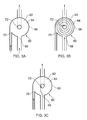
Figure 3a is plan view of a vortex amplifier for use in embodiments of the invention; -
Figure 3b shows the vortex amplifier ofFigure 3a in a high resistance state; -
Figure 3c shows the vortex amplifier ofFigure 3a in a low resistance state; -
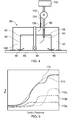
Figure 4 is a schematic representation of a controlled chamber arrangement in accordance with an embodiment of the present invention; -
Figure 5 shows the contributions of three flow controllers in producing a characteristic plot of vent flow quantity against sealing performance. - With reference to
Figure 1 , a gas turbine engine is generally indicated at 10, having a principal androtational axis 11. Theengine 10 comprises, in axial flow series, anair intake 12, apropulsive fan 13, anintermediate pressure compressor 14, a high-pressure compressor 15,combustion equipment 16, a high-pressure turbine 17, andintermediate pressure turbine 18, a low-pressure turbine 19 and anexhaust nozzle 20. Anacelle 21 generally surrounds theengine 10 and defines both theintake 12 and theexhaust nozzle 20. - The
gas turbine engine 10 works in the conventional manner so that air entering theintake 12 is accelerated by thefan 13 to produce two air flows: a first air flow into theintermediate pressure compressor 14 and a second air flow which passes through abypass duct 22 to provide propulsive thrust. Theintermediate pressure compressor 14 compresses the air flow directed into it before delivering that air to thehigh pressure compressor 15 where further compression takes place. - The compressed air exhausted from the high-
pressure compressor 15 is directed into thecombustion equipment 16 where it is mixed with fuel and the mixture combusted. The resultant hot combustion products then expand through, and thereby drive the high, intermediate and low-pressure turbines nozzle 20 to provide additional propulsive thrust. The high 17, intermediate 18 and low 19 pressure turbines drive respectively thehigh pressure compressor 15,intermediate pressure compressor 14 andfan 13, each by suitable interconnecting shaft. - Each of the interconnecting shafts is supported by a number of bearing arrangements. In prior art systems each bearing arrangement has been contained within a pressure controlled
chamber arrangement 30 such as that shown inFigure 2 . Thechamber arrangement 30 comprises a bearingchamber 32 having achamber wall 34. A gasturbine engine shaft 36 passes through the centre of thechamber 32, rotationally supported by a bearingarrangement 38.Seals 40 are provided at the rotating to static interface between thechamber wall 34 andshaft 36. Theseals 40 provide a fluid leakage path between the outside 42 and inside 44 of the bearingchamber 32. - The bearing
arrangement 38 needs lubrication and cooling. Oil is delivered to the inside 44 of the bearingchamber 32 via an oil line (not shown) to lubricate and cool thebearing arrangement 38. The used oil is pumped out of the bearingchamber 32 via a scavenge line (not shown), is processed to remove air and cool the oil and is returned to an oil tank (not shown). - The pressure controlled
chamber arrangement 30 also comprises avent line 46 which has aninlet 48 in fluid communication with the inside 44 of the bearingchamber 32. A flow restrictor 50 (fixed geometry orifice plate) and air/oil separation device 52 are provided in thevent line 46. Thevent line 46 passes through thechamber wall 34 and terminates with an exhaust to atmosphere (not shown). - In use it is desired that there be a constant flow of fluid from the outside 42 to the inside 44 of the bearing
chamber 32 via the leakage paths in order to prevent the leakage of oil from the bearingchamber 32. To this end the area surrounding the bearing chamber 32 (a buffer 53) is maintained at an elevated pressure using compressor bleed air. Additionally fluid is removed from the bearingchamber 32 via thevent line 46. Where theseals 40 are giving the desired sealing performance, the vent flow leaving the inside 44 of the bearingchamber 32 and elevated pressure outside 42 of the bearingchamber 32 generally gives a moderate pressure differential across theseals 40 sufficient to cause a desired level of fluid leakage through the fluid leakage paths. The flow restrictor 50 controls the quantity of fluid removed from the bearingchamber 32 via thevent line 46. - Referring now to
Figure 3a a vortex device, in this case a vortex amplifier is generally shown at 60. Thevortex amplifier 60 has avortex chamber 62. Thevortex chamber 62 is of substantially disc like shape, having parallel and opposed top 64 and bottom (not shown) walls and acurved side wall 66 spanning the gap between the top 64 and bottom walls and joining them at their perimeters. - The
vortex chamber 62 is fluid tight with the exception of avent inlet 68 for introducing a vent flow, acontrol inlet 70 for introducing a control fluid flow and avent outlet 72 for draining the control and vent flows. Thevent inlet 68 is provided in and from a direction perpendicular to theside wall 66. Thecontrol inlet 70 is provided in and from a direction tangential to its point of entry at theside wall 66. Thevent outlet 72 is provided in and towards a direction perpendicular to the centre of the bottom wall. - In use the
vortex chamber 62 is capable of providing different degrees of resistance to the flow of fluid from thevent inlet 68 to thevent outlet 72 through variation of the fluid pressure introduced via thecontrol inlet 70. Thevortex chamber 62 can therefore be used to control the quantity of fluid that passes through thevortex amplifier 60 from thevent inlet 68 to thevent outlet 72. - With reference to
Figure 3b , thevortex amplifier 60 is shown in a high resistance state. In this state the pressure of the control fluid flow is relatively high and/or the pressure of the vent flow is relatively low. The control fluid flow is encouraged to form a vortex, being introduced parallel to and subsequently turned by theside wall 66. In the high resistance state the relative fluid pressures of the vent and control fluid flows mean that the control fluid flow can form a relatively strong and stable vortex. The vortex prevents efficient, relatively direct flow of the vent flow from thevent inlet 68 to thevent outlet 72, limiting the quantity of vent flow passing through thevortex amplifier 60. - With reference to
Figure 3c , thevortex amplifier 60 is shown in a low resistance state. In this state the pressure of the control fluid flow is relatively low and/or the pressure of the vent flow is relatively high. In the low resistance state the relative fluid pressures of the vent and control fluid flows mean that the control fluid flow cannot form a relatively strong and stable vortex. The vortex is weakened by the vent flow which is consequently able to pass more efficiently and directly from thevent inlet 68 to thevent outlet 72. The quantity of vent flow passing through thevortex amplifier 60 is therefore increased by comparison with the high resistance state ofFigure 3b . - Referring now to
Figure 4 a pressure controlled chamber arrangement is generally shown at 80. Thechamber arrangement 80 comprises a chamber, in this case a bearingchamber 82, having achamber wall 84. A gasturbine engine shaft 86 passes through the centre of thechamber 82, rotationally supported by a bearingarrangement 88.Seals 90 are provided at the rotating to static interface between thechamber wall 84 andshaft 86. Theseals 90 provide a fluid leakage path between the outside 92 and inside 94 of the bearingchamber 82. - The bearing
arrangement 88 needs lubrication and cooling. Oil is delivered to the inside 94 bearingchamber 82 via an oil line (not shown) to lubricate and cool thebearing arrangement 88. The used oil is pumped out of the bearingchamber 82 via a scavenge line (not shown), is processed to remove air and cool the oil and is returned to an oil tank (not shown). - The pressure controlled
chamber arrangement 80 also comprises avent line 96 which has aninlet 98 in fluid communication with the inside 94 of the bearingchamber 82. A flow controller, in this case thevortex amplifier 60, and an air/oil separation device 100 are provided in thevent line 96. Thevent line 96 passes through thechamber wall 84 and terminates with an exhaust to atmosphere (not shown). - The
vortex amplifier 60 is connected to thevent line 96 by thevent inlet 68 on the inlet side and thevent outlet 72 on the outlet side. Thecontrol inlet 70 of thevortex amplifier 60 is connected to adownstream end 102 of acontrol line 104. Anupstream end 106 of thecontrol line 102 is in fluid communication with a source of control fluid, specifically pressurised bleed fluid surrounding theseals 90 in a cavity 108 (known as a buffer) surrounding thechamber 82. - In use it is desired that there be a constant flow of fluid from the outside 92 to the inside 94 of the bearing
chamber 82 via the leakage paths in order to prevent the leakage of oil from the bearingchamber 82. To this end the area surrounding the bearingchamber 82 is maintained at an elevated pressure using compressor bleed air. Additionally fluid is removed from the bearingchamber 82 via thevent line 96. The vent flow leaving the inside 94 of the bearingchamber 82 and elevated pressure outside 92 of the bearingchamber 82 generally gives a moderate pressure differential across theseals 90 sufficient to cause a desired level of fluid leakage through the fluid leakage paths. - The quantity of fluid removed from the inside 94 of the bearing
chamber 82 in the vent flow, is controlled by thevortex amplifier 60 in accordance with the sealing performance provided by theseals 90. - Where, as may occur from time to time, there is a decrease in the sealing performance provided by the
seals 90, the pressure differential between the inside 94 and outside 92 of the bearingchamber 82 will decrease. Because the control fluid flow to thevortex amplifier 60 comes from fluid in thecavity 108 surrounding the bearing chamber 82 (and specifically the fluid surrounding the outside of the seals 90), the pressure differential decrease will cause a weakening of the vortex and an increase in the quantity of fluid removed from the inside 94 of thechamber 82. As will be appreciated an increase in the sealing performance would have the opposite effect. Thevortex amplifier 60 therefore compensates for a change in sealing performance by increasing or decreasing the quantity of fluid removed from the inside 94 of the bearingchamber 82 accordingly. Further, in this embodiment, the quantity of fluid removed from the inside 94 of the bearingchamber 82 is tuned by thevortex amplifier 60 maintain an equilibrium condition where the pressure ratio across theseals 90 is substantially consistent regardless of the sealing performance. This protects theseals 90, reduces the likelihood of oil leakage from the bearingchamber 82 and increases efficiency. - As will be appreciated the control exerted by the
vortex amplifier 60 is passive in the sense that thevortex amplifier 60 is not actively controlled (e.g. via signals from an engine electronic control (EEC)). The passive control exerted by thevortex amplifier 60 is in part possible because the control fluid flow source gives a pressure with a known relationship to the pressure around theseals 90 external to the bearingchamber 82. Indeed the control is simplified because the source further gives a control fluid flow pressure proportional to and in fact the same as the pressure around theseals 90 external to the bearingchamber 82. - As will be appreciated, in some embodiments of the invention it may not be possible to tune a single flow controller such as the
vortex amplifier 60 to maintain an equilibrium condition where the pressure ratio across theseals 90 is substantially consistent regardless of the sealing performance (or indeed to achieve an alternative desired characteristic). With reference now toFigure 5 , the use of multiple flow controllers may however facilitate such tuning to give a particular vent flow quantity v sealing performance characteristic.Figure 5 shows the different vent flow quantity performance (vertical axis) for threedistinct vortex amplifiers vortex amplifiers characteristic 114. - It will be understood that the invention is not limited to the embodiments above-described and various modifications and improvements can be made without departing from the various concepts described herein. Except where mutually exclusive, any of the features may be employed separately or in combination with any other features and the invention extends to and includes all combinations and sub-combinations of one or more features described herein in any form of pressure controlled chamber arrangement.
Claims (15)
- A pressure controlled chamber arrangement comprising a chamber, one or more seals arranged in use to limit fluid flow between the inside and outside of the chamber and a vent system arranged in use to remove a vent flow of fluid from the inside of the chamber and at least contribute to the formation of a pressure drop across the one or more seals from the outside to the inside of the chamber, the vent system comprising a flow controller arranged in use to control the quantity of fluid removal via the vent system in accordance with the sealing performance provided by the one or more seals, the vent system giving increased quantity of fluid removal for decreased sealing performance.
- A pressure controlled chamber arrangement according to claim 1 where the flow controller biases the apparatus towards an equilibrium condition where the pressure ratio across the seals is substantially consistent regardless of the sealing performance.
- A pressure controlled chamber arrangement according to claim 1 or claim 2 where the flow controller uses a control fluid flow to control the quantity of fluid removal via the vent system.
- A pressure controlled chamber arrangement according to claim 3 where the flow controller is arranged such that an increase in vent flow pressure relative to control fluid flow pressure results in an increase in the quantity of fluid removal.
- A pressure controlled chamber arrangement according to claim 3 or claim 4 where the control fluid flow is taken from a source giving a control fluid flow pressure with a known relationship to the pressure around the seals external to the chamber.
- A pressure controlled chamber arrangement according to any of claims 3 to 5 where the control fluid flow is taken from a source giving a control fluid flow pressure proportional to the pressure around the seals external to the chamber.
- A pressure controlled chamber arrangement according to any of claims 3 to 6 where the control fluid flow is taken from a source giving a control fluid flow pressure that is the same as the pressure around the seals external to the chamber.
- A pressure controlled chamber arrangement according to any of claims 3 to 7 where the control fluid flow is taken from a cavity surrounding the chamber.
- A pressure controlled chamber arrangement according to any of claims 3 to 6 where the control fluid flow is taken from a source giving a pressure that is greater than the pressure around the seals external to the chamber.
- A pressure controlled chamber arrangement according to any preceding claim where the flow controller is a vortex device.
- A pressure controlled chamber arrangement according to claim 10 where the control fluid flow and vent flow are combined in a vortex chamber of the vortex device, with the control fluid flow being directed into the vortex chamber in a manner so as it is encouraged to generate a vortex that inhibits passage of the vent flow through the vortex chamber from a vent flow inlet to a vent flow outlet.
- A pressure controlled chamber arrangement according to claim 11 where the vortex chamber is arranged so that changes in the pressure differential between the control fluid flow and vent flow cause a change in the strength of the vortex and a consequent change in the quantity of fluid removed via the vent system.
- A pressure controlled chamber arrangement according to any preceding claim where the chamber is a bearing chamber.
- A gas turbine engine having a pressure controlled chamber arrangement in accordance with any of claims 1 to 13.
- A method of controlling fluid removal from a pressure controlled chamber arrangement comprising increasing the quantity of fluid removal where sealing performance for limiting fluid flow between the inside and outside of a chamber of the arrangement is diminished.
Applications Claiming Priority (1)
| Application Number | Priority Date | Filing Date | Title |
|---|---|---|---|
| GBGB1412869.8A GB201412869D0 (en) | 2014-07-21 | 2014-07-21 | Pressure controlled chamber |
Publications (1)
| Publication Number | Publication Date |
|---|---|
| EP2977566A1 true EP2977566A1 (en) | 2016-01-27 |
Family
ID=51494861
Family Applications (1)
| Application Number | Title | Priority Date | Filing Date |
|---|---|---|---|
| EP15176769.6A Withdrawn EP2977566A1 (en) | 2014-07-21 | 2015-07-15 | Pressure controlled chamber |
Country Status (3)
| Country | Link |
|---|---|
| US (1) | US9625101B2 (en) |
| EP (1) | EP2977566A1 (en) |
| GB (1) | GB201412869D0 (en) |
Cited By (1)
| Publication number | Priority date | Publication date | Assignee | Title |
|---|---|---|---|---|
| EP3318728A1 (en) * | 2016-11-04 | 2018-05-09 | United Technologies Corporation | Variable volume bearing compartment |
Citations (3)
| Publication number | Priority date | Publication date | Assignee | Title |
|---|---|---|---|---|
| GB2119858A (en) * | 1982-05-13 | 1983-11-23 | United Technologies Corp | Means for controlling air scavenge pressure in the bearing compartment of gas turbines |
| GB2437969A (en) * | 2006-04-13 | 2007-11-14 | Rolls Royce Plc | Fluid flow control system |
| US20090288384A1 (en) * | 2001-11-29 | 2009-11-26 | Charles Robert Granitz | System for reducing oil consumption in gas turbine engines |
Family Cites Families (26)
| Publication number | Priority date | Publication date | Assignee | Title |
|---|---|---|---|---|
| US3195303A (en) | 1962-01-22 | 1965-07-20 | Bendix Corp | Vortex valve |
| GB1211788A (en) | 1968-11-12 | 1970-11-11 | Hobson Ltd H M | An improved fuel flow proportioner |
| GB1254612A (en) | 1969-01-20 | 1971-11-24 | Hobson Ltd H M | An improved fuel control system for a gas turbine engine |
| US3641766A (en) | 1969-11-26 | 1972-02-15 | Gen Electric | Gas turbine engine constant speed thrust modulation |
| US3631684A (en) | 1970-09-04 | 1972-01-04 | Ranco Inc | Step-by-step control of refrigerant return in a compressor-condenser-expander system |
| JPS4928503U (en) | 1972-06-14 | 1974-03-12 | ||
| US4621981A (en) | 1982-11-01 | 1986-11-11 | Borg-Warner Corporation | Pump improvement |
| GB8908067D0 (en) | 1989-04-11 | 1989-05-24 | Atomic Energy Authority Uk | A fluidic ventillation control system |
| GB8920695D0 (en) | 1989-09-13 | 1989-10-25 | Rolls Royce Plc | Engine cooling system protection device |
| US5322373A (en) * | 1993-04-30 | 1994-06-21 | Reliance Electric Industrial Co. | Vented, oil bath lubricated bearing structure for a motor |
| GB2391959B (en) * | 2002-08-13 | 2006-01-04 | Rolls Royce Plc | Vents for bearing chambers |
| US7591631B2 (en) * | 2006-06-30 | 2009-09-22 | United Technologies Corporation | Flow delivery system for seals |
| US7654085B2 (en) | 2006-08-28 | 2010-02-02 | Elijah Dumas | System of an induced flow machine |
| US7935164B2 (en) * | 2007-11-28 | 2011-05-03 | General Electric Company | Vortex air-oil separator system |
| DE102007058953A1 (en) * | 2007-12-07 | 2009-06-10 | Rolls-Royce Deutschland Ltd & Co Kg | Bearing chamber pressure system |
| GB2457427A (en) | 2007-12-14 | 2009-08-19 | Rolls Royce Plc | Gas turbine engine cooling flow modulation arrangement comprising fluidic valves |
| US8307626B2 (en) | 2009-02-26 | 2012-11-13 | United Technologies Corporation | Auxiliary pump system for fan drive gear system |
| US8051869B2 (en) | 2009-05-22 | 2011-11-08 | United Technologies Corporation | Gravity operated valve |
| US8230974B2 (en) | 2009-05-22 | 2012-07-31 | United Technologies Corporation | Windmill and zero gravity lubrication system for a gas turbine engine |
| GB201103890D0 (en) | 2011-03-08 | 2011-04-20 | Rolls Royce Plc | Gas turbine engine swirled cooling air |
| GB201109799D0 (en) * | 2011-06-13 | 2011-07-27 | Rolls Royce Plc | A bearing chamber apparatus |
| GB2495092B (en) * | 2011-09-28 | 2014-01-01 | Rolls Royce Plc | Sealing arrangement |
| US10598222B2 (en) * | 2012-01-03 | 2020-03-24 | New Way Machine Components, Inc. | Air bearing for use as seal |
| GB201200290D0 (en) * | 2012-01-10 | 2012-02-22 | Rolls Royce Plc | Gas turbine engine buffer seals |
| DE102012218135B4 (en) * | 2012-10-04 | 2017-07-27 | Rolls-Royce Deutschland Ltd & Co Kg | Aero engine storage chamber venting system and method of providing a desired pressure ratio to bearing chamber seals of an air sealed storage chamber |
| IL233615A (en) * | 2014-07-10 | 2016-02-29 | Ettem Eng S A Ltd | Method and devices for discharging contaminants out of a seal chamber |
-
2014
- 2014-07-21 GB GBGB1412869.8A patent/GB201412869D0/en not_active Ceased
-
2015
- 2015-07-15 US US14/800,529 patent/US9625101B2/en not_active Expired - Fee Related
- 2015-07-15 EP EP15176769.6A patent/EP2977566A1/en not_active Withdrawn
Patent Citations (3)
| Publication number | Priority date | Publication date | Assignee | Title |
|---|---|---|---|---|
| GB2119858A (en) * | 1982-05-13 | 1983-11-23 | United Technologies Corp | Means for controlling air scavenge pressure in the bearing compartment of gas turbines |
| US20090288384A1 (en) * | 2001-11-29 | 2009-11-26 | Charles Robert Granitz | System for reducing oil consumption in gas turbine engines |
| GB2437969A (en) * | 2006-04-13 | 2007-11-14 | Rolls Royce Plc | Fluid flow control system |
Cited By (2)
| Publication number | Priority date | Publication date | Assignee | Title |
|---|---|---|---|---|
| EP3318728A1 (en) * | 2016-11-04 | 2018-05-09 | United Technologies Corporation | Variable volume bearing compartment |
| US10520035B2 (en) | 2016-11-04 | 2019-12-31 | United Technologies Corporation | Variable volume bearing compartment |
Also Published As
| Publication number | Publication date |
|---|---|
| GB201412869D0 (en) | 2014-09-03 |
| US9625101B2 (en) | 2017-04-18 |
| US20160018058A1 (en) | 2016-01-21 |
Similar Documents
| Publication | Publication Date | Title |
|---|---|---|
| US7584619B2 (en) | System for reducing oil consumption in gas turbine engines | |
| US20170298955A1 (en) | System and method for rapid pressurization of a motor/bearing cooling loop for a hermetically sealed motor/compressor system | |
| EP2789806B1 (en) | Methods and systems for preventing lube oil leakage in gas turbines | |
| CN103375192B (en) | Oil supply tank sealing member pressue device | |
| US10502081B2 (en) | Turbomachine bearing housing | |
| CN110388283A (en) | Gas turbine engine | |
| EP2598756B1 (en) | Method and system for reducing seal gas consumption and settle-out pressure reduction in high-pressure compression systems | |
| US10612436B2 (en) | Deoiler for a gas turbine engine | |
| US20130139516A1 (en) | Cooling system for gas turbine load coupling | |
| CN107060906A (en) | System and method for reducing engine temperature after shutdown | |
| US10502141B2 (en) | Apparatus and method for controlling a pressure differential across a seal of a bearing chamber | |
| EP3114353B1 (en) | Method and system for operating a back-to-back compressor with a side stream | |
| US20190309765A1 (en) | Nitrogen purge of compressor dry seal | |
| US8956106B2 (en) | Adaptive eductor system | |
| US9625101B2 (en) | Pressure controlled chamber | |
| US9567987B2 (en) | Chamber fluid removal system | |
| US20140255148A1 (en) | Gas turbine engine clearance control | |
| US9003766B2 (en) | Gas cooler and method for cooling gas | |
| EP3330496B1 (en) | Bearing compartment scavenge control | |
| Garceau et al. | Methane Emissions Reduction Solutions: Product Development and Standardization |
Legal Events
| Date | Code | Title | Description |
|---|---|---|---|
| PUAI | Public reference made under article 153(3) epc to a published international application that has entered the european phase |
Free format text: ORIGINAL CODE: 0009012 |
|
| AK | Designated contracting states |
Kind code of ref document: A1 Designated state(s): AL AT BE BG CH CY CZ DE DK EE ES FI FR GB GR HR HU IE IS IT LI LT LU LV MC MK MT NL NO PL PT RO RS SE SI SK SM TR |
|
| AX | Request for extension of the european patent |
Extension state: BA ME |
|
| 17P | Request for examination filed |
Effective date: 20160713 |
|
| RBV | Designated contracting states (corrected) |
Designated state(s): AL AT BE BG CH CY CZ DE DK EE ES FI FR GB GR HR HU IE IS IT LI LT LU LV MC MK MT NL NO PL PT RO RS SE SI SK SM TR |
|
| RAP1 | Party data changed (applicant data changed or rights of an application transferred) |
Owner name: ROLLS-ROYCE PLC |
|
| STAA | Information on the status of an ep patent application or granted ep patent |
Free format text: STATUS: REQUEST FOR EXAMINATION WAS MADE |
|
| STAA | Information on the status of an ep patent application or granted ep patent |
Free format text: STATUS: THE APPLICATION IS DEEMED TO BE WITHDRAWN |
|
| 18D | Application deemed to be withdrawn |
Effective date: 20210202 |