EP2977562A1 - Bearing compartment sealing system - Google Patents
Bearing compartment sealing system Download PDFInfo
- Publication number
- EP2977562A1 EP2977562A1 EP15177838.8A EP15177838A EP2977562A1 EP 2977562 A1 EP2977562 A1 EP 2977562A1 EP 15177838 A EP15177838 A EP 15177838A EP 2977562 A1 EP2977562 A1 EP 2977562A1
- Authority
- EP
- European Patent Office
- Prior art keywords
- runner
- seal
- sealing system
- bearing compartment
- oil
- Prior art date
- Legal status (The legal status is an assumption and is not a legal conclusion. Google has not performed a legal analysis and makes no representation as to the accuracy of the status listed.)
- Granted
Links
Images



Classifications
-
- F—MECHANICAL ENGINEERING; LIGHTING; HEATING; WEAPONS; BLASTING
- F01—MACHINES OR ENGINES IN GENERAL; ENGINE PLANTS IN GENERAL; STEAM ENGINES
- F01D—NON-POSITIVE DISPLACEMENT MACHINES OR ENGINES, e.g. STEAM TURBINES
- F01D25/00—Component parts, details, or accessories, not provided for in, or of interest apart from, other groups
- F01D25/08—Cooling; Heating; Heat-insulation
- F01D25/12—Cooling
- F01D25/125—Cooling of bearings
-
- F—MECHANICAL ENGINEERING; LIGHTING; HEATING; WEAPONS; BLASTING
- F01—MACHINES OR ENGINES IN GENERAL; ENGINE PLANTS IN GENERAL; STEAM ENGINES
- F01D—NON-POSITIVE DISPLACEMENT MACHINES OR ENGINES, e.g. STEAM TURBINES
- F01D11/00—Preventing or minimising internal leakage of working-fluid, e.g. between stages
- F01D11/003—Preventing or minimising internal leakage of working-fluid, e.g. between stages by packing rings; Mechanical seals
-
- F—MECHANICAL ENGINEERING; LIGHTING; HEATING; WEAPONS; BLASTING
- F01—MACHINES OR ENGINES IN GENERAL; ENGINE PLANTS IN GENERAL; STEAM ENGINES
- F01D—NON-POSITIVE DISPLACEMENT MACHINES OR ENGINES, e.g. STEAM TURBINES
- F01D11/00—Preventing or minimising internal leakage of working-fluid, e.g. between stages
- F01D11/02—Preventing or minimising internal leakage of working-fluid, e.g. between stages by non-contact sealings, e.g. of labyrinth type
-
- F—MECHANICAL ENGINEERING; LIGHTING; HEATING; WEAPONS; BLASTING
- F01—MACHINES OR ENGINES IN GENERAL; ENGINE PLANTS IN GENERAL; STEAM ENGINES
- F01D—NON-POSITIVE DISPLACEMENT MACHINES OR ENGINES, e.g. STEAM TURBINES
- F01D25/00—Component parts, details, or accessories, not provided for in, or of interest apart from, other groups
- F01D25/18—Lubricating arrangements
- F01D25/183—Sealing means
-
- F—MECHANICAL ENGINEERING; LIGHTING; HEATING; WEAPONS; BLASTING
- F16—ENGINEERING ELEMENTS AND UNITS; GENERAL MEASURES FOR PRODUCING AND MAINTAINING EFFECTIVE FUNCTIONING OF MACHINES OR INSTALLATIONS; THERMAL INSULATION IN GENERAL
- F16C—SHAFTS; FLEXIBLE SHAFTS; ELEMENTS OR CRANKSHAFT MECHANISMS; ROTARY BODIES OTHER THAN GEARING ELEMENTS; BEARINGS
- F16C33/00—Parts of bearings; Special methods for making bearings or parts thereof
- F16C33/30—Parts of ball or roller bearings
- F16C33/66—Special parts or details in view of lubrication
- F16C33/6637—Special parts or details in view of lubrication with liquid lubricant
-
- F—MECHANICAL ENGINEERING; LIGHTING; HEATING; WEAPONS; BLASTING
- F16—ENGINEERING ELEMENTS AND UNITS; GENERAL MEASURES FOR PRODUCING AND MAINTAINING EFFECTIVE FUNCTIONING OF MACHINES OR INSTALLATIONS; THERMAL INSULATION IN GENERAL
- F16C—SHAFTS; FLEXIBLE SHAFTS; ELEMENTS OR CRANKSHAFT MECHANISMS; ROTARY BODIES OTHER THAN GEARING ELEMENTS; BEARINGS
- F16C33/00—Parts of bearings; Special methods for making bearings or parts thereof
- F16C33/72—Sealings
- F16C33/76—Sealings of ball or roller bearings
- F16C33/78—Sealings of ball or roller bearings with a diaphragm, disc, or ring, with or without resilient members
- F16C33/7896—Sealings of ball or roller bearings with a diaphragm, disc, or ring, with or without resilient members with two or more discrete sealings arranged in series
-
- F—MECHANICAL ENGINEERING; LIGHTING; HEATING; WEAPONS; BLASTING
- F16—ENGINEERING ELEMENTS AND UNITS; GENERAL MEASURES FOR PRODUCING AND MAINTAINING EFFECTIVE FUNCTIONING OF MACHINES OR INSTALLATIONS; THERMAL INSULATION IN GENERAL
- F16C—SHAFTS; FLEXIBLE SHAFTS; ELEMENTS OR CRANKSHAFT MECHANISMS; ROTARY BODIES OTHER THAN GEARING ELEMENTS; BEARINGS
- F16C33/00—Parts of bearings; Special methods for making bearings or parts thereof
- F16C33/72—Sealings
- F16C33/76—Sealings of ball or roller bearings
- F16C33/80—Labyrinth sealings
- F16C33/805—Labyrinth sealings in addition to other sealings, e.g. dirt guards to protect sealings with sealing lips
-
- F—MECHANICAL ENGINEERING; LIGHTING; HEATING; WEAPONS; BLASTING
- F16—ENGINEERING ELEMENTS AND UNITS; GENERAL MEASURES FOR PRODUCING AND MAINTAINING EFFECTIVE FUNCTIONING OF MACHINES OR INSTALLATIONS; THERMAL INSULATION IN GENERAL
- F16J—PISTONS; CYLINDERS; SEALINGS
- F16J15/00—Sealings
- F16J15/16—Sealings between relatively-moving surfaces
- F16J15/164—Sealings between relatively-moving surfaces the sealing action depending on movements; pressure difference, temperature or presence of leaking fluid
-
- F—MECHANICAL ENGINEERING; LIGHTING; HEATING; WEAPONS; BLASTING
- F16—ENGINEERING ELEMENTS AND UNITS; GENERAL MEASURES FOR PRODUCING AND MAINTAINING EFFECTIVE FUNCTIONING OF MACHINES OR INSTALLATIONS; THERMAL INSULATION IN GENERAL
- F16J—PISTONS; CYLINDERS; SEALINGS
- F16J15/00—Sealings
- F16J15/44—Free-space packings
- F16J15/441—Free-space packings with floating ring
- F16J15/442—Free-space packings with floating ring segmented
-
- F—MECHANICAL ENGINEERING; LIGHTING; HEATING; WEAPONS; BLASTING
- F05—INDEXING SCHEMES RELATING TO ENGINES OR PUMPS IN VARIOUS SUBCLASSES OF CLASSES F01-F04
- F05D—INDEXING SCHEME FOR ASPECTS RELATING TO NON-POSITIVE-DISPLACEMENT MACHINES OR ENGINES, GAS-TURBINES OR JET-PROPULSION PLANTS
- F05D2220/00—Application
- F05D2220/30—Application in turbines
- F05D2220/32—Application in turbines in gas turbines
-
- F—MECHANICAL ENGINEERING; LIGHTING; HEATING; WEAPONS; BLASTING
- F05—INDEXING SCHEMES RELATING TO ENGINES OR PUMPS IN VARIOUS SUBCLASSES OF CLASSES F01-F04
- F05D—INDEXING SCHEME FOR ASPECTS RELATING TO NON-POSITIVE-DISPLACEMENT MACHINES OR ENGINES, GAS-TURBINES OR JET-PROPULSION PLANTS
- F05D2240/00—Components
- F05D2240/55—Seals
-
- F—MECHANICAL ENGINEERING; LIGHTING; HEATING; WEAPONS; BLASTING
- F05—INDEXING SCHEMES RELATING TO ENGINES OR PUMPS IN VARIOUS SUBCLASSES OF CLASSES F01-F04
- F05D—INDEXING SCHEME FOR ASPECTS RELATING TO NON-POSITIVE-DISPLACEMENT MACHINES OR ENGINES, GAS-TURBINES OR JET-PROPULSION PLANTS
- F05D2260/00—Function
- F05D2260/20—Heat transfer, e.g. cooling
-
- F—MECHANICAL ENGINEERING; LIGHTING; HEATING; WEAPONS; BLASTING
- F05—INDEXING SCHEMES RELATING TO ENGINES OR PUMPS IN VARIOUS SUBCLASSES OF CLASSES F01-F04
- F05D—INDEXING SCHEME FOR ASPECTS RELATING TO NON-POSITIVE-DISPLACEMENT MACHINES OR ENGINES, GAS-TURBINES OR JET-PROPULSION PLANTS
- F05D2260/00—Function
- F05D2260/98—Lubrication
-
- F—MECHANICAL ENGINEERING; LIGHTING; HEATING; WEAPONS; BLASTING
- F05—INDEXING SCHEMES RELATING TO ENGINES OR PUMPS IN VARIOUS SUBCLASSES OF CLASSES F01-F04
- F05D—INDEXING SCHEME FOR ASPECTS RELATING TO NON-POSITIVE-DISPLACEMENT MACHINES OR ENGINES, GAS-TURBINES OR JET-PROPULSION PLANTS
- F05D2300/00—Materials; Properties thereof
- F05D2300/10—Metals, alloys or intermetallic compounds
- F05D2300/17—Alloys
- F05D2300/175—Superalloys
-
- F—MECHANICAL ENGINEERING; LIGHTING; HEATING; WEAPONS; BLASTING
- F05—INDEXING SCHEMES RELATING TO ENGINES OR PUMPS IN VARIOUS SUBCLASSES OF CLASSES F01-F04
- F05D—INDEXING SCHEME FOR ASPECTS RELATING TO NON-POSITIVE-DISPLACEMENT MACHINES OR ENGINES, GAS-TURBINES OR JET-PROPULSION PLANTS
- F05D2300/00—Materials; Properties thereof
- F05D2300/50—Intrinsic material properties or characteristics
- F05D2300/502—Thermal properties
- F05D2300/5021—Expansivity
-
- F—MECHANICAL ENGINEERING; LIGHTING; HEATING; WEAPONS; BLASTING
- F16—ENGINEERING ELEMENTS AND UNITS; GENERAL MEASURES FOR PRODUCING AND MAINTAINING EFFECTIVE FUNCTIONING OF MACHINES OR INSTALLATIONS; THERMAL INSULATION IN GENERAL
- F16C—SHAFTS; FLEXIBLE SHAFTS; ELEMENTS OR CRANKSHAFT MECHANISMS; ROTARY BODIES OTHER THAN GEARING ELEMENTS; BEARINGS
- F16C19/00—Bearings with rolling contact, for exclusively rotary movement
- F16C19/02—Bearings with rolling contact, for exclusively rotary movement with bearing balls essentially of the same size in one or more circular rows
- F16C19/04—Bearings with rolling contact, for exclusively rotary movement with bearing balls essentially of the same size in one or more circular rows for radial load mainly
- F16C19/06—Bearings with rolling contact, for exclusively rotary movement with bearing balls essentially of the same size in one or more circular rows for radial load mainly with a single row or balls
-
- F—MECHANICAL ENGINEERING; LIGHTING; HEATING; WEAPONS; BLASTING
- F16—ENGINEERING ELEMENTS AND UNITS; GENERAL MEASURES FOR PRODUCING AND MAINTAINING EFFECTIVE FUNCTIONING OF MACHINES OR INSTALLATIONS; THERMAL INSULATION IN GENERAL
- F16C—SHAFTS; FLEXIBLE SHAFTS; ELEMENTS OR CRANKSHAFT MECHANISMS; ROTARY BODIES OTHER THAN GEARING ELEMENTS; BEARINGS
- F16C2360/00—Engines or pumps
- F16C2360/23—Gas turbine engines
Definitions
- the present disclosure relates to seals for a gas turbine engine and, more particularly, to sealing systems including a runner.
- Seal systems with circumferential elements are often used in the high temperature environment of gas turbine engines where a rotational structure extends through stationary structures, for example, to seal mainshaft bearing compartments.
- Conventional methods and systems can employ a direct oil jet to cool circumferential sealing elements.
- the conventional direct jet oil directs oil into the under side of a bore side of a runner for cooling such that the direct oil supply is used to cool the runner and pull heat away from contacting surfaces of the runner.
- runner assemblies for circumferential seal assemblies Disclosed and claimed herein are runner assemblies for circumferential seal assemblies.
- One embodiment is directed to a sealing system for a bearing compartment, the sealing system including a runner configured to extend circumferentially around a rotating component, wherein the runner is formed of a material with low radial thermal growth, wherein the runner is configured to fit to the rotating component to remove heat away from the runner and wherein the runner includes an outer surface configured to provide passive cooling for the runner in the bearing compartment.
- the sealing system also includes a seal configured to operate with the runner, wherein the seal includes a clearance seal on an air side of the runner.
- the runner is substantially cylindrical with a hollow core configured for the rotating component.
- the material of the runner includes a nickel alloy.
- the runner is configured to be fit to the rotating shaft by an interference fit.
- the outer surface of the runner extends into the bearing compartment a distance in order to receive passive oil to cool the runner.
- the runner is configured to operate without direct oil cooling.
- the runner includes a substantially rectangular cut-out along an inner surface of the runner, wherein the width of the cut-out is dimensioned to maximize heat conduction away from the seal.
- the clearance seal is a stationary arch bound seal.
- the seal includes the one or more seal segments that form a segmented carbon seal for a bearing compartment of a gas turbine engine.
- the runner is configured to operate with a stator assembly including a contacting seal for an oil side and a clearance arch bound seal for an air side.
- Another embodiment is directed to a sealing system for a bearing compartment of a gas turbine engine, the sealing system including a runner configured to extend circumferentially around a rotating component, wherein the runner is formed of a material with low radial thermal growth, wherein the runner is configured to fit to the rotating component to remove heat away from the runner and wherein the runner includes an outer surface configured to provide passive cooling for the runner in the bearing compartment.
- the sealing system including a seal configured to operate with the runner, wherein the seal includes a clearance seal on an air side of the runner, and wherein the runner is configured to operate without direct oil cooling.
- a seal system including a runner.
- One embodiment is directed to a sealing system configured to seal oil in a bearing compartment.
- Bearing compartments need lubrication for cooling and lubricity.
- lubrication with oil can provide a number of factors, including removing heat and to provide lubricity.
- a seal system is provided to allow for passive cooling, such as passive cooling of the runner assembly without direct oil cooling (e.g., 0.0 pounds-per-minute (ppm) cooling).
- the seal system may be configured to allow for packaging seals in tight spaces relative to seal systems which require direct oil jets.
- the sealing system includes a rotating member or "runner" that interoperates with a stationary seal made of one or more carbon elements retained in a stationary housing.
- the stationary seal may include two carbon ring elements - one on the oil side of the bearing compartment and another (e.g., a clearance seal) on the air side of the bearing compartment, such that sealing is provided across mating surfaces that have radial orientation.
- a radial seal is provided.
- a sealing system is provided including stationary carbon seals that are circumferentially segmented.
- a runner may be provided with a cylindrical configuration.
- a carbon seal on an air side is preferred to be of a clearance seal.
- a clearance seal may relate to one of a non-contacting type seal, fully arch bound seal and seal in general that starts as a contact seal which wears into a non-contacting seal.
- Non-contacting type seals refer to seals where there is a small gap between the seal and the runner; therefore, the seal does not rub on the runner, and thus, generates very little heat.
- This type of a non-contacting circumferentially segmented carbon seal is typically referred to as an "arch-bound" seal.
- Embodiments described herein discuss an arch-bound seal within a sealing system having a runner configured to operate without a direct oil jet to the runner.
- the terms “a” or “an” shall mean one or more than one.
- the term “plurality” shall mean two or more than two.
- the term “another” is defined as a second or more.
- the terms “including” and/or “having” are open ended (e.g., comprising).
- the term “or” as used herein is to be interpreted as inclusive or meaning any one or any combination. Therefore, “A, B or C” means “any of the following: A; B; C; A and B; A and C; B and C; A, B and C". An exception to this definition will occur only when a combination of elements, functions, steps or acts are in some way inherently mutually exclusive.
- FIG. 1 depicts a cross-sectional representation of a gas turbine engine 100 according to one or more embodiments.
- the gas turbine engine 100 includes a bearing compartment, generally shown as 105, having circumferential seal and runner according to one or more embodiments.
- Bearing compartment 105 is shown with respect to shaft 106 and air supply 110 and cooling oil 115 and 120.
- Bearing compartment 105 may be configured to support a shaft 106 of turbine engine 100 with one or more bearings, such as bearing 125.
- a sealing system is provided for turbine engine 100. Exemplary embodiments of the sealing system are shown in FIGs. 2A-2D .
- a sealing system shown generally as 130, is provided including a seal which does not require direct oil cooling (e.g., a dedicated oil jet) for the runner and/or seal portion of the bearing compartment.
- Sealing system 130 may be configured for one or more of reduced heat generation, reduced thermal growth, improved heat transfer and/or to allow for passive oil cooling.
- Passive oil cooling may allow for a sealing assembly to operate without direct oil cooling. Unlike direct oil cooling, passive oil cooling allows for oil mist, for example, from cooling oil 115 and/or 120 to indirectly cool a runner. Oil mist can relate to oil which may be in bearing compartment 105.
- the gas turbine engine 100 generally incorporates a fan section, a compressor section, a combustor section and a turbine section among other systems or features.
- FIG. 1 is depicted as a gas turbine engine, it should be understood that the concepts described herein are not limited to use with gas turbine engines as the teachings may be applied to other types of engines or sealing systems in general.
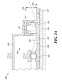
- FIGs. 2A-2D depict cross-sectional representations of bearing compartments including sealing systems according to one or more embodiments.
- FIG. 2A depicts sealing system 200 including runner 205 and seals 210 and 216. Sealing system 200 is shown relative to bearing compartment 215, which may be a bearing compartment of a gas turbine engine (e.g., bearing compartment 105 of FIG. 1 ). It should be appreciated that sealing system 200 may be configured for one or more types of bearing compartment, or gas turbine engine.
- bearing compartment 215 may be a bearing compartment of a gas turbine engine (e.g., bearing compartment 105 of FIG. 1 ). It should be appreciated that sealing system 200 may be configured for one or more types of bearing compartment, or gas turbine engine.
- sealing system 200 may be a circumferential sealing system having a stationary (e.g., non-rotating) assembly, such as seal 210, mounted to the static structure, such as structure 230, of bearing compartment 215 and a runner 205 mounted to a rotating component, such as one or more engine shafts represented as 206.
- a stationary (e.g., non-rotating) assembly such as seal 210
- static structure such as structure 230
- runner 205 mounted to a rotating component, such as one or more engine shafts represented as 206.
- Sealing system 200 may be configured to ensure that engine shaft(s) 206 are sealed at several points to prevent unwanted fluid leakage between, for example, engine compartments. Sealing system 200 may be configured for sealing a main shaft bearing compartment where, for example, separation is required for bearing lubrication oil in the bearing compartment from air side pressure.
- Runner 205 may be a circumferential runner for a circumferential seal assembly, such as sealing system 200.
- Runner 205 may be configured to extend circumferentially around a rotating component, such as shaft 206, such that at least a portion of the inward facing surface of runner 205 meets with shaft 206.
- runner 205 is substantially cylindrical with a hollow core, the core configured for a tight (e.g., interference) fit with shaft 206.
- Runner 205 is configured to fit to a rotating component, such as shaft 206, to remove heat away from the runner 205.
- Runner 205 includes an outer surface 207 configured to provide passive cooling for the runner in bearing compartment 215.
- surface 207 is an outward facing surface of runner 205 which extends into bearing compartment 215 towards bearing 245, such that surface 207 provides surface area for passive oil cooling exposure.
- the particular distance surface 207 extends into bearing compartment 215 may be based on the particular turbine, the particular engine, heat of the shaft, heat characteristics of the runner, etc.
- the outer surface 207 may be configured to intentionally protrude to expose runner 205 to oil mist 220 within bearing compartment 215 in order to enhance convective heat transfer.
- the amount outer surface 207 extends may be maximized based on available space within the bearing compartment 215.
- runner 205 may include a substantially rectangular cut-out 211 along an inner surface of the runner, wherein the width of the cut-out is arranged or dimensioned to maximize the heat conduction away from seal components 210 and 216 of the seal system.
- runner 205 is formed of a material with low radial thermal growth, such as a material including a nickel alloy.
- a material with low radial thermal growth such as a material including a nickel alloy.
- One benefit of employing a nickel alloy is a coefficient of thermal expansion that is very close to that of structural carbon. As a result, the carbon seal and the runner expand at nearly the same rate during operation.
- Runner 205 is configured to operate without direct oil cooling.
- bearing compartment may provide a certain amount of oil mist in the bearing compartment as the bearing itself will require oil for cooling. Cooling by means of a fluid, such as oil, removes the heat by convective heat transfer.
- Convective cooling for runner 205 may be provided by ambient oil mist within the bearing compartment. Unlike a direct oil jet, ambient oil mist may result from oil that is applied to components in the bearing compartment, but does not require a particular jet or directed application of a jet. An ambient mist may range from a molecule of lubricant to a full direct spray. The volume of ambient mist depends on the compartment and may be relative to the amount of oil for the compartment.
- the mist is droplets of oil naturally generated in a bearing compartment, such as droplets of oil floating in the ambient air, such that air flow inside the bearing compartment atomizes the oil and creates a mist.
- Sealing system 200 includes seal elements 216 and 210 configured to operate with runner 205.
- Seal elements 216 and 210 may be a dual element carbon seal.
- Seal 210 may be a carbon seal on the "air side" of the dual element carbon seal (e.g., since there is dry air on all sides of this seal).
- Seal 210 can be configured with an "arch-bound" configuration, such that seal 210 is a non-contacting seal, as there is a small gap between this seal and the runner 205. Since the seal 210 does not rub on the runner 205, very little heat is generated by seal 210.
- Seal 216 is on the "oil side" of a dual element carbon seal (e.g., since there is oil on one side (compartment) and dry air (no oil) on the other side of this seal). Seal 216 runs in rubbing contact with runner 205, and hence is a "contacting seal.” According to one embodiment, seal 216 runs in contacting mode to reduce the chances of oil leaking out of bearing compartment 215. The contact with seal 216 generates heat which can be removed by one or more features of sealing system 200.
- Runner 205 is configured to operate with a stator assembly including a contacting seal 216 for an oil side and a clearance arch bound seal 210 for an air side of the runner/seal.
- Sealing system 200 may be configured to reduce and/or distribute heat generated by rotation of shaft 206 within bearing compartment 215. By lowering the thermal distress of sealing system 200, operation may be allowed without direct cooling oil flow. Sealing system 200 does not require direct oil cooling with a dedicated oil jet for runner 205.
- Seal elements 216 and 210 may include one or more carbon sealing components which can engage with an outer radial surface of runner 205 to control fluid leakage there between.
- Airside arch bound seal 210 may be mounted in a radial plane to provide an air side seal and may be configured to reduce heat generated by sealing system 200.
- Static structure 230 may relate to a retainer assembly manufactured from metallic material.
- sealing system 200 is configured to interface with static structure 230 to increase heat transfer from the sealing system 200 to engine shaft 206 and/or to air or oil for the sealing structure.
- Runner 205 may be configured relative to the seal element 210 to provide a constant gap there between throughout the entire operating envelope of the engine compartment.
- Static structure 230 may also include holes, such as hole 225, for admitting pressurized air (also known as "buffer air”) to aid in sealing.
- runner 205 may be positioned between shoulder 235, which abuts stacked components such as the runner 205 and bearing 245, and spacer 240.
- bearing 245 can be any type of rolling element bearing that requires lubricating oil, hence the need for the compartment seals.
- the stationary portion of the bearing system is shown as 250 and the rotation portion is denoted by 255 in FIG. 2A .
- Seal system 200 is shown as a partial representation in FIG. 2A .
- FIG. 2B the sealing system of FIG. 2A is shown according to another embodiment.
- a bearing compartment 215 is provided with sealing system for each side of bearing 245.
- FIG. 2C depicts an arrangement for a bearing compartment 215 according to another embodiment including a sealing system of runner 205 on one side of bearing 245, with wall 266 closed off on the other side of bearing 245. Cooling oil 115 is provided to bearing 245 by a typical engine lubrication system.
- FIG. 2D depicts an arrangement 270 for a bearing compartment 215 according to another embodiment including a sealing system of runner 205 on one side of bearing 245, with runner 271 on the other side of bearing 245.
- runner 271 may be an annular runner, different from the runner 205, such that runner 271 requires oil nozzle 272 to supply a direct oil jet 273.
- Direct oil jet 273 may produce spray 274 which can result in oil mist (e.g., ambient oil) 275 within the bearing compartment 215.
- Runner 205 does not require a direct jet and also allows for a reduced outer diameter 280 in comparison with that or runner 271, shown as 285.
- runner 271 uses two contacting seals, shown as 286. Because runner 205 does not need to capture the direct oil jet, its form factor is improved (e.g., low profile). Thus, a carbon seal design that can be packaged in a much smaller space.
- FIGs. 3A-3B depict a graphical representation of a runner according to one or more embodiments.
- a simplified representation is depicted of runner 300 relative to centre axis 305.
- runner 300 is substantially cylindrical with a hollow core configured for a rotating component.
- FIG. 3B depicts a cross-sectional representation runner 300 relative to centre axis 305.
- Runner 300 is depicted as having a cross section 310 including forward portion 301 and rearward portion 302. Section 310 of the runner is typically in tight fit with the inboard engine main-shaft. This tight fitting interface improves heat conduction and helps dissipate the heat generated by the rubbing contact with the oil side seal. The removal of the heat in this manner is by the mode of conductive heat transfer where the heat flows from hotter to cooler parts in the conduction path.
- Runner 300 includes a material cut-out 303 on the non-sealing side of the runner 300.
- Cut-out 303 is a substantially rectangular cut-out along an inner surface of the runner, wherein the width of the cut-out is dimensioned or sized to maximize the heat conduction away from the seal. Cut-out 303 works along with features 301 and 302 to maximize the heat conduction depending on whether the runner 300 is warmer or cooler than an inboard shaft. If the runner 205 is warmer than the shaft 206 then the width of 301 and 302 may be maximized and the cut-out 303 width may be minimized or even eliminated. Conversely, if the runner 205 is cooler than the shaft 206 then 301 and 302 may be minimized and 303 may be maximized.
- FIG. 4 depicts a graphical representation of a seal element, such as a carbon sealing ring 400 according to one or more embodiments.
- Carbon sealing ring 400 includes one or more seal segments that form a segmented carbon seal for a bearing compartment of a gas turbine engine.
- An isometric view of carbon sealing ring 400 is depicted as of circumferentially segmented carbon seal, with joints 405 between carbon seal segments.
- Carbon sealing ring 400 may include a plurality of seal segments, such as 410.
- the downward facing curved surface 415 of the seal 410 forms the sealing surface together with a runner (e.g., runner 205).
Landscapes
- Engineering & Computer Science (AREA)
- General Engineering & Computer Science (AREA)
- Mechanical Engineering (AREA)
- Sealing Using Fluids, Sealing Without Contact, And Removal Of Oil (AREA)
- Turbine Rotor Nozzle Sealing (AREA)
- Sealing Of Bearings (AREA)
- Mounting Of Bearings Or Others (AREA)
Abstract
Description
- The present disclosure was made with government support under a contract awarded by the United States Army. The government has certain rights in this disclosure.
- The present disclosure relates to seals for a gas turbine engine and, more particularly, to sealing systems including a runner.
- Seal systems with circumferential elements are often used in the high temperature environment of gas turbine engines where a rotational structure extends through stationary structures, for example, to seal mainshaft bearing compartments. Conventional methods and systems can employ a direct oil jet to cool circumferential sealing elements. The conventional direct jet oil directs oil into the under side of a bore side of a runner for cooling such that the direct oil supply is used to cool the runner and pull heat away from contacting surfaces of the runner.
- There is a need in the art for seal systems that do not rely on direct oil cooling of a runner.
- Disclosed and claimed herein are runner assemblies for circumferential seal assemblies.
- One embodiment is directed to a sealing system for a bearing compartment, the sealing system including a runner configured to extend circumferentially around a rotating component, wherein the runner is formed of a material with low radial thermal growth, wherein the runner is configured to fit to the rotating component to remove heat away from the runner and wherein the runner includes an outer surface configured to provide passive cooling for the runner in the bearing compartment. The sealing system also includes a seal configured to operate with the runner, wherein the seal includes a clearance seal on an air side of the runner.
- In one embodiment, the runner is substantially cylindrical with a hollow core configured for the rotating component.
- In one embodiment, the material of the runner includes a nickel alloy.
- In one embodiment, the runner is configured to be fit to the rotating shaft by an interference fit.
- In one embodiment, the outer surface of the runner extends into the bearing compartment a distance in order to receive passive oil to cool the runner.
- In one embodiment, the runner is configured to operate without direct oil cooling.
- In one embodiment, the runner includes a substantially rectangular cut-out along an inner surface of the runner, wherein the width of the cut-out is dimensioned to maximize heat conduction away from the seal.
- In one embodiment, the clearance seal is a stationary arch bound seal.
- In one embodiment, the seal includes the one or more seal segments that form a segmented carbon seal for a bearing compartment of a gas turbine engine.
- In one embodiment, the runner is configured to operate with a stator assembly including a contacting seal for an oil side and a clearance arch bound seal for an air side.
- Another embodiment is directed to a sealing system for a bearing compartment of a gas turbine engine, the sealing system including a runner configured to extend circumferentially around a rotating component, wherein the runner is formed of a material with low radial thermal growth, wherein the runner is configured to fit to the rotating component to remove heat away from the runner and wherein the runner includes an outer surface configured to provide passive cooling for the runner in the bearing compartment. The sealing system including a seal configured to operate with the runner, wherein the seal includes a clearance seal on an air side of the runner, and wherein the runner is configured to operate without direct oil cooling.
- Other aspects, features, and techniques will be apparent to one skilled in the relevant art in view of the following detailed description of the embodiments.
- The features, objects, and advantages of the present disclosure will become more apparent from the detailed description set forth below when taken in conjunction with the drawings in which like reference characters identify correspondingly throughout and wherein:
-
FIG. 1 depicts a simplified cross-sectional representation of a turbine engine according to one or more embodiments; -
FIGs. 2A-2D depict cross-sectional representations of sealing systems according to one or more embodiments; -
FIGs. 3A-3B depict graphical representations of a runner according to one or more embodiments; and -
FIG. 4 depicts a graphical representation of a seal according to one or more embodiments. - One aspect of the disclosure relates to a seal system including a runner. One embodiment is directed to a sealing system configured to seal oil in a bearing compartment. Bearing compartments need lubrication for cooling and lubricity. Thus, lubrication with oil can provide a number of factors, including removing heat and to provide lubricity. According to the embodiments discussed herein, a seal system is provided to allow for passive cooling, such as passive cooling of the runner assembly without direct oil cooling (e.g., 0.0 pounds-per-minute (ppm) cooling). The seal system may be configured to allow for packaging seals in tight spaces relative to seal systems which require direct oil jets.
- In one embodiment, the sealing system includes a rotating member or "runner" that interoperates with a stationary seal made of one or more carbon elements retained in a stationary housing. The stationary seal may include two carbon ring elements - one on the oil side of the bearing compartment and another (e.g., a clearance seal) on the air side of the bearing compartment, such that sealing is provided across mating surfaces that have radial orientation. Thus, a radial seal is provided. In certain embodiments, a sealing system is provided including stationary carbon seals that are circumferentially segmented. A runner may be provided with a cylindrical configuration. In certain embodiments, a carbon seal on an air side is preferred to be of a clearance seal. A clearance seal may relate to one of a non-contacting type seal, fully arch bound seal and seal in general that starts as a contact seal which wears into a non-contacting seal. Non-contacting type seals refer to seals where there is a small gap between the seal and the runner; therefore, the seal does not rub on the runner, and thus, generates very little heat. This type of a non-contacting circumferentially segmented carbon seal is typically referred to as an "arch-bound" seal. Embodiments described herein discuss an arch-bound seal within a sealing system having a runner configured to operate without a direct oil jet to the runner.
- As used herein, the terms "a" or "an" shall mean one or more than one. The term "plurality" shall mean two or more than two. The term "another" is defined as a second or more. The terms "including" and/or "having" are open ended (e.g., comprising). The term "or" as used herein is to be interpreted as inclusive or meaning any one or any combination. Therefore, "A, B or C" means "any of the following: A; B; C; A and B; A and C; B and C; A, B and C". An exception to this definition will occur only when a combination of elements, functions, steps or acts are in some way inherently mutually exclusive.
- Reference throughout this document to "one embodiment", "certain embodiments", "an embodiment", or similar term means that a particular feature, structure, or characteristic described in connection with the embodiment is included in at least one embodiment. Thus, the appearances of such phrases in various places throughout this specification are not necessarily all referring to the same embodiment. Furthermore, the particular features, structures, or characteristics may be combined in any suitable manner on one or more embodiments without limitation.
- Referring now to the figures,
FIG. 1 depicts a cross-sectional representation of agas turbine engine 100 according to one or more embodiments. Thegas turbine engine 100 includes a bearing compartment, generally shown as 105, having circumferential seal and runner according to one or more embodiments.Bearing compartment 105 is shown with respect toshaft 106 andair supply 110 andcooling oil Bearing compartment 105 may be configured to support ashaft 106 ofturbine engine 100 with one or more bearings, such as bearing 125. - In one embodiment, a sealing system is provided for
turbine engine 100. Exemplary embodiments of the sealing system are shown inFIGs. 2A-2D . According to one embodiment, a sealing system, shown generally as 130, is provided including a seal which does not require direct oil cooling (e.g., a dedicated oil jet) for the runner and/or seal portion of the bearing compartment.Sealing system 130 may be configured for one or more of reduced heat generation, reduced thermal growth, improved heat transfer and/or to allow for passive oil cooling. Passive oil cooling may allow for a sealing assembly to operate without direct oil cooling. Unlike direct oil cooling, passive oil cooling allows for oil mist, for example, from coolingoil 115 and/or 120 to indirectly cool a runner. Oil mist can relate to oil which may be in bearingcompartment 105. - The
gas turbine engine 100 generally incorporates a fan section, a compressor section, a combustor section and a turbine section among other systems or features. AlthoughFIG. 1 is depicted as a gas turbine engine, it should be understood that the concepts described herein are not limited to use with gas turbine engines as the teachings may be applied to other types of engines or sealing systems in general. -
FIGs. 2A-2D depict cross-sectional representations of bearing compartments including sealing systems according to one or more embodiments. -
FIG. 2A depicts sealingsystem 200 includingrunner 205 andseals Sealing system 200 is shown relative to bearingcompartment 215, which may be a bearing compartment of a gas turbine engine (e.g., bearingcompartment 105 ofFIG. 1 ). It should be appreciated that sealingsystem 200 may be configured for one or more types of bearing compartment, or gas turbine engine. - According to one embodiment, sealing
system 200 may be a circumferential sealing system having a stationary (e.g., non-rotating) assembly, such asseal 210, mounted to the static structure, such asstructure 230, of bearingcompartment 215 and arunner 205 mounted to a rotating component, such as one or more engine shafts represented as 206. -
Sealing system 200 may be configured to ensure that engine shaft(s) 206 are sealed at several points to prevent unwanted fluid leakage between, for example, engine compartments.Sealing system 200 may be configured for sealing a main shaft bearing compartment where, for example, separation is required for bearing lubrication oil in the bearing compartment from air side pressure. -
Runner 205 may be a circumferential runner for a circumferential seal assembly, such as sealingsystem 200.Runner 205 may be configured to extend circumferentially around a rotating component, such asshaft 206, such that at least a portion of the inward facing surface ofrunner 205 meets withshaft 206. According to one embodiment,runner 205 is substantially cylindrical with a hollow core, the core configured for a tight (e.g., interference) fit withshaft 206.Runner 205 is configured to fit to a rotating component, such asshaft 206, to remove heat away from therunner 205.Runner 205 includes anouter surface 207 configured to provide passive cooling for the runner inbearing compartment 215. By way of example,surface 207 is an outward facing surface ofrunner 205 which extends intobearing compartment 215 towards bearing 245, such thatsurface 207 provides surface area for passive oil cooling exposure. Theparticular distance surface 207 extends intobearing compartment 215 may be based on the particular turbine, the particular engine, heat of the shaft, heat characteristics of the runner, etc. However, it should be appreciated that theouter surface 207 may be configured to intentionally protrude to exposerunner 205 tooil mist 220 within bearingcompartment 215 in order to enhance convective heat transfer. In certain embodiments, the amountouter surface 207 extends may be maximized based on available space within thebearing compartment 215. - In certain embodiments,
runner 205 may include a substantially rectangular cut-out 211 along an inner surface of the runner, wherein the width of the cut-out is arranged or dimensioned to maximize the heat conduction away fromseal components - According to another embodiment,
runner 205 is formed of a material with low radial thermal growth, such as a material including a nickel alloy. One benefit of employing a nickel alloy is a coefficient of thermal expansion that is very close to that of structural carbon. As a result, the carbon seal and the runner expand at nearly the same rate during operation. This has dual benefits: (a) The contactingoil seal 216 generates less heat as the contact pressure is lower; and (b) The non-contacting arch-boundseal 210 can be designed with the lowest possible leakage air gap which minimizes air leakage (i.e., improves fuel consumption since costly buffer air is not wasted). -
Runner 205 is configured to operate without direct oil cooling. By way of example, bearing compartment may provide a certain amount of oil mist in the bearing compartment as the bearing itself will require oil for cooling. Cooling by means of a fluid, such as oil, removes the heat by convective heat transfer. Convective cooling forrunner 205 may be provided by ambient oil mist within the bearing compartment. Unlike a direct oil jet, ambient oil mist may result from oil that is applied to components in the bearing compartment, but does not require a particular jet or directed application of a jet. An ambient mist may range from a molecule of lubricant to a full direct spray. The volume of ambient mist depends on the compartment and may be relative to the amount of oil for the compartment. The mist is droplets of oil naturally generated in a bearing compartment, such as droplets of oil floating in the ambient air, such that air flow inside the bearing compartment atomizes the oil and creates a mist. -
Sealing system 200 includesseal elements runner 205.Seal elements Seal 210 may be a carbon seal on the "air side" of the dual element carbon seal (e.g., since there is dry air on all sides of this seal).Seal 210 can be configured with an "arch-bound" configuration, such thatseal 210 is a non-contacting seal, as there is a small gap between this seal and therunner 205. Since theseal 210 does not rub on therunner 205, very little heat is generated byseal 210. -
Seal 216 is on the "oil side" of a dual element carbon seal (e.g., since there is oil on one side (compartment) and dry air (no oil) on the other side of this seal). Seal 216 runs in rubbing contact withrunner 205, and hence is a "contacting seal." According to one embodiment, seal 216 runs in contacting mode to reduce the chances of oil leaking out of bearingcompartment 215. The contact withseal 216 generates heat which can be removed by one or more features of sealingsystem 200. -
Runner 205 is configured to operate with a stator assembly including a contactingseal 216 for an oil side and a clearance arch boundseal 210 for an air side of the runner/seal.Sealing system 200 may be configured to reduce and/or distribute heat generated by rotation ofshaft 206 within bearingcompartment 215. By lowering the thermal distress of sealingsystem 200, operation may be allowed without direct cooling oil flow.Sealing system 200 does not require direct oil cooling with a dedicated oil jet forrunner 205. -
Seal elements runner 205 to control fluid leakage there between. Airside arch boundseal 210 may be mounted in a radial plane to provide an air side seal and may be configured to reduce heat generated by sealingsystem 200. -
Static structure 230 may relate to a retainer assembly manufactured from metallic material. According to one embodiment, sealingsystem 200 is configured to interface withstatic structure 230 to increase heat transfer from thesealing system 200 toengine shaft 206 and/or to air or oil for the sealing structure.Runner 205 may be configured relative to theseal element 210 to provide a constant gap there between throughout the entire operating envelope of the engine compartment.Static structure 230 may also include holes, such ashole 225, for admitting pressurized air (also known as "buffer air") to aid in sealing. - In certain embodiments,
runner 205 may be positioned betweenshoulder 235, which abuts stacked components such as therunner 205 andbearing 245, andspacer 240. In certain embodiments, bearing 245 can be any type of rolling element bearing that requires lubricating oil, hence the need for the compartment seals. For purposes of illustration, the stationary portion of the bearing system is shown as 250 and the rotation portion is denoted by 255 inFIG. 2A .Seal system 200 is shown as a partial representation inFIG. 2A . - Referring now to
FIG. 2B , the sealing system ofFIG. 2A is shown according to another embodiment. Insystem 260 ofFIG. 2B , abearing compartment 215 is provided with sealing system for each side ofbearing 245.FIG. 2C depicts an arrangement for abearing compartment 215 according to another embodiment including a sealing system ofrunner 205 on one side of bearing 245, withwall 266 closed off on the other side ofbearing 245. Coolingoil 115 is provided to bearing 245 by a typical engine lubrication system. - Referring now to
FIG. 2D , the sealing system ofFIG. 2A is shown according to another embodiment.FIG. 2D depicts anarrangement 270 for abearing compartment 215 according to another embodiment including a sealing system ofrunner 205 on one side of bearing 245, withrunner 271 on the other side ofbearing 245.Runner 271 may be an annular runner, different from therunner 205, such thatrunner 271 requiresoil nozzle 272 to supply adirect oil jet 273.Direct oil jet 273 may producespray 274 which can result in oil mist (e.g., ambient oil) 275 within thebearing compartment 215.Runner 205 does not require a direct jet and also allows for a reducedouter diameter 280 in comparison with that orrunner 271, shown as 285. In addition,runner 271 uses two contacting seals, shown as 286. Becauserunner 205 does not need to capture the direct oil jet, its form factor is improved (e.g., low profile). Thus, a carbon seal design that can be packaged in a much smaller space. -
FIGs. 3A-3B depict a graphical representation of a runner according to one or more embodiments. A simplified representation is depicted ofrunner 300 relative tocentre axis 305. As shown inFIG. 3A ,runner 300 is substantially cylindrical with a hollow core configured for a rotating component.FIG. 3B depicts across-sectional representation runner 300 relative tocentre axis 305.Runner 300 is depicted as having across section 310 includingforward portion 301 andrearward portion 302.Section 310 of the runner is typically in tight fit with the inboard engine main-shaft. This tight fitting interface improves heat conduction and helps dissipate the heat generated by the rubbing contact with the oil side seal. The removal of the heat in this manner is by the mode of conductive heat transfer where the heat flows from hotter to cooler parts in the conduction path. -
Runner 300 includes a material cut-out 303 on the non-sealing side of therunner 300. Cut-out 303 is a substantially rectangular cut-out along an inner surface of the runner, wherein the width of the cut-out is dimensioned or sized to maximize the heat conduction away from the seal. Cut-out 303 works along withfeatures runner 300 is warmer or cooler than an inboard shaft. If therunner 205 is warmer than theshaft 206 then the width of 301 and 302 may be maximized and the cut-out 303 width may be minimized or even eliminated. Conversely, if therunner 205 is cooler than theshaft 206 then 301 and 302 may be minimized and 303 may be maximized. -
FIG. 4 depicts a graphical representation of a seal element, such as acarbon sealing ring 400 according to one or more embodiments.Carbon sealing ring 400 includes one or more seal segments that form a segmented carbon seal for a bearing compartment of a gas turbine engine. An isometric view ofcarbon sealing ring 400 is depicted as of circumferentially segmented carbon seal, withjoints 405 between carbon seal segments.Carbon sealing ring 400 may include a plurality of seal segments, such as 410. The downward facingcurved surface 415 of theseal 410 forms the sealing surface together with a runner (e.g., runner 205). - While this disclosure has been particularly shown and described with references to exemplary embodiments thereof, it will be understood by those skilled in the art that various changes in form and details may be made therein without departing from the scope of the claimed embodiments.
Claims (11)
- A sealing system for a bearing compartment comprising:a runner configured to extend circumferentially around a rotating component, wherein the runner is formed of a material with low radial thermal growth, wherein the runner is configured to fit to the rotating component to remove heat away from the runner and wherein the runner includes an outer surface configured to provide passive cooling for the runner in the bearing compartment; anda seal configured to operate with the runner, wherein the seal includes a clearance seal on an air side of the runner.
- The sealing system of claim 1, wherein the runner is substantially cylindrical with a hollow core configured for the rotating component.
- The sealing system of claim 1 or claim 2, wherein the material of the runner includes a nickel alloy.
- The sealing system of any preceding claim, wherein the runner is configured to be fit to the rotating shaft by an interference fit.
- The sealing system of any preceding claim, wherein the outer surface of the runner extends into the bearing compartment a distance in order to receive passive oil to cool the runner.
- The sealing system of any preceding claim, wherein the runner is configured to operate without direct oil cooling.
- The sealing system of any preceding claim, wherein the runner includes a substantially rectangular cut-out along an inner surface of the runner, wherein the width of the cut-out is dimensioned to maximize heat conduction away from the seal and the runner.
- The sealing system of any preceding claim, wherein the clearance seal is a stationary arch bound seal.
- The sealing system of any preceding claim, wherein the seal includes the one or more seal segments that form a segmented carbon seal for a bearing compartment of a gas turbine engine.
- The sealing system of any preceding claim, wherein the runner is configured to operate with a stator assembly including a contacting seal for an oil side and a clearance arch bound seal for an air side.
- A sealing system for a bearing compartment as claimed in any preceding claim, wherein the bearing compartment is a bearing compartment of a gas turbine engine.
Applications Claiming Priority (1)
| Application Number | Priority Date | Filing Date | Title |
|---|---|---|---|
| US201462027699P | 2014-07-22 | 2014-07-22 |
Publications (2)
| Publication Number | Publication Date |
|---|---|
| EP2977562A1 true EP2977562A1 (en) | 2016-01-27 |
| EP2977562B1 EP2977562B1 (en) | 2020-04-01 |
Family
ID=53773256
Family Applications (1)
| Application Number | Title | Priority Date | Filing Date |
|---|---|---|---|
| EP15177838.8A Active EP2977562B1 (en) | 2014-07-22 | 2015-07-22 | Bearing compartment sealing system |
Country Status (2)
| Country | Link |
|---|---|
| US (1) | US10502094B2 (en) |
| EP (1) | EP2977562B1 (en) |
Cited By (5)
| Publication number | Priority date | Publication date | Assignee | Title |
|---|---|---|---|---|
| EP3372793A3 (en) * | 2017-03-10 | 2018-12-12 | United Technologies Corporation | Non-contacting seals for geared gas turbine engine bearing compartments |
| US10352195B2 (en) | 2013-03-07 | 2019-07-16 | United Technologies Corporation | Non-contacting seals for geared gas turbine engine bearing compartments |
| US10443443B2 (en) | 2013-03-07 | 2019-10-15 | United Technologies Corporation | Non-contacting seals for geared gas turbine engine bearing compartments |
| EP3722568A1 (en) * | 2019-04-12 | 2020-10-14 | United Technologies Corporation | Bearing compartment seal configuration for a gas turbine engine |
| CN111927565A (en) * | 2020-07-21 | 2020-11-13 | 中国航发湖南动力机械研究所 | Sealing device for sealing oil and discharging sand |
Families Citing this family (10)
| Publication number | Priority date | Publication date | Assignee | Title |
|---|---|---|---|---|
| US10570776B2 (en) | 2016-06-07 | 2020-02-25 | United Technologies Corporation | Nozzle for delivering fluid to a component |
| FR3075861B1 (en) * | 2017-12-22 | 2019-11-15 | Safran Aircraft Engines | DYNAMIC SEAL BETWEEN TWO ROTORS OF AN AIRCRAFT TURBOMACHINE |
| US10954820B2 (en) * | 2018-01-31 | 2021-03-23 | Pratt & Whitney Canada Corp. | Non-contacting seal with non-abradable coating |
| US11199103B2 (en) * | 2018-09-06 | 2021-12-14 | General Electric Company | Seal assembly for a turbomachine |
| US11280208B2 (en) | 2019-08-14 | 2022-03-22 | Pratt & Whitney Canada Corp. | Labyrinth seal assembly |
| US11466591B2 (en) | 2020-05-08 | 2022-10-11 | Raytheon Technologies Corporation | Reduced radial clearance seal system |
| CN112354977A (en) * | 2020-12-01 | 2021-02-12 | 安徽同光邦飞生物科技有限公司 | Crawler degreaser device of oven for spinning |
| US11549444B2 (en) | 2021-02-05 | 2023-01-10 | Raytheon Technologies Corporation | Hybrid seal dual runner |
| US11933180B2 (en) * | 2021-12-16 | 2024-03-19 | Pratt & Whitney Canada Corp. | Labyrinth seal |
| US12323027B2 (en) * | 2023-02-03 | 2025-06-03 | Hamilton Sundstrand Corporation | Seal cooling systems |
Citations (3)
| Publication number | Priority date | Publication date | Assignee | Title |
|---|---|---|---|---|
| US5813830A (en) * | 1996-02-09 | 1998-09-29 | Allison Engine Company, Inc. | Carbon seal contaminant barrier system |
| US20070025835A1 (en) * | 2005-06-22 | 2007-02-01 | Honeywell International, Inc. | Internally-cooled seal housing for turbine engine |
| US8641366B1 (en) * | 2013-03-07 | 2014-02-04 | United Technologies Corporation | Non-contacting seals for geared gas turbine engine bearing compartments |
Family Cites Families (10)
| Publication number | Priority date | Publication date | Assignee | Title |
|---|---|---|---|---|
| US2956824A (en) * | 1957-12-27 | 1960-10-18 | Koppers Co Inc | Vented shaft seal |
| US3836216A (en) * | 1973-04-02 | 1974-09-17 | Avco Corp | Pressure balanced seal assembly |
| US3997805A (en) * | 1974-04-08 | 1976-12-14 | General Electric Company | Resilient electric motor bearing seal |
| FR2670830B1 (en) * | 1990-12-19 | 1994-12-02 | Snecma | SEALING SYSTEM FOR A MACHINE BEARING, PARTICULARLY A TURBOMACHINE. |
| US6502824B2 (en) * | 2000-12-15 | 2003-01-07 | General Electric Company | Brush seal for a bearing cavity |
| US7175388B2 (en) * | 2005-04-21 | 2007-02-13 | Pratt & Whitney Canada Corp. | Integrated labyrinth and carbon seal |
| US8474827B2 (en) * | 2010-06-11 | 2013-07-02 | Cmg Tech, Llc | Film riding pressure actuated leaf seal assembly |
| US8641336B1 (en) | 2011-08-12 | 2014-02-04 | Charles A. Van Horssen | Tool holder and cutting tool |
| US9567908B2 (en) * | 2012-04-27 | 2017-02-14 | General Electric Company | Mitigating vortex pumping effect upstream of oil seal |
| US9353647B2 (en) * | 2012-04-27 | 2016-05-31 | General Electric Company | Wide discourager tooth |
-
2015
- 2015-07-20 US US14/803,452 patent/US10502094B2/en active Active
- 2015-07-22 EP EP15177838.8A patent/EP2977562B1/en active Active
Patent Citations (3)
| Publication number | Priority date | Publication date | Assignee | Title |
|---|---|---|---|---|
| US5813830A (en) * | 1996-02-09 | 1998-09-29 | Allison Engine Company, Inc. | Carbon seal contaminant barrier system |
| US20070025835A1 (en) * | 2005-06-22 | 2007-02-01 | Honeywell International, Inc. | Internally-cooled seal housing for turbine engine |
| US8641366B1 (en) * | 2013-03-07 | 2014-02-04 | United Technologies Corporation | Non-contacting seals for geared gas turbine engine bearing compartments |
Cited By (8)
| Publication number | Priority date | Publication date | Assignee | Title |
|---|---|---|---|---|
| US10352195B2 (en) | 2013-03-07 | 2019-07-16 | United Technologies Corporation | Non-contacting seals for geared gas turbine engine bearing compartments |
| US10443443B2 (en) | 2013-03-07 | 2019-10-15 | United Technologies Corporation | Non-contacting seals for geared gas turbine engine bearing compartments |
| EP3372793A3 (en) * | 2017-03-10 | 2018-12-12 | United Technologies Corporation | Non-contacting seals for geared gas turbine engine bearing compartments |
| EP3722562A1 (en) * | 2017-03-10 | 2020-10-14 | Raytheon Technologies Corporation | Non-contacting seals for geared gas turbine engine bearing compartments |
| EP3722568A1 (en) * | 2019-04-12 | 2020-10-14 | United Technologies Corporation | Bearing compartment seal configuration for a gas turbine engine |
| US11499442B2 (en) | 2019-04-12 | 2022-11-15 | Raytheon Technologies Corporation | Bearing compartment seal configuration for a gas turbine engine |
| CN111927565A (en) * | 2020-07-21 | 2020-11-13 | 中国航发湖南动力机械研究所 | Sealing device for sealing oil and discharging sand |
| CN111927565B (en) * | 2020-07-21 | 2022-03-25 | 中国航发湖南动力机械研究所 | Sealing device for sealing oil and discharging sand |
Also Published As
| Publication number | Publication date |
|---|---|
| US20160032765A1 (en) | 2016-02-04 |
| EP2977562B1 (en) | 2020-04-01 |
| US10502094B2 (en) | 2019-12-10 |
Similar Documents
| Publication | Publication Date | Title |
|---|---|---|
| EP2977562B1 (en) | Bearing compartment sealing system | |
| EP2350503B1 (en) | Hydrodynamic circumferential seal system for large translations | |
| US11193590B2 (en) | Seal assembly with buffered lip seal | |
| CA2544158C (en) | Integrated labyrinth and carbon seal | |
| JP5256524B2 (en) | Hydrodynamic seal with circumferentially varying lift | |
| CA2870742C (en) | Half-spoolie metal seal integral with tube | |
| EP2964901B1 (en) | Seal assembly including a notched seal element for arranging between a stator and a rotor | |
| EP3118418B1 (en) | Seal runner with controlled oil lubrication | |
| US20120211944A1 (en) | Self-adjusting seal for rotating turbomachinery | |
| US10208611B2 (en) | Flanged spring guide for a face seal arrangement | |
| EP3252280B1 (en) | Circumferential plenum for oil damper | |
| US20130078091A1 (en) | Sealing arrangement | |
| US10677082B2 (en) | Axially compact pressurized seal | |
| US20140193239A1 (en) | Turbomachine shaft sealing arrangement | |
| US3347553A (en) | Fluid seal | |
| US20160258310A1 (en) | Seal arrangement | |
| US11143046B2 (en) | Seal runner and method | |
| EP3048344B1 (en) | Seal housing pre-taper | |
| US10670077B2 (en) | Sealed bearing assembly and method of forming same | |
| US9896953B2 (en) | Seal runner | |
| US10851664B2 (en) | Sealing assembly for a gas turbine engine | |
| US11280208B2 (en) | Labyrinth seal assembly |
Legal Events
| Date | Code | Title | Description |
|---|---|---|---|
| PUAI | Public reference made under article 153(3) epc to a published international application that has entered the european phase |
Free format text: ORIGINAL CODE: 0009012 |
|
| AK | Designated contracting states |
Kind code of ref document: A1 Designated state(s): AL AT BE BG CH CY CZ DE DK EE ES FI FR GB GR HR HU IE IS IT LI LT LU LV MC MK MT NL NO PL PT RO RS SE SI SK SM TR |
|
| AX | Request for extension of the european patent |
Extension state: BA ME |
|
| 17P | Request for examination filed |
Effective date: 20160727 |
|
| RBV | Designated contracting states (corrected) |
Designated state(s): AL AT BE BG CH CY CZ DE DK EE ES FI FR GB GR HR HU IE IS IT LI LT LU LV MC MK MT NL NO PL PT RO RS SE SI SK SM TR |
|
| RAP1 | Party data changed (applicant data changed or rights of an application transferred) |
Owner name: UNITED TECHNOLOGIES CORPORATION |
|
| STAA | Information on the status of an ep patent application or granted ep patent |
Free format text: STATUS: EXAMINATION IS IN PROGRESS |
|
| 17Q | First examination report despatched |
Effective date: 20181023 |
|
| GRAP | Despatch of communication of intention to grant a patent |
Free format text: ORIGINAL CODE: EPIDOSNIGR1 |
|
| STAA | Information on the status of an ep patent application or granted ep patent |
Free format text: STATUS: GRANT OF PATENT IS INTENDED |
|
| INTG | Intention to grant announced |
Effective date: 20191011 |
|
| RIN1 | Information on inventor provided before grant (corrected) |
Inventor name: SHUAIB, NASR A. Inventor name: ULLAH, RIFAT Inventor name: MILLER, JONATHAN L. |
|
| GRAS | Grant fee paid |
Free format text: ORIGINAL CODE: EPIDOSNIGR3 |
|
| GRAA | (expected) grant |
Free format text: ORIGINAL CODE: 0009210 |
|
| STAA | Information on the status of an ep patent application or granted ep patent |
Free format text: STATUS: THE PATENT HAS BEEN GRANTED |
|
| AK | Designated contracting states |
Kind code of ref document: B1 Designated state(s): AL AT BE BG CH CY CZ DE DK EE ES FI FR GB GR HR HU IE IS IT LI LT LU LV MC MK MT NL NO PL PT RO RS SE SI SK SM TR |
|
| REG | Reference to a national code |
Ref country code: GB Ref legal event code: FG4D |
|
| REG | Reference to a national code |
Ref country code: CH Ref legal event code: EP Ref country code: AT Ref legal event code: REF Ref document number: 1251581 Country of ref document: AT Kind code of ref document: T Effective date: 20200415 |
|
| REG | Reference to a national code |
Ref country code: DE Ref legal event code: R096 Ref document number: 602015049708 Country of ref document: DE |
|
| REG | Reference to a national code |
Ref country code: IE Ref legal event code: FG4D |
|
| PG25 | Lapsed in a contracting state [announced via postgrant information from national office to epo] |
Ref country code: BG Free format text: LAPSE BECAUSE OF FAILURE TO SUBMIT A TRANSLATION OF THE DESCRIPTION OR TO PAY THE FEE WITHIN THE PRESCRIBED TIME-LIMIT Effective date: 20200701 |
|
| REG | Reference to a national code |
Ref country code: NL Ref legal event code: MP Effective date: 20200401 |
|
| REG | Reference to a national code |
Ref country code: LT Ref legal event code: MG4D |
|
| PG25 | Lapsed in a contracting state [announced via postgrant information from national office to epo] |
Ref country code: CZ Free format text: LAPSE BECAUSE OF FAILURE TO SUBMIT A TRANSLATION OF THE DESCRIPTION OR TO PAY THE FEE WITHIN THE PRESCRIBED TIME-LIMIT Effective date: 20200401 Ref country code: IS Free format text: LAPSE BECAUSE OF FAILURE TO SUBMIT A TRANSLATION OF THE DESCRIPTION OR TO PAY THE FEE WITHIN THE PRESCRIBED TIME-LIMIT Effective date: 20200801 Ref country code: GR Free format text: LAPSE BECAUSE OF FAILURE TO SUBMIT A TRANSLATION OF THE DESCRIPTION OR TO PAY THE FEE WITHIN THE PRESCRIBED TIME-LIMIT Effective date: 20200702 Ref country code: FI Free format text: LAPSE BECAUSE OF FAILURE TO SUBMIT A TRANSLATION OF THE DESCRIPTION OR TO PAY THE FEE WITHIN THE PRESCRIBED TIME-LIMIT Effective date: 20200401 Ref country code: SE Free format text: LAPSE BECAUSE OF FAILURE TO SUBMIT A TRANSLATION OF THE DESCRIPTION OR TO PAY THE FEE WITHIN THE PRESCRIBED TIME-LIMIT Effective date: 20200401 Ref country code: NO Free format text: LAPSE BECAUSE OF FAILURE TO SUBMIT A TRANSLATION OF THE DESCRIPTION OR TO PAY THE FEE WITHIN THE PRESCRIBED TIME-LIMIT Effective date: 20200701 Ref country code: NL Free format text: LAPSE BECAUSE OF FAILURE TO SUBMIT A TRANSLATION OF THE DESCRIPTION OR TO PAY THE FEE WITHIN THE PRESCRIBED TIME-LIMIT Effective date: 20200401 Ref country code: LT Free format text: LAPSE BECAUSE OF FAILURE TO SUBMIT A TRANSLATION OF THE DESCRIPTION OR TO PAY THE FEE WITHIN THE PRESCRIBED TIME-LIMIT Effective date: 20200401 Ref country code: PT Free format text: LAPSE BECAUSE OF FAILURE TO SUBMIT A TRANSLATION OF THE DESCRIPTION OR TO PAY THE FEE WITHIN THE PRESCRIBED TIME-LIMIT Effective date: 20200817 |
|
| REG | Reference to a national code |
Ref country code: AT Ref legal event code: MK05 Ref document number: 1251581 Country of ref document: AT Kind code of ref document: T Effective date: 20200401 |
|
| PG25 | Lapsed in a contracting state [announced via postgrant information from national office to epo] |
Ref country code: HR Free format text: LAPSE BECAUSE OF FAILURE TO SUBMIT A TRANSLATION OF THE DESCRIPTION OR TO PAY THE FEE WITHIN THE PRESCRIBED TIME-LIMIT Effective date: 20200401 Ref country code: LV Free format text: LAPSE BECAUSE OF FAILURE TO SUBMIT A TRANSLATION OF THE DESCRIPTION OR TO PAY THE FEE WITHIN THE PRESCRIBED TIME-LIMIT Effective date: 20200401 Ref country code: RS Free format text: LAPSE BECAUSE OF FAILURE TO SUBMIT A TRANSLATION OF THE DESCRIPTION OR TO PAY THE FEE WITHIN THE PRESCRIBED TIME-LIMIT Effective date: 20200401 |
|
| PG25 | Lapsed in a contracting state [announced via postgrant information from national office to epo] |
Ref country code: AL Free format text: LAPSE BECAUSE OF FAILURE TO SUBMIT A TRANSLATION OF THE DESCRIPTION OR TO PAY THE FEE WITHIN THE PRESCRIBED TIME-LIMIT Effective date: 20200401 |
|
| REG | Reference to a national code |
Ref country code: DE Ref legal event code: R097 Ref document number: 602015049708 Country of ref document: DE |
|
| PG25 | Lapsed in a contracting state [announced via postgrant information from national office to epo] |
Ref country code: DK Free format text: LAPSE BECAUSE OF FAILURE TO SUBMIT A TRANSLATION OF THE DESCRIPTION OR TO PAY THE FEE WITHIN THE PRESCRIBED TIME-LIMIT Effective date: 20200401 Ref country code: AT Free format text: LAPSE BECAUSE OF FAILURE TO SUBMIT A TRANSLATION OF THE DESCRIPTION OR TO PAY THE FEE WITHIN THE PRESCRIBED TIME-LIMIT Effective date: 20200401 Ref country code: EE Free format text: LAPSE BECAUSE OF FAILURE TO SUBMIT A TRANSLATION OF THE DESCRIPTION OR TO PAY THE FEE WITHIN THE PRESCRIBED TIME-LIMIT Effective date: 20200401 Ref country code: SM Free format text: LAPSE BECAUSE OF FAILURE TO SUBMIT A TRANSLATION OF THE DESCRIPTION OR TO PAY THE FEE WITHIN THE PRESCRIBED TIME-LIMIT Effective date: 20200401 Ref country code: IT Free format text: LAPSE BECAUSE OF FAILURE TO SUBMIT A TRANSLATION OF THE DESCRIPTION OR TO PAY THE FEE WITHIN THE PRESCRIBED TIME-LIMIT Effective date: 20200401 Ref country code: ES Free format text: LAPSE BECAUSE OF FAILURE TO SUBMIT A TRANSLATION OF THE DESCRIPTION OR TO PAY THE FEE WITHIN THE PRESCRIBED TIME-LIMIT Effective date: 20200401 Ref country code: RO Free format text: LAPSE BECAUSE OF FAILURE TO SUBMIT A TRANSLATION OF THE DESCRIPTION OR TO PAY THE FEE WITHIN THE PRESCRIBED TIME-LIMIT Effective date: 20200401 |
|
| PLBE | No opposition filed within time limit |
Free format text: ORIGINAL CODE: 0009261 |
|
| STAA | Information on the status of an ep patent application or granted ep patent |
Free format text: STATUS: NO OPPOSITION FILED WITHIN TIME LIMIT |
|
| PG25 | Lapsed in a contracting state [announced via postgrant information from national office to epo] |
Ref country code: MC Free format text: LAPSE BECAUSE OF FAILURE TO SUBMIT A TRANSLATION OF THE DESCRIPTION OR TO PAY THE FEE WITHIN THE PRESCRIBED TIME-LIMIT Effective date: 20200401 Ref country code: PL Free format text: LAPSE BECAUSE OF FAILURE TO SUBMIT A TRANSLATION OF THE DESCRIPTION OR TO PAY THE FEE WITHIN THE PRESCRIBED TIME-LIMIT Effective date: 20200401 Ref country code: SK Free format text: LAPSE BECAUSE OF FAILURE TO SUBMIT A TRANSLATION OF THE DESCRIPTION OR TO PAY THE FEE WITHIN THE PRESCRIBED TIME-LIMIT Effective date: 20200401 |
|
| REG | Reference to a national code |
Ref country code: CH Ref legal event code: PL |
|
| 26N | No opposition filed |
Effective date: 20210112 |
|
| REG | Reference to a national code |
Ref country code: BE Ref legal event code: MM Effective date: 20200731 |
|
| PG25 | Lapsed in a contracting state [announced via postgrant information from national office to epo] |
Ref country code: LU Free format text: LAPSE BECAUSE OF NON-PAYMENT OF DUE FEES Effective date: 20200722 Ref country code: LI Free format text: LAPSE BECAUSE OF NON-PAYMENT OF DUE FEES Effective date: 20200731 Ref country code: CH Free format text: LAPSE BECAUSE OF NON-PAYMENT OF DUE FEES Effective date: 20200731 |
|
| PG25 | Lapsed in a contracting state [announced via postgrant information from national office to epo] |
Ref country code: BE Free format text: LAPSE BECAUSE OF NON-PAYMENT OF DUE FEES Effective date: 20200731 Ref country code: SI Free format text: LAPSE BECAUSE OF FAILURE TO SUBMIT A TRANSLATION OF THE DESCRIPTION OR TO PAY THE FEE WITHIN THE PRESCRIBED TIME-LIMIT Effective date: 20200401 |
|
| PG25 | Lapsed in a contracting state [announced via postgrant information from national office to epo] |
Ref country code: IE Free format text: LAPSE BECAUSE OF NON-PAYMENT OF DUE FEES Effective date: 20200722 |
|
| PG25 | Lapsed in a contracting state [announced via postgrant information from national office to epo] |
Ref country code: TR Free format text: LAPSE BECAUSE OF FAILURE TO SUBMIT A TRANSLATION OF THE DESCRIPTION OR TO PAY THE FEE WITHIN THE PRESCRIBED TIME-LIMIT Effective date: 20200401 Ref country code: MT Free format text: LAPSE BECAUSE OF FAILURE TO SUBMIT A TRANSLATION OF THE DESCRIPTION OR TO PAY THE FEE WITHIN THE PRESCRIBED TIME-LIMIT Effective date: 20200401 Ref country code: CY Free format text: LAPSE BECAUSE OF FAILURE TO SUBMIT A TRANSLATION OF THE DESCRIPTION OR TO PAY THE FEE WITHIN THE PRESCRIBED TIME-LIMIT Effective date: 20200401 |
|
| PG25 | Lapsed in a contracting state [announced via postgrant information from national office to epo] |
Ref country code: MK Free format text: LAPSE BECAUSE OF FAILURE TO SUBMIT A TRANSLATION OF THE DESCRIPTION OR TO PAY THE FEE WITHIN THE PRESCRIBED TIME-LIMIT Effective date: 20200401 |
|
| REG | Reference to a national code |
Ref country code: DE Ref legal event code: R081 Ref document number: 602015049708 Country of ref document: DE Owner name: RAYTHEON TECHNOLOGIES CORPORATION (N.D.GES.D.S, US Free format text: FORMER OWNER: UNITED TECHNOLOGIES CORPORATION, FARMINGTON, CONN., US Ref country code: DE Ref legal event code: R081 Ref document number: 602015049708 Country of ref document: DE Owner name: RTX CORPORATION (N.D.GES.D. STAATES DELAWARE),, US Free format text: FORMER OWNER: UNITED TECHNOLOGIES CORPORATION, FARMINGTON, CONN., US |
|
| P01 | Opt-out of the competence of the unified patent court (upc) registered |
Effective date: 20230520 |
|
| PGFP | Annual fee paid to national office [announced via postgrant information from national office to epo] |
Ref country code: GB Payment date: 20250619 Year of fee payment: 11 |
|
| PGFP | Annual fee paid to national office [announced via postgrant information from national office to epo] |
Ref country code: FR Payment date: 20250620 Year of fee payment: 11 |
|
| PGFP | Annual fee paid to national office [announced via postgrant information from national office to epo] |
Ref country code: DE Payment date: 20250620 Year of fee payment: 11 |
|
| REG | Reference to a national code |
Ref country code: DE Ref legal event code: R081 Ref document number: 602015049708 Country of ref document: DE Owner name: RTX CORPORATION (N.D.GES.D. STAATES DELAWARE),, US Free format text: FORMER OWNER: RAYTHEON TECHNOLOGIES CORPORATION (N.D.GES.D.STAATES DELAWARE), ARLINGTON, VA, US |