EP2977551A2 - Gas turbine engine blade with variable density and wide chord tip - Google Patents
Gas turbine engine blade with variable density and wide chord tip Download PDFInfo
- Publication number
- EP2977551A2 EP2977551A2 EP15177509.5A EP15177509A EP2977551A2 EP 2977551 A2 EP2977551 A2 EP 2977551A2 EP 15177509 A EP15177509 A EP 15177509A EP 2977551 A2 EP2977551 A2 EP 2977551A2
- Authority
- EP
- European Patent Office
- Prior art keywords
- airfoil
- span
- density
- radial direction
- blade
- Prior art date
- Legal status (The legal status is an assumption and is not a legal conclusion. Google has not performed a legal analysis and makes no representation as to the accuracy of the status listed.)
- Granted
Links
Images


Classifications
-
- F—MECHANICAL ENGINEERING; LIGHTING; HEATING; WEAPONS; BLASTING
- F01—MACHINES OR ENGINES IN GENERAL; ENGINE PLANTS IN GENERAL; STEAM ENGINES
- F01D—NON-POSITIVE DISPLACEMENT MACHINES OR ENGINES, e.g. STEAM TURBINES
- F01D5/00—Blades; Blade-carrying members; Heating, heat-insulating, cooling or antivibration means on the blades or the members
- F01D5/12—Blades
- F01D5/14—Form or construction
- F01D5/18—Hollow blades, i.e. blades with cooling or heating channels or cavities; Heating, heat-insulating or cooling means on blades
-
- F—MECHANICAL ENGINEERING; LIGHTING; HEATING; WEAPONS; BLASTING
- F01—MACHINES OR ENGINES IN GENERAL; ENGINE PLANTS IN GENERAL; STEAM ENGINES
- F01D—NON-POSITIVE DISPLACEMENT MACHINES OR ENGINES, e.g. STEAM TURBINES
- F01D5/00—Blades; Blade-carrying members; Heating, heat-insulating, cooling or antivibration means on the blades or the members
- F01D5/12—Blades
- F01D5/14—Form or construction
- F01D5/141—Shape, i.e. outer, aerodynamic form
-
- F—MECHANICAL ENGINEERING; LIGHTING; HEATING; WEAPONS; BLASTING
- F01—MACHINES OR ENGINES IN GENERAL; ENGINE PLANTS IN GENERAL; STEAM ENGINES
- F01D—NON-POSITIVE DISPLACEMENT MACHINES OR ENGINES, e.g. STEAM TURBINES
- F01D5/00—Blades; Blade-carrying members; Heating, heat-insulating, cooling or antivibration means on the blades or the members
- F01D5/12—Blades
- F01D5/14—Form or construction
- F01D5/147—Construction, i.e. structural features, e.g. of weight-saving hollow blades
-
- F—MECHANICAL ENGINEERING; LIGHTING; HEATING; WEAPONS; BLASTING
- F01—MACHINES OR ENGINES IN GENERAL; ENGINE PLANTS IN GENERAL; STEAM ENGINES
- F01D—NON-POSITIVE DISPLACEMENT MACHINES OR ENGINES, e.g. STEAM TURBINES
- F01D5/00—Blades; Blade-carrying members; Heating, heat-insulating, cooling or antivibration means on the blades or the members
- F01D5/12—Blades
- F01D5/28—Selecting particular materials; Particular measures relating thereto; Measures against erosion or corrosion
-
- F—MECHANICAL ENGINEERING; LIGHTING; HEATING; WEAPONS; BLASTING
- F05—INDEXING SCHEMES RELATING TO ENGINES OR PUMPS IN VARIOUS SUBCLASSES OF CLASSES F01-F04
- F05D—INDEXING SCHEME FOR ASPECTS RELATING TO NON-POSITIVE-DISPLACEMENT MACHINES OR ENGINES, GAS-TURBINES OR JET-PROPULSION PLANTS
- F05D2230/00—Manufacture
- F05D2230/20—Manufacture essentially without removing material
- F05D2230/21—Manufacture essentially without removing material by casting
- F05D2230/211—Manufacture essentially without removing material by casting by precision casting, e.g. microfusing or investment casting
-
- F—MECHANICAL ENGINEERING; LIGHTING; HEATING; WEAPONS; BLASTING
- F05—INDEXING SCHEMES RELATING TO ENGINES OR PUMPS IN VARIOUS SUBCLASSES OF CLASSES F01-F04
- F05D—INDEXING SCHEME FOR ASPECTS RELATING TO NON-POSITIVE-DISPLACEMENT MACHINES OR ENGINES, GAS-TURBINES OR JET-PROPULSION PLANTS
- F05D2300/00—Materials; Properties thereof
- F05D2300/10—Metals, alloys or intermetallic compounds
- F05D2300/17—Alloys
- F05D2300/172—Copper alloys
- F05D2300/1723—Nickel-Copper alloy, e.g. Monel
-
- Y—GENERAL TAGGING OF NEW TECHNOLOGICAL DEVELOPMENTS; GENERAL TAGGING OF CROSS-SECTIONAL TECHNOLOGIES SPANNING OVER SEVERAL SECTIONS OF THE IPC; TECHNICAL SUBJECTS COVERED BY FORMER USPC CROSS-REFERENCE ART COLLECTIONS [XRACs] AND DIGESTS
- Y02—TECHNOLOGIES OR APPLICATIONS FOR MITIGATION OR ADAPTATION AGAINST CLIMATE CHANGE
- Y02T—CLIMATE CHANGE MITIGATION TECHNOLOGIES RELATED TO TRANSPORTATION
- Y02T50/00—Aeronautics or air transport
- Y02T50/60—Efficient propulsion technologies, e.g. for aircraft
Definitions
- a gas turbine engine typically includes a fan section, a compressor section, a combustor section and a turbine section. Air entering the compressor section is compressed and delivered into the combustor section where it is mixed with fuel and ignited to generate a high-temperature and high pressure exhaust gas flow. The high-temperature and high pressure exhaust gas flow expands through the turbine section to drive the compressor and the fan section.
- the compressor section typically includes low and high pressure compressors, and the turbine section includes low and high pressure turbines.
- An airfoil has a true and axial chord that extends from the leading edge to the trailing edge.
- a typical turbine blade has an airfoil that generally uniformly tapers from the platform toward the tip such that the axial chord of the airfoil steadily decreases along the radial direction toward the tip.
- a blade for a gas turbine engine includes a body that includes an airfoil that extends in a radial direction from a 0% span position near an airfoil base to a 100% span position at an airfoil tip.
- the airfoil includes a first portion near the airfoil base with a first density and includes a second portion near the airfoil tip with a second density.
- the second density is less than the first density.
- the second portion includes an increasing true chord length in the radial direction.
- the second portion is in the range of 90% span to 100% span.
- the airfoil has a leading and a trailing edge that define the true chord length.
- the leading edge provides a leading edge axial position and the trailing provides a trailing edge axial position.
- leading edge axial position is less positive as a span position in the radial direction increases along the second portion.
- the trailing edge axial position is more positive as a span position in the radial direction increases along the second portion.
- leading edge axial position is less positive as a span position in the radial direction increases along the second portion, and the trailing edge axial position is more positive as a span position in the radial direction increases along the second portion.
- the airfoil is necked at a midspan region.
- the airfoil base includes a platform.
- the first portion includes a first material that provides the first density.
- the second portion includes a second material that provides the second density and that differs from the first material in composition.
- the first and second portions are metallurgically bonded to each other in a boundary zone and have a mixture of the first material and the second material.
- an array of blades for a gas turbine engine includes multiple blades that are circumferentially spaced from one another.
- Each blade includes a body.
- the body includes an airfoil that extends in a radial direction from a 0% span position near an airfoil base to a 100% span position at an airfoil tip.
- the airfoil includes a first portion near the airfoil base with a first density, and the airfoil includes a second portion near the airfoil tip with a second density.
- the second density is less than the first density, and the second portion includes an increasing true chord length in the radial direction.
- the second portion is in the range of 90% span to 100% span.
- the airfoil has a leading and a trailing edge that define the true chord length.
- the leading edge provides a leading edge axial position and the trailing provides a trailing edge axial position.
- leading edge axial position is less positive as a span position in the radial direction increases along the second portion.
- the trailing edge axial position is more positive as a span position in the radial direction increases along the second portion.
- leading edge axial position is less positive as a span position in the radial direction increases along the second portion, and the trailing edge axial position is more positive as a span position in the radial direction increases along the second portion.
- the airfoil is necked at a midspan region.
- the airfoil base includes a platform.
- the first portion includes a first material that provides the first density.
- the second portion includes a second material that provides the second density and that differs from the first material in composition.
- the first and second portions are metallurgically bonded to each other in a boundary zone and have a mixture of the first material and the second material.
- the array includes turbine blades that each have a cooling passage.
- FIG. 1 schematically illustrates a gas turbine engine 20.
- the gas turbine engine 20 is disclosed herein as a two-spool turbofan that generally incorporates a fan section 22, a compressor section 24, a combustor section 26 and a turbine section 28.
- Alternative engines might include an augmenter section (not shown) among other systems or features.
- the fan section 22 drives air along a bypass flow path B in a bypass duct defined within a nacelle 15, while the compressor section 24 drives air along a core flow path C for compression and communication into the combustor section 26 then expansion through the turbine section 28.
- the exemplary engine 20 generally includes a low speed spool 30 and a high speed spool 32 mounted for rotation about an engine central longitudinal axis A relative to an engine static structure 36 via several bearing systems 38. It should be understood that various bearing systems 38 at various locations may alternatively or additionally be provided, and the location of bearing systems 38 may be varied as appropriate to the application.
- the low speed spool 30 generally includes an inner shaft 40 that interconnects a fan 42, a first (or low) pressure compressor 44 and a first (or low) pressure turbine 46.
- the inner shaft 40 is connected to the fan 42 through a speed change mechanism, which in exemplary gas turbine engine 20 is illustrated as a geared architecture 48 to drive the fan 42 at a lower speed than the low speed spool 30.
- the high speed spool 32 includes an outer shaft 50 that interconnects a second (or high) pressure compressor 52 and a second (or high) pressure turbine 54.
- a combustor 56 is arranged in exemplary gas turbine 20 between the high pressure compressor 52 and the high pressure turbine 54.
- a mid-turbine frame 57 of the engine static structure 36 is arranged generally between the high pressure turbine 54 and the low pressure turbine 46.
- the mid-turbine frame 57 further supports bearing systems 38 in the turbine section 28.
- the inner shaft 40 and the outer shaft 50 are concentric and rotate via bearing systems 38 about the engine central longitudinal axis A which is collinear with their longitudinal axes.
- geared architecture is described here, the disclosed airfoil is applicable to any engine with our without a geared architecture.
- the core airflow is compressed by the low pressure compressor 44 then the high pressure compressor 52, mixed and burned with fuel in the combustor 56, then expanded over the high pressure turbine 54 and low pressure turbine 46.
- the mid-turbine frame 57 includes airfoils 59 which are in the core airflow path C.
- the turbines 46, 54 rotationally drive the respective low speed spool 30 and high speed spool 32 in response to the expansion.
- gear system 48 may be located aft of combustor section 26 or even aft of turbine section 28, and fan section 22 may be positioned forward or aft of the location of gear system 48.
- the engine 20 in one example is a high-bypass geared aircraft engine.
- the engine 20 bypass ratio is greater than about six (6), with an example embodiment being greater than about ten (10)
- the geared architecture 48 is an epicyclic gear train, such as a planetary gear system or other gear system, with a gear reduction ratio of greater than about 2.3
- the low pressure turbine 46 has a pressure ratio that is greater than about five.
- the engine 20 bypass ratio is greater than about ten (10:1)
- the fan diameter is significantly larger than that of the low pressure compressor 44
- the low pressure turbine 46 has a pressure ratio that is greater than about five 5:1.
- Low pressure turbine 46 pressure ratio is pressure measured prior to inlet of low pressure turbine 46 as related to the pressure at the outlet of the low pressure turbine 46 prior to an exhaust nozzle.
- the geared architecture 48 may be an epicycle gear train, such as a planetary gear system or other gear system, with a gear reduction ratio of greater than about 2.3:1. It should be understood, however, that the above parameters are only exemplary of one embodiment of a geared architecture engine and that the present invention is applicable to other gas turbine engines including direct drive turbofans.
- the fan section 22 of the engine 20 is designed for a particular flight condition -- typically cruise at about 0.8 Mach and about 35,000 feet (10,668 meters).
- the flight condition of 0.8 Mach and 35,000 ft (10,668 meters), with the engine at its best fuel consumption - also known as "bucket cruise Thrust Specific Fuel Consumption ('TSFC')" - is the industry standard parameter of lbm of fuel being burned divided by lbf of thrust the engine produces at that minimum point.
- "Low fan pressure ratio” is the pressure ratio across the fan blade alone, without a Fan Exit Guide Vane (“FEGV”) system.
- the low fan pressure ratio as disclosed herein according to one non-limiting embodiment is less than about 1.45.
- Low corrected fan tip speed is the actual fan tip speed in ft/sec divided by an industry standard temperature correction of [(Tram °R) / (518.7 °R)] 0.5 .
- the "Low corrected fan tip speed” as disclosed herein according to one non-limiting embodiment is less than about 1150 ft / second (350.5 meters/second).
- each turbine blade 64 is mounted to the rotor disk.
- the turbine blade 64 includes a platform 76, which provides the inner flow path, supported by the root 74.
- An airfoil 78 extends in a radial direction R from the platform 76 to a tip 80.
- the turbine blades may be integrally formed with the rotor such that the roots are eliminated.
- the platform is provided by the outer diameter of the rotor.
- the airfoil 78 provides leading and trailing edges 82, 84.
- the tip 80 is arranged adjacent to a blade outer air seal (not shown).
- the airfoil 78 of Figure 2B schematically illustrates exterior airfoil surface extending in a chord-wise direction C from a leading edge 82 to a trailing edge 84.
- the airfoil 78 is provided between pressure (typically concave) and suction (typically convex) wall 86, 88 in an airfoil thickness direction T, which is generally perpendicular to the chord-wise direction C.
- Multiple turbine blades 64 are arranged circumferentially in direction A.
- the airfoil 78 extends from the platform 76 in the radial direction R, or spanwise, to the tip 80.
- the airfoil 78 includes a cooling passage 90 provided between the pressure and suction walls 86, 88.
- the exterior airfoil surface may include multiple film cooling holes (not shown) in fluid communication with the cooling passage 90.
- the turbine blade 64 may be fabricated of superalloy materials, such as cobalt- or nickel-based alloys.
- the airfoil 78 has a first portion 92 near an airfoil base fabricated of a first material.
- the airfoil base is the platform 76, although the airfoil base may be a root of a platformless blade.
- the airfoil 78 also includes a second portion 94 near the tip 80 (proximate to a blade outer air seal 89) fabricated of a second, different material.
- the first and second materials differ in at least one of composition, microstructure and mechanical properties.
- the first and second materials differ in at least density.
- the first material near the base portion of the blade 64
- the second material near the tip 80
- the pull forces at the tip may be reduced, which enables more material to be used at the tip without requiring additional material near the base of the airfoil for structural integrity of the blade.
- the first and second materials can additionally differ in other characteristics, such as corrosion resistance, strength, creep resistance, fatigue resistance, or the like.
- the airfoil may include more than two portions. Moreover, the portions may not be discrete. Instead, the first and second portions are metallurgically bonded to each other in a boundary zone having a mixture of the first material and the second material. In this manner, the material composition transitions between the portions.
- FIG. 5 an array 98 of blade airfoils 78 are shown circumferentially spaced apart from one another a gap 100.
- Each airfoil 78 extends in the radial direction R from a 0% span position near the airfoil base to a 100% span position at the tip 80, as best shown in Figure 3 .
- first portion 92 may extend from the 0% span position to the 70% span position
- second portion 94 may extend from the 70% span position to the 100% span position.
- the second portion is in the range of 90% span to 100% span.
- a midspan region 96 may extend from the 20% span position to the 80% span position, overlapping the first and second portions 92, 94.
- the disclosed airfoil 78 may have an hourglass-like shape such that the midspan region is necked.
- the second portion 94 has increasing axial and/or true chord lengths 71, 72, which is the length from the leading edge 82 to the trailing edge 84, in the axial and chord-wise direction x, c, respectively.
- the tip true chord is also increased by increasing the height 73 of the leading edge airfoil section, as shown in Figure. 2B .
- the airfoil 78 is illustrated in Figure 3 as flaring outwardly in the chordwise direction C at both the leading and trailing edges 82, 84. However, if desired, either the leading edge position (shown in Figure 4 ) or the trailing edge position may be varied to increase the chord near the tip 80.
- the leading and trailing edges 82, 84 respectively include a leading edge axial position and a trailing edge axial position.
- the positive axial direction corresponds to the flow direction through the engine 20.
- the leading edge axial position is less positive as a span position in the radial direction increases along the second portion 94.
- the trailing edge axial position is more positive as a span position in the radial direction increases along the second portion 94.
- variable density airfoil Any suitable process may be used to provide the disclosed variable density airfoil.
- One example manufacturing method is set forth in United States Patent Application Serial Number 14/106,007 entitled “Hybrid Turbine Blade for Improved Engine Performance or Architecture,” filed December 13, 2013, which is incorporated by reference in its entirety.
- the blade 64 is fabricated using a casting process.
- the casting process can be an investment casting process that is used to cast a single crystal microstructure (with no high angle boundaries), a directional (columnar grain) microstructure, or an equiaxed microstructure.
- the casting process introduces two, or more, alloys that correspond to the first and second (or more) materials.
- the alloys are poured into an investment casting mold at different stages in the cooling cycle to form the first and second portions 92, 94 of the blade 64.
- the following example is based on a directionally solidified, single crystal casting technique to fabricate a nickel-based blade, but can also be applied to other casting techniques, and other material compositions.
- At least two nickel-based alloys of different composition are poured into an investment casting mold at different stages of the withdrawal and solidification process of the casting.
- a tip-upward or tip-downward casting technique may be used, for example.
- a tip-downward casting shown schematically in Figure 6
- a low density alloy will be poured just sufficient to fill the outboard portion, and withdrawal process begins.
- a different alloy with higher creep strength is poured to fill the rest of the mold. This may be achieved by adding ingot(s) of the heavier alloy in the melt crucible and pouring the molten heavier alloy into the pour cup.
- a baseline casting system 200 comprises a furnace 202 which includes a vacuum chamber 204 having an interior 206.
- the furnace includes an induction coil 212 surrounding a susceptor 214.
- a baffle 216 is positioned at the bottom of the susceptor and has a central opening or aperture 218 for downwardly passing the shell 210 as it is withdrawn from a heating zone defined by the coil and susceptor and allowed to cool as it passes below the baffle.
- the shell is supported atop a chill plate 220 (e.g., water cooled) which is held by an elevator or actuator 222 to vertically move the chill plate (e.g., descend in a downward direction 580).
- a chill plate 220 e.g., water cooled
- a melt crucible 230 receives melted metallic ingots 232.
- the ingots may be introduced through an air lock 234 and deposited into the crucible for melting.
- the crucible may have an actuator (not shown) for pouring the alloy into a pour cup 250 of the shell.
- the exemplary shell is for casting a blade in a tip downward condition and has an internal cavity 252 generally corresponding to features of such blade.
- the shell includes a starter seed 254.
- a spiral starter passageway (helical grain starter) 256 extends upward to the cavity.
- a downsprue or feeder 260 extends downwardly from a base of the cup.
- the exemplary downsprue 260 contains an inline filter 262.
- a modification may be made that involves splitting the downsprue or feeder into two branches for respectively introducing two pours of two different alloys.
- the downsprue includes a first branch which may provide a bottom fill and may comprise a conduit 270 having an outlet port 272 relatively low on the shell.
- the exemplary port 272 is below the desired transition 540 and, more particularly, below the lowest end of the part to be cast.
- the exemplary outlet may be positioned to direct flow to the seed (if any) 254 and helical grain starter 256 so that the flowpath passes downward through this branch and upward through the grain starter to a port at the mold cavity where the blade is molded (e.g., at the tip).
- a second branch 280 branches off the downsprue downstream of the filter.
- the second branch provides a top fill flowpath to a port 282 relatively high on the shell.
- the exemplary port 282 is at a top of the mold cavity (e.g., at the inner diameter (ID) end of the root).
- withdrawal may be synchronized so that a first pour of one alloy may pass through the first branch (and optionally or preferably not the second branch) to provide a desired amount of a first alloy in a tip inward region.
- a second pour of a second alloy may be applied to the same pour cup.
- the second pour will find the first branch blocked because, along at least a portion of the first flowpath, by the metal 290 of the first pour which will have solidified to block further communication.
- the second pour or shot will pass as a top fill through the second port. This top fill does not block further pours until the cavity is full.
- the second pour may terminate before the cavity is filled and a third pour (through the second port) may similarly fill a remainder of the cavity to create three zones of differing composition. In various embodiments, this process might be extended to allow additional pours.
Landscapes
- Engineering & Computer Science (AREA)
- Mechanical Engineering (AREA)
- General Engineering & Computer Science (AREA)
- Chemical & Material Sciences (AREA)
- Materials Engineering (AREA)
- Physics & Mathematics (AREA)
- Fluid Mechanics (AREA)
- Architecture (AREA)
- Turbine Rotor Nozzle Sealing (AREA)
- Structures Of Non-Positive Displacement Pumps (AREA)
Abstract
Description
- A gas turbine engine typically includes a fan section, a compressor section, a combustor section and a turbine section. Air entering the compressor section is compressed and delivered into the combustor section where it is mixed with fuel and ignited to generate a high-temperature and high pressure exhaust gas flow. The high-temperature and high pressure exhaust gas flow expands through the turbine section to drive the compressor and the fan section. The compressor section typically includes low and high pressure compressors, and the turbine section includes low and high pressure turbines.
- An airfoil has a true and axial chord that extends from the leading edge to the trailing edge. A typical turbine blade has an airfoil that generally uniformly tapers from the platform toward the tip such that the axial chord of the airfoil steadily decreases along the radial direction toward the tip.
- In one exemplary embodiment, a blade for a gas turbine engine includes a body that includes an airfoil that extends in a radial direction from a 0% span position near an airfoil base to a 100% span position at an airfoil tip. The airfoil includes a first portion near the airfoil base with a first density and includes a second portion near the airfoil tip with a second density. The second density is less than the first density. The second portion includes an increasing true chord length in the radial direction.
- In an embodiment of the above, the second portion is in the range of 90% span to 100% span.
- In a further embodiment of any of the above, the airfoil has a leading and a trailing edge that define the true chord length. The leading edge provides a leading edge axial position and the trailing provides a trailing edge axial position.
- In a further embodiment of any of the above, the leading edge axial position is less positive as a span position in the radial direction increases along the second portion.
- In a further embodiment of any of the above, the trailing edge axial position is more positive as a span position in the radial direction increases along the second portion.
- In a further embodiment of any of the above, the leading edge axial position is less positive as a span position in the radial direction increases along the second portion, and the trailing edge axial position is more positive as a span position in the radial direction increases along the second portion.
- In a further embodiment of any of the above, the airfoil is necked at a midspan region.
- In a further embodiment of any of the above, the airfoil base includes a platform.
- In a further embodiment of any of the above, the first portion includes a first material that provides the first density. The second portion includes a second material that provides the second density and that differs from the first material in composition. The first and second portions are metallurgically bonded to each other in a boundary zone and have a mixture of the first material and the second material.
- In another exemplary embodiment, an array of blades for a gas turbine engine includes multiple blades that are circumferentially spaced from one another. Each blade includes a body. The body includes an airfoil that extends in a radial direction from a 0% span position near an airfoil base to a 100% span position at an airfoil tip. The airfoil includes a first portion near the airfoil base with a first density, and the airfoil includes a second portion near the airfoil tip with a second density. The second density is less than the first density, and the second portion includes an increasing true chord length in the radial direction.
- In a further embodiment of the above, the second portion is in the range of 90% span to 100% span.
- In a further embodiment of any of the above, the airfoil has a leading and a trailing edge that define the true chord length. The leading edge provides a leading edge axial position and the trailing provides a trailing edge axial position.
- In a further embodiment of any of the above, the leading edge axial position is less positive as a span position in the radial direction increases along the second portion.
- In a further embodiment of any of the above, the trailing edge axial position is more positive as a span position in the radial direction increases along the second portion.
- In a further embodiment of any of the above, the leading edge axial position is less positive as a span position in the radial direction increases along the second portion, and the trailing edge axial position is more positive as a span position in the radial direction increases along the second portion.
- In a further embodiment of any of the above, the airfoil is necked at a midspan region.
- In a further embodiment of any of the above, the airfoil base includes a platform.
- In a further embodiment of any of the above, the first portion includes a first material that provides the first density. The second portion includes a second material that provides the second density and that differs from the first material in composition. The first and second portions are metallurgically bonded to each other in a boundary zone and have a mixture of the first material and the second material.
- In a further embodiment of any of the above, the array includes turbine blades that each have a cooling passage.
- The disclosure can be further understood by reference to the following detailed description when considered in connection with the accompanying drawings wherein:
-
Figure 1 schematically illustrates a gas turbine engine embodiment. -
Figure 2A schematically illustrates a gas turbine engine blade, according to an embodiment. -
Figure 2B is a plan view of the blade illustrating directional references, according to an embodiment. -
Figure 3 is a schematic view of the disclosed blade with a variable density, according to an embodiment. -
Figure 4 illustrates various cross-sections through the blade ofFigure 3 at various span positions as compared to a conventional blade, according to an embodiment. -
Figure 5 depicts a partial array of blades, according to an embodiment. -
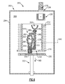
Figure 6 is a schematic view of an example casting apparatus for producing variable density blades, according to an embodiment. - The embodiments, examples and alternatives of the preceding paragraphs, the claims, or the following description and drawings, including any of their various aspects or respective individual features, may be taken independently or in any combination. Features described in connection with one embodiment are applicable to all embodiments, unless such features are incompatible.
-
Figure 1 schematically illustrates agas turbine engine 20. Thegas turbine engine 20 is disclosed herein as a two-spool turbofan that generally incorporates afan section 22, acompressor section 24, acombustor section 26 and aturbine section 28. Alternative engines might include an augmenter section (not shown) among other systems or features. Thefan section 22 drives air along a bypass flow path B in a bypass duct defined within anacelle 15, while thecompressor section 24 drives air along a core flow path C for compression and communication into thecombustor section 26 then expansion through theturbine section 28. Although depicted as a two-spool turbofan gas turbine engine in the disclosed non-limiting embodiment, it should be understood that the concepts described herein are not limited to use with two-spool turbofans as the teachings may be applied to other types of turbine engines including three-spool architectures. - The
exemplary engine 20 generally includes alow speed spool 30 and ahigh speed spool 32 mounted for rotation about an engine central longitudinal axis A relative to an enginestatic structure 36 viaseveral bearing systems 38. It should be understood thatvarious bearing systems 38 at various locations may alternatively or additionally be provided, and the location ofbearing systems 38 may be varied as appropriate to the application. - The
low speed spool 30 generally includes aninner shaft 40 that interconnects afan 42, a first (or low)pressure compressor 44 and a first (or low)pressure turbine 46. Theinner shaft 40 is connected to thefan 42 through a speed change mechanism, which in exemplarygas turbine engine 20 is illustrated as a gearedarchitecture 48 to drive thefan 42 at a lower speed than thelow speed spool 30. Thehigh speed spool 32 includes anouter shaft 50 that interconnects a second (or high)pressure compressor 52 and a second (or high)pressure turbine 54. Acombustor 56 is arranged inexemplary gas turbine 20 between thehigh pressure compressor 52 and thehigh pressure turbine 54. Amid-turbine frame 57 of the enginestatic structure 36 is arranged generally between thehigh pressure turbine 54 and thelow pressure turbine 46. Themid-turbine frame 57 further supports bearingsystems 38 in theturbine section 28. Theinner shaft 40 and theouter shaft 50 are concentric and rotate via bearingsystems 38 about the engine central longitudinal axis A which is collinear with their longitudinal axes. Although geared architecture is described here, the disclosed airfoil is applicable to any engine with our without a geared architecture. - The core airflow is compressed by the
low pressure compressor 44 then thehigh pressure compressor 52, mixed and burned with fuel in thecombustor 56, then expanded over thehigh pressure turbine 54 andlow pressure turbine 46. Themid-turbine frame 57 includesairfoils 59 which are in the core airflow path C. Theturbines low speed spool 30 andhigh speed spool 32 in response to the expansion. It will be appreciated that each of the positions of thefan section 22,compressor section 24,combustor section 26,turbine section 28, and fandrive gear system 48 may be varied. For example,gear system 48 may be located aft ofcombustor section 26 or even aft ofturbine section 28, andfan section 22 may be positioned forward or aft of the location ofgear system 48. - The
engine 20 in one example is a high-bypass geared aircraft engine. In a further example, theengine 20 bypass ratio is greater than about six (6), with an example embodiment being greater than about ten (10), the gearedarchitecture 48 is an epicyclic gear train, such as a planetary gear system or other gear system, with a gear reduction ratio of greater than about 2.3 and thelow pressure turbine 46 has a pressure ratio that is greater than about five. In one disclosed embodiment, theengine 20 bypass ratio is greater than about ten (10:1), the fan diameter is significantly larger than that of thelow pressure compressor 44, and thelow pressure turbine 46 has a pressure ratio that is greater than about five 5:1.Low pressure turbine 46 pressure ratio is pressure measured prior to inlet oflow pressure turbine 46 as related to the pressure at the outlet of thelow pressure turbine 46 prior to an exhaust nozzle. The gearedarchitecture 48 may be an epicycle gear train, such as a planetary gear system or other gear system, with a gear reduction ratio of greater than about 2.3:1. It should be understood, however, that the above parameters are only exemplary of one embodiment of a geared architecture engine and that the present invention is applicable to other gas turbine engines including direct drive turbofans. - A significant amount of thrust is provided by the bypass flow B due to the high bypass ratio. The
fan section 22 of theengine 20 is designed for a particular flight condition -- typically cruise at about 0.8 Mach and about 35,000 feet (10,668 meters). The flight condition of 0.8 Mach and 35,000 ft (10,668 meters), with the engine at its best fuel consumption - also known as "bucket cruise Thrust Specific Fuel Consumption ('TSFC')" - is the industry standard parameter of lbm of fuel being burned divided by lbf of thrust the engine produces at that minimum point. "Low fan pressure ratio" is the pressure ratio across the fan blade alone, without a Fan Exit Guide Vane ("FEGV") system. The low fan pressure ratio as disclosed herein according to one non-limiting embodiment is less than about 1.45. "Low corrected fan tip speed" is the actual fan tip speed in ft/sec divided by an industry standard temperature correction of [(Tram °R) / (518.7 °R)]0.5. The "Low corrected fan tip speed" as disclosed herein according to one non-limiting embodiment is less than about 1150 ft / second (350.5 meters/second). - Referring to
Figures 2A and 2B , aroot 74 of eachturbine blade 64 is mounted to the rotor disk. Theturbine blade 64 includes aplatform 76, which provides the inner flow path, supported by theroot 74. Anairfoil 78 extends in a radial direction R from theplatform 76 to atip 80. It should be understood that the turbine blades may be integrally formed with the rotor such that the roots are eliminated. In such a configuration, the platform is provided by the outer diameter of the rotor. Theairfoil 78 provides leading and trailingedges tip 80 is arranged adjacent to a blade outer air seal (not shown). - The
airfoil 78 ofFigure 2B schematically illustrates exterior airfoil surface extending in a chord-wise direction C from a leadingedge 82 to a trailingedge 84. Theairfoil 78 is provided between pressure (typically concave) and suction (typically convex)wall Multiple turbine blades 64 are arranged circumferentially in direction A. Theairfoil 78 extends from theplatform 76 in the radial direction R, or spanwise, to thetip 80. - The
airfoil 78 includes acooling passage 90 provided between the pressure andsuction walls cooling passage 90. - The
turbine blade 64 may be fabricated of superalloy materials, such as cobalt- or nickel-based alloys. Referring toFigure 3 , theairfoil 78 has afirst portion 92 near an airfoil base fabricated of a first material. In the example, the airfoil base is theplatform 76, although the airfoil base may be a root of a platformless blade. Theairfoil 78 also includes asecond portion 94 near the tip 80 (proximate to a blade outer air seal 89) fabricated of a second, different material. For example, the first and second materials differ in at least one of composition, microstructure and mechanical properties. In a further example, the first and second materials differ in at least density. - In one example, the first material (near the base portion of the blade 64) has a relatively higher density and the second material (near the tip 80) has a relatively lower density. In this manner, the pull forces at the tip may be reduced, which enables more material to be used at the tip without requiring additional material near the base of the airfoil for structural integrity of the blade. The first and second materials can additionally differ in other characteristics, such as corrosion resistance, strength, creep resistance, fatigue resistance, or the like.
- Although first and second portions are discussed, the airfoil may include more than two portions. Moreover, the portions may not be discrete. Instead, the first and second portions are metallurgically bonded to each other in a boundary zone having a mixture of the first material and the second material. In this manner, the material composition transitions between the portions.
- Referring to
Figure 5 , an array 98 ofblade airfoils 78 are shown circumferentially spaced apart from one another agap 100. Eachairfoil 78 extends in the radial direction R from a 0% span position near the airfoil base to a 100% span position at thetip 80, as best shown inFigure 3 . - In one embodiment, the
first portion 92 may extend from the 0% span position to the 70% span position, and thesecond portion 94 may extend from the 70% span position to the 100% span position. In another embodiment, the second portion is in the range of 90% span to 100% span. - A
midspan region 96 may extend from the 20% span position to the 80% span position, overlapping the first andsecond portions airfoil 78 may have an hourglass-like shape such that the midspan region is necked. In particular, thesecond portion 94 has increasing axial and/ortrue chord lengths edge 82 to the trailingedge 84, in the axial and chord-wise direction x, c, respectively. In addition to increasing axial chord at the tip, the tip true chord is also increased by increasing the height 73 of the leading edge airfoil section, as shown inFigure. 2B . - The
airfoil 78 is illustrated inFigure 3 as flaring outwardly in the chordwise direction C at both the leading and trailingedges Figure 4 ) or the trailing edge position may be varied to increase the chord near thetip 80. - The leading and trailing
edges engine 20. Thus, if the leading edge flares outward in the chord-wise direction, the leading edge axial position is less positive as a span position in the radial direction increases along thesecond portion 94. If the trailing edge flares outward in the chord-wise direction, the trailing edge axial position is more positive as a span position in the radial direction increases along thesecond portion 94. - Any suitable process may be used to provide the disclosed variable density airfoil. One example manufacturing method is set forth in United States Patent Application Serial Number
14/106,007 - In one example, the
blade 64 is fabricated using a casting process. For example, the casting process can be an investment casting process that is used to cast a single crystal microstructure (with no high angle boundaries), a directional (columnar grain) microstructure, or an equiaxed microstructure. In one example of fabricating theblade 64 by casting, the casting process introduces two, or more, alloys that correspond to the first and second (or more) materials. For example, the alloys are poured into an investment casting mold at different stages in the cooling cycle to form the first andsecond portions blade 64. The following example is based on a directionally solidified, single crystal casting technique to fabricate a nickel-based blade, but can also be applied to other casting techniques, and other material compositions. - At least two nickel-based alloys of different composition (and different density upon cooling) are poured into an investment casting mold at different stages of the withdrawal and solidification process of the casting.
- A tip-upward or tip-downward casting technique may be used, for example. In a tip-downward casting, shown schematically in
Figure 6 , a low density alloy will be poured just sufficient to fill the outboard portion, and withdrawal process begins. As the transition location in the cavity approaches the baffle, a different alloy with higher creep strength is poured to fill the rest of the mold. This may be achieved by adding ingot(s) of the heavier alloy in the melt crucible and pouring the molten heavier alloy into the pour cup. - A
baseline casting system 200 comprises afurnace 202 which includes avacuum chamber 204 having an interior 206. For heating a mold orshell 210, the furnace includes aninduction coil 212 surrounding asusceptor 214. - A
baffle 216 is positioned at the bottom of the susceptor and has a central opening oraperture 218 for downwardly passing theshell 210 as it is withdrawn from a heating zone defined by the coil and susceptor and allowed to cool as it passes below the baffle. The shell is supported atop a chill plate 220 (e.g., water cooled) which is held by an elevator oractuator 222 to vertically move the chill plate (e.g., descend in a downward direction 580). - A
melt crucible 230 receives meltedmetallic ingots 232. The ingots may be introduced through anair lock 234 and deposited into the crucible for melting. The crucible may have an actuator (not shown) for pouring the alloy into a pourcup 250 of the shell. - The exemplary shell is for casting a blade in a tip downward condition and has an
internal cavity 252 generally corresponding to features of such blade. At a lower end of the shell, the shell includes astarter seed 254. A spiral starter passageway (helical grain starter) 256 extends upward to the cavity. - For introducing alloy to the
cavity 252, a downsprue orfeeder 260 extends downwardly from a base of the cup. Theexemplary downsprue 260 contains aninline filter 262. In an embodiment, a modification may be made that involves splitting the downsprue or feeder into two branches for respectively introducing two pours of two different alloys. The downsprue includes a first branch which may provide a bottom fill and may comprise aconduit 270 having anoutlet port 272 relatively low on the shell. Theexemplary port 272 is below the desiredtransition 540 and, more particularly, below the lowest end of the part to be cast. The exemplary outlet may be positioned to direct flow to the seed (if any) 254 andhelical grain starter 256 so that the flowpath passes downward through this branch and upward through the grain starter to a port at the mold cavity where the blade is molded (e.g., at the tip). In this embodiment, however, asecond branch 280 branches off the downsprue downstream of the filter. The second branch provides a top fill flowpath to aport 282 relatively high on the shell. Theexemplary port 282 is at a top of the mold cavity (e.g., at the inner diameter (ID) end of the root). As is discussed further below, withdrawal may be synchronized so that a first pour of one alloy may pass through the first branch (and optionally or preferably not the second branch) to provide a desired amount of a first alloy in a tip inward region. Thereafter, a second pour of a second alloy may be applied to the same pour cup. However, the second pour will find the first branch blocked because, along at least a portion of the first flowpath, by the metal 290 of the first pour which will have solidified to block further communication. Accordingly, the second pour or shot will pass as a top fill through the second port. This top fill does not block further pours until the cavity is full. Accordingly, the second pour may terminate before the cavity is filled and a third pour (through the second port) may similarly fill a remainder of the cavity to create three zones of differing composition. In various embodiments, this process might be extended to allow additional pours. - It should also be understood that although a particular component arrangement is disclosed in the illustrated embodiment, other arrangements will benefit herefrom. Although particular step sequences are shown, described, and claimed, it should be understood that steps may be performed in any order, separated or combined unless otherwise indicated and will still benefit from the present invention.
- Although the different examples have specific components shown in the illustrations, embodiments of this invention are not limited to those particular combinations. It is possible to use some of the components or features from one of the examples in combination with features or components from another one of the examples.
- Although an example embodiment has been disclosed, a worker of ordinary skill in this art would recognize that certain modifications would come within the scope of the claims. For that reason, the following claims should be studied to determine their true scope and content.
Claims (12)
- A blade (64) for a gas turbine engine comprising:a body including an airfoil (78) extending in a radial direction from a 0% span position near an airfoil base to a 100% span position at an airfoil tip (80), the airfoil (78) including a first portion (92) near the airfoil base with a first density, and including a second portion (94) near the airfoil tip (80) with a second density, the second density is less than the first density, the second portion (94) including an increasing true chord length (72) in the radial direction.
- The blade according to claim 1, wherein the second portion (94) is in the range of 70% span to 100% span.
- The blade according to claim 1, wherein the second portion (94) is in the range of 90% span to 100% span.
- The blade according to claim 2 or 3, wherein the airfoil (78) has a leading and a trailing edge (82,84) defining the true chord length, the leading edge (82) providing a leading edge axial position, and the trailing edge (84) providing a trailing edge axial position.
- The blade according to claim 4, wherein the leading edge axial position is less positive as a span position in the radial direction increases along the second portion (94).
- The blade according to claim 4, wherein the trailing edge axial position is more positive as a span position in the radial direction increases along the second portion (84).
- The blade according to claim 4, wherein the leading edge axial position is less positive as a span position in the radial direction increases along the second portion (94), and the trailing edge axial position is more positive as a span position in the radial direction increases along the second portion (84).
- The blade according to any preceding claim, wherein the airfoil is necked at a midspan region.
- The blade according to any preceding claim, wherein the airfoil base includes a platform (76).
- The blade according to any preceding claim, wherein the first portion (92) includes a first material that provides the first density, and the second portion (94) includes a second material that provides the second density and that differs from the first material in composition, the first and second portions are metallurgically bonded to each other in a boundary zone (96) having a mixture of the first material and the second material.
- An array of blades for a gas turbine engine comprising:multiple blades circumferentially spaced from one another, each blade being a blade according to any preceding claim.
- The array according to claim 11, wherein the array includes turbine blades (64) each having a cooling passage (90).
Applications Claiming Priority (1)
| Application Number | Priority Date | Filing Date | Title |
|---|---|---|---|
| US201462028476P | 2014-07-24 | 2014-07-24 |
Publications (3)
| Publication Number | Publication Date |
|---|---|
| EP2977551A2 true EP2977551A2 (en) | 2016-01-27 |
| EP2977551A3 EP2977551A3 (en) | 2016-05-11 |
| EP2977551B1 EP2977551B1 (en) | 2019-10-23 |
Family
ID=53773255
Family Applications (1)
| Application Number | Title | Priority Date | Filing Date |
|---|---|---|---|
| EP15177509.5A Active EP2977551B1 (en) | 2014-07-24 | 2015-07-20 | Gas turbine engine blade with variable density and wide chord tip |
Country Status (3)
| Country | Link |
|---|---|
| US (2) | US10316671B2 (en) |
| EP (1) | EP2977551B1 (en) |
| SG (1) | SG10201505408WA (en) |
Families Citing this family (1)
| Publication number | Priority date | Publication date | Assignee | Title |
|---|---|---|---|---|
| FR3115079B1 (en) * | 2020-10-12 | 2022-10-14 | Safran Aircraft Engines | BLADE IN COMPOSITE MATERIAL INCLUDING LEADING EDGE SHIELD, TURBOMACHINE INCLUDING BLADE |
Family Cites Families (11)
| Publication number | Priority date | Publication date | Assignee | Title |
|---|---|---|---|---|
| US4431376A (en) | 1980-10-27 | 1984-02-14 | United Technologies Corporation | Airfoil shape for arrays of airfoils |
| US5931641A (en) | 1997-04-25 | 1999-08-03 | General Electric Company | Steam turbine blade having areas of different densities |
| JP2002213206A (en) * | 2001-01-12 | 2002-07-31 | Mitsubishi Heavy Ind Ltd | Blade structure of gas turbine |
| DE102004054752A1 (en) * | 2004-11-12 | 2006-05-18 | Rolls-Royce Deutschland Ltd & Co Kg | Blade of a flow machine with extended edge profile depth |
| DE112006002658B4 (en) | 2005-10-11 | 2021-01-07 | General Electric Technology Gmbh | Turbomachine Blade |
| US7762783B2 (en) * | 2007-01-11 | 2010-07-27 | General Electric Company | Turbine blade apparatus |
| US8734107B2 (en) * | 2011-05-31 | 2014-05-27 | General Electric Company | Ceramic-based tip cap for a turbine bucket |
| US10655473B2 (en) | 2012-12-13 | 2020-05-19 | United Technologies Corporation | Gas turbine engine turbine blade leading edge tip trench cooling |
| WO2014093826A2 (en) | 2012-12-14 | 2014-06-19 | United Technologies Corporation | Multi-shot casting |
| EP3513889B1 (en) | 2012-12-14 | 2021-04-14 | Raytheon Technologies Corporation | Alloy and hybrid turbine blade for improved engine performance or architecture |
| US20150315974A1 (en) | 2012-12-17 | 2015-11-05 | United Technologies Corporation | Two spool gas generator with improved pressure split |
-
2015
- 2015-07-09 SG SG10201505408WA patent/SG10201505408WA/en unknown
- 2015-07-17 US US14/802,512 patent/US10316671B2/en active Active
- 2015-07-20 EP EP15177509.5A patent/EP2977551B1/en active Active
-
2019
- 2019-04-29 US US16/397,265 patent/US10954799B2/en active Active
Also Published As
| Publication number | Publication date |
|---|---|
| US20200024962A1 (en) | 2020-01-23 |
| EP2977551A3 (en) | 2016-05-11 |
| US10954799B2 (en) | 2021-03-23 |
| SG10201505408WA (en) | 2016-02-26 |
| US10316671B2 (en) | 2019-06-11 |
| US20160024935A1 (en) | 2016-01-28 |
| EP2977551B1 (en) | 2019-10-23 |
Similar Documents
| Publication | Publication Date | Title |
|---|---|---|
| US10449605B2 (en) | Method and apparatus for manufacturing a multi-alloy cast structure | |
| US10035185B2 (en) | Hybrid turbine blade for improved engine performance or architecture | |
| US11268387B2 (en) | Splayed tip features for gas turbine engine airfoil | |
| US9802248B2 (en) | Castings and manufacture methods | |
| US9752442B2 (en) | Airfoil with variable profile responsive to thermal conditions | |
| EP2971567B1 (en) | Method of fabricating an article with sections having different microstructures | |
| US20170001241A1 (en) | Metal powder casting | |
| US10024181B2 (en) | Casting of thin wall hollow airfoil sections | |
| US10954799B2 (en) | Gas turbine engine blade with variable density and wide chord tip | |
| EP2969314B1 (en) | Cast component having corner radius to reduce recrystallization |
Legal Events
| Date | Code | Title | Description |
|---|---|---|---|
| PUAI | Public reference made under article 153(3) epc to a published international application that has entered the european phase |
Free format text: ORIGINAL CODE: 0009012 |
|
| AK | Designated contracting states |
Kind code of ref document: A2 Designated state(s): AL AT BE BG CH CY CZ DE DK EE ES FI FR GB GR HR HU IE IS IT LI LT LU LV MC MK MT NL NO PL PT RO RS SE SI SK SM TR |
|
| AX | Request for extension of the european patent |
Extension state: BA ME |
|
| PUAL | Search report despatched |
Free format text: ORIGINAL CODE: 0009013 |
|
| AK | Designated contracting states |
Kind code of ref document: A3 Designated state(s): AL AT BE BG CH CY CZ DE DK EE ES FI FR GB GR HR HU IE IS IT LI LT LU LV MC MK MT NL NO PL PT RO RS SE SI SK SM TR |
|
| AX | Request for extension of the european patent |
Extension state: BA ME |
|
| RIC1 | Information provided on ipc code assigned before grant |
Ipc: F01D 5/28 20060101ALI20160406BHEP Ipc: F01D 5/14 20060101AFI20160406BHEP |
|
| RAP1 | Party data changed (applicant data changed or rights of an application transferred) |
Owner name: UNITED TECHNOLOGIES CORPORATION |
|
| STAA | Information on the status of an ep patent application or granted ep patent |
Free format text: STATUS: REQUEST FOR EXAMINATION WAS MADE |
|
| 17P | Request for examination filed |
Effective date: 20161110 |
|
| RBV | Designated contracting states (corrected) |
Designated state(s): AL AT BE BG CH CY CZ DE DK EE ES FI FR GB GR HR HU IE IS IT LI LT LU LV MC MK MT NL NO PL PT RO RS SE SI SK SM TR |
|
| STAA | Information on the status of an ep patent application or granted ep patent |
Free format text: STATUS: EXAMINATION IS IN PROGRESS |
|
| 17Q | First examination report despatched |
Effective date: 20180919 |
|
| GRAP | Despatch of communication of intention to grant a patent |
Free format text: ORIGINAL CODE: EPIDOSNIGR1 |
|
| STAA | Information on the status of an ep patent application or granted ep patent |
Free format text: STATUS: GRANT OF PATENT IS INTENDED |
|
| INTG | Intention to grant announced |
Effective date: 20190509 |
|
| GRAS | Grant fee paid |
Free format text: ORIGINAL CODE: EPIDOSNIGR3 |
|
| GRAA | (expected) grant |
Free format text: ORIGINAL CODE: 0009210 |
|
| STAA | Information on the status of an ep patent application or granted ep patent |
Free format text: STATUS: THE PATENT HAS BEEN GRANTED |
|
| AK | Designated contracting states |
Kind code of ref document: B1 Designated state(s): AL AT BE BG CH CY CZ DE DK EE ES FI FR GB GR HR HU IE IS IT LI LT LU LV MC MK MT NL NO PL PT RO RS SE SI SK SM TR |
|
| REG | Reference to a national code |
Ref country code: GB Ref legal event code: FG4D |
|
| REG | Reference to a national code |
Ref country code: CH Ref legal event code: EP |
|
| REG | Reference to a national code |
Ref country code: IE Ref legal event code: FG4D |
|
| REG | Reference to a national code |
Ref country code: DE Ref legal event code: R096 Ref document number: 602015040163 Country of ref document: DE |
|
| REG | Reference to a national code |
Ref country code: AT Ref legal event code: REF Ref document number: 1193849 Country of ref document: AT Kind code of ref document: T Effective date: 20191115 |
|
| REG | Reference to a national code |
Ref country code: NL Ref legal event code: MP Effective date: 20191023 |
|
| REG | Reference to a national code |
Ref country code: LT Ref legal event code: MG4D |
|
| PG25 | Lapsed in a contracting state [announced via postgrant information from national office to epo] |
Ref country code: SE Free format text: LAPSE BECAUSE OF FAILURE TO SUBMIT A TRANSLATION OF THE DESCRIPTION OR TO PAY THE FEE WITHIN THE PRESCRIBED TIME-LIMIT Effective date: 20191023 Ref country code: NL Free format text: LAPSE BECAUSE OF FAILURE TO SUBMIT A TRANSLATION OF THE DESCRIPTION OR TO PAY THE FEE WITHIN THE PRESCRIBED TIME-LIMIT Effective date: 20191023 Ref country code: LV Free format text: LAPSE BECAUSE OF FAILURE TO SUBMIT A TRANSLATION OF THE DESCRIPTION OR TO PAY THE FEE WITHIN THE PRESCRIBED TIME-LIMIT Effective date: 20191023 Ref country code: BG Free format text: LAPSE BECAUSE OF FAILURE TO SUBMIT A TRANSLATION OF THE DESCRIPTION OR TO PAY THE FEE WITHIN THE PRESCRIBED TIME-LIMIT Effective date: 20200123 Ref country code: FI Free format text: LAPSE BECAUSE OF FAILURE TO SUBMIT A TRANSLATION OF THE DESCRIPTION OR TO PAY THE FEE WITHIN THE PRESCRIBED TIME-LIMIT Effective date: 20191023 Ref country code: PT Free format text: LAPSE BECAUSE OF FAILURE TO SUBMIT A TRANSLATION OF THE DESCRIPTION OR TO PAY THE FEE WITHIN THE PRESCRIBED TIME-LIMIT Effective date: 20200224 Ref country code: NO Free format text: LAPSE BECAUSE OF FAILURE TO SUBMIT A TRANSLATION OF THE DESCRIPTION OR TO PAY THE FEE WITHIN THE PRESCRIBED TIME-LIMIT Effective date: 20200123 Ref country code: GR Free format text: LAPSE BECAUSE OF FAILURE TO SUBMIT A TRANSLATION OF THE DESCRIPTION OR TO PAY THE FEE WITHIN THE PRESCRIBED TIME-LIMIT Effective date: 20200124 Ref country code: LT Free format text: LAPSE BECAUSE OF FAILURE TO SUBMIT A TRANSLATION OF THE DESCRIPTION OR TO PAY THE FEE WITHIN THE PRESCRIBED TIME-LIMIT Effective date: 20191023 Ref country code: ES Free format text: LAPSE BECAUSE OF FAILURE TO SUBMIT A TRANSLATION OF THE DESCRIPTION OR TO PAY THE FEE WITHIN THE PRESCRIBED TIME-LIMIT Effective date: 20191023 Ref country code: PL Free format text: LAPSE BECAUSE OF FAILURE TO SUBMIT A TRANSLATION OF THE DESCRIPTION OR TO PAY THE FEE WITHIN THE PRESCRIBED TIME-LIMIT Effective date: 20191023 |
|
| PG25 | Lapsed in a contracting state [announced via postgrant information from national office to epo] |
Ref country code: IS Free format text: LAPSE BECAUSE OF FAILURE TO SUBMIT A TRANSLATION OF THE DESCRIPTION OR TO PAY THE FEE WITHIN THE PRESCRIBED TIME-LIMIT Effective date: 20200224 Ref country code: RS Free format text: LAPSE BECAUSE OF FAILURE TO SUBMIT A TRANSLATION OF THE DESCRIPTION OR TO PAY THE FEE WITHIN THE PRESCRIBED TIME-LIMIT Effective date: 20191023 Ref country code: HR Free format text: LAPSE BECAUSE OF FAILURE TO SUBMIT A TRANSLATION OF THE DESCRIPTION OR TO PAY THE FEE WITHIN THE PRESCRIBED TIME-LIMIT Effective date: 20191023 |
|
| PG25 | Lapsed in a contracting state [announced via postgrant information from national office to epo] |
Ref country code: AL Free format text: LAPSE BECAUSE OF FAILURE TO SUBMIT A TRANSLATION OF THE DESCRIPTION OR TO PAY THE FEE WITHIN THE PRESCRIBED TIME-LIMIT Effective date: 20191023 |
|
| REG | Reference to a national code |
Ref country code: DE Ref legal event code: R097 Ref document number: 602015040163 Country of ref document: DE |
|
| PG2D | Information on lapse in contracting state deleted |
Ref country code: IS |
|
| PG25 | Lapsed in a contracting state [announced via postgrant information from national office to epo] |
Ref country code: CZ Free format text: LAPSE BECAUSE OF FAILURE TO SUBMIT A TRANSLATION OF THE DESCRIPTION OR TO PAY THE FEE WITHIN THE PRESCRIBED TIME-LIMIT Effective date: 20191023 Ref country code: RO Free format text: LAPSE BECAUSE OF FAILURE TO SUBMIT A TRANSLATION OF THE DESCRIPTION OR TO PAY THE FEE WITHIN THE PRESCRIBED TIME-LIMIT Effective date: 20191023 Ref country code: DK Free format text: LAPSE BECAUSE OF FAILURE TO SUBMIT A TRANSLATION OF THE DESCRIPTION OR TO PAY THE FEE WITHIN THE PRESCRIBED TIME-LIMIT Effective date: 20191023 Ref country code: EE Free format text: LAPSE BECAUSE OF FAILURE TO SUBMIT A TRANSLATION OF THE DESCRIPTION OR TO PAY THE FEE WITHIN THE PRESCRIBED TIME-LIMIT Effective date: 20191023 Ref country code: IS Free format text: LAPSE BECAUSE OF FAILURE TO SUBMIT A TRANSLATION OF THE DESCRIPTION OR TO PAY THE FEE WITHIN THE PRESCRIBED TIME-LIMIT Effective date: 20200223 |
|
| REG | Reference to a national code |
Ref country code: AT Ref legal event code: MK05 Ref document number: 1193849 Country of ref document: AT Kind code of ref document: T Effective date: 20191023 |
|
| PLBE | No opposition filed within time limit |
Free format text: ORIGINAL CODE: 0009261 |
|
| STAA | Information on the status of an ep patent application or granted ep patent |
Free format text: STATUS: NO OPPOSITION FILED WITHIN TIME LIMIT |
|
| PG25 | Lapsed in a contracting state [announced via postgrant information from national office to epo] |
Ref country code: IT Free format text: LAPSE BECAUSE OF FAILURE TO SUBMIT A TRANSLATION OF THE DESCRIPTION OR TO PAY THE FEE WITHIN THE PRESCRIBED TIME-LIMIT Effective date: 20191023 Ref country code: SK Free format text: LAPSE BECAUSE OF FAILURE TO SUBMIT A TRANSLATION OF THE DESCRIPTION OR TO PAY THE FEE WITHIN THE PRESCRIBED TIME-LIMIT Effective date: 20191023 Ref country code: SM Free format text: LAPSE BECAUSE OF FAILURE TO SUBMIT A TRANSLATION OF THE DESCRIPTION OR TO PAY THE FEE WITHIN THE PRESCRIBED TIME-LIMIT Effective date: 20191023 |
|
| 26N | No opposition filed |
Effective date: 20200724 |
|
| PG25 | Lapsed in a contracting state [announced via postgrant information from national office to epo] |
Ref country code: SI Free format text: LAPSE BECAUSE OF FAILURE TO SUBMIT A TRANSLATION OF THE DESCRIPTION OR TO PAY THE FEE WITHIN THE PRESCRIBED TIME-LIMIT Effective date: 20191023 Ref country code: AT Free format text: LAPSE BECAUSE OF FAILURE TO SUBMIT A TRANSLATION OF THE DESCRIPTION OR TO PAY THE FEE WITHIN THE PRESCRIBED TIME-LIMIT Effective date: 20191023 |
|
| PG25 | Lapsed in a contracting state [announced via postgrant information from national office to epo] |
Ref country code: MC Free format text: LAPSE BECAUSE OF FAILURE TO SUBMIT A TRANSLATION OF THE DESCRIPTION OR TO PAY THE FEE WITHIN THE PRESCRIBED TIME-LIMIT Effective date: 20191023 |
|
| REG | Reference to a national code |
Ref country code: CH Ref legal event code: PL |
|
| REG | Reference to a national code |
Ref country code: BE Ref legal event code: MM Effective date: 20200731 |
|
| PG25 | Lapsed in a contracting state [announced via postgrant information from national office to epo] |
Ref country code: CH Free format text: LAPSE BECAUSE OF NON-PAYMENT OF DUE FEES Effective date: 20200731 Ref country code: LU Free format text: LAPSE BECAUSE OF NON-PAYMENT OF DUE FEES Effective date: 20200720 Ref country code: LI Free format text: LAPSE BECAUSE OF NON-PAYMENT OF DUE FEES Effective date: 20200731 |
|
| PG25 | Lapsed in a contracting state [announced via postgrant information from national office to epo] |
Ref country code: BE Free format text: LAPSE BECAUSE OF NON-PAYMENT OF DUE FEES Effective date: 20200731 |
|
| PG25 | Lapsed in a contracting state [announced via postgrant information from national office to epo] |
Ref country code: IE Free format text: LAPSE BECAUSE OF NON-PAYMENT OF DUE FEES Effective date: 20200720 |
|
| PG25 | Lapsed in a contracting state [announced via postgrant information from national office to epo] |
Ref country code: TR Free format text: LAPSE BECAUSE OF FAILURE TO SUBMIT A TRANSLATION OF THE DESCRIPTION OR TO PAY THE FEE WITHIN THE PRESCRIBED TIME-LIMIT Effective date: 20191023 Ref country code: MT Free format text: LAPSE BECAUSE OF FAILURE TO SUBMIT A TRANSLATION OF THE DESCRIPTION OR TO PAY THE FEE WITHIN THE PRESCRIBED TIME-LIMIT Effective date: 20191023 Ref country code: CY Free format text: LAPSE BECAUSE OF FAILURE TO SUBMIT A TRANSLATION OF THE DESCRIPTION OR TO PAY THE FEE WITHIN THE PRESCRIBED TIME-LIMIT Effective date: 20191023 |
|
| PG25 | Lapsed in a contracting state [announced via postgrant information from national office to epo] |
Ref country code: MK Free format text: LAPSE BECAUSE OF FAILURE TO SUBMIT A TRANSLATION OF THE DESCRIPTION OR TO PAY THE FEE WITHIN THE PRESCRIBED TIME-LIMIT Effective date: 20191023 |
|
| REG | Reference to a national code |
Ref country code: DE Ref legal event code: R081 Ref document number: 602015040163 Country of ref document: DE Owner name: RAYTHEON TECHNOLOGIES CORPORATION (N.D.GES.D.S, US Free format text: FORMER OWNER: UNITED TECHNOLOGIES CORPORATION, FARMINGTON, CONN., US Ref country code: DE Ref legal event code: R081 Ref document number: 602015040163 Country of ref document: DE Owner name: RTX CORPORATION (N.D.GES.D. STAATES DELAWARE),, US Free format text: FORMER OWNER: UNITED TECHNOLOGIES CORPORATION, FARMINGTON, CONN., US |
|
| P01 | Opt-out of the competence of the unified patent court (upc) registered |
Effective date: 20230520 |
|
| PGFP | Annual fee paid to national office [announced via postgrant information from national office to epo] |
Ref country code: GB Payment date: 20250619 Year of fee payment: 11 |
|
| PGFP | Annual fee paid to national office [announced via postgrant information from national office to epo] |
Ref country code: FR Payment date: 20250620 Year of fee payment: 11 |
|
| PGFP | Annual fee paid to national office [announced via postgrant information from national office to epo] |
Ref country code: DE Payment date: 20250620 Year of fee payment: 11 |
|
| REG | Reference to a national code |
Ref country code: DE Ref legal event code: R081 Ref document number: 602015040163 Country of ref document: DE Owner name: RTX CORPORATION (N.D.GES.D. STAATES DELAWARE),, US Free format text: FORMER OWNER: RAYTHEON TECHNOLOGIES CORPORATION (N.D.GES.D.STAATES DELAWARE), ARLINGTON, VA, US |