EP2976995A1 - Diagnostic testing headband - Google Patents
Diagnostic testing headband Download PDFInfo
- Publication number
- EP2976995A1 EP2976995A1 EP15178056.6A EP15178056A EP2976995A1 EP 2976995 A1 EP2976995 A1 EP 2976995A1 EP 15178056 A EP15178056 A EP 15178056A EP 2976995 A1 EP2976995 A1 EP 2976995A1
- Authority
- EP
- European Patent Office
- Prior art keywords
- lead
- leads
- headband
- user
- diagnostic testing
- Prior art date
- Legal status (The legal status is an assumption and is not a legal conclusion. Google has not performed a legal analysis and makes no representation as to the accuracy of the status listed.)
- Withdrawn
Links
- 238000002405 diagnostic procedure Methods 0.000 title claims description 13
- 238000012360 testing method Methods 0.000 claims description 13
- 239000006260 foam Substances 0.000 claims description 3
- 230000008878 coupling Effects 0.000 claims 4
- 238000010168 coupling process Methods 0.000 claims 4
- 238000005859 coupling reaction Methods 0.000 claims 4
- 210000003128 head Anatomy 0.000 description 9
- 230000001681 protective effect Effects 0.000 description 4
- 239000000853 adhesive Substances 0.000 description 3
- 230000001070 adhesive effect Effects 0.000 description 3
- 210000005069 ears Anatomy 0.000 description 3
- 210000001061 forehead Anatomy 0.000 description 3
- 229910000004 White lead Inorganic materials 0.000 description 2
- 229920003023 plastic Polymers 0.000 description 2
- LFQSCWFLJHTTHZ-UHFFFAOYSA-N Ethanol Chemical compound CCO LFQSCWFLJHTTHZ-UHFFFAOYSA-N 0.000 description 1
- 244000181917 Rubus leucodermis Species 0.000 description 1
- 235000011036 Rubus leucodermis Nutrition 0.000 description 1
- 235000003942 Rubus occidentalis Nutrition 0.000 description 1
- QVGXLLKOCUKJST-UHFFFAOYSA-N atomic oxygen Chemical compound [O] QVGXLLKOCUKJST-UHFFFAOYSA-N 0.000 description 1
- 238000000034 method Methods 0.000 description 1
- 238000012986 modification Methods 0.000 description 1
- 230000004048 modification Effects 0.000 description 1
- 229910052760 oxygen Inorganic materials 0.000 description 1
- 239000001301 oxygen Substances 0.000 description 1
- 239000007787 solid Substances 0.000 description 1
- 125000000391 vinyl group Chemical group [H]C([*])=C([H])[H] 0.000 description 1
- 229920002554 vinyl polymer Polymers 0.000 description 1
Images

Classifications
-
- A—HUMAN NECESSITIES
- A61—MEDICAL OR VETERINARY SCIENCE; HYGIENE
- A61B—DIAGNOSIS; SURGERY; IDENTIFICATION
- A61B5/00—Measuring for diagnostic purposes; Identification of persons
- A61B5/68—Arrangements of detecting, measuring or recording means, e.g. sensors, in relation to patient
- A61B5/6801—Arrangements of detecting, measuring or recording means, e.g. sensors, in relation to patient specially adapted to be attached to or worn on the body surface
- A61B5/6802—Sensor mounted on worn items
- A61B5/6803—Head-worn items, e.g. helmets, masks, headphones or goggles
-
- A—HUMAN NECESSITIES
- A61—MEDICAL OR VETERINARY SCIENCE; HYGIENE
- A61B—DIAGNOSIS; SURGERY; IDENTIFICATION
- A61B5/00—Measuring for diagnostic purposes; Identification of persons
- A61B5/68—Arrangements of detecting, measuring or recording means, e.g. sensors, in relation to patient
- A61B5/6801—Arrangements of detecting, measuring or recording means, e.g. sensors, in relation to patient specially adapted to be attached to or worn on the body surface
- A61B5/683—Means for maintaining contact with the body
- A61B5/6832—Means for maintaining contact with the body using adhesives
- A61B5/6833—Adhesive patches
-
- A—HUMAN NECESSITIES
- A61—MEDICAL OR VETERINARY SCIENCE; HYGIENE
- A61B—DIAGNOSIS; SURGERY; IDENTIFICATION
- A61B5/00—Measuring for diagnostic purposes; Identification of persons
- A61B5/24—Detecting, measuring or recording bioelectric or biomagnetic signals of the body or parts thereof
- A61B5/25—Bioelectric electrodes therefor
- A61B5/279—Bioelectric electrodes therefor specially adapted for particular uses
- A61B5/291—Bioelectric electrodes therefor specially adapted for particular uses for electroencephalography [EEG]
-
- A—HUMAN NECESSITIES
- A61—MEDICAL OR VETERINARY SCIENCE; HYGIENE
- A61B—DIAGNOSIS; SURGERY; IDENTIFICATION
- A61B5/00—Measuring for diagnostic purposes; Identification of persons
- A61B5/48—Other medical applications
- A61B5/4806—Sleep evaluation
-
- A—HUMAN NECESSITIES
- A61—MEDICAL OR VETERINARY SCIENCE; HYGIENE
- A61B—DIAGNOSIS; SURGERY; IDENTIFICATION
- A61B5/00—Measuring for diagnostic purposes; Identification of persons
- A61B5/68—Arrangements of detecting, measuring or recording means, e.g. sensors, in relation to patient
- A61B5/6801—Arrangements of detecting, measuring or recording means, e.g. sensors, in relation to patient specially adapted to be attached to or worn on the body surface
- A61B5/6813—Specially adapted to be attached to a specific body part
- A61B5/6814—Head
-
- A—HUMAN NECESSITIES
- A61—MEDICAL OR VETERINARY SCIENCE; HYGIENE
- A61B—DIAGNOSIS; SURGERY; IDENTIFICATION
- A61B2562/00—Details of sensors; Constructional details of sensor housings or probes; Accessories for sensors
- A61B2562/16—Details of sensor housings or probes; Details of structural supports for sensors
- A61B2562/164—Details of sensor housings or probes; Details of structural supports for sensors the sensor is mounted in or on a conformable substrate or carrier
-
- A—HUMAN NECESSITIES
- A61—MEDICAL OR VETERINARY SCIENCE; HYGIENE
- A61B—DIAGNOSIS; SURGERY; IDENTIFICATION
- A61B2562/00—Details of sensors; Constructional details of sensor housings or probes; Accessories for sensors
- A61B2562/22—Arrangements of medical sensors with cables or leads; Connectors or couplings specifically adapted for medical sensors
- A61B2562/221—Arrangements of sensors with cables or leads, e.g. cable harnesses
-
- A—HUMAN NECESSITIES
- A61—MEDICAL OR VETERINARY SCIENCE; HYGIENE
- A61B—DIAGNOSIS; SURGERY; IDENTIFICATION
- A61B2562/00—Details of sensors; Constructional details of sensor housings or probes; Accessories for sensors
- A61B2562/22—Arrangements of medical sensors with cables or leads; Connectors or couplings specifically adapted for medical sensors
- A61B2562/225—Connectors or couplings
- A61B2562/226—Connectors or couplings comprising means for identifying the connector, e.g. to prevent incorrect connection to socket
-
- A—HUMAN NECESSITIES
- A61—MEDICAL OR VETERINARY SCIENCE; HYGIENE
- A61B—DIAGNOSIS; SURGERY; IDENTIFICATION
- A61B5/00—Measuring for diagnostic purposes; Identification of persons
- A61B5/01—Measuring temperature of body parts ; Diagnostic temperature sensing, e.g. for malignant or inflamed tissue
-
- A—HUMAN NECESSITIES
- A61—MEDICAL OR VETERINARY SCIENCE; HYGIENE
- A61B—DIAGNOSIS; SURGERY; IDENTIFICATION
- A61B5/00—Measuring for diagnostic purposes; Identification of persons
- A61B5/02—Detecting, measuring or recording pulse, heart rate, blood pressure or blood flow; Combined pulse/heart-rate/blood pressure determination; Evaluating a cardiovascular condition not otherwise provided for, e.g. using combinations of techniques provided for in this group with electrocardiography or electroauscultation; Heart catheters for measuring blood pressure
- A61B5/024—Detecting, measuring or recording pulse rate or heart rate
- A61B5/02416—Detecting, measuring or recording pulse rate or heart rate using photoplethysmograph signals, e.g. generated by infrared radiation
-
- A—HUMAN NECESSITIES
- A61—MEDICAL OR VETERINARY SCIENCE; HYGIENE
- A61B—DIAGNOSIS; SURGERY; IDENTIFICATION
- A61B5/00—Measuring for diagnostic purposes; Identification of persons
- A61B5/24—Detecting, measuring or recording bioelectric or biomagnetic signals of the body or parts thereof
- A61B5/25—Bioelectric electrodes therefor
- A61B5/279—Bioelectric electrodes therefor specially adapted for particular uses
- A61B5/28—Bioelectric electrodes therefor specially adapted for particular uses for electrocardiography [ECG]
- A61B5/282—Holders for multiple electrodes
Definitions
- the present disclosure relates to diagnostic testing and, more particularly, to a diagnostic testing headband.
- a wire harness having a plurality of leads is utilized to connect the patient with a testing apparatus.
- the harness leads are connected with lead tabs positioned upon the patient's body.
- the wire harness has a connector connected to the testing apparatus measuring different body functions.
- the wire harness is extremely cumbersome and limits movement of the user.
- the harness includes very long leads, or wires, and is awkward to manipulate when the patient must move from one position to the other. Accordingly, it is desirable to have a diagnostic testing tool that enables the user to self attach himself or herself to the testing apparatus. Additionally, it is desirable to have an apparatus where the leads are readily accessible to the user. Additionally, it is desirable to have color coded leads to enable the user to readily position the leads onto the proper lead tabs on the user's body.
- the present disclosure provides such a device.
- a diagnostic testing headband comprises an elongated body with two ends.
- a mechanism couples the ends of the body with one another to fit around the user's head.
- At least one first lead is coupled with the body.
- the at least one first lead couples with a lead pad contacting the user's head when the body is placed on the user's head.
- At least one second lead extends from the body to couple with a lead pad on the user.
- An electrical harness is coupled with the body.
- the electrical harness electrically couples with the at least one first and second leads.
- the electrical harness includes a connector to couple with a testing apparatus.
- a plurality of first and second leads is present. Foam is positioned inside of the body.
- a first and second leads are color coded.
- a hook and loop fastener is utilized to connect the ends of the body together.
- the headband 10 includes a body 12, a plurality of stationary leads 14, a plurality of extending leads 16 and a wire harness 18.
- the body 12 is an elongated flexible member.
- the body 12 generally includes a vinyl or the like covering 20 with a foam insert 22 sandwiched between the covering 20.
- the body 12 is flexible and is enabled to wrap around a user's head.
- the body 12 includes ends 24, 26.
- the ends 24, 26 include fasteners 28, 30. Shown are hook and loop fasteners with the hooks at end 28 and the loops at end 30. However, various types of fasteners, such as snaps, hooks and latches, buttons, adjustable straps or the like may be utilized as fasteners to secure the ends of the body 12 together to enable the headband to be wrapped about the user's head.
- the body 12 includes at least one stationary lead 14 secured to the body 12.
- the leads 14, three are shown, are coupled with the body 12.
- the leads 14 are electrically coupled with the wire harness 18.
- the leads 14 are color coded with the lead 32 having a center body color coded in yellow.
- the middle button 34 is color coded in orange and button 36 is color coded in red.
- the at least one extending leads 16 hang from the body 12.
- the leads 16 include a wire 38 and a lead cap 40.
- the wires 38 are coupled with the wire harness 18.
- the leads 16 can be coupled with a testing apparatus.
- the extending leads 16 are illustrated with seven color coded wires 38 and caps 40.
- Lead 42 has its wire 38 color coded violet with a lead cap 40 having a heart shape.
- Lead 44 has a blue wire as well as a blue cap 40.
- Lead 46 is brown with a brown cap.
- Lead 48 includes a green wire 38 as well as a green cap 40.
- Leads 42-48 are positioned on one half of the user's body 12.
- Lead 50 has a white wire 38 as well as cap 40.
- Lead 52 has a grey wire with a grey cap 40.
- lead 54 has a black wire with a black cap.
- cap 40 of lead 54 has a heart shape. Leads 50-54 are positioned on the other half of the user's body 12.
- the harness 18 includes a wire assembly 60 running through the body 12.
- the wire assembly 60 is coupled with the stationary leads 14 as well as with the extending leads 16.
- the wire assembly 60 electrically couples the leads 14, 16 with the external wiring assembly tail 62.
- the tail 62 extends from the body 12.
- the tail 62 includes a plurality of connectors 64-68.
- the connector 64 is coupled with a test apparatus.
- the connector 66 is connected with an oxygen sensor that may be secured onto the user's finger.
- the connectors 68 are connected with a nasal thermistor cannula.
- the headband 10 enables the leads to be connected to a user's body, head and, in turn, to the testing apparatus.
- the headband 10 provides an aesthetic pleasing appearance as well as a non-cumbersome wiring harness.
- the present tail 62 connector can be removed from the testing apparatus while the leads remain on the user's body (head) so that the user can move easily from one position to a different position.
- a method of using the diagnostic headband 10 is as follows.
- the headband is grasped by the user and positioned so that the stationary leads 14 are directed towards the user.
- Three lead pads 70 are buttoned into the yellow 32, orange 34, and red 36 leads.
- the protective backing is kept in place on the pads 70 so that the adhesive surface of the lead pads 70 remains covered. Once buttoned, the three lead pads 70 are in place on the headband 10.
- Alcohol prep pad(s) are used to clean the face and behind the ears.
- the adhesive lead pads 70 are applied to the user's face and chest. In order to apply the lead pads 70, the protective backing is removed from the lead pad to reveal the adhesive surface. A lead pad 70 is applied to the left side of the user's face, slightly below the left eye.
- a lead pad is applied to the right side of the face, slightly above the right eye.
- a lead pad is applied to the left side of the chin, on the jawbone.
- a lead pad is applied to the right side of the chin, on the jawbone.
- the next lead pad is applied behind the left ear.
- the last two lead pads are attached to the user's chest, on the left and right sides, along the collarbone.
- the headband is strapped across the user's head.
- the middle lead pad contacts the center of the user's forehead.
- the headband 10 is tightly strapped on the user's head while pressing down the three lead pads in the headband to make sure they are well attached to the user's forehead.
- the Purple heart-shaped lead 42 is connected to the lead pad 70 on the left side of the chest. During lead attachment, the lead which the user is instructed to attached should blink back and forth. Blue lead pad alternates with solid color lead pad.
- the Black heart-shaped lead 54 is applied to the lead pad on the right side of the chest.
- the Blue lead 44 is applied to the lead pad behind the left ear.
- the Brown 46 is applied to the lead pad near the left eye.
- the Grey lead 52 is applied to the lead pad near the right eye.
- the Green lead 48 is applied to the lead pad on the left side of the chin.
- the White lead 50 is applied to the lead pad on the right side of the chin.
- a Nasal Thermistor is inserted into the nose so that the single thin wire rests in front of the mouth and route the wires behind the ears.
- the end of the Nasal Thermistor includes a white lead and a blue lead. Insert the leads into the matching connectors on the main black cable (Blue to blue; white to white).
- the Nasal Cannula is inserted into the nose.
- the hose is routed so that it goes behind the ears.
- a pulse-ox finger sensor is attached onto the index finger.
- the other end of the finger sensor cable is connected to the blue plastic clip attached to the main black cable.
- the headband cable and the nasal thermistor hose are connected to the testing apparatus.
- the end of the nasal cannula hose transparent plastic tube
- the main black cable with the large connector is attached to the testing apparatus by lining up the white dots on the cable tip and the large socket on the bottom of the testing apparatus.
Abstract
Description
- The present disclosure relates to diagnostic testing and, more particularly, to a diagnostic testing headband.
- When patients do diagnostic testing, such as sleep studies, a wire harness having a plurality of leads is utilized to connect the patient with a testing apparatus. The harness leads are connected with lead tabs positioned upon the patient's body. The wire harness has a connector connected to the testing apparatus measuring different body functions. The wire harness is extremely cumbersome and limits movement of the user. The harness includes very long leads, or wires, and is awkward to manipulate when the patient must move from one position to the other. Accordingly, it is desirable to have a diagnostic testing tool that enables the user to self attach himself or herself to the testing apparatus. Additionally, it is desirable to have an apparatus where the leads are readily accessible to the user. Additionally, it is desirable to have color coded leads to enable the user to readily position the leads onto the proper lead tabs on the user's body.
- Accordingly, the present disclosure provides such a device.
- Accordingly to the disclosure, a diagnostic testing headband comprises an elongated body with two ends. A mechanism couples the ends of the body with one another to fit around the user's head. At least one first lead is coupled with the body. The at least one first lead couples with a lead pad contacting the user's head when the body is placed on the user's head. At least one second lead extends from the body to couple with a lead pad on the user. An electrical harness is coupled with the body. The electrical harness electrically couples with the at least one first and second leads. The electrical harness includes a connector to couple with a testing apparatus. A plurality of first and second leads is present. Foam is positioned inside of the body. A first and second leads are color coded. Generally, a hook and loop fastener is utilized to connect the ends of the body together.
- Further areas of applicability will become apparent from the description provided herein. The description and specific examples in this summary are intended for purposes of illustration only and are not intended to limit the scope of the present disclosure.
- The drawings described herein are for illustrative purposes only of selected embodiments and not all possible implementations, and are not intended to limit the scope of the present disclosure.
-
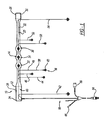
FIG. 1 is a plan view of a diagnostic headband. -
FIG. 2 is an enlarged plan view of the headband. -
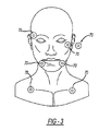
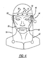
FIG. 3 is a schematic view of the user with the lead pads. -
FIG. 4 is a schematic view of the user with the leads attached to the lead pads. - Example embodiments will now be described more fully with reference to the accompanying drawings.
- Turning to the drawings, a diagnostic headband is illustrated and designated with the
reference numeral 10. Theheadband 10 includes abody 12, a plurality ofstationary leads 14, a plurality of extendingleads 16 and awire harness 18. - Turning to
FIG. 1 , thebody 12 is an elongated flexible member. Thebody 12 generally includes a vinyl or the like covering 20 with afoam insert 22 sandwiched between the covering 20. Thus, thebody 12 is flexible and is enabled to wrap around a user's head. - The
body 12 includesends ends fasteners end 28 and the loops atend 30. However, various types of fasteners, such as snaps, hooks and latches, buttons, adjustable straps or the like may be utilized as fasteners to secure the ends of thebody 12 together to enable the headband to be wrapped about the user's head. - The
body 12 includes at least onestationary lead 14 secured to thebody 12. Theleads 14, three are shown, are coupled with thebody 12. Theleads 14 are electrically coupled with thewire harness 18. Theleads 14 are color coded with thelead 32 having a center body color coded in yellow. Themiddle button 34 is color coded in orange andbutton 36 is color coded in red. These leads 32-36 connect with conventional lead tabs that are placed onto the user's forehead. - The at least one extending leads 16 hang from the
body 12. Theleads 16 include awire 38 and alead cap 40. Thewires 38 are coupled with thewire harness 18. Thus, in turn, theleads 16 can be coupled with a testing apparatus. The extendingleads 16 are illustrated with seven color codedwires 38 andcaps 40.Lead 42 has itswire 38 color coded violet with alead cap 40 having a heart shape.Lead 44 has a blue wire as well as ablue cap 40.Lead 46 is brown with a brown cap.Lead 48 includes agreen wire 38 as well as agreen cap 40. Leads 42-48 are positioned on one half of the user'sbody 12.Lead 50 has awhite wire 38 as well ascap 40.Lead 52 has a grey wire with agrey cap 40. Finally,lead 54 has a black wire with a black cap. Also,cap 40 oflead 54 has a heart shape. Leads 50-54 are positioned on the other half of the user'sbody 12. - The
harness 18 includes awire assembly 60 running through thebody 12. Thewire assembly 60 is coupled with the stationary leads 14 as well as with the extending leads 16. Thewire assembly 60 electrically couples theleads body 12. The tail 62 includes a plurality of connectors 64-68. Theconnector 64 is coupled with a test apparatus. The connector 66 is connected with an oxygen sensor that may be secured onto the user's finger. Theconnectors 68 are connected with a nasal thermistor cannula. - The
headband 10 enables the leads to be connected to a user's body, head and, in turn, to the testing apparatus. Theheadband 10 provides an aesthetic pleasing appearance as well as a non-cumbersome wiring harness. The present tail 62 connector can be removed from the testing apparatus while the leads remain on the user's body (head) so that the user can move easily from one position to a different position. - A method of using the
diagnostic headband 10 is as follows. The headband is grasped by the user and positioned so that the stationary leads 14 are directed towards the user. Threelead pads 70 are buttoned into the yellow 32,orange 34, and red 36 leads. The protective backing is kept in place on thepads 70 so that the adhesive surface of thelead pads 70 remains covered. Once buttoned, the threelead pads 70 are in place on theheadband 10. - Alcohol prep pad(s) are used to clean the face and behind the ears.
- The
adhesive lead pads 70 are applied to the user's face and chest. In order to apply thelead pads 70, the protective backing is removed from the lead pad to reveal the adhesive surface. Alead pad 70 is applied to the left side of the user's face, slightly below the left eye. - A lead pad is applied to the right side of the face, slightly above the right eye. A lead pad is applied to the left side of the chin, on the jawbone. A lead pad is applied to the right side of the chin, on the jawbone. The next lead pad is applied behind the left ear. The last two lead pads are attached to the user's chest, on the left and right sides, along the collarbone.
- Remove the protective backing from the three lead pads buttoned into the headband. Once the protective backing has been removed, the headband is strapped across the user's head. The middle lead pad contacts the center of the user's forehead. The
headband 10 is tightly strapped on the user's head while pressing down the three lead pads in the headband to make sure they are well attached to the user's forehead. - Connect the extending leads 16 to the
lead pads 70 applied to the face and chest. The leads are connected in a desired order. - The Purple heart-shaped
lead 42 is connected to thelead pad 70 on the left side of the chest. During lead attachment, the lead which the user is instructed to attached should blink back and forth. Blue lead pad alternates with solid color lead pad. - The Black heart-shaped
lead 54 is applied to the lead pad on the right side of the chest. TheBlue lead 44 is applied to the lead pad behind the left ear. TheBrown 46 is applied to the lead pad near the left eye. TheGrey lead 52 is applied to the lead pad near the right eye. TheGreen lead 48 is applied to the lead pad on the left side of the chin. TheWhite lead 50 is applied to the lead pad on the right side of the chin. - A Nasal Thermistor is inserted into the nose so that the single thin wire rests in front of the mouth and route the wires behind the ears. The end of the Nasal Thermistor includes a white lead and a blue lead. Insert the leads into the matching connectors on the main black cable (Blue to blue; white to white).
- Leaving all leads and the Nasal Thermistor attached, the Nasal Cannula is inserted into the nose. The hose is routed so that it goes behind the ears.
- A pulse-ox finger sensor is attached onto the index finger. The other end of the finger sensor cable is connected to the blue plastic clip attached to the main black cable.
- The headband cable and the nasal thermistor hose are connected to the testing apparatus. The end of the nasal cannula hose (transparent plastic tube) is threaded and twists onto the small lead on the bottom of the testing apparatus. The main black cable with the large connector is attached to the testing apparatus by lining up the white dots on the cable tip and the large socket on the bottom of the testing apparatus.
- The foregoing description of the embodiments has been provided for purposes of illustration and description. It is not intended to be exhaustive or to limit the disclosure. Individual elements or features of a particular embodiment are generally not limited to that particular embodiment, but, where applicable, are interchangeable and can be used in a selected embodiment, even if not specifically shown or described. The same may also be varied in many ways. Such variations are not to be regarded as a departure from the disclosure, and all such modifications are intended to be included within the scope of the disclosure.
Claims (7)
- A diagnostic testing headband comprising:an elongated body with two ends, a mechanism coupled with the body for connecting the two ends;at least one first lead coupled with the body for coupling with a lead pad contacting the user's body when the headband is placed on the user's head;at least one second lead extending from the body for coupling with a lead pad on the user; andan electrical harness coupled with the body, the electrical harness electrically coupled with the at least one first and second leads and the electrical harness including a connector for coupling with a testing apparatus.
- The diagnostic testing headband according to Claim 1, wherein a plurality of first leads is coupled with the body.
- The diagnostic testing headband of Claim 2, wherein the plurality of first leads is color coded.
- The diagnostic testing headband according to any one of the preceding Claims, wherein a plurality of second leads extend from the body.
- The diagnostic testing headband of Claim 4, wherein the plurality of second leads is color coded.
- The diagnostic testing headband according to any one of the preceding Claims, wherein foam is inside the body.
- The diagnostic testing headband according to any one of the preceding Claims, wherein the mechanism coupling for ends of the body is a hood and loop fastener.
Applications Claiming Priority (1)
| Application Number | Priority Date | Filing Date | Title |
|---|---|---|---|
| US14/339,073 US9788746B2 (en) | 2014-07-23 | 2014-07-23 | Diagnostic testing headband |
Publications (1)
| Publication Number | Publication Date |
|---|---|
| EP2976995A1 true EP2976995A1 (en) | 2016-01-27 |
Family
ID=53879313
Family Applications (1)
| Application Number | Title | Priority Date | Filing Date |
|---|---|---|---|
| EP15178056.6A Withdrawn EP2976995A1 (en) | 2014-07-23 | 2015-07-23 | Diagnostic testing headband |
Country Status (2)
| Country | Link |
|---|---|
| US (1) | US9788746B2 (en) |
| EP (1) | EP2976995A1 (en) |
Cited By (1)
| Publication number | Priority date | Publication date | Assignee | Title |
|---|---|---|---|---|
| CN107157471A (en) * | 2017-05-15 | 2017-09-15 | 德阳市人民医院 | A kind of precordial leads method for quickly identifying |
Citations (5)
| Publication number | Priority date | Publication date | Assignee | Title |
|---|---|---|---|---|
| US4638807A (en) * | 1985-08-27 | 1987-01-27 | Ryder International Corporation | Headband electrode system |
| US5363858A (en) * | 1993-02-11 | 1994-11-15 | Francis Luca Conte | Method and apparatus for multifaceted electroencephalographic response analysis (MERA) |
| US6510340B1 (en) * | 2000-01-10 | 2003-01-21 | Jordan Neuroscience, Inc. | Method and apparatus for electroencephalography |
| US20070208269A1 (en) * | 2004-05-18 | 2007-09-06 | Mumford John R | Mask assembly, system and method for determining the occurrence of respiratory events using frontal electrode array |
| US20100041962A1 (en) * | 2008-08-12 | 2010-02-18 | Elvir Causevic | Flexible headset for sensing brain electrical activity |
Family Cites Families (8)
| Publication number | Priority date | Publication date | Assignee | Title |
|---|---|---|---|---|
| US3735753A (en) * | 1971-11-09 | 1973-05-29 | Humetrics Corp | Head harness for eeg electrodes |
| US3896790A (en) * | 1972-05-01 | 1975-07-29 | Neuronics Inc | Alpha brain wave sensor |
| US4353372A (en) * | 1980-02-11 | 1982-10-12 | Bunker Ramo Corporation | Medical cable set and electrode therefor |
| US4595013A (en) * | 1984-08-17 | 1986-06-17 | Neurologics, Inc. | Electrode harness |
| US5622168A (en) * | 1992-11-18 | 1997-04-22 | John L. Essmyer | Conductive hydrogels and physiological electrodes and electrode assemblies therefrom |
| DE202008002129U1 (en) * | 2008-02-15 | 2008-07-03 | Ags-Medicare Gmbh | Arrangement for tapping potentials |
| WO2012050847A2 (en) * | 2010-09-28 | 2012-04-19 | Masimo Corporation | Depth of consciousness monitor including oximeter |
| FI126093B (en) * | 2012-11-12 | 2016-06-30 | Mega Elektroniikka Oy | Arrangement and method for conducting electrode measurements |
-
2014
- 2014-07-23 US US14/339,073 patent/US9788746B2/en not_active Expired - Fee Related
-
2015
- 2015-07-23 EP EP15178056.6A patent/EP2976995A1/en not_active Withdrawn
Patent Citations (5)
| Publication number | Priority date | Publication date | Assignee | Title |
|---|---|---|---|---|
| US4638807A (en) * | 1985-08-27 | 1987-01-27 | Ryder International Corporation | Headband electrode system |
| US5363858A (en) * | 1993-02-11 | 1994-11-15 | Francis Luca Conte | Method and apparatus for multifaceted electroencephalographic response analysis (MERA) |
| US6510340B1 (en) * | 2000-01-10 | 2003-01-21 | Jordan Neuroscience, Inc. | Method and apparatus for electroencephalography |
| US20070208269A1 (en) * | 2004-05-18 | 2007-09-06 | Mumford John R | Mask assembly, system and method for determining the occurrence of respiratory events using frontal electrode array |
| US20100041962A1 (en) * | 2008-08-12 | 2010-02-18 | Elvir Causevic | Flexible headset for sensing brain electrical activity |
Cited By (1)
| Publication number | Priority date | Publication date | Assignee | Title |
|---|---|---|---|---|
| CN107157471A (en) * | 2017-05-15 | 2017-09-15 | 德阳市人民医院 | A kind of precordial leads method for quickly identifying |
Also Published As
| Publication number | Publication date |
|---|---|
| US9788746B2 (en) | 2017-10-17 |
| US20160022211A1 (en) | 2016-01-28 |
Similar Documents
| Publication | Publication Date | Title |
|---|---|---|
| US10076279B2 (en) | System and method for a compact EEG headset | |
| JP6223971B2 (en) | Removable liner for sensor devices | |
| EP2866655B1 (en) | Photoplethysmography sensors | |
| US11622709B2 (en) | Headset and electrodes for sensing bioelectrical potential and methods of operation thereof | |
| EP2427107B1 (en) | Electrode fixing device | |
| US9345418B2 (en) | EEG net with transmission capabilities | |
| US11471107B2 (en) | Systems and methods for performing an electrocardiogram | |
| US5660168A (en) | Attachment arrangement | |
| US10945611B2 (en) | Ear thermometer | |
| US20150038810A1 (en) | Sensors for photoplethysmography at the ophthalmic artery region | |
| US9724002B2 (en) | Methods, devices and systems for photoplethysmography at the nasal columella | |
| US20150366503A1 (en) | Electrode fixing device | |
| EP2976995A1 (en) | Diagnostic testing headband | |
| WO2015083981A1 (en) | Hairwear having auxiliary device for head shaping or space formation | |
| US11311228B1 (en) | Multi-function apparatus, systems and methods for receiving signals from a human subject's head | |
| CN211633273U (en) | Wearable electroencephalogram detection device | |
| US20210030297A1 (en) | Portable electroencephalography devices | |
| KR20160146361A (en) | System for sensing and treatment of snoring and sleep apnea | |
| CN210931373U (en) | Patient transfer monitor with body temperature monitoring function | |
| WO2017198755A1 (en) | Headgear incorporating electrical measurement apparatus | |
| CN202681970U (en) | Stethoscope for pediatrics | |
| CN205268382U (en) | Eye -shade is used in nursing of neonate's internal medicine | |
| CN111683715A (en) | Wearable physiological data monitoring device and physiological data monitoring system | |
| CN211042505U (en) | Neonate's body temperature measuring device | |
| CN215305900U (en) | Blood oxygen monitoring earmuff and system |
Legal Events
| Date | Code | Title | Description |
|---|---|---|---|
| PUAI | Public reference made under article 153(3) epc to a published international application that has entered the european phase |
Free format text: ORIGINAL CODE: 0009012 |
|
| AK | Designated contracting states |
Kind code of ref document: A1 Designated state(s): AL AT BE BG CH CY CZ DE DK EE ES FI FR GB GR HR HU IE IS IT LI LT LU LV MC MK MT NL NO PL PT RO RS SE SI SK SM TR |
|
| AX | Request for extension of the european patent |
Extension state: BA ME |
|
| 17P | Request for examination filed |
Effective date: 20160727 |
|
| RBV | Designated contracting states (corrected) |
Designated state(s): AL AT BE BG CH CY CZ DE DK EE ES FI FR GB GR HR HU IE IS IT LI LT LU LV MC MK MT NL NO PL PT RO RS SE SI SK SM TR |
|
| STAA | Information on the status of an ep patent application or granted ep patent |
Free format text: STATUS: REQUEST FOR EXAMINATION WAS MADE |
|
| STAA | Information on the status of an ep patent application or granted ep patent |
Free format text: STATUS: THE APPLICATION IS DEEMED TO BE WITHDRAWN |
|
| 18D | Application deemed to be withdrawn |
Effective date: 20180201 |